EP3210709A2 - Ultrasound processing machine - Google Patents
Ultrasound processing machine Download PDFInfo
- Publication number
- EP3210709A2 EP3210709A2 EP17150862.5A EP17150862A EP3210709A2 EP 3210709 A2 EP3210709 A2 EP 3210709A2 EP 17150862 A EP17150862 A EP 17150862A EP 3210709 A2 EP3210709 A2 EP 3210709A2
- Authority
- EP
- European Patent Office
- Prior art keywords
- processing machine
- controller
- machine according
- workpiece
- tensile test
- Prior art date
- Legal status (The legal status is an assumption and is not a legal conclusion. Google has not performed a legal analysis and makes no representation as to the accuracy of the status listed.)
- Granted
Links
- 238000012545 processing Methods 0.000 title claims abstract description 61
- 238000002604 ultrasonography Methods 0.000 title description 2
- 238000009864 tensile test Methods 0.000 claims description 39
- 238000003466 welding Methods 0.000 claims description 14
- 238000003754 machining Methods 0.000 claims description 5
- 238000004891 communication Methods 0.000 claims description 2
- 239000003566 sealing material Substances 0.000 claims 1
- 238000012345 traction test Methods 0.000 claims 1
- 238000012360 testing method Methods 0.000 description 6
- 210000000056 organ Anatomy 0.000 description 3
- 229910000831 Steel Inorganic materials 0.000 description 2
- 238000006073 displacement reaction Methods 0.000 description 2
- 230000005489 elastic deformation Effects 0.000 description 2
- 230000010355 oscillation Effects 0.000 description 2
- 239000010959 steel Substances 0.000 description 2
- 230000006978 adaptation Effects 0.000 description 1
- 238000000418 atomic force spectrum Methods 0.000 description 1
- 238000005452 bending Methods 0.000 description 1
- 238000010276 construction Methods 0.000 description 1
- 238000013461 design Methods 0.000 description 1
- 230000000694 effects Effects 0.000 description 1
- 239000000463 material Substances 0.000 description 1
- 238000000275 quality assurance Methods 0.000 description 1
- 238000003908 quality control method Methods 0.000 description 1
- 238000012546 transfer Methods 0.000 description 1
Images

Classifications
-
- B—PERFORMING OPERATIONS; TRANSPORTING
- B29—WORKING OF PLASTICS; WORKING OF SUBSTANCES IN A PLASTIC STATE IN GENERAL
- B29C—SHAPING OR JOINING OF PLASTICS; SHAPING OF MATERIAL IN A PLASTIC STATE, NOT OTHERWISE PROVIDED FOR; AFTER-TREATMENT OF THE SHAPED PRODUCTS, e.g. REPAIRING
- B29C65/00—Joining or sealing of preformed parts, e.g. welding of plastics materials; Apparatus therefor
- B29C65/02—Joining or sealing of preformed parts, e.g. welding of plastics materials; Apparatus therefor by heating, with or without pressure
- B29C65/08—Joining or sealing of preformed parts, e.g. welding of plastics materials; Apparatus therefor by heating, with or without pressure using ultrasonic vibrations
-
- B—PERFORMING OPERATIONS; TRANSPORTING
- B23—MACHINE TOOLS; METAL-WORKING NOT OTHERWISE PROVIDED FOR
- B23K—SOLDERING OR UNSOLDERING; WELDING; CLADDING OR PLATING BY SOLDERING OR WELDING; CUTTING BY APPLYING HEAT LOCALLY, e.g. FLAME CUTTING; WORKING BY LASER BEAM
- B23K20/00—Non-electric welding by applying impact or other pressure, with or without the application of heat, e.g. cladding or plating
- B23K20/10—Non-electric welding by applying impact or other pressure, with or without the application of heat, e.g. cladding or plating making use of vibrations, e.g. ultrasonic welding
-
- B—PERFORMING OPERATIONS; TRANSPORTING
- B23—MACHINE TOOLS; METAL-WORKING NOT OTHERWISE PROVIDED FOR
- B23K—SOLDERING OR UNSOLDERING; WELDING; CLADDING OR PLATING BY SOLDERING OR WELDING; CUTTING BY APPLYING HEAT LOCALLY, e.g. FLAME CUTTING; WORKING BY LASER BEAM
- B23K37/00—Auxiliary devices or processes, not specially adapted to a procedure covered by only one of the preceding main groups
- B23K37/02—Carriages for supporting the welding or cutting element
- B23K37/0211—Carriages for supporting the welding or cutting element travelling on a guide member, e.g. rail, track
- B23K37/0229—Carriages for supporting the welding or cutting element travelling on a guide member, e.g. rail, track the guide member being situated alongside the workpiece
-
- B—PERFORMING OPERATIONS; TRANSPORTING
- B29—WORKING OF PLASTICS; WORKING OF SUBSTANCES IN A PLASTIC STATE IN GENERAL
- B29C—SHAPING OR JOINING OF PLASTICS; SHAPING OF MATERIAL IN A PLASTIC STATE, NOT OTHERWISE PROVIDED FOR; AFTER-TREATMENT OF THE SHAPED PRODUCTS, e.g. REPAIRING
- B29C65/00—Joining or sealing of preformed parts, e.g. welding of plastics materials; Apparatus therefor
- B29C65/74—Joining or sealing of preformed parts, e.g. welding of plastics materials; Apparatus therefor by welding and severing, or by joining and severing, the severing being performed in the area to be joined, next to the area to be joined, in the joint area or next to the joint area
- B29C65/743—Joining or sealing of preformed parts, e.g. welding of plastics materials; Apparatus therefor by welding and severing, or by joining and severing, the severing being performed in the area to be joined, next to the area to be joined, in the joint area or next to the joint area using the same tool for both joining and severing, said tool being monobloc or formed by several parts mounted together and forming a monobloc
- B29C65/7443—Joining or sealing of preformed parts, e.g. welding of plastics materials; Apparatus therefor by welding and severing, or by joining and severing, the severing being performed in the area to be joined, next to the area to be joined, in the joint area or next to the joint area using the same tool for both joining and severing, said tool being monobloc or formed by several parts mounted together and forming a monobloc by means of ultrasonic vibrations
-
- B—PERFORMING OPERATIONS; TRANSPORTING
- B29—WORKING OF PLASTICS; WORKING OF SUBSTANCES IN A PLASTIC STATE IN GENERAL
- B29C—SHAPING OR JOINING OF PLASTICS; SHAPING OF MATERIAL IN A PLASTIC STATE, NOT OTHERWISE PROVIDED FOR; AFTER-TREATMENT OF THE SHAPED PRODUCTS, e.g. REPAIRING
- B29C65/00—Joining or sealing of preformed parts, e.g. welding of plastics materials; Apparatus therefor
- B29C65/82—Testing the joint
- B29C65/8207—Testing the joint by mechanical methods
- B29C65/8215—Tensile tests
-
- B—PERFORMING OPERATIONS; TRANSPORTING
- B29—WORKING OF PLASTICS; WORKING OF SUBSTANCES IN A PLASTIC STATE IN GENERAL
- B29C—SHAPING OR JOINING OF PLASTICS; SHAPING OF MATERIAL IN A PLASTIC STATE, NOT OTHERWISE PROVIDED FOR; AFTER-TREATMENT OF THE SHAPED PRODUCTS, e.g. REPAIRING
- B29C66/00—General aspects of processes or apparatus for joining preformed parts
- B29C66/80—General aspects of machine operations or constructions and parts thereof
- B29C66/83—General aspects of machine operations or constructions and parts thereof characterised by the movement of the joining or pressing tools
- B29C66/832—Reciprocating joining or pressing tools
- B29C66/8322—Joining or pressing tools reciprocating along one axis
-
- B—PERFORMING OPERATIONS; TRANSPORTING
- B29—WORKING OF PLASTICS; WORKING OF SUBSTANCES IN A PLASTIC STATE IN GENERAL
- B29C—SHAPING OR JOINING OF PLASTICS; SHAPING OF MATERIAL IN A PLASTIC STATE, NOT OTHERWISE PROVIDED FOR; AFTER-TREATMENT OF THE SHAPED PRODUCTS, e.g. REPAIRING
- B29C66/00—General aspects of processes or apparatus for joining preformed parts
- B29C66/80—General aspects of machine operations or constructions and parts thereof
- B29C66/84—Specific machine types or machines suitable for specific applications
- B29C66/847—Drilling standard machine type
-
- B—PERFORMING OPERATIONS; TRANSPORTING
- B29—WORKING OF PLASTICS; WORKING OF SUBSTANCES IN A PLASTIC STATE IN GENERAL
- B29C—SHAPING OR JOINING OF PLASTICS; SHAPING OF MATERIAL IN A PLASTIC STATE, NOT OTHERWISE PROVIDED FOR; AFTER-TREATMENT OF THE SHAPED PRODUCTS, e.g. REPAIRING
- B29C66/00—General aspects of processes or apparatus for joining preformed parts
- B29C66/90—Measuring or controlling the joining process
- B29C66/92—Measuring or controlling the joining process by measuring or controlling the pressure, the force, the mechanical power or the displacement of the joining tools
- B29C66/922—Measuring or controlling the joining process by measuring or controlling the pressure, the force, the mechanical power or the displacement of the joining tools by measuring the pressure, the force, the mechanical power or the displacement of the joining tools
- B29C66/9221—Measuring or controlling the joining process by measuring or controlling the pressure, the force, the mechanical power or the displacement of the joining tools by measuring the pressure, the force, the mechanical power or the displacement of the joining tools by measuring the pressure, the force or the mechanical power
-
- B—PERFORMING OPERATIONS; TRANSPORTING
- B29—WORKING OF PLASTICS; WORKING OF SUBSTANCES IN A PLASTIC STATE IN GENERAL
- B29C—SHAPING OR JOINING OF PLASTICS; SHAPING OF MATERIAL IN A PLASTIC STATE, NOT OTHERWISE PROVIDED FOR; AFTER-TREATMENT OF THE SHAPED PRODUCTS, e.g. REPAIRING
- B29C66/00—General aspects of processes or apparatus for joining preformed parts
- B29C66/90—Measuring or controlling the joining process
- B29C66/92—Measuring or controlling the joining process by measuring or controlling the pressure, the force, the mechanical power or the displacement of the joining tools
- B29C66/922—Measuring or controlling the joining process by measuring or controlling the pressure, the force, the mechanical power or the displacement of the joining tools by measuring the pressure, the force, the mechanical power or the displacement of the joining tools
- B29C66/9231—Measuring or controlling the joining process by measuring or controlling the pressure, the force, the mechanical power or the displacement of the joining tools by measuring the pressure, the force, the mechanical power or the displacement of the joining tools by measuring the displacement of the joining tools
-
- B—PERFORMING OPERATIONS; TRANSPORTING
- B29—WORKING OF PLASTICS; WORKING OF SUBSTANCES IN A PLASTIC STATE IN GENERAL
- B29C—SHAPING OR JOINING OF PLASTICS; SHAPING OF MATERIAL IN A PLASTIC STATE, NOT OTHERWISE PROVIDED FOR; AFTER-TREATMENT OF THE SHAPED PRODUCTS, e.g. REPAIRING
- B29C66/00—General aspects of processes or apparatus for joining preformed parts
- B29C66/90—Measuring or controlling the joining process
- B29C66/93—Measuring or controlling the joining process by measuring or controlling the speed
- B29C66/934—Measuring or controlling the joining process by measuring or controlling the speed by controlling or regulating the speed
-
- B—PERFORMING OPERATIONS; TRANSPORTING
- B29—WORKING OF PLASTICS; WORKING OF SUBSTANCES IN A PLASTIC STATE IN GENERAL
- B29C—SHAPING OR JOINING OF PLASTICS; SHAPING OF MATERIAL IN A PLASTIC STATE, NOT OTHERWISE PROVIDED FOR; AFTER-TREATMENT OF THE SHAPED PRODUCTS, e.g. REPAIRING
- B29C66/00—General aspects of processes or apparatus for joining preformed parts
- B29C66/90—Measuring or controlling the joining process
- B29C66/95—Measuring or controlling the joining process by measuring or controlling specific variables not covered by groups B29C66/91 - B29C66/94
- B29C66/951—Measuring or controlling the joining process by measuring or controlling specific variables not covered by groups B29C66/91 - B29C66/94 by measuring or controlling the vibration frequency and/or the vibration amplitude of vibrating joining tools, e.g. of ultrasonic welding tools
-
- G—PHYSICS
- G01—MEASURING; TESTING
- G01N—INVESTIGATING OR ANALYSING MATERIALS BY DETERMINING THEIR CHEMICAL OR PHYSICAL PROPERTIES
- G01N3/00—Investigating strength properties of solid materials by application of mechanical stress
- G01N3/08—Investigating strength properties of solid materials by application of mechanical stress by applying steady tensile or compressive forces
- G01N3/16—Investigating strength properties of solid materials by application of mechanical stress by applying steady tensile or compressive forces applied through gearing
-
- B—PERFORMING OPERATIONS; TRANSPORTING
- B23—MACHINE TOOLS; METAL-WORKING NOT OTHERWISE PROVIDED FOR
- B23K—SOLDERING OR UNSOLDERING; WELDING; CLADDING OR PLATING BY SOLDERING OR WELDING; CUTTING BY APPLYING HEAT LOCALLY, e.g. FLAME CUTTING; WORKING BY LASER BEAM
- B23K2103/00—Materials to be soldered, welded or cut
- B23K2103/30—Organic material
- B23K2103/42—Plastics
-
- G—PHYSICS
- G01—MEASURING; TESTING
- G01N—INVESTIGATING OR ANALYSING MATERIALS BY DETERMINING THEIR CHEMICAL OR PHYSICAL PROPERTIES
- G01N2203/00—Investigating strength properties of solid materials by application of mechanical stress
- G01N2203/0001—Type of application of the stress
- G01N2203/0003—Steady
-
- G—PHYSICS
- G01—MEASURING; TESTING
- G01N—INVESTIGATING OR ANALYSING MATERIALS BY DETERMINING THEIR CHEMICAL OR PHYSICAL PROPERTIES
- G01N2203/00—Investigating strength properties of solid materials by application of mechanical stress
- G01N2203/0014—Type of force applied
- G01N2203/0016—Tensile or compressive
- G01N2203/0017—Tensile
-
- G—PHYSICS
- G01—MEASURING; TESTING
- G01N—INVESTIGATING OR ANALYSING MATERIALS BY DETERMINING THEIR CHEMICAL OR PHYSICAL PROPERTIES
- G01N2203/00—Investigating strength properties of solid materials by application of mechanical stress
- G01N2203/02—Details not specific for a particular testing method
- G01N2203/026—Specifications of the specimen
- G01N2203/0298—Manufacturing or preparing specimens
Landscapes
- Engineering & Computer Science (AREA)
- Mechanical Engineering (AREA)
- Physics & Mathematics (AREA)
- Optics & Photonics (AREA)
- Life Sciences & Earth Sciences (AREA)
- Chemical & Material Sciences (AREA)
- Analytical Chemistry (AREA)
- Biochemistry (AREA)
- General Health & Medical Sciences (AREA)
- General Physics & Mathematics (AREA)
- Immunology (AREA)
- Pathology (AREA)
- Health & Medical Sciences (AREA)
- Investigating Strength Of Materials By Application Of Mechanical Stress (AREA)
- Pressure Welding/Diffusion-Bonding (AREA)
- General Electrical Machinery Utilizing Piezoelectricity, Electrostriction Or Magnetostriction (AREA)
Abstract
Eine Ultraschall-Bearbeitungsmaschine umfasst einen Ständer, der an einer Grundplatte anbringbar ist. Des Weiteren verfügt die Maschine über einen Schwingungsgenerator, mittels dessen ein Arbeitsorgan antreibbar ist, wobei der Schwingungsgenerator von einem in Längsrichtung des Ständers verschieblich geführten Schlitten getragen wird. Der Schlitten wird seinerseits von einem an dem Ständer angebrachten Linearantrieb getragen. Der Schwingungsgenerator befindet sich in der Flucht des Stellwegs des Linearantriebs.An ultrasonic processing machine comprises a stand which can be attached to a base plate. Furthermore, the machine has a vibration generator, by means of which a working member is driven, wherein the vibration generator is supported by a slidably guided in the longitudinal direction of the stator slide. The carriage is in turn carried by a mounted on the stand linear drive. The vibration generator is in alignment with the travel of the linear drive.
Description
Die vorliegende Erfindung betrifft eine Ultraschall-Bearbeitungsmaschine nach dem Oberbegriff des Anspruchs 1, deren als Arbeitsorgan dienende Sonotrode mittels eines Linearantriebs in Längsrichtung des Ständers verfahrbar ist.The present invention relates to an ultrasonic processing machine according to the preamble of
Derartige Bearbeitungsmaschinen können eine Grundplatte zur Aufnahme eines mit der Werkzeugmaschine zu bearbeitenden Werkstücks und einen Ständer umfassen, entlang dessen das Arbeitsorgan verschieblich geführt ist. Hierzu ist ein entlang der Längsrichtung des Ständers verschieblich geführter Schlitten vorgesehen, der einen Schwingungsgenerator trägt, mit dem eine als Arbeitsorgan dienende Sonotrode zu hochfrequenten Schwingungen angeregt werden kann. Wird der Schlitten mittels des Linearantriebs in Längsrichtung verfahren, bis die Sonotrode mit dem zu schweißenden Werkstück in Anlage gelangt, kann mittels des Linearantriebs über die Sonotrode eine gewünschte Schweißkraft auf das Werkstück aufgebracht werden, die es je nach Anwendungsfall auf eine bestimmte Größe einzustellen gilt, wozu eine entsprechend ausgebildete Kraftregelung vorgesehen sein kann.Such processing machines may comprise a base plate for receiving a workpiece to be machined with the machine tool and a stand along which the working member is slidably guided. For this purpose, a slidably guided along the longitudinal direction of the stator carriage is provided, which carries a vibration generator with which a serving as a working organ sonotrode can be excited to high-frequency oscillations. If the carriage is moved in the longitudinal direction by means of the linear drive until the sonotrode comes into contact with the workpiece to be welded, a desired welding force can be applied to the workpiece by means of the linear drive via the sonotrode, which must be set to a specific size depending on the application, what can be provided for a suitably trained force control.
Für eine solche Kraftregelung ist die Bearbeitungsmaschine mit einer Steuerung versehen, die den Antrieb und den Schwingungsgenerator steuert, wobei mit Hilfe einer Kraftmesseinrichtung und einer Wegmesseinrichtung, welche mit der Steuerung in Verbindung stehen, der Antrieb des Schlittens und der Schwingungsgenerator so angesteuert werden können, dass das Arbeitsorgan mit einem gewünschten Kraftverlauf gegen das Werkstück angestellt und dabei betätigt wird. Weiterhin ist eine Ausgabeeinrichtung zur Ausgabe von Betriebsparametern vorgesehen, um beispielsweise die Dauer der Bearbeitung, die eingebrachte Energie, die aufgebrachte Schweißkraft etc. ausgeben oder darstellen zu können.For such a force control, the processing machine is provided with a controller which controls the drive and the vibration generator, wherein the drive of the carriage and the vibration generator can be controlled by means of a force measuring device and a displacement measuring device, which are in communication with the controller the working member is employed with a desired force curve against the workpiece and thereby actuated. Furthermore, an output device for outputting operating parameters is provided in order to For example, the duration of processing, the energy introduced, the applied welding force, etc. to spend or represent.
Mit einer Ultraschall-Bearbeitungsmaschine der vorstehend beschriebenen Art können beispielsweise Kunststoffbauteile miteinander verschweißt werden, wobei es zur Qualitätssicherung erforderlich ist, dass die verschweißten Bauteile zumindest stichprobenartig auf die Qualität der Schweißverbindung hin untersucht werden. Hierzu werden die Bauteile üblicherweise in eine Zugprüfvorrichtung eingespannt, in welcher die Haltekraft der Schweißverbindung mittels Zugprüfung überprüft wird.With an ultrasonic processing machine of the type described above, for example, plastic components can be welded together, it being necessary for quality assurance that the welded components are examined at least randomly on the quality of the welded joint out. For this purpose, the components are usually clamped in a tensile tester, in which the holding force of the welded joint is checked by means of tensile test.
Der Erfindung liegt die Aufgabe zugrunde, eine Ultraschall-Bearbeitungsmaschine nach dem Oberbegriff des Anspruchs 1 dahingehend weiterzubilden, dass auf einfachste Weise kostengünstig und zeitsparend eine Zugprüfung von miteinander verschweißten Bauteilen möglich ist.The invention has the object of developing an ultrasonic processing machine according to the preamble of
Die Lösung dieser Aufgabe erfolgt durch die Merkmale des Anspruchs 1 und insbesondere dadurch, dass eine an dem Schlitten vorgesehene Aufnahmeeinrichtung vorgesehen ist, in die eine erste Werkstückhalterung einsetzbar ist. Mit der ersten Werkstückhalterung, die in die Aufnahmeeinrichtung einsetzbar ist, kann das zuvor verschweißte Werkstück, das zwei Komponenten umfasst, an der ersten Komponente befestigt werden. Weiterhin ist eine an der Grundplatte oder an dem Ständer befestigbare zweite Werkstückhalterung vorgesehen, mit der die zweite Komponente des Werkstücks für die Zugprüfung gehalten werden kann. Auf diese Weise ist es möglich, nach dem Zusammenschweißen der beiden Komponenten des Werkstücks an jeder Komponente eine der beiden Werkstückhalterungen anzubringen, so dass eine Komponente über die erste Werkstückhalterung mit dem Schlitten verbunden ist und die andere Komponente über die zweite Werkstückhalterung mit der Grundplatte oder dem Ständer so verbunden ist, dass durch Kraftbeaufschlagung eine Zugprüfung erfolgen kann. Erfindungsgemäß ist die Steuerung so ausgebildet und eingerichtet, dass manuell und/oder automatisch zwischen einem Bearbeitungszyklus und einem Zugprüfzyklus umgeschaltet werden kann.The solution of this object is achieved by the features of
Unter einem Bearbeitungszyklus wird ein Arbeitsablauf verstanden, bei dem Materialien miteinander verschweißt, getrennt und/oder versiegelt werden. Unter einem Zugprüfzyklus wird eine Betriebsweise der Bearbeitungsmaschine verstanden, bei der die Steuerung den Antrieb des Schlittens so ansteuert, dass ein verschweißtes Werkstück, dessen beide Komponenten mit den beiden Werkstückhalterungen verbunden sind, auf Zug beansprucht werden kann, wobei der bei der Zugbeanspruchung auftretende Kraft-Wegverlauf von der Kraftmesseinrichtung und der Wegmesseinrichtung aufgezeichnet wird. Auf diese Weise kann durch den Zugprüfzyklus eine Zugprüfung des Werkstücks erfolgen und es kann festgestellt und ausgegeben werden, ob die Zugprüfung den Anforderungen genügt, d.h. ob die zuvor hergestellte Schweißverbindung zufriedenstellend ist.A processing cycle is understood to mean a workflow in which materials are welded, separated and / or sealed together. A tensile testing cycle is understood to mean an operating mode of the processing machine in which the control activates the drive of the carriage in such a way that a welded workpiece, whose two components are connected to the two workpiece holders, can be subjected to tension, wherein the force occurring during the tensile stress is subjected to tensile force. Course is recorded by the force measuring device and the path measuring device. In this way, by the Zugprüfzyklus a tensile test of the workpiece can be done and it can be determined and issued whether the tensile test meets the requirements, i. whether the welded joint previously made is satisfactory.
Vorteilhafte Ausführungsformen der Erfindung sind in der Beschreibung, der Zeichnung sowie den Unteransprüchen beschrieben.Advantageous embodiments of the invention are described in the description, the drawings and the subclaims.
Nach einer ersten vorteilhaften Ausführungsform kann die Werkstückhalterung in die Aufnahmeeinrichtung einsetzbar sein, ohne dass das Arbeitsorgan entfernt werden muss. Auf diese Weise kann die Bearbeitungsmaschine nach einem Bearbeitungszyklus auf einfachste Weise zur Zugprüfung vorbereitet werden, indem die erste Werkstückhalterung in die an dem Schlitten vorgesehene Aufnahmeeinrichtung eingesetzt wird. Anschließend muss die erste Werkstückhalterung lediglich mit einer Komponente des verschweißten Werkstücks verbunden werden und die andere Komponente muss mit der an der Grundplatte oder an dem Ständer befestigten zweiten Werkstückhalterung gekoppelt werden, um das Werkstück auf Zug zu beanspruchen.According to a first advantageous embodiment, the workpiece holder can be used in the receiving device without the working member must be removed. In this way, the processing machine can be prepared after a processing cycle in the easiest way for tensile test by the first workpiece holder is inserted into the provided on the carriage receiving device. Subsequently, the first workpiece holder must be connected to only one component of the welded workpiece and the other component must be coupled to the attached to the base plate or on the stand second workpiece holder to stress the workpiece on train.
Grundsätzlich ist es ausreichend, wenn die Ultraschall-Bearbeitungsmaschine mit ihrem Ständer relativ zu einer Grundplatte positioniert ist, die ortsfest ist, beispielsweise relativ zu einer bereits vorhandenen Arbeitsplatte oder Arbeitsfläche. Es kann jedoch auch vorteilhaft sein, wenn der Ständer zusammen mit einer Grundplatte vorgesehen und mit dieser verbunden ist, so dass die Bearbeitungsmaschine portabel ist.In principle, it is sufficient if the ultrasonic processing machine is positioned with its stand relative to a base plate which is stationary, for example relative to an existing work surface or work surface. However, it may also be advantageous if the stand is provided together with a base plate and connected thereto, so that the processing machine is portable.
Mit der erfindungsgemäßen Bearbeitungsmaschine kann nicht nur auf eine separate Zugprüfmaschine vollständig verzichtet werden. Vielmehr ist es auch möglich, durch geeignete Ausbildung der Steuerung eine vereinfachte Qualitätskontrolle zu erzielen. So kann nach einer weiteren vorteilhaften Ausführungsform die Steuerung so ausgebildet und eingerichtet sein, dass diese in festlegbaren Intervallen automatisch zwischen einem Bearbeitungszyklus und einem Zugprüfzyklus umschaltet. Auf diese Weise kann durch die Steuerung zwangsweise vorgesehen werden, dass in einem gewünschten Intervall nach einer Bearbeitung, d.h. einem Verschweißen von zwei Komponenten eines Werkstücks, eine Zugprüfung erfolgt.With the processing machine according to the invention can not be completely dispensed only on a separate tensile testing machine. Rather, it is also possible to achieve a simplified quality control by suitable design of the controller. Thus, according to a further advantageous embodiment, the controller may be designed and set up such that it automatically switches at a definable interval between a processing cycle and a tensile test cycle. In this way, it can be forcibly provided by the controller that, at a desired interval after processing, i. a welding of two components of a workpiece, a tensile test is carried out.
Die Länge eines Intervalls kann nach einer weiteren vorteilhaften Ausführungsform durch die Anzahl an hintereinander bearbeiteten Werkstücken festlegbar sein. So kann beispielsweise die Steuerung so ausgebildet und eingerichtet sein, dass grundsätzlich eine Zugprüfung nach beispielsweise 25 erfolgten Schweißungen erfolgt.The length of an interval can be fixed according to a further advantageous embodiment by the number of successively machined workpieces. Thus, for example, the controller may be designed and set up so that, in principle, a tensile test is carried out after, for example, 25 completed welds.
Nach einer weiteren vorteilhaften Ausführungsform kann die Länge eines Intervalls von der Steuerung zufallsgesteuert festlegbar sein. So kann eine Zugprüfung nach einer zufälligen Anzahl von Bearbeitungszyklen bzw. Schweißvorgängen oder aber nach einer zufällig ausgewählten Zeitdauer vorgesehen werden. Auch ist es möglich, dass die Steuerung so ausgebildet und eingerichtet ist, dass beispielsweise pro Schicht zehn zufällig ausgewählte Teile einer Zugprüfung unterworfen werden müssen, indem die Bearbeitungsmaschine nach dem Verschweißen dieser Teile auf einen Zugprüfzyklus umschaltet. Die Bearbeitung weiterer Teile ist dann nur möglich, wenn die Zugprüfung des zuvor verschweißten Teils durchgeführt worden ist.According to a further advantageous embodiment, the length of an interval may be determined randomly by the controller. Thus, a tensile test after a random number of processing cycles or welding operations or after a randomly selected period can be provided. It is also possible that the control is designed and set up so that, for example, ten randomly selected parts per layer must be subjected to a tensile test by the processing machine after welding the latter Parts switched to a Zugprüfzyklus. The processing of other parts is only possible if the tensile test of the previously welded part has been performed.
Nach einer weiteren vorteilhaften Ausführungsform kann die Steuerung der Bearbeitungsmaschine eine Eingabeeinrichtung aufweisen, mit der in Abhängigkeit von dem Ergebnis von zumindest einer Zugprüfung die weitere Betriebsweise der Bearbeitungsmaschine vorgebbar ist. Hierdurch kann die Reaktion der Bearbeitungsmaschine auf ein (negatives) Ergebnis einer Zugprüfung eingestellt bzw. ausgewählt werden. Beispielsweise kann die Bearbeitungsmaschine komplett gesperrt werden, wenn eine bestimmte Anzahl von negativen Zugprüfungen hintereinander durchgeführt wurde. Auch kann als weitere Betriebsweise der Bearbeitungsmaschine vorgegeben werden, dass diese zunächst im normalen Betrieb weiterarbeitet, bis der nächste Fehler auftritt. Auch ist es möglich, der Steuerung vorzugeben, dass das negative Ergebnis der Zugprüfung gelöscht bzw. ignoriert wird, wenn für einen bestimmten sich anschließenden Zeitraum, beispielsweise innerhalb von drei Stunden, kein weiterer Fehler bei einer Zugprüfung aufgetreten ist.According to a further advantageous embodiment, the control of the processing machine may comprise an input device with which the further mode of operation of the processing machine can be predetermined as a function of the result of at least one tensile test. As a result, the response of the processing machine to a (negative) result of a tensile test can be set or selected. For example, the processing machine may be completely disabled when a certain number of negative pull tests have been performed consecutively. It can also be specified as a further mode of operation of the processing machine that it initially continues to operate in normal operation until the next error occurs. It is also possible to specify to the controller that the negative result of the train test is deleted or ignored if, for a certain subsequent period, for example within three hours, no further error has occurred in a train test.
Nach einer weiteren vorteilhaften Ausführungsform kann die Steuerung so ausgebildet und eingerichtet sein, dass ein unzureichendes Ergebnis einer Zugprüfung ausgegeben wird, und dass in diesem Fall durch die Steuerung eine sich anschließende vorbestimmte Anzahl und Reihenfolge an Bearbeitungs- und Zugprüfzyklen vorgegeben wird, die ausgeführt werden müssen. Beispielsweise kann über die Steuerung eine Feststellung getroffen werden, wie bei Schlechtteilen weiter verfahren werden soll, die eine Zugprüfung nicht bestanden haben,. Beispielsweise kann vorgegeben werden, dass zunächst zwei weitere Teile verschweißt und geprüft werden, bis in einen normalen Betrieb zurückgekehrt wird.According to a further advantageous embodiment, the controller may be designed and arranged such that an insufficient result of a tensile test is output, and in that case, the control specifies a subsequent predetermined number and sequence of machining and tensile testing cycles which must be performed , For example, a determination can be made via the controller as to how to proceed with bad parts that have failed a tensile test. For example, it can be specified that initially two further parts are welded and tested until they return to normal operation.
Nach einer weiteren vorteilhaften Ausführungsform kann die Ausgabeeinrichtung der Bearbeitungsmaschine mit einem mobilen Bediengerät, insbesondere drahtlos, koppelbar sein. Auf diese Weise ist es möglich, Informationen aus der Bearbeitung und auch aus der Zugprüfung an ein mobiles Bediengerät zu übertragen, beispielsweise an ein Smartphone mit Hilfe einer App. Anschließend kann dann über das Smartphone oder über ein sonstiges Bediengerät von einem Bediener entschieden werden, wie nach einem Schlechtteil weiter verfahren wird.According to a further advantageous embodiment, the output device of the processing machine with a mobile control device, in particular wireless, be coupled. In this way, it is possible to transfer information from the processing and also from the train test to a mobile operating device, for example to a smartphone using an app. Subsequently, it can then be decided by the operator via the smartphone or via another operating device, how to proceed after a bad part.
Nach einer weiteren vorteilhaften Ausführungsform kann die Bearbeitungsmaschine in Abhängigkeit von Ergebnissen der Zugprüfung durch die Steuerung sperrbar sein. Auf diese Weise kann sichergestellt werden, dass keine unnötigen Schlechtteile produziert werden, wenn das Ergebnis einer Zugprüfung wiederholt negativ ausgefallen sein sollte.According to a further advantageous embodiment, the processing machine can be blocked by the controller depending on the results of the tensile test. In this way it can be ensured that no unnecessary bad parts are produced if the result of a tensile test should have repeatedly been negative.
Mit der erfindungsgemäßen Bearbeitungsmaschine lassen sich nicht nur die hohen Kosten einer ansonsten erforderlichen Zugprüfungsmaschine einsparen. Vielmehr kann auch in kürzester Zeit und auf einfachste Weise von einem Bearbeitungszyklus auf einen Zugprüfungszyklus umgestellt werden. Die Zusatzkosten für eine Zugprüfung sind dabei minimal, da an sich sämtliche Hardwarekomponenten bereits in der Bearbeitungsmaschine selbst vorhanden sind. Zusätzlich vorgesehen werden müssen lediglich eine entsprechende Anpassung der Steuerung sowie die erste und die zweite Werkstückhalterung, die mit dem Schlitten bzw. der Grundplatte oder dem Ständer koppelbar sind.The processing machine according to the invention not only saves the high costs of an otherwise required tensile testing machine. Rather, it can be converted in a very short time and in the simplest way of a processing cycle to a Zugprüfungszyklus. The additional costs for a tensile test are minimal, since all hardware components are already present in the processing machine itself. In addition, only a corresponding adaptation of the control and the first and the second workpiece holder, which can be coupled to the carriage or the base plate or the stand, need to be provided.
Nachfolgend wird die Erfindung rein beispielhaft unter Bezugnahme auf die beigefügten Figuren erläutert. Es zeigen:
- Fig. 1
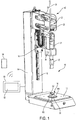
- eine perspektivische Darstellung einer erfindungsgemäßen Ultraschall-Bearbeitungsmaschine bei einem Bearbeitungszyklus;
- Fig.2
- eine perspektivische der Ultraschall-Bearbeitungsmaschine von
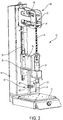
Fig. 1 bei einem Zugprüfzyklus; und - Fig. 3
- eine perspektivische Ansicht einer zweiten Ausführungsform einer Ultraschall-Bearbeitungsmaschine bei einem Zugprüfzyklus.
- Fig. 1
- a perspective view of an ultrasonic processing machine according to the invention in a processing cycle;
- Fig.2
- a perspective of the ultrasonic processing machine of
Fig. 1 at a tensile test cycle; and - Fig. 3
- a perspective view of a second embodiment of an ultrasonic processing machine in a Zugprüfzyklus.
Die in den
Um den Schlitten 18 samt Schwingungsgenerator 21 und Sonotrode 20 durch die Führungsschiene 16 geführt entlang des Ständers 14 verfahren zu können, ist bei dem beschriebenen Ausführungsbeispiel ein Linearantrieb 22 in Form eines Spindelantriebs vorgesehen, dessen Gewindespindel 24 derart an dem rahmenartigen Schlitten 14 aufrechtstehend angebracht ist, dass sich der Schwingungsgenerator 21 in der Flucht des Stellwegs des Linearantriebs 22, d.h. in der Spindelachse, befindet. Selbstverständlich sind auch andere Antriebe möglich. Der Linearantrieb 22 und insbesondere dessen Spindelmutter 28 wird bei der hier dargestellten Ausführungsform in der erfindungsgemäßen Art und Weise an einem in seiner Gesamtheit mit dem Bezugszeichen 40 bezeichneten rahmenartigen elastisch verformbaren Festkörpergelenk aus Stahl getragen, das seinerseits am freien Ende des Ständers 14 frei auskragend angebracht ist.In order to be able to move the
Zur Betätigung des Linearantriebs 22 ist ein Servomotor 26 vorgesehen, dessen Abtriebszahnrad über einen Riemen die Spindelmutter 28 antreibt, wozu diese entlang ihres Umfangs mit einer Außenverzahnung versehen ist.For actuating the
Zur Steuerung der Bearbeitungsmaschine für Bearbeitungszyklen und auch für Zugprüfzyklen ist eine Steuerung 50 vorgesehen, die eine Eingabeeinrichtung und eine Ausgabeeinrichtung zur Eingabe und zur Ausgabe von Betriebsparametern aufweist, beispielsweise in Form eines Touchscreens 52. Die Steuerung steht dabei sowohl mit dem Antrieb 22 wie auch mit der Kraftmesseinrichtung und der Wegmesseinrichtung sowie mit dem Schwingungsgenerator 21 in Verbindung. Durch passende Eingabe der erforderlichen Betriebsparameter kann mit Hilfe der Steuerung jeder gewünschte Bearbeitungsvorgang vorgegeben und durchgeführt werden. Während eines Zugprüfzyklus sorgt die Steuerung dafür, dass der Schlitten 18 mit einer vorgegebenen Kraftkennlinie nach oben bewegt wird, wobei der von dem Schlitten zurückgelegte Weg durch die Steuerung ermittelt und aufgezeichnet wird. Mit der Steuerung können somit die Zugprüfvorgänge protokolliert, gespeichert, dargestellt und in Datenform ausgegeben werden.For controlling the processing machine for processing cycles and also for tensile test cycles, a
Die Steuerung 50 ist weiterhin drahtlos mit einem mobilen Bediengerät 54, beispielsweise einem Smartphone, verbunden, mit dem über eine entsprechende App (Applikationssoftware) die Bearbeitungsmaschine ansteuerbar ist.The
In
Zum Verschweißen wird die Spindelmutter 28 mittels des Servomotors 26 angetrieben und hierdurch wird der Schlitten 18 einschließlich Schwingungsgenerator 21 und Sonotrode 20 abgesenkt bis die Sonotrode 20 mit der Komponente W1 des auf der Grundplatte 12 befindlichen Werkstücks in Anlage gelangt, wodurch mit Hilfe des Linearantriebs 22 über die Sonotrode 20 in der gewünschten Weise eine Schweißkraft auf das auf der Grundplatte 12 befindliche Werkstück aufgebracht werden kann, was insbesondere dann, wenn das Werkstück verhältnismäßig starr oder unnachgiebig ist, dazu führt, dass das rahmenartige Festkörpergelenk 40 in der gewünschten Weise eine elastische Verformung erfährt.For welding, the
Da sich erfindungsgemäß der Schwingungsgenerator 21 mitsamt seiner Sonotrode 20 in der Flucht des Stellwegs des Linearantriebs 22 befindet, treten außer dieser elastischen Verformung des elastisch verformbaren Festkörpergelenks 40 keine oder nur geringe Verformungen im Kraftflusspfad zwischen Sonotrode 20 und Ständer 14 auf. Da sich auch das Arbeitsorgan 20 in der Flucht des Stellwegs des Linearantriebs 22 befindet, wird sichergestellt, dass es infolge einer Kraft, die mit Hilfe des Linearantriebs 22 über das Arbeitsorgan 20 auf ein auf der Grundplatte 12 positionierbares Werkstück aufgebracht wird, zu keinen unkontrollierten Biegeverformungen im Bereich des Linearantriebs 22 und/oder des Schwingungsgenerators 21 kommt. Andererseits wird durch das Festkörpergelenk 40 bewusst zugelassen, dass der Linearantrieb 22 im Rahmen bestimmter Grenzen seine Hubbewegung ab dem Zeitpunkt, zu dem das Arbeitsorgan 20 mit dem Werkstück in Anlage gelangt, fortsetzen kann, um so aus der ab diesem Zeitpunkt auftretenden Hubbewegung die auf das Werkstück aufgebrachte Kraft einregeln zu können, ohne dass es zu Überschwingungen kommt.Since, according to the invention, the
Wenn nach einem Bearbeitungszyklus, bei dem die beiden Komponenten W1 und W2 des Werkstücks W miteinander verschweißt worden sind, ein Zugprüfzyklus durchlaufen werden soll oder muss, so kann die in
Die zweite Komponente W2 des Werkstücks W ist an der Grundplatte 12 mit Hilfe zweier rein schematisch dargestellter Werkstückhalterungen 34 und 36 so fixiert, dass die Werkstückkomponente W2 fest an der Grundplatte gehalten ist. Auf diese Weise kann bei Beaufschlagen der ersten Werkstückkomponente W1 mit einer Zugkraft die zuvor hergestellte Schweißverbindung getestet werden, indem der Verlauf der aufgebrachten Zugkraft über dem Weg aufgezeichnet wird.The second component W2 of the workpiece W is fixed to the
Wie aus
Bei Durchlaufen eines Zugprüfzyklus wird der Antrieb 22 durch die Steuerung 50 so angesteuert, dass dieser den Schlitten 18 mit einer vorgegebenen Zugkraft nach oben bewegt, wobei dabei mit Hilfe der Wegmesseinrichtung und der Kraftmesseinrichtung der Verlauf der Zugkraft über dem Weg ermittelt und aufgezeichnet wird. Sofern das Ergebnis voreingestellten Anforderungen genügt, wird über die Ausgabeeinrichtung 52 oder das Bediengerät 54 ein Signal abgegeben und/oder angezeigt bzw. gespeichert, das ein positives Durchlauft der Zugprüfung signalisiert. Sollte die Zugprüfung nicht den Anforderungen genügen, so wird dies ebenfalls ausgegeben bzw. signalisiert.When passing through a Zugprüfzyklus the
Die in
Bei der in
Die erste Werkstückhalterung 32 zur Zugprüfung, die wiederum nur rein schematisch dargestellt ist, ist bei dieser Ausführungsform in eine Aufnahmeeinrichtung 30 eingesetzt, die sich an der Unterseite des Schlittens 18 befindet. Eine mit der ersten Werkstückhalterung im Wesentlichen fluchtende zweite Werkstückhalterung 34 ist an der Grundplatte 12 befestigt, könnte jedoch auch an dem Ständer 14 befestigt sein. Zur Zugprüfung ist ein aus zwei Komponenten W1 und W2 zuvor zusammengeschweißtes Werkstück W zwischen den beiden Werkstückhalterungen 32 und 34 angeordnet, wobei die erste Werkstückhalterung 32 die Komponente W1 und die zweite Werkstückhalterung die Komponente W2 hält. Durch Betätigen des Antriebs 22 kann dann eine Kraft auf das Werkstück W in Pfeilrichtung ausgeübt werden, so dass die Festigkeit der Schweißverbindung zwischen den Komponenten W1 und W2 auf Zug geprüft werden kann.The
Bei den beiden Werkstückhalterungen 32 und 34 kann es sich in den einfachsten Fällen um Gewindestangen handeln, die mit ihren äußeren Enden in die Aufnahmeeinrichtung 30 bzw. die Grundplatte 12 eingeschraubt sind, wobei an den anderen Enden der beiden Gewindestangen Klemmeinrichtungen zum Halten der beiden Komponenten vorgesehen sein können.In the simplest cases, the two
Es versteht sich, dass auch bei der in
Im Übrigen ist die erfindungsgemäß vorgesehene Steuerung 50 so ausgebildet, wie dies in der Beschreibungseinleitung beschrieben wurde, so dass durch die Steuerung zwischen Bearbeitungszyklen und Zugprüfzyklen nach gewünschten Kriterien umgeschaltet werden kann.Incidentally, the
- 1010
- Ultraschall-BearbeitungsmaschineUltrasound machine
- 1212
- Grundplattebaseplate
- 1414
- Ständerstand
- 1616
- Führungsschieneguide rail
- 1818
- rahmenartiger Schlittenframe-like carriage
- 2020
- Arbeitsorgan/SonotrodeWorking body / horn
- 2121
- Schwingungsgeneratorvibration generator
- 2222
- Linearantrieblinear actuator
- 2424
- Spindelspindle
- 2626
- Servomotorservomotor
- 2828
- Spindelmutterspindle nut
- 3030
- Aufnahmeeinrichtungrecording device
- 3232
- erste Werkstückhalterungfirst workpiece holder
- 34, 3634, 36
- zweite Werkstückhalterungsecond workpiece holder
- 4040
- elastisch verformbares Festkörpergelenkelastically deformable solid-state joint
- 5050
- Steuerungcontrol
- 5252
- Eingabe- und AusgabeeinrichtungInput and output device
- 5454
- Bediengerätcontrol unit
- S1S1
- erste Schweißliniefirst welding line
- S2S2
- zweite Schweißliniesecond welding line
- WW
- Werkstückworkpiece
- W1W1
- erste Komponente des Werkstücksfirst component of the workpiece
- W2W2
- zweite Komponente des Werkstücksecond component of the workpiece
Claims (12)
dadurch gekennzeichnet, dass die erste Werkstückhalterung (32) in die Aufnahmeeinrichtung (30) einsetzbar ist, ohne das Arbeitsorgan (20) zu entfernen.Processing machine according to claim 1,
characterized in that the first workpiece holder (32) in the receiving device (30) can be used without removing the working member (20).
dadurch gekennzeichnet, dass der Ständer (14) mit der Grundplatte (12) verbunden ist.Processing machine according to claim 1 or 2,
characterized in that the stand (14) is connected to the base plate (12).
dadurch gekennzeichnet, dass die Steuerung (50) eine Geschwindigkeitsregelung für den Antrieb (22) aufweist.Processing machine according to claim 1, 2 and / or 3,
characterized in that the controller (50) has a speed control for the drive (22).
dadurch gekennzeichnet, dass die Steuerung (50) so ausgebildet und eingerichtet ist, dass diese in fest-legbaren Intervallen automatisch zwischen einem Bearbeitungszyklus und einem Zugprüfzyklus umschaltet.Processing machine according to at least one of the preceding claims,
characterized in that the controller (50) is constructed and arranged to automatically switch between a processing cycle and a traction test cycle at fixed intervals.
dadurch gekennzeichnet, dass die Länge eines Intervalls durch die Anzahl an hintereinander bearbeiteten Werkstücken (W) festlegbar ist.Processing machine according to claim 5,
characterized in that the length of an interval by the number of successively machined workpieces (W) can be fixed.
dadurch gekennzeichnet, dass die Länge eines Intervalls von der Steuerung (50) zufallsgesteuert festlegbar ist.Processing machine according to claim 5 and / or 6,
characterized in that the length of an interval from the controller (50) can be determined randomly.
dadurch gekennzeichnet, dass
die Steuerung (50) so ausgebildet und eingerichtet ist, dass diese während einer Bearbeitungsperiode für eine vorbestimmte Anzahl an Werkstücken (W) nach einem Bearbeitungszyklus in einen Zugprüfzyklus umschaltet.Processing machine according to at least one of the preceding claims,
characterized in that
the controller (50) is configured and arranged to switch to a tensile test cycle after a processing cycle for a predetermined number of workpieces (W) after a processing cycle.
dadurch gekennzeichnet, dass
die Steuerung (50) eine Eingabeeinrichtung aufweist, mit der in Abhängigkeit von dem Ergebnis von zumindest einer Zugprüfung die weitere Betriebsweise der Bearbeitungsmaschine vorgebbar ist.Processing machine according to at least one of the preceding claims,
characterized in that
the controller (50) has an input device with which the further operation of the processing machine can be predetermined as a function of the result of at least one tensile test.
dadurch gekennzeichnet, dass
die Steuerung (50) so ausgebildet und eingerichtet ist, dass ein unzureichendes Ergebnis einer Zugprüfung ausgebbar ist, und dass in diesem Fall durch die Steuerung eine sich anschließende vorbestimmte Anzahl und Reihenfolge an Bearbeitungs- und Zugprüfzyklen vorgegeben wird.Processing machine according to at least one of the preceding claims,
characterized in that
the controller (50) is designed and arranged such that an insufficient result of a tensile test can be output, and in that case the control sets a subsequent predetermined number and sequence of machining and tensile test cycles.
dadurch gekennzeichnet, dass
die Ausgabeeinrichtung (52) mit einem mobilen Bediengerät (54), insbesondere drahtlos koppelbar ist.Processing machine according to at least one of the preceding claims,
characterized in that
the output device (52) with a mobile control unit (54), in particular wirelessly coupled.
dadurch gekennzeichnet, dass
diese in Abhängigkeit von Ergebnissen der Zugprüfung durch die Steuerung (50) sperrbar ist.Processing machine according to at least one of the preceding claims,
characterized in that
this can be blocked in dependence on the results of the tensile test by the controller (50).
Priority Applications (2)
| Application Number | Priority Date | Filing Date | Title |
|---|---|---|---|
| PL17150862T PL3210709T3 (en) | 2016-02-08 | 2017-01-10 | Ultrasound processing machine |
| SI201730004T SI3210709T1 (en) | 2016-02-08 | 2017-01-10 | Ultrasound processing machine |
Applications Claiming Priority (1)
| Application Number | Priority Date | Filing Date | Title |
|---|---|---|---|
| DE102016102164.4A DE102016102164A1 (en) | 2016-02-08 | 2016-02-08 | Ultrasound machine |
Publications (3)
| Publication Number | Publication Date |
|---|---|
| EP3210709A2 true EP3210709A2 (en) | 2017-08-30 |
| EP3210709A3 EP3210709A3 (en) | 2017-12-27 |
| EP3210709B1 EP3210709B1 (en) | 2018-08-01 |
Family
ID=57758546
Family Applications (1)
| Application Number | Title | Priority Date | Filing Date |
|---|---|---|---|
| EP17150862.5A Active EP3210709B1 (en) | 2016-02-08 | 2017-01-10 | Ultrasound processing machine |
Country Status (8)
| Country | Link |
|---|---|
| US (1) | US9919471B2 (en) |
| EP (1) | EP3210709B1 (en) |
| DE (1) | DE102016102164A1 (en) |
| ES (1) | ES2693426T3 (en) |
| HU (1) | HUE041588T2 (en) |
| PL (1) | PL3210709T3 (en) |
| PT (1) | PT3210709T (en) |
| SI (1) | SI3210709T1 (en) |
Cited By (1)
| Publication number | Priority date | Publication date | Assignee | Title |
|---|---|---|---|---|
| CN108581172A (en) * | 2018-05-10 | 2018-09-28 | 刘超 | A kind of ultrasonic bonding holder structure |
Families Citing this family (5)
| Publication number | Priority date | Publication date | Assignee | Title |
|---|---|---|---|---|
| DE102013015685A1 (en) | 2013-09-23 | 2015-03-26 | Man Diesel & Turbo Se | machine tool |
| US10241090B2 (en) * | 2016-04-29 | 2019-03-26 | GM Global Technology Operations LLC | Method and apparatus for evaluating an ultrasonic weld junction |
| JP7077650B2 (en) * | 2018-02-16 | 2022-05-31 | トヨタ自動車株式会社 | Bonding device and bonding method |
| DE102018119618A1 (en) * | 2018-08-13 | 2020-02-13 | Branson Ultraschall Niederlassung Der Emerson Technologies Gmbh & Co. Ohg | Welding device and frame therefor |
| DE102021126774A1 (en) | 2021-10-15 | 2023-04-20 | Ms Ultraschall Technologie Gmbh | DEVICE AND METHOD FOR MACHINING A WORKPIECE |
Family Cites Families (19)
| Publication number | Priority date | Publication date | Assignee | Title |
|---|---|---|---|---|
| US4373653A (en) | 1981-09-10 | 1983-02-15 | Raytheon Company | Method and apparatus for ultrasonic bonding |
| DE4024778A1 (en) * | 1990-08-04 | 1992-02-06 | Nagel Masch Werkzeug | HON MEASURING TOOL |
| JPH04250334A (en) * | 1991-01-21 | 1992-09-07 | Sumitomo Metal Ind Ltd | Method and device for inspecting strip welded portion |
| GB2260096B (en) | 1991-08-31 | 1995-05-17 | Hydro Marine Systems Limited | A method of and apparatus for testing the integrity of a friction weld |
| DE4312439C2 (en) * | 1993-04-16 | 1995-02-09 | Ilch Hartmut Dipl Ing Fh | Device and method for welding a weld-on part and a base part |
| DE9313741U1 (en) | 1993-09-13 | 1995-01-19 | Still Gerhard | Device for testing a welded joint |
| US5788791A (en) | 1996-07-03 | 1998-08-04 | Branson Ultrasonics Corporation | Method of determining the collapse of plastic parts |
| US5894981A (en) | 1996-11-27 | 1999-04-20 | Orthodyne Electronics Corporation | Integrated pull tester with an ultrasonic wire bonder |
| JPH11281566A (en) * | 1998-03-26 | 1999-10-15 | Mekano Electronic Kk | Test method for semiconductor bump electrode |
| US6237833B1 (en) | 1998-06-15 | 2001-05-29 | Rohm Co., Ltd. | Method of checking wirebond condition |
| JP2001118887A (en) * | 1999-10-14 | 2001-04-27 | Resuka:Kk | Bonding strength testing device |
| JP3907951B2 (en) | 2001-01-18 | 2007-04-18 | 積水ハウス株式会社 | Welding equipment display device |
| EP1310319B1 (en) * | 2001-11-07 | 2006-09-06 | F & K Delvotec Bondtechnik GmbH | Wire bonder and testing method for wire bonds |
| US20090133803A1 (en) * | 2006-02-10 | 2009-05-28 | Sca Hygiene Products Ab | Device and Means of Processing a Material by Means of an Ultrasonic Device |
| US8052816B2 (en) * | 2006-05-08 | 2011-11-08 | Dukane Corporation | Ultrasonic press using servo motor with delayed motion |
| DE102006049624B4 (en) | 2006-10-20 | 2016-07-14 | Hesse Gmbh | ultrasonic Bonder |
| DE102010006130B4 (en) * | 2010-01-29 | 2014-11-06 | F&K Delvotec Semiconductor Gmbh | Method and arrangement for determining the quality of a wire bond connection |
| US8672211B2 (en) * | 2012-05-18 | 2014-03-18 | GM Global Technology Operations LLC | Vibration welding system with thin film sensor |
| DE102014101627A1 (en) * | 2014-02-10 | 2015-08-13 | Ms Spaichingen Gmbh | Rack for a machine |
-
2016
- 2016-02-08 DE DE102016102164.4A patent/DE102016102164A1/en not_active Withdrawn
-
2017
- 2017-01-10 ES ES17150862.5T patent/ES2693426T3/en active Active
- 2017-01-10 PL PL17150862T patent/PL3210709T3/en unknown
- 2017-01-10 PT PT17150862T patent/PT3210709T/en unknown
- 2017-01-10 HU HUE17150862A patent/HUE041588T2/en unknown
- 2017-01-10 SI SI201730004T patent/SI3210709T1/en unknown
- 2017-01-10 EP EP17150862.5A patent/EP3210709B1/en active Active
- 2017-02-08 US US15/427,509 patent/US9919471B2/en active Active
Non-Patent Citations (1)
| Title |
|---|
| None |
Cited By (1)
| Publication number | Priority date | Publication date | Assignee | Title |
|---|---|---|---|---|
| CN108581172A (en) * | 2018-05-10 | 2018-09-28 | 刘超 | A kind of ultrasonic bonding holder structure |
Also Published As
| Publication number | Publication date |
|---|---|
| PL3210709T3 (en) | 2018-12-31 |
| US9919471B2 (en) | 2018-03-20 |
| US20170232660A1 (en) | 2017-08-17 |
| DE102016102164A1 (en) | 2017-08-10 |
| PT3210709T (en) | 2018-11-15 |
| ES2693426T3 (en) | 2018-12-11 |
| HUE041588T2 (en) | 2019-05-28 |
| SI3210709T1 (en) | 2018-11-30 |
| EP3210709A3 (en) | 2017-12-27 |
| EP3210709B1 (en) | 2018-08-01 |
Similar Documents
| Publication | Publication Date | Title |
|---|---|---|
| EP3210709B1 (en) | Ultrasound processing machine | |
| EP1798019A1 (en) | Apparatus for performing punching, milling, welding or gluing processing steps on large surfaced, three dimensional plastic workpieces | |
| DE202004010386U1 (en) | Pressure welding machine | |
| EP1677942B1 (en) | Method for welding conductors | |
| DE102009004139B4 (en) | Device for mounting and dismounting a profile tube with or from a joint fork of a universal joint shaft | |
| DE102015122314B3 (en) | linear friction | |
| EP2926943B1 (en) | Profile machining device and method for machining profiles | |
| EP2873512B1 (en) | Device for stamping and welding plastic parts | |
| EP2548668A1 (en) | Method for automatically torsion straightening of longitudinal workpieces and straightening machine for performing the method | |
| DE102013214017B3 (en) | Positioning device for positioning workpieces, machine tool with such a positioning device, method for positioning workpieces | |
| DE10138947A1 (en) | Robotic pulsed arc welding system attaching e.g. studs to sheet metal, has controller moving stud into contact to make relative position determination | |
| DE102014108894A1 (en) | Method and device for process-controlled welding of materials | |
| EP2995417B1 (en) | Device for mounting at least one functional element with a recess for a shaft | |
| EP0743135A2 (en) | Process for bonding two workpieces | |
| DE202005007282U1 (en) | Vibration welding plant for welding plastic or plastic composite components has drive unit acting in conjunction with stroking drive unit to produce a set horizontal movement of the lower tool | |
| DE102015006421A1 (en) | Method and device for joining components | |
| DE202011050606U1 (en) | flash-butt welding | |
| DE102008009881A1 (en) | Workpiece support i.e. telescope-type workpiece support, for providing stabilization of workpiece during processing, has fixing unit designed in detachable manner, and stabilization unit providing tension free position stabilization | |
| DE102008016818A1 (en) | Mobile friction welding head, for use e.g. in construction, vehicle, shipbuilding and aircraft industries, can be moved independently of position of workpiece and has connecting system allowing it to be fixed and stabilized during welding | |
| EP2998064B1 (en) | Processing device | |
| DE102016207697A1 (en) | Method for connecting at least two components by means of a punch riveting device, punch riveting device and manufacturing device | |
| DE102015014625A1 (en) | Method for machining at least one structural element for a motor vehicle | |
| DE602004002223T2 (en) | Method and device for detecting the position of a mechanical part in a receptacle | |
| DE102022108397A1 (en) | Device for ultrasonic welding of a workpiece and method for operating such a device | |
| DE102017209020A1 (en) | Joining device and method for operating a joining device |
Legal Events
| Date | Code | Title | Description |
|---|---|---|---|
| PUAI | Public reference made under article 153(3) epc to a published international application that has entered the european phase |
Free format text: ORIGINAL CODE: 0009012 |
|
| STAA | Information on the status of an ep patent application or granted ep patent |
Free format text: STATUS: THE APPLICATION HAS BEEN PUBLISHED |
|
| AK | Designated contracting states |
Kind code of ref document: A2 Designated state(s): AL AT BE BG CH CY CZ DE DK EE ES FI FR GB GR HR HU IE IS IT LI LT LU LV MC MK MT NL NO PL PT RO RS SE SI SK SM TR |
|
| AX | Request for extension of the european patent |
Extension state: BA ME |
|
| PUAL | Search report despatched |
Free format text: ORIGINAL CODE: 0009013 |
|
| AK | Designated contracting states |
Kind code of ref document: A3 Designated state(s): AL AT BE BG CH CY CZ DE DK EE ES FI FR GB GR HR HU IE IS IT LI LT LU LV MC MK MT NL NO PL PT RO RS SE SI SK SM TR |
|
| AX | Request for extension of the european patent |
Extension state: BA ME |
|
| RIC1 | Information provided on ipc code assigned before grant |
Ipc: B29C 65/00 20060101ALI20171120BHEP Ipc: B23K 37/02 20060101ALI20171120BHEP Ipc: G01N 3/16 20060101ALI20171120BHEP Ipc: B23K 20/10 20060101AFI20171120BHEP Ipc: B29C 65/74 20060101ALI20171120BHEP Ipc: B29C 65/08 20060101ALI20171120BHEP Ipc: B23K 103/00 20060101ALN20171120BHEP |
|
| STAA | Information on the status of an ep patent application or granted ep patent |
Free format text: STATUS: REQUEST FOR EXAMINATION WAS MADE |
|
| 17P | Request for examination filed |
Effective date: 20171215 |
|
| RBV | Designated contracting states (corrected) |
Designated state(s): AL AT BE BG CH CY CZ DE DK EE ES FI FR GB GR HR HU IE IS IT LI LT LU LV MC MK MT NL NO PL PT RO RS SE SI SK SM TR |
|
| GRAP | Despatch of communication of intention to grant a patent |
Free format text: ORIGINAL CODE: EPIDOSNIGR1 |
|
| STAA | Information on the status of an ep patent application or granted ep patent |
Free format text: STATUS: GRANT OF PATENT IS INTENDED |
|
| RIC1 | Information provided on ipc code assigned before grant |
Ipc: B29C 65/00 20060101ALI20180118BHEP Ipc: B29C 65/74 20060101ALI20180118BHEP Ipc: B23K 20/10 20060101AFI20180118BHEP Ipc: B29C 65/08 20060101ALI20180118BHEP Ipc: G01N 3/16 20060101ALI20180118BHEP Ipc: B23K 37/02 20060101ALI20180118BHEP Ipc: B23K 103/00 20060101ALN20180118BHEP |
|
| INTG | Intention to grant announced |
Effective date: 20180207 |
|
| RIC1 | Information provided on ipc code assigned before grant |
Ipc: B29C 65/00 20060101ALI20180126BHEP Ipc: B29C 65/74 20060101ALI20180126BHEP Ipc: G01N 3/16 20060101ALI20180126BHEP Ipc: B29C 65/08 20060101ALI20180126BHEP Ipc: B23K 37/02 20060101ALI20180126BHEP Ipc: B23K 103/00 20060101ALN20180126BHEP Ipc: B23K 20/10 20060101AFI20180126BHEP |
|
| GRAS | Grant fee paid |
Free format text: ORIGINAL CODE: EPIDOSNIGR3 |
|
| GRAA | (expected) grant |
Free format text: ORIGINAL CODE: 0009210 |
|
| STAA | Information on the status of an ep patent application or granted ep patent |
Free format text: STATUS: THE PATENT HAS BEEN GRANTED |
|
| AK | Designated contracting states |
Kind code of ref document: B1 Designated state(s): AL AT BE BG CH CY CZ DE DK EE ES FI FR GB GR HR HU IE IS IT LI LT LU LV MC MK MT NL NO PL PT RO RS SE SI SK SM TR |
|
| REG | Reference to a national code |
Ref country code: GB Ref legal event code: FG4D Free format text: NOT ENGLISH |
|
| REG | Reference to a national code |
Ref country code: CH Ref legal event code: EP Ref country code: CH Ref legal event code: NV Representative=s name: DR. GRAF AND PARTNER AG INTELLECTUAL PROPERTY, CH Ref country code: AT Ref legal event code: REF Ref document number: 1023726 Country of ref document: AT Kind code of ref document: T Effective date: 20180815 |
|
| REG | Reference to a national code |
Ref country code: IE Ref legal event code: FG4D Free format text: LANGUAGE OF EP DOCUMENT: GERMAN |
|
| REG | Reference to a national code |
Ref country code: DE Ref legal event code: R096 Ref document number: 502017000090 Country of ref document: DE |
|
| REG | Reference to a national code |
Ref country code: SE Ref legal event code: TRGR |
|
| REG | Reference to a national code |
Ref country code: PT Ref legal event code: SC4A Ref document number: 3210709 Country of ref document: PT Date of ref document: 20181115 Kind code of ref document: T Free format text: AVAILABILITY OF NATIONAL TRANSLATION Effective date: 20181026 |
|
| REG | Reference to a national code |
Ref country code: NL Ref legal event code: MP Effective date: 20180801 |
|
| REG | Reference to a national code |
Ref country code: ES Ref legal event code: FG2A Ref document number: 2693426 Country of ref document: ES Kind code of ref document: T3 Effective date: 20181211 |
|
| REG | Reference to a national code |
Ref country code: LT Ref legal event code: MG4D |
|
| PG25 | Lapsed in a contracting state [announced via postgrant information from national office to epo] |
Ref country code: FI Free format text: LAPSE BECAUSE OF FAILURE TO SUBMIT A TRANSLATION OF THE DESCRIPTION OR TO PAY THE FEE WITHIN THE PRESCRIBED TIME-LIMIT Effective date: 20180801 Ref country code: LT Free format text: LAPSE BECAUSE OF FAILURE TO SUBMIT A TRANSLATION OF THE DESCRIPTION OR TO PAY THE FEE WITHIN THE PRESCRIBED TIME-LIMIT Effective date: 20180801 Ref country code: IS Free format text: LAPSE BECAUSE OF FAILURE TO SUBMIT A TRANSLATION OF THE DESCRIPTION OR TO PAY THE FEE WITHIN THE PRESCRIBED TIME-LIMIT Effective date: 20181201 Ref country code: RS Free format text: LAPSE BECAUSE OF FAILURE TO SUBMIT A TRANSLATION OF THE DESCRIPTION OR TO PAY THE FEE WITHIN THE PRESCRIBED TIME-LIMIT Effective date: 20180801 Ref country code: GR Free format text: LAPSE BECAUSE OF FAILURE TO SUBMIT A TRANSLATION OF THE DESCRIPTION OR TO PAY THE FEE WITHIN THE PRESCRIBED TIME-LIMIT Effective date: 20181102 Ref country code: BG Free format text: LAPSE BECAUSE OF FAILURE TO SUBMIT A TRANSLATION OF THE DESCRIPTION OR TO PAY THE FEE WITHIN THE PRESCRIBED TIME-LIMIT Effective date: 20181101 Ref country code: NO Free format text: LAPSE BECAUSE OF FAILURE TO SUBMIT A TRANSLATION OF THE DESCRIPTION OR TO PAY THE FEE WITHIN THE PRESCRIBED TIME-LIMIT Effective date: 20181101 Ref country code: NL Free format text: LAPSE BECAUSE OF FAILURE TO SUBMIT A TRANSLATION OF THE DESCRIPTION OR TO PAY THE FEE WITHIN THE PRESCRIBED TIME-LIMIT Effective date: 20180801 |
|
| REG | Reference to a national code |
Ref country code: SK Ref legal event code: T3 Ref document number: E 28802 Country of ref document: SK |
|
| PG25 | Lapsed in a contracting state [announced via postgrant information from national office to epo] |
Ref country code: HR Free format text: LAPSE BECAUSE OF FAILURE TO SUBMIT A TRANSLATION OF THE DESCRIPTION OR TO PAY THE FEE WITHIN THE PRESCRIBED TIME-LIMIT Effective date: 20180801 Ref country code: LV Free format text: LAPSE BECAUSE OF FAILURE TO SUBMIT A TRANSLATION OF THE DESCRIPTION OR TO PAY THE FEE WITHIN THE PRESCRIBED TIME-LIMIT Effective date: 20180801 Ref country code: AL Free format text: LAPSE BECAUSE OF FAILURE TO SUBMIT A TRANSLATION OF THE DESCRIPTION OR TO PAY THE FEE WITHIN THE PRESCRIBED TIME-LIMIT Effective date: 20180801 |
|
| PG25 | Lapsed in a contracting state [announced via postgrant information from national office to epo] |
Ref country code: EE Free format text: LAPSE BECAUSE OF FAILURE TO SUBMIT A TRANSLATION OF THE DESCRIPTION OR TO PAY THE FEE WITHIN THE PRESCRIBED TIME-LIMIT Effective date: 20180801 |
|
| REG | Reference to a national code |
Ref country code: DE Ref legal event code: R097 Ref document number: 502017000090 Country of ref document: DE |
|
| REG | Reference to a national code |
Ref country code: HU Ref legal event code: AG4A Ref document number: E041588 Country of ref document: HU |
|
| PG25 | Lapsed in a contracting state [announced via postgrant information from national office to epo] |
Ref country code: DK Free format text: LAPSE BECAUSE OF FAILURE TO SUBMIT A TRANSLATION OF THE DESCRIPTION OR TO PAY THE FEE WITHIN THE PRESCRIBED TIME-LIMIT Effective date: 20180801 Ref country code: SM Free format text: LAPSE BECAUSE OF FAILURE TO SUBMIT A TRANSLATION OF THE DESCRIPTION OR TO PAY THE FEE WITHIN THE PRESCRIBED TIME-LIMIT Effective date: 20180801 |
|
| PLBE | No opposition filed within time limit |
Free format text: ORIGINAL CODE: 0009261 |
|
| STAA | Information on the status of an ep patent application or granted ep patent |
Free format text: STATUS: NO OPPOSITION FILED WITHIN TIME LIMIT |
|
| 26N | No opposition filed |
Effective date: 20190503 |
|
| PG25 | Lapsed in a contracting state [announced via postgrant information from national office to epo] |
Ref country code: MC Free format text: LAPSE BECAUSE OF FAILURE TO SUBMIT A TRANSLATION OF THE DESCRIPTION OR TO PAY THE FEE WITHIN THE PRESCRIBED TIME-LIMIT Effective date: 20180801 |
|
| PG25 | Lapsed in a contracting state [announced via postgrant information from national office to epo] |
Ref country code: LU Free format text: LAPSE BECAUSE OF NON-PAYMENT OF DUE FEES Effective date: 20190110 |
|
| REG | Reference to a national code |
Ref country code: IE Ref legal event code: MM4A |
|
| PG25 | Lapsed in a contracting state [announced via postgrant information from national office to epo] |
Ref country code: IE Free format text: LAPSE BECAUSE OF NON-PAYMENT OF DUE FEES Effective date: 20190110 |
|
| PG25 | Lapsed in a contracting state [announced via postgrant information from national office to epo] |
Ref country code: MT Free format text: LAPSE BECAUSE OF FAILURE TO SUBMIT A TRANSLATION OF THE DESCRIPTION OR TO PAY THE FEE WITHIN THE PRESCRIBED TIME-LIMIT Effective date: 20180801 |
|
| PG25 | Lapsed in a contracting state [announced via postgrant information from national office to epo] |
Ref country code: CY Free format text: LAPSE BECAUSE OF FAILURE TO SUBMIT A TRANSLATION OF THE DESCRIPTION OR TO PAY THE FEE WITHIN THE PRESCRIBED TIME-LIMIT Effective date: 20180801 |
|
| PG25 | Lapsed in a contracting state [announced via postgrant information from national office to epo] |
Ref country code: MK Free format text: LAPSE BECAUSE OF FAILURE TO SUBMIT A TRANSLATION OF THE DESCRIPTION OR TO PAY THE FEE WITHIN THE PRESCRIBED TIME-LIMIT Effective date: 20180801 |
|
| PGFP | Annual fee paid to national office [announced via postgrant information from national office to epo] |
Ref country code: PL Payment date: 20221227 Year of fee payment: 7 |
|
| PGFP | Annual fee paid to national office [announced via postgrant information from national office to epo] |
Ref country code: FR Payment date: 20230124 Year of fee payment: 7 |
|
| PGFP | Annual fee paid to national office [announced via postgrant information from national office to epo] |
Ref country code: TR Payment date: 20230109 Year of fee payment: 7 Ref country code: SE Payment date: 20230119 Year of fee payment: 7 Ref country code: IT Payment date: 20230120 Year of fee payment: 7 Ref country code: BE Payment date: 20230119 Year of fee payment: 7 |
|
| PGFP | Annual fee paid to national office [announced via postgrant information from national office to epo] |
Ref country code: RO Payment date: 20231228 Year of fee payment: 8 Ref country code: PT Payment date: 20231221 Year of fee payment: 8 |
|
| PGFP | Annual fee paid to national office [announced via postgrant information from national office to epo] |
Ref country code: ES Payment date: 20240227 Year of fee payment: 8 |
|
| PGFP | Annual fee paid to national office [announced via postgrant information from national office to epo] |
Ref country code: AT Payment date: 20240122 Year of fee payment: 8 |
|
| PGFP | Annual fee paid to national office [announced via postgrant information from national office to epo] |
Ref country code: HU Payment date: 20240123 Year of fee payment: 8 Ref country code: DE Payment date: 20240326 Year of fee payment: 8 Ref country code: CZ Payment date: 20231229 Year of fee payment: 8 Ref country code: GB Payment date: 20240119 Year of fee payment: 8 Ref country code: CH Payment date: 20240201 Year of fee payment: 8 Ref country code: SK Payment date: 20240104 Year of fee payment: 8 |
|
| PGFP | Annual fee paid to national office [announced via postgrant information from national office to epo] |
Ref country code: SI Payment date: 20231228 Year of fee payment: 8 |