EP3210559A1 - Chirurgisches instrument mit bipolarer endeffektoranordnung und entfaltbare monopolare anordnung - Google Patents
Chirurgisches instrument mit bipolarer endeffektoranordnung und entfaltbare monopolare anordnung Download PDFInfo
- Publication number
- EP3210559A1 EP3210559A1 EP17156975.9A EP17156975A EP3210559A1 EP 3210559 A1 EP3210559 A1 EP 3210559A1 EP 17156975 A EP17156975 A EP 17156975A EP 3210559 A1 EP3210559 A1 EP 3210559A1
- Authority
- EP
- European Patent Office
- Prior art keywords
- assembly
- shaft
- bar
- end effector
- surgical instrument
- Prior art date
- Legal status (The legal status is an assumption and is not a legal conclusion. Google has not performed a legal analysis and makes no representation as to the accuracy of the status listed.)
- Granted
Links
- 239000012636 effector Substances 0.000 title claims abstract description 75
- 230000000694 effects Effects 0.000 claims abstract description 15
- 230000008878 coupling Effects 0.000 claims description 7
- 238000010168 coupling process Methods 0.000 claims description 7
- 238000005859 coupling reaction Methods 0.000 claims description 7
- 230000004913 activation Effects 0.000 description 14
- 230000033001 locomotion Effects 0.000 description 12
- 238000003860 storage Methods 0.000 description 7
- 230000000712 assembly Effects 0.000 description 6
- 238000000429 assembly Methods 0.000 description 6
- 230000007246 mechanism Effects 0.000 description 6
- 238000003780 insertion Methods 0.000 description 4
- 230000037431 insertion Effects 0.000 description 4
- 238000003466 welding Methods 0.000 description 4
- 238000005452 bending Methods 0.000 description 3
- 238000005520 cutting process Methods 0.000 description 3
- 230000001788 irregular Effects 0.000 description 3
- 238000005304 joining Methods 0.000 description 3
- 238000000034 method Methods 0.000 description 3
- 230000009286 beneficial effect Effects 0.000 description 2
- 230000008901 benefit Effects 0.000 description 2
- 230000000295 complement effect Effects 0.000 description 2
- 230000006835 compression Effects 0.000 description 2
- 238000007906 compression Methods 0.000 description 2
- 238000012986 modification Methods 0.000 description 2
- 230000004048 modification Effects 0.000 description 2
- 230000000717 retained effect Effects 0.000 description 2
- 238000001356 surgical procedure Methods 0.000 description 2
- 230000009471 action Effects 0.000 description 1
- 238000004026 adhesive bonding Methods 0.000 description 1
- 230000002146 bilateral effect Effects 0.000 description 1
- 238000010292 electrical insulation Methods 0.000 description 1
- 238000012976 endoscopic surgical procedure Methods 0.000 description 1
- 230000002708 enhancing effect Effects 0.000 description 1
- 230000003278 mimic effect Effects 0.000 description 1
- 230000001105 regulatory effect Effects 0.000 description 1
Images


Classifications
-
- A—HUMAN NECESSITIES
- A61—MEDICAL OR VETERINARY SCIENCE; HYGIENE
- A61B—DIAGNOSIS; SURGERY; IDENTIFICATION
- A61B18/00—Surgical instruments, devices or methods for transferring non-mechanical forms of energy to or from the body
- A61B18/04—Surgical instruments, devices or methods for transferring non-mechanical forms of energy to or from the body by heating
- A61B18/12—Surgical instruments, devices or methods for transferring non-mechanical forms of energy to or from the body by heating by passing a current through the tissue to be heated, e.g. high-frequency current
- A61B18/14—Probes or electrodes therefor
- A61B18/1442—Probes having pivoting end effectors, e.g. forceps
- A61B18/1445—Probes having pivoting end effectors, e.g. forceps at the distal end of a shaft, e.g. forceps or scissors at the end of a rigid rod
-
- A—HUMAN NECESSITIES
- A61—MEDICAL OR VETERINARY SCIENCE; HYGIENE
- A61B—DIAGNOSIS; SURGERY; IDENTIFICATION
- A61B18/00—Surgical instruments, devices or methods for transferring non-mechanical forms of energy to or from the body
- A61B2018/00053—Mechanical features of the instrument of device
- A61B2018/00059—Material properties
- A61B2018/00071—Electrical conductivity
- A61B2018/00083—Electrical conductivity low, i.e. electrically insulating
-
- A—HUMAN NECESSITIES
- A61—MEDICAL OR VETERINARY SCIENCE; HYGIENE
- A61B—DIAGNOSIS; SURGERY; IDENTIFICATION
- A61B18/00—Surgical instruments, devices or methods for transferring non-mechanical forms of energy to or from the body
- A61B2018/00053—Mechanical features of the instrument of device
- A61B2018/00172—Connectors and adapters therefor
-
- A—HUMAN NECESSITIES
- A61—MEDICAL OR VETERINARY SCIENCE; HYGIENE
- A61B—DIAGNOSIS; SURGERY; IDENTIFICATION
- A61B18/00—Surgical instruments, devices or methods for transferring non-mechanical forms of energy to or from the body
- A61B2018/00571—Surgical instruments, devices or methods for transferring non-mechanical forms of energy to or from the body for achieving a particular surgical effect
- A61B2018/00601—Cutting
-
- A—HUMAN NECESSITIES
- A61—MEDICAL OR VETERINARY SCIENCE; HYGIENE
- A61B—DIAGNOSIS; SURGERY; IDENTIFICATION
- A61B18/00—Surgical instruments, devices or methods for transferring non-mechanical forms of energy to or from the body
- A61B2018/00571—Surgical instruments, devices or methods for transferring non-mechanical forms of energy to or from the body for achieving a particular surgical effect
- A61B2018/00607—Coagulation and cutting with the same instrument
-
- A—HUMAN NECESSITIES
- A61—MEDICAL OR VETERINARY SCIENCE; HYGIENE
- A61B—DIAGNOSIS; SURGERY; IDENTIFICATION
- A61B18/00—Surgical instruments, devices or methods for transferring non-mechanical forms of energy to or from the body
- A61B2018/0091—Handpieces of the surgical instrument or device
- A61B2018/00916—Handpieces of the surgical instrument or device with means for switching or controlling the main function of the instrument or device
-
- A—HUMAN NECESSITIES
- A61—MEDICAL OR VETERINARY SCIENCE; HYGIENE
- A61B—DIAGNOSIS; SURGERY; IDENTIFICATION
- A61B18/00—Surgical instruments, devices or methods for transferring non-mechanical forms of energy to or from the body
- A61B18/04—Surgical instruments, devices or methods for transferring non-mechanical forms of energy to or from the body by heating
- A61B18/12—Surgical instruments, devices or methods for transferring non-mechanical forms of energy to or from the body by heating by passing a current through the tissue to be heated, e.g. high-frequency current
- A61B18/1206—Generators therefor
- A61B2018/1246—Generators therefor characterised by the output polarity
- A61B2018/1253—Generators therefor characterised by the output polarity monopolar
-
- A—HUMAN NECESSITIES
- A61—MEDICAL OR VETERINARY SCIENCE; HYGIENE
- A61B—DIAGNOSIS; SURGERY; IDENTIFICATION
- A61B18/00—Surgical instruments, devices or methods for transferring non-mechanical forms of energy to or from the body
- A61B18/04—Surgical instruments, devices or methods for transferring non-mechanical forms of energy to or from the body by heating
- A61B18/12—Surgical instruments, devices or methods for transferring non-mechanical forms of energy to or from the body by heating by passing a current through the tissue to be heated, e.g. high-frequency current
- A61B18/1206—Generators therefor
- A61B2018/1246—Generators therefor characterised by the output polarity
- A61B2018/126—Generators therefor characterised by the output polarity bipolar
-
- A—HUMAN NECESSITIES
- A61—MEDICAL OR VETERINARY SCIENCE; HYGIENE
- A61B—DIAGNOSIS; SURGERY; IDENTIFICATION
- A61B18/00—Surgical instruments, devices or methods for transferring non-mechanical forms of energy to or from the body
- A61B18/04—Surgical instruments, devices or methods for transferring non-mechanical forms of energy to or from the body by heating
- A61B18/12—Surgical instruments, devices or methods for transferring non-mechanical forms of energy to or from the body by heating by passing a current through the tissue to be heated, e.g. high-frequency current
- A61B18/14—Probes or electrodes therefor
- A61B18/1442—Probes having pivoting end effectors, e.g. forceps
- A61B2018/1452—Probes having pivoting end effectors, e.g. forceps including means for cutting
- A61B2018/1455—Probes having pivoting end effectors, e.g. forceps including means for cutting having a moving blade for cutting tissue grasped by the jaws
Definitions
- the present disclosure relates to surgical instruments and, more particularly, to a multi-function surgical instrument including a bipolar end effector assembly and a deployable monopolar assembly.
- Bipolar surgical instruments typically include two generally opposing electrodes charged to different electric potentials to selectively apply energy to tissue.
- Bipolar electrosurgical forceps for example, utilize both mechanical clamping action and electrical energy to treat, e.g., cauterize, coagulate, desiccate, and/or seal, tissue. Once tissue is treated, it is often desirable to cut the treated tissue. Accordingly, many forceps have been designed which incorporate a knife that effectively severs the tissue after tissue treatment.
- Monopolar surgical instruments include an active electrode, and are used in conjunction with a remote return electrode, e.g., a return pad, to apply energy to tissue.
- Monopolar instruments have the ability to rapidly move through tissue and dissect through narrow tissue planes.
- bipolar and monopolar instrumentation e.g., procedures where it is necessary to dissect through one or more layers of tissue in order to reach underlying tissue(s) to be treated.
- additional deployment structures or deployment structures capable of actuating more than one component are required.
- multiple deployment structures and/or combined deployment structures may be limited by spatial constraints within the housing or shaft of the surgical instrument, functional constraints of the components, and/or may overly complicate the operable components of the surgical instrument.
- distal refers to the portion that is being described that is further from a user
- proximal refers to the portion that is being described that is closer to a user
- a surgical instrument including a housing, first, second, and third actuators operably coupled to the housing, an at least partially semi-rigid shaft extending distally from the housing, an end effector assembly disposed at a distal end of the shaft, and first, second, and third bars extending through the shaft and disposed in non-coaxial arrangement relative to each other and the shaft.
- the first bar is operably coupled between the first actuator and the end effector assembly such that actuation of the first actuator effects manipulation of the end effector assembly.
- the second bar is operably coupled between the second actuator and a first deployable component such that actuation of the second actuator effects deployment of the first deployable component relative to the end effector assembly.
- the third bar is operably coupled between the third actuator and a second deployable component such that actuation of the third actuator effects deployment of the second deployable component relative to the end effector assembly.
- the end effector assembly includes first and second jaw members adapted to connect to a source of energy for conducting energy through tissue.
- one or both of the jaw members is movable relative to the other between a spaced-apart position and an approximated position for grasping tissue therebetween.
- the first actuator includes a movable handle operably coupled to the housing and movable relative to the housing from an initial position to a compressed position to move the first and/or second jaw members from the spaced-apart position to the approximated position.
- the first deployable component is a knife selectively deployable between the first and second jaw members to cut tissue grasped therebetween.
- the second actuator includes a trigger operably coupled to the housing and movable relative to the housing from an un-actuated position to an actuated position to deploy the knife between the first and second jaw members.
- the second deployable component includes an energizable member configured to conduct energy to tissue and movable relative to the end effector assembly between a retracted position, wherein the energizable member is positioned more-proximally, and an extended position, wherein the energizable member extends distally from the end effector assembly.
- an insulative sleeve is coupled to the energizable member and movable therewith such that the insulative sleeve is disposed proximally of the end effector assembly in the retracted position, and disposed about the end effector assembly in the extended position.
- a proximal sleeve operably couples the first actuator and the first bar.
- the proximal sleeve and the shaft are co-axial.
- a guide member engages the proximal sleeve and the first bar.
- the guide member may define a first guide channel configured to retain a portion of the first bar, a second guide channel configured to slidably receive the second bar, and a third guide channel configured to slidably receive the third bar.
- a washer is operable to retain the guide member, proximal sleeve, and first bar in engagement with one another.
- a mandrel assembly is disposed about the proximal sleeve.
- the mandrel assembly operably couples the first actuator and the proximal sleeve, and the mandrel assembly, the proximal sleeve, and the shaft are co-axial.
- a collar operably couples the second actuator and the second bar.
- the collar and the shaft are co-axial.
- the shaft includes at least one support segment defining a first support channel for slidably receiving the first bar, a second support channel for slidably receiving the second bar, and a third support channel for slidably receiving the third bar.
- At least a portion of the shaft defines a cut-out therethrough.
- at least one of the first, second, or third bars extends at least partially into the cut-out.
- a rotation assembly is disposed about the shaft and operably coupled to the shaft and the first, second, and third bars such that rotation of the rotation assembly relative to the housing rotates the shaft, the end effector assembly, the first, second, and third bars, and the first and second deployable components relative to the housing.
- a clip and retainer may be configured to engage the rotation assembly about the shaft, or a G-shaped clip may be configured to engage the rotation assembly about the shaft.
- a fixed outer tube is disposed about the shaft.
- the fixed outer tube and the shaft are co-axial.
- an insulative sleeve is slidably disposed between the fixed outer tube and the shaft.
- the insulative sleeve, fixed outer tube, and shaft are co-axial.
- an endoscopic surgical instrument provided in accordance with the present disclosure is shown generally identified by reference numeral 10.
- Instrument 10 as described below, is configured to operate in both a bipolar mode, e.g., for grasping, treating, and/or mechanically dissecting tissue, and a monopolar mode, e.g., for treating and/or electrically/electromechanically dissecting tissue.
- a bipolar mode e.g., for grasping, treating, and/or mechanically dissecting tissue
- a monopolar mode e.g., for treating and/or electrically/electromechanically dissecting tissue.
- instrument 10 generally includes a housing 20, a handle assembly 30, a trigger assembly 60, a rotation assembly 70, an elongated shaft assembly 80, an end effector assembly 100, a drive assembly 140, a knife assembly 160, bipolar and monopolar activation assemblies 170, 180, respectively, a monopolar assembly 200, and a deployment and retraction mechanism 300.
- elongated shaft assembly 80 extends distally from housing 20, supports end effector assembly 100 at a distal end thereof, drive assembly 140 operably couples handle assembly 30 with end effector assembly 100 to enable selective manipulation of jaw members 110, 120 of end effector assembly 100, knife assembly 160 is operably coupled with trigger assembly 60 to enable selective translation of knife 164 of knife assembly 160 relative to end effector assembly 100, and monopolar assembly 200 is operably coupled with deployment and retraction mechanism 300 to enable selective deployment and retraction of monopolar assembly 200.
- Rotating assembly 70 is operably coupled to elongated shaft assembly 80 and enables selective rotation of elongated shaft assembly 80, drive assembly 140, trigger assembly 60, end effector assembly 100, and monopolar assembly 200 relative to housing 20, as also detailed below.
- Bipolar and monopolar activation assemblies 170, 180 enable the appropriate energy to be selectively delivered to end effector assembly 100 and monopolar assembly 200, respectively.
- Instrument 10 may also include an electrosurgical cable (not shown) that connects instrument 10 to a generator (not shown) or other suitable power source, although instrument 10 may alternatively be configured as a battery-powered instrument.
- the electrosurgical cable (not shown) includes wires (not shown) extending therethrough that have sufficient length to extend through housing 20 and/or elongated shaft assembly 80 in order to provide energy to at least one of the electrically-conductive surfaces 112, 122 of jaw members 110, 120, respectively, of end effector assembly 100, e.g., upon activation of bipolar activation switch 172 of bipolar activation assembly 170 in the bipolar mode of operation.
- one or more of the wires of the electrosurgical cable extends through housing 20 and/or elongated shaft assembly 80 in order to provide energy to monopolar assembly 200, e.g., upon activation of either of the monopolar activation switches 182 of monopolar activation assembly 180 in the monopolar mode of operation.
- Elongated shaft assembly 80 includes a fixed outer tube 82 having a proximal ferrule configured for engagement with housing 20 so as to engage fixed outer tube 82 therewith.
- Fixed outer tube 82 is a semi-rigid component in that it may be resiliently bent up to 35 degrees from a longitudinal axis thereof without permanent deformation or breaking. Fixed outer tube 82 does not extend distally to end effector assembly 100 but, rather, is spaced-apart therefrom, leaving an exposed section of monopolar assembly 200, although it is contemplated that, in some embodiments, fixed outer tube 82 extends to end effector assembly 100.
- Elongated shaft assembly 80 further includes a shaft having an inner proximal tube 83, an inner distal tube 84, and an inner tube guide 86 formed from a plurality of tube guide segments 87.
- Inner proximal tube 83 engages rotation assembly 70, as detailed below, and is disposed about a proximal portion of inner tube guide 86.
- Inner distal tube 84 engages jaw member 120 at the distal end thereof and is disposed about a distal portion of inner tube guide 86.
- inner proximal tube 83 The components of the shaft, e.g., inner proximal tube 83, inner distal tube 84, and inner tube guide 86, are engaged to one another in any suitable manner, e.g., welding, mechanical fastening, gluing, etc., to form the shaft of elongated shaft assembly 80 and such that rotation of inner proximal tube 83 effects corresponding rotation of inner distal tube 84 and inner tube guide 86.
- rotation of inner proximal tube 83 via rotation of rotation assembly 70 effects corresponding rotation of end effector assembly 100, drive assembly 140, knife assembly 160, and monopolar assembly 200 relative to housing 20 ( FIG. 1 ) and fixed outer tube 82.
- At least inner tube guide 86 and, in some embodiments, inner proximal tube 83 and/or inner distal tube 84 are semi-rigid components, similarly as detailed above with respect to fixed outer tube 82, so as to enable resilient bending of elongated shaft assembly 80 up to 35 degrees from the longitudinal axis thereof without permanent deformation or breaking.
- elongated shaft assembly 80 is configured to contain and/or support at least a portion of drive bar 148 of drive assembly 140, knife bar 162 of knife assembly 160, and energizable member 220 of monopolar assembly 200 in a non-concentric, non-coaxial arrangement, e.g., wherein drive bar 148, knife bar 162, and energizable member 220 extend alongside one another.
- Insulative sleeve 210 of monopolar assembly 200 is disposed about drive bar 148, knife bar 162, and energizable member 220 and is likewise non-concentrically and non-coaxially arranged about these components.
- Insulative sleeve 210 may be semi-rigid, similarly as detailed above, to enable bending.
- drive bar 148, knife bar 162, and energizable member 220 are at least as flexible as the components of elongated shaft assembly 80, and define diameters significantly smaller than that diameters of the tubes 82, 83, 84, 86 of elongated shaft assembly 80 as well as insulative sleeve 210.
- the diameters of drive bar 148, knife bar 162, and energizable member 220 may each be between one-third and one-tenth of the diameters of each or any of tubes 82, 83, 84, 86 and insulative sleeve 210.
- Such a configuration allows for deployment and/or actuation of end effector assembly 100 and monopolar assembly 200 even where elongated shaft assembly 80 (and the components extending therethrough) is resiliently bent up to 35 degrees from the longitudinal axis thereof.
- end effector assembly 100 is disposed at the distal end of elongated shaft assembly 80 and includes opposing jaw members 110, 120 pivotably coupled to one another.
- Each of the jaw members 110, 120 includes an electrically-conductive surface 112, 122.
- One or both of surfaces 112, 122 are adapted to connect to the source of energy (not shown), e.g., via the one or more wires (not shown), and are configured to conduct energy through tissue grasped therebetween to treat tissue, e.g., cauterize, coagulate/desiccate, and/or seal tissue.
- end effector assembly 100 defines a bipolar configuration wherein surface 112 is charged to a first electrical potential and surface 122 is charged to a second, different electrical potential such that an electrical potential gradient is created for conducting energy between surfaces 112, 122 and through tissue grasped therebetween for treating tissue.
- Bipolar activation switch 172 of bipolar activation assembly 170 ( FIG. 1 ) is operably coupled between the source of energy (not shown) and surfaces 112, 122 via one or more wires (not shown), thus allowing the surgeon to selectively apply energy to surfaces 112, 122 of jaw members 110, 120, respectively, of end effector assembly 100 during a bipolar mode of operation.
- End effector assembly 100 is designed as a unilateral assembly, e.g., where jaw member 120 is fixed relative to elongated shaft assembly 80, e.g., jaw member 120 is engaged with inner distal tube 84 of elongated shaft assembly 80, and jaw member 110 is movable relative to elongated shaft assembly 80 and fixed jaw member 120.
- end effector assembly 100 may alternatively be configured as a bilateral assembly, i.e., where both jaw member 110 and jaw member 120 are movable relative to one another and to elongated shaft assembly 80.
- a longitudinally-extending knife channel 126 FIG. 12
- Jaw members 110, 120 of end effector assembly 100 may otherwise be configured similar to or include any or all of the features of those of the end effector assembly detailed in U.S. Patent Application Publication No. 2014/0257274 to McCullough, Jr. et al., filed on March 4, 2014 , the entire contents of which are hereby incorporated herein by reference.
- handle assembly 30 includes movable handle 40 and a fixed handle 50.
- Fixed handle 50 is integrally associated with housing 20 and movable handle 40 is movable relative to fixed handle 50 between an initial position, wherein movable handle 40 is spaced-apart from fixed handle 50, and a compressed position, wherein movable handle 40 is compressed towards fixed handle 50.
- an intermediate portion 41 of movable handle 40 is pivotably coupled within housing 20 on either side of housing 20 via a split pivot 42.
- a grasping portion 44 of movable handle 40 extends from split pivot 42 in a first direction, ultimately exiting housing 20 to facilitate grasping and manipulation of movable handle 40 from the exterior of housing 20.
- a bifurcated portion 45 of movable handle 40 extends from split pivot 42 in a second, opposite direction further into housing 20.
- Bifurcated portion 45 of movable handle 40 includes a pair of spaced-apart flanges 46.
- drive assembly 140 includes a proximal sleeve 141 that is slidably disposed within housing 20 (see FIG. 4 ) and configured to operably couple to movable handle 40.
- Proximal sleeve 141 is coaxial relative to elongated shaft assembly 80 (e.g., tubes 82, 83, 84, 86); however, as detailed below, drive bar 148 of drive assembly 140 is non-coaxial relative to elongated shaft assembly 80.
- a mandrel assembly 142 of drive assembly 140 operably couples movable handle 40 with proximal sleeve 141 of drive assembly 140.
- Mandrel assembly 142 is coaxial with proximal sleeve 141 and elongated shaft assembly 80 and includes a proximal collar 143 that is fixedly engaged about proximal sleeve 141, a mandrel 144 slidably disposed about proximal sleeve 141 and positioned distally of proximal collar 143, and a clip 145 engaged about proximal sleeve 141 distally of mandrel 144 such that mandrel 144 is slidably retained between proximal collar 143 and clip 145.
- a biasing member 146 is positioned about proximal sleeve 141 between mandrel 144 and clip 145 so as to bias mandrel 144 proximally along proximal sleeve 141.
- Biasing member 146 defines a length such that biasing member 146 is pre-loaded, even when mandrel 144 is in a proximal-most position.
- Mandrel 144 includes a distal washer 147 integrally formed therewith (although other suitable engagements are also contemplated) so as to define an annular recess between distal washer 147 of mandrel 144 and proximal collar 143 for receipt of spaced-apart flanges 46 of movable handle 40 on either side of mandrel 144.
- Proximal collar 143, mandrel 144, biasing member 146, and clip 145 may be assembled on proximal sleeve 141 and relative to one another similarly as detailed in U.S. Patent Application Pub. No. 2014/0025071 to Sims et al., filed on September 25, 2013 , the entire contents of which are hereby incorporated herein by reference. This assembly method obviates the need for precision joining, such as welding, to achieve proper positioning and spacing between the components.
- drive assembly 140 further includes a drive bar 148 operably coupled to end effector assembly 100 at the distal end of drive bar 148 and operably coupled to proximal sleeve 141 at the proximal end of drive bar 148. More specifically, drive bar 148 defines an arm 149 at the distal end thereof that is configured to receive a cam pin 150a ( FIGS. 5 , 9 , and 12 ). Cam pin 150a, in turn, is received within corresponding cam slots defined within jaw members 110, 120 such that translation of drive bar 148 relative to end effector assembly 100 translates cam pin 150a through the cam slots to thereby pivot jaw member 110 relative to jaw member 120 about pivot pin 150b (see FIGS.
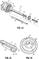
- Drive bar 148 defines a notch 151 therein towards the proximal end thereof that is configured, in conjunction with a drive bar support member 153 and return washer 155, to facilitate operable coupling of drive bar 148 with proximal sleeve 141.
- Drive assembly 140 further includes a support tube 158 disposed about drive bar 148.
- Support tube 158 extends about drive bar 148 but defines a shorter length than drive bar 148 such that the distal end of support tube 158 is position proximally of arm 149 and such that the proximal end of support tube 158 is positioned distally of notch 151.
- Support tube 158 defines a proximal slot 159a and a distal slot 159b.
- Support tube 158 and drive bar 148 are configured for receipt within a channel defined within inner guide tube 86 of elongated shaft assembly 80 (see FIG. 5 ).
- drive bar support member 153 defines a drive bar channel 154a configured to receive a portion of drive bar 148, a energizable member channel 154b configured to slidably receive a portion of energizable member 220 (see FIG. 21 ), a knife bar channel 154c configured to slidably receive a portion of knife bar 162 (see FIG. 21 ), and an elongated protrusion 154d defining a generally rectangular configuration.
- Drive bar support member 153 may further define a wire guide channel 154e configured to receive the wires (not shown) extending to jaw members 110, 120 of end effector assembly 100 ( FIGS. 2 and 3 ).
- return washer 155 defines a central aperture 156a and a locking finger 156b extending inwardly into central aperture 156a.
- proximal sleeve 141 defines a cantilever spring arm 157a towards the distal end thereof, an elongated slot 157b defined within cantilever spring arm 157a and shaped complementary to elongated protrusion 154d of drive bar support member 153, and a semi-annular slot 157c disposed at the fixed end of cantilever spring arm 157a.
- FIGS. 14 and 17-21 in order to operably couple drive bar 148 with proximal sleeve 141, the proximal end of drive bar 148 is inserted into drive bar channel 154a of drive bar support member 153 such that notch 151 and the open portion of drive bar channel 154a are oriented in similar directions, as shown in FIG. 17 .
- return washer 155 is slid proximally about proximal sleeve 141 such that proximal sleeve 141 extends through central aperture 156a of return washer 155.
- return washer 155 is slid proximally about proximal sleeve 141 (deflecting cantilever spring arm 157a inwardly at least initially), with proximal sleeve 141 extending through central aperture 156a of return washer 155 until locking finger 156b passes proximally though elongated slot 157b of proximal sleeve 141 and into semi-annular slot 157c of proximal sleeve 141 (see FIG. 18 ).
- drive bar 148 and drive bar support member 153 are advanced proximally into proximal sleeve 141 and towards return washer 155 such that cantilever spring arm 157a is flexed outwardly.
- Drive bar 148 and drive bar support member 153 are moved further proximally until elongated protrusion 154d of drive bar support member 153 abuts locking finger 156b of return washer 155. At this point, cantilever spring arm 157a remains outwardly-flexed.
- return washer 155 is rotated relative to proximal sleeve 141, drive bar 148, and drive bar support member 153 such that locking finger 156b moves through semi-annular slot 157c of proximal sleeve 141.
- Return washer 155 is rotated, as indicated by arrow "R" ( FIG. 19 ), to the end of semi-annular slot 157c, such that locking finger 156b is slid into notch 151 of drive bar 148, thereby engaging drive bar 148 and return washer 155.
- drive bar support member 153 may then be moved proximally relative to proximal sleeve 141 until elongated slot 157b defined within cantilever spring arm 157a is aligned with elongated protrusion 154d, thus allowing cantilever spring arm 157a to return inwardly under bias so as to capture elongated protrusion 154d within elongated slot 157b to engage drive bar support member 153 with proximal sleeve 141.
- drive assembly 140 further includes a biasing member 146 configured for positioning between return washer 155 and rotation wheel 72 of rotation assembly 70 so as to bias drive assembly 140 proximally.
- the proximal bias of drive assembly 140 biases movable handle towards the initial position. Moving movable handle 40 relative to fixed handle 50 from the initial position to the compressed position urges mandrel 144 distally. During initial movement of movable handle 40, distal movement of mandrel 144 urges biasing member 146 distally which, in turn, moves clip 145, proximal sleeve 141, drive bar 148, drive bar support member 153, and return washer 155 distally.
- trigger 62 of trigger assembly 60 is selectively actuatable relative to housing 20 from an un-actuated position to an actuated position. More specifically, trigger 62 includes an intermediate portion 63 having a split pivot 64 about which trigger 62 is pivotably coupled to housing 20 on either side of housing 20. A toggle portion 65 of trigger 62 extends from split pivot 64 in a first direction, ultimately exiting housing 20 to facilitate manipulation of trigger 62 from the exterior of housing 20. A bifurcated portion 66 of trigger 62 extends from split pivot 64 in a second, opposite direction further into housing 20. Bifurcated portion 66 of trigger 62 includes a pair of spaced-apart arms 67 interconnected via a transverse pin 68.
- knife assembly 160 is operably coupled to trigger 62 such that actuation of trigger 62 from the un-actuated position to the actuated position translates knife 164 of knife assembly 160 from a retracted position, wherein knife 164 is disposed proximally of jaw members 110, 120, to an extended position, wherein knife 164 extends at least partially between jaw members 110, 120 and through the knife channel(s) 126 ( FIG. 12 ) thereof to cut tissue grasped between jaw members 110, 120.
- Knife assembly 160 includes knife bar 162, knife 164, and a knife collar 166.
- Knife collar 166 is coaxial with mandrel assembly 142 and proximal sleeve 141 of drive assembly 140 (see FIG. 5 ); however knife bar 162, as noted above, extends along-side drive bar 148 (see FIG. 9 ) in non-coaxial, non-concentric orientation relative thereto.
- Knife 164 is engaged to and extends distally from knife bar 162. Knife 164 defines a sharpened distal cutting edge to facilitate cutting tissue, although other configurations are also contemplated.
- Knife bar 162 extends proximally from knife 164 and is configured for receipt within a channel defined within inner guide tube 86 of elongated shaft assembly 80 (see FIG. 5 ) such that knife bar 162 extends alongside drive bar 148, spaced-apart therefrom. Knife bar 162 extends further proximally from inner guide tube 86 for receipt within knife bar channel 154c of drive bar support member 153 and through proximal sleeve 141 of drive assembly 140. Knife bar 162 defines a proximal foot 163a that extends through an elongated cut-out 163b defined within proximal sleeve 141 (see FIG. 10 ).
- Knife collar 166 is slidably disposed about proximal sleeve 141 of drive assembly 140.
- Proximal foot 163a of knife bar 162 extends through elongated cut-out 163b of proximal sleeve, as mentioned above, and is received within an annular slot 167 defined within knife collar 166 to rotatably engage knife collar 166 about the proximal end of knife bar 162 with proximal sleeve 141 of drive assembly 140 disposed therebetween.
- Knife collar 166 further defines a transverse aperture 168 configured to receive transverse pin 68 of trigger assembly 60 to operably couple trigger assembly 60 and knife assembly 160 with one another.
- toggle portion 65 of trigger is pivoted about split pivot 64 in a generally proximal direction while bifurcated portion 66 is pivoted about split pivot 64 in a generally distal direction.
- Such distal movement of bifurcated portion 66 of trigger 62 urges transverse pin 68 distally, thereby urging knife collar 166 distally.
- a biasing member (not shown) configured to bias trigger 62 towards the un-actuated position and, thus, knife 164 towards the retracted position, may be provided.
- rotation assembly 70 includes rotation wheel 72 that is rotatably disposed but longitudinally constrained within a vertically-oriented slot 26 defined within housing 20 (see FIG. 1 ).
- Rotation wheel 72 extends at least partially through slots 26 on either side of housing 20 to enable manipulation of rotation wheel 72 on either exterior side of housing 20 (see FIG. 1 ).
- Rotation wheel 72 is engaged about inner proximal tube 83 of elongated shaft assembly 80 such that, as mentioned above, rotation of rotation wheel 72 effects corresponding rotation of inner proximal tube 83, inner distal tube 84, inner tube guide 86, end effector assembly 100, drive assembly 140, knife assembly 160, and monopolar assembly 200 relative to housing 20 ( FIG. 1 ) and fixed outer tube 82.
- Rotation assembly 70 further includes an engagement ferrule 74, an engagement clip 76, and a retainer 78 that, as detailed below, cooperate to enable engagement of rotation wheel 72 and fixed outer tube 82 without the need for precision joining, such as welding, while ensuring accurate placement of rotation wheel 72 on inner proximal tube 83 of elongated shaft assembly 80.
- This positioning is important to ensure proper spacing of rotation wheel 72 relative to end effector assembly 100 such that the proper positionings, clearances, and/or ranges of motions of the various components extending through elongated shaft assembly 80 to end effector assembly 100 are achieved.
- Rotation wheel 72 as shown in FIG. 26 , includes a body 73a having a manipulation portion 73b and a hub portion 73c and defines an aperture 73d extending therethrough.
- Manipulation portion 73b extends at least partially through slots 26 on either side of housing 20 to enable manipulation of rotation wheel 72.
- Hub portion 73c includes a raised block 73e extending inwardly into aperture 73d.
- Engagement ferrule 74 includes a sleeve body 75a defining a lumen 75b extending therethrough.
- a longitudinal slot 75c having an open proximal end and a closed distal end is defined through the outer surface of sleeve body 75a.
- Longitudinal slot 75c defines an enlarged locking portion 75d towards the closed distal end thereof.
- Longitudinal slot 75c is configured to receive raised block 73e of hub portion 73c of rotation wheel 72, as detailed below.
- Engagement ferrule 74 further defines an annular recess 75e and a window 75f extending through a portion of annular recess 75e into the interior of sleeve body 75a. Annular recess 75e and window 75f are disposed distally of longitudinal slot 75c.
- Engagement clip 76 defines a disc-shaped body 77a having an irregular aperture 77b extending therethrough.
- a tab 77c extends from disc-shaped body 77a into irregular aperture 77b.
- Retainer 78 defines a disc-shaped body 79a configured similar to or slightly larger than disc-shaped body 77a of engagement clip 76 ( FIG. 25 ).
- Disc-shaped body 79a defines an aperture 79b therethrough and includes a plurality of spaced-apart tabs 79c extending inwardly into aperture 79b.
- Tabs 79c may be equally-spaced annularly about aperture 79b, as shown in FIG. 24 , or may define any other suitable configuration.
- Retainer 78 further includes a collar 79d disposed about the outer periphery of disc-shaped body 79a. Collar 79d, as detailed below, is configured to surround disc-shaped body 77a of engagement clip 76 ( FIG. 25 ) so as to engage retainer about engagement clip 76 ( FIG. 25 ) with disc-shaped bodies 77a ( FIG. 25 ), 79a adjacent one another.
- FIGS. 22-29 the assembly of rotation wheel 72 on inner proximal tube 83 of elongated shaft assembly 80 is detailed.
- engagement ferrule 74 is inserted into aperture 73d of rotation wheel 72 with raised block 73e of rotation wheel 72 aligned with longitudinal slot 75c of engagement ferrule 74.
- sleeve body 75a is deflected so as to enlarge longitudinal slot 75c and enable passage of raised block 73e therethrough.
- inner proximal tube 83 of elongated shaft assembly 80 is translated proximally through aperture 79b of retainer 78, irregular aperture 77b of engagement clip 76, and into engagement ferrule 74 such that window 88 defined through inner proximal tube 83 is aligned with window 75f defined within engagement ferrule 74.
- engagement clip 76 is translated proximally about inner proximal tube 83 and engagement ferrule 74 until tab 77c is aligned above windows 75f, 88, as shown in FIG. 27 .
- engagement clip 76 is moved transversely relative to inner proximal tube 83 and engagement ferrule 74 such that tab 77c extends through windows 75f, 88, thereby engaging inner proximal tube 83 and engagement ferrule 74 with one another, as shown in FIG. 28 .
- retainer 78 is slid proximally about inner proximal tube 83 and engagement ferrule 74 until collar 79d of retainer 78 is engaged about disc-shaped body 77a of engagement clip 76 to inhibit engagement clip 76 from backing-out of engagement with inner proximal tube 83 and engagement ferrule 74.
- FIGS. 30-32 another configuration for assembling rotation wheel 72 on inner proximal tube 83 of elongated shaft assembly 80 is detailed. More specifically, in the configuration illustrated in FIGS. 30-32 , rather than using engagement clip 76 and retainer 78 (see FIG. 23 ), a G-clip 476 is utilized.
- G-clip 476 includes a body 477a defining a pair of semi-annular cantilever arms 477b, 477c. The free ends of arms 477b, 477c define a gap 477d therebetween.
- Body 477a further defines a window 477e towards the fixed ends of arms 477b, 477c.
- a hand 477f including three spaced-apart fingers 477g, 477h, 477i extends from body 477a into window 477e between arms 477b, 477c.
- G-clip 476 Assembly using G-clip 476 is initially similar to that detailed above. That is, engagement ferrule 74 is first engaged with rotation wheel 72, and then inner proximal tube 83 of elongated shaft assembly 80 is inserted into engagement ferrule 74 such that window 88 defined through inner proximal tube 83 is aligned with window 75f defined within engagement ferrule 74. Once this position has been achieved, G-clip 476 is inserted about engagement ferrule 74 transversely. That is, G-clip 476 is urged transversely about engagement ferrule 74 such that engagement ferrule 74 urges cantilever arms 477b, 477c outwardly relative to one another to widen gap 477d and permit insertion of engagement ferrule 74 therethrough.
- G-clip 476 is moved further transversely relative to engagement ferrule 74 such that middle finger 477h of hand 477f extends through windows 75f, 88, thereby engaging inner proximal tube 83 and engagement ferrule 74 with one another.
- the inward bias of arms 477b, 477c into contact with engagement ferrule 74 retains G-clip 476 about engagement ferrule 74, while outer fingers 477g and 477i are biased inwardly into engagement within annular recess 75e of engagement ferrule 74 to retain middle finger 477h in engagement with windows 75f, 88. This completes the assembly of rotation wheel 72 to inner proximal tube 83 using G-clip 476.
- monopolar assembly 200 includes an insulative sheath 210 and an energizable member 220.
- Insulative sheath 210 defines a body portion 217 and an enlarged-diametered distal portion 218 extending distally from body portion 217.
- An annular step 219 is defined at the interface between body portion 217 and enlarged-diametered distal portion 218 of insulative sheath 210.
- Insulative sheath 210 is movable relative to end effector assembly 100 between a storage position, wherein insulative sheath 210 is disposed proximally of end effector assembly 100, and a use position, wherein insulative sheath 210 is substantially disposed about end effector assembly 100.
- Energizable member 220 of monopolar assembly 200 includes a proximal cap 222, a bar 224, and an energizable element 226.
- Proximal cap 222 is engaged to bar 224 at the proximal end thereof and is operably engaged with deployment and retraction mechanism 300 for selectively deploying and retracting monopolar assembly 200.
- Bar 224 extends from proximal cap 222 distally through housing 20.
- Energizable element 226 extends through proximal bar 224 and distally therefrom to a distal tissue-treating portion 227.
- Energizable element 226 is coupled to the source of energy (not shown) and monopolar activation assembly 180 ( FIG. 5 ) via one or more wires (not shown).
- Distal tissue-treating portion 227 of energizable element 226 of energizable member 220 functions as the active electrode of monopolar assembly 200.
- Distal tissue-treating portion 227 may be hook-shaped (as shown), or may define any other suitable configuration, e.g., linear, ball, circular, angled, etc.
- Proximal bar 224 is insulated so as to facilitate the electrical insulation of energizable element 226 from its surroundings.
- Energizable member 220 slidably extends through a channel defined within inner guide tube 86 of elongated shaft assembly 80 (see FIG. 5 ) and energizable member channel 154b of drive bar support member 153 (see FIG. 21 ).
- energizable member 220 is disposed on the inner-edge side of jaw members 110, 120 of end effector assembly 100 and is movable relative thereto between a storage position, wherein distal tissue-treating portion 227 of energizable member 220 is positioned more-proximally, and a use position, wherein distal tissue-treating portion 227 of energizable member 220 extends distally from end effector assembly 100 to facilitate treating tissue therewith.
- insulative sheath 210 serves to electrically insulate end effector assembly 100 from distal tissue-treating portion 227 of energizable member 220, while distal tissue-treating portion 227 extends distally from end effector assembly 100. Further, in the use position, energy may be supplied to distal tissue-treating portion 227 of energizable member 220, e.g., via activation of either of the activation switches 182 of monopolar activation assembly 180 ( FIG. 1 ), for treating tissue in the monopolar mode of operation.
- energizable member 220 is engaged with insulative sleeve 210 such that energizable member 220 and insulative sleeve 210 move together between their respective storage and use positions.
- proximal cap 222 of energizable member 220 is operably coupled to deployment and retraction mechanism 300, thus enabling deployment and retraction mechanism 300 to translate insulative sheath 210 and energizable member 220 between their respective storage positions, collectively the storage condition of monopolar assembly 200, and their respective use conditions, collectively the use condition of monopolar assembly 200.
- Inner proximal and distal tubes 483, 484 of elongated shaft assembly 80 is shown.
- Inner proximal and distal tubes 483, 484 are similar to respective inner proximal and distal tubes 83, 84 ( FIG. 5 ), except that inner proximal and distal tubes 483, 484 include cut-outs 485, 486 so as to define C-shaped configurations.
- the C-shaped configurations of inner proximal and distal tubes 483, 484 and, more specifically, cut-outs 485, 486 thereof, allow for additional spacing to accommodate all of the components extending therethrough. For example, as shown in FIGS.
- energizable member 220 may extend through elongated shaft assembly 80 at least partially within cut-outs 485, 486, rather than being required to be fully disposed within the interior of inner proximal and distal tubes 483, 484. Referring to FIG. 40 , this configuration enables movement of energizable member 220 further outwardly relative from the position indicated by the phantom energizable member 220'.
- instrument 10 provides the further benefit of permitting deployment and retraction of monopolar assembly 200 ( FIG. 2 ) between the storage condition and the use condition even when elongated shaft assembly 80 is bent off-axis.
- instrument 10 provides the further benefit of permitting deployment and retraction of monopolar assembly 200 ( FIG. 2 ) between the storage condition and the use condition even when elongated shaft assembly 80 is bent off-axis.
- a trocar not shown
- surgeon is attempting to manipulate instrument 10 to a desired position.
- bending of elongated shaft assembly 80 up to about 35 degrees off-axis is permitted without limiting deployment and retraction of monopolar assembly 200 ( FIG. 2 ).
- Manipulation of end effector assembly 100 and deployment of knife 164 ( FIG. 5 ) may likewise be effected without limitation when elongated shaft assembly 80 is bent off-axis up to about 35 degrees.
- the various embodiments disclosed herein may also be configured to work with robotic surgical systems and what is commonly referred to as "Telesurgery.”
- Such systems employ various robotic elements to assist the surgeon in the operating room and allow remote operation (or partial remote operation) of surgical instrumentation.
- Various robotic arms, gears, cams, pulleys, electric and mechanical motors, etc. may be employed for this purpose and may be designed with a robotic surgical system to assist the surgeon during the course of an operation or treatment.
- Such robotic systems may include remotely steerable systems, automatically flexible surgical systems, remotely flexible surgical systems, remotely articulating surgical systems, wireless surgical systems, modular or selectively configurable remotely operated surgical systems, etc.
- the robotic surgical systems may be employed with one or more consoles that are next to the operating theater or located in a remote location.
- one team of surgeons or nurses may prep the patient for surgery and configure the robotic surgical system with one or more of the instruments disclosed herein while another surgeon (or group of surgeons) remotely control the instruments via the robotic surgical system.
- a highly skilled surgeon may perform multiple operations in multiple locations without leaving his/her remote console which can be both economically advantageous and a benefit to the patient or a series of patients.
- the robotic arms of the surgical system are typically coupled to a pair of master handles by a controller.
- the handles can be moved by the surgeon to produce a corresponding movement of the working ends of any type of surgical instrument (e.g., end effectors, graspers, knifes, scissors, etc.) which may complement the use of one or more of the embodiments described herein.
- the movement of the master handles may be scaled so that the working ends have a corresponding movement that is different, smaller or larger, than the movement performed by the operating hands of the surgeon.
- the scale factor or gearing ratio may be adjustable so that the operator can control the resolution of the working ends of the surgical instrument(s).
- the master handles may include various sensors to provide feedback to the surgeon relating to various tissue parameters or conditions, e.g., tissue resistance due to manipulation, cutting or otherwise treating, pressure by the instrument onto the tissue, tissue temperature, tissue impedance, etc. As can be appreciated, such sensors provide the surgeon with enhanced tactile feedback simulating actual operating conditions.
- the master handles may also include a variety of different actuators for delicate tissue manipulation or treatment further enhancing the surgeon's ability to mimic actual operating conditions.
Applications Claiming Priority (1)
| Application Number | Priority Date | Filing Date | Title |
|---|---|---|---|
| US15/055,260 US10537381B2 (en) | 2016-02-26 | 2016-02-26 | Surgical instrument having a bipolar end effector assembly and a deployable monopolar assembly |
Publications (2)
| Publication Number | Publication Date |
|---|---|
| EP3210559A1 true EP3210559A1 (de) | 2017-08-30 |
| EP3210559B1 EP3210559B1 (de) | 2019-04-17 |
Family
ID=58094324
Family Applications (1)
| Application Number | Title | Priority Date | Filing Date |
|---|---|---|---|
| EP17156975.9A Active EP3210559B1 (de) | 2016-02-26 | 2017-02-20 | Chirurgisches instrument mit bipolarer endeffektoranordnung und entfaltbarer monopolarer anordnung |
Country Status (2)
| Country | Link |
|---|---|
| US (1) | US10537381B2 (de) |
| EP (1) | EP3210559B1 (de) |
Cited By (1)
| Publication number | Priority date | Publication date | Assignee | Title |
|---|---|---|---|---|
| EP3449849B1 (de) * | 2017-08-29 | 2023-07-19 | Covidien LP | Chirurgische instrumente und system zum zusammenbau chirurgischer instrumente |
Families Citing this family (61)
| Publication number | Priority date | Publication date | Assignee | Title |
|---|---|---|---|---|
| US7845537B2 (en) | 2006-01-31 | 2010-12-07 | Ethicon Endo-Surgery, Inc. | Surgical instrument having recording capabilities |
| US8465502B2 (en) | 2008-08-25 | 2013-06-18 | Covidien Lp | Surgical clip applier and method of assembly |
| US9358015B2 (en) | 2008-08-29 | 2016-06-07 | Covidien Lp | Endoscopic surgical clip applier with wedge plate |
| US8267944B2 (en) | 2008-08-29 | 2012-09-18 | Tyco Healthcare Group Lp | Endoscopic surgical clip applier with lock out |
| US9186136B2 (en) | 2009-12-09 | 2015-11-17 | Covidien Lp | Surgical clip applier |
| US8403945B2 (en) | 2010-02-25 | 2013-03-26 | Covidien Lp | Articulating endoscopic surgical clip applier |
| US8968337B2 (en) | 2010-07-28 | 2015-03-03 | Covidien Lp | Articulating clip applier |
| US9629814B2 (en) | 2010-09-30 | 2017-04-25 | Ethicon Endo-Surgery, Llc | Tissue thickness compensator configured to redistribute compressive forces |
| US20130131697A1 (en) | 2011-11-21 | 2013-05-23 | Covidien Lp | Surgical clip applier |
| US9364216B2 (en) | 2011-12-29 | 2016-06-14 | Covidien Lp | Surgical clip applier with integrated clip counter |
| US9408610B2 (en) | 2012-05-04 | 2016-08-09 | Covidien Lp | Surgical clip applier with dissector |
| US9532787B2 (en) | 2012-05-31 | 2017-01-03 | Covidien Lp | Endoscopic clip applier |
| US9113892B2 (en) | 2013-01-08 | 2015-08-25 | Covidien Lp | Surgical clip applier |
| JP6382235B2 (ja) | 2013-03-01 | 2018-08-29 | エシコン・エンド−サージェリィ・インコーポレイテッドEthicon Endo−Surgery,Inc. | 信号通信用の導電路を備えた関節運動可能な外科用器具 |
| US9775624B2 (en) | 2013-08-27 | 2017-10-03 | Covidien Lp | Surgical clip applier |
| US9931124B2 (en) | 2015-01-07 | 2018-04-03 | Covidien Lp | Reposable clip applier |
| CN107205747B (zh) | 2015-01-15 | 2020-09-08 | 柯惠有限合伙公司 | 可重复使用的内窥镜外科夹具施加器 |
| US10292712B2 (en) | 2015-01-28 | 2019-05-21 | Covidien Lp | Surgical clip applier with integrated cutter |
| US10159491B2 (en) | 2015-03-10 | 2018-12-25 | Covidien Lp | Endoscopic reposable surgical clip applier |
| USD844138S1 (en) * | 2015-07-17 | 2019-03-26 | Covidien Lp | Handle assembly of a multi-function surgical instrument |
| USD844139S1 (en) * | 2015-07-17 | 2019-03-26 | Covidien Lp | Monopolar assembly of a multi-function surgical instrument |
| JP6683807B2 (ja) | 2015-10-10 | 2020-04-22 | コヴィディエン リミテッド パートナーシップ | 内視鏡外科用クリップアプライヤ |
| JP6626197B2 (ja) | 2015-11-03 | 2019-12-25 | コヴィディエン リミテッド パートナーシップ | 内視鏡外科用クリップアプライヤ |
| CA2999906A1 (en) | 2015-11-10 | 2017-05-18 | Covidien Lp | Endoscopic reposable surgical clip applier |
| US10390831B2 (en) | 2015-11-10 | 2019-08-27 | Covidien Lp | Endoscopic reposable surgical clip applier |
| CA2999907A1 (en) | 2015-11-10 | 2017-05-18 | Covidien Lp | Endoscopic reposable surgical clip applier |
| AU2016386597A1 (en) | 2016-01-11 | 2018-07-05 | Covidien Lp | Endoscopic reposable surgical clip applier |
| CA3011262A1 (en) | 2016-01-18 | 2017-07-27 | Covidien Lp | Endoscopic surgical clip applier |
| CA2958160A1 (en) | 2016-02-24 | 2017-08-24 | Covidien Lp | Endoscopic reposable surgical clip applier |
| US10806464B2 (en) | 2016-08-11 | 2020-10-20 | Covidien Lp | Endoscopic surgical clip applier and clip applying systems |
| US10660651B2 (en) | 2016-10-31 | 2020-05-26 | Covidien Lp | Endoscopic reposable surgical clip applier |
| US10639044B2 (en) | 2016-10-31 | 2020-05-05 | Covidien Lp | Ligation clip module and clip applier |
| US10863992B2 (en) | 2017-08-08 | 2020-12-15 | Covidien Lp | Endoscopic surgical clip applier |
| US10932790B2 (en) | 2017-08-08 | 2021-03-02 | Covidien Lp | Geared actuation mechanism and surgical clip applier including the same |
| US10786262B2 (en) | 2017-08-09 | 2020-09-29 | Covidien Lp | Endoscopic reposable surgical clip applier |
| US10786263B2 (en) | 2017-08-15 | 2020-09-29 | Covidien Lp | Endoscopic reposable surgical clip applier |
| US10835341B2 (en) | 2017-09-12 | 2020-11-17 | Covidien Lp | Endoscopic surgical clip applier and handle assemblies for use therewith |
| WO2019071269A2 (en) | 2017-10-06 | 2019-04-11 | Powell Charles Lee | SYSTEM AND METHOD FOR TREATING AN OBSTRUCTIVE SLEEP APNEA |
| US10842490B2 (en) | 2017-10-31 | 2020-11-24 | Ethicon Llc | Cartridge body design with force reduction based on firing completion |
| US10932791B2 (en) | 2017-11-03 | 2021-03-02 | Covidien Lp | Reposable multi-fire surgical clip applier |
| US10945734B2 (en) | 2017-11-03 | 2021-03-16 | Covidien Lp | Rotation knob assemblies and surgical instruments including the same |
| US11376015B2 (en) | 2017-11-03 | 2022-07-05 | Covidien Lp | Endoscopic surgical clip applier and handle assemblies for use therewith |
| US11116513B2 (en) | 2017-11-03 | 2021-09-14 | Covidien Lp | Modular surgical clip cartridge |
| US10849630B2 (en) | 2017-12-13 | 2020-12-01 | Covidien Lp | Reposable multi-fire surgical clip applier |
| US10743887B2 (en) | 2017-12-13 | 2020-08-18 | Covidien Lp | Reposable multi-fire surgical clip applier |
| US11051827B2 (en) | 2018-01-16 | 2021-07-06 | Covidien Lp | Endoscopic surgical instrument and handle assemblies for use therewith |
| AU2019217523B2 (en) * | 2018-02-06 | 2021-09-09 | Conmed Corporation | Force limiting assembly for surgical instrument |
| US10993721B2 (en) | 2018-04-25 | 2021-05-04 | Covidien Lp | Surgical clip applier |
| US10786273B2 (en) | 2018-07-13 | 2020-09-29 | Covidien Lp | Rotation knob assemblies for handle assemblies |
| US11259887B2 (en) | 2018-08-10 | 2022-03-01 | Covidien Lp | Feedback mechanisms for handle assemblies |
| US11051828B2 (en) | 2018-08-13 | 2021-07-06 | Covidien Lp | Rotation knob assemblies and surgical instruments including same |
| US11253267B2 (en) | 2018-08-13 | 2022-02-22 | Covidien Lp | Friction reduction mechanisms for handle assemblies |
| US11278267B2 (en) | 2018-08-13 | 2022-03-22 | Covidien Lp | Latch assemblies and surgical instruments including the same |
| US11033256B2 (en) | 2018-08-13 | 2021-06-15 | Covidien Lp | Linkage assembly for reusable surgical handle assemblies |
| US20200054321A1 (en) * | 2018-08-20 | 2020-02-20 | Ethicon Llc | Surgical instruments with progressive jaw closure arrangements |
| US11147566B2 (en) | 2018-10-01 | 2021-10-19 | Covidien Lp | Endoscopic surgical clip applier |
| US11524398B2 (en) | 2019-03-19 | 2022-12-13 | Covidien Lp | Gear drive mechanisms for surgical instruments |
| US20200305910A1 (en) | 2019-03-29 | 2020-10-01 | Gyrus Acmi, Inc. D/B/A Olympus Surgical Thechnologies America | Forceps including rotationally locked shafts |
| US11779340B2 (en) | 2020-01-02 | 2023-10-10 | Covidien Lp | Ligation clip loading device |
| US11723669B2 (en) | 2020-01-08 | 2023-08-15 | Covidien Lp | Clip applier with clip cartridge interface |
| US20230050248A1 (en) * | 2021-08-10 | 2023-02-16 | Covidien Lp | Shaft retention features for shaft-based surgical instruments |
Citations (7)
| Publication number | Priority date | Publication date | Assignee | Title |
|---|---|---|---|---|
| US20070106295A1 (en) * | 2005-09-30 | 2007-05-10 | Garrison David M | Insulating boot for electrosurgical forceps |
| US20110009863A1 (en) * | 2009-07-10 | 2011-01-13 | Tyco Healthcare Group Lp | Shaft Constructions for Medical Devices with an Articulating Tip |
| EP2316367A1 (de) * | 2004-10-21 | 2011-05-04 | Covidien AG | Bipolare elektrochirurgische Zange mit monopolaren Erweiterungselement |
| US20140025071A1 (en) | 2012-05-01 | 2014-01-23 | Covidien Lp | Simplified spring load mechanism for delivering shaft force of a surgical instrument |
| US20140257274A1 (en) | 2013-03-11 | 2014-09-11 | Covidien Lp | Surgical instrument |
| EP2853221A1 (de) * | 2013-09-25 | 2015-04-01 | Covidien LP | Multifunktionelle chirurgische Instrumente |
| EP2982326A1 (de) * | 2013-03-11 | 2016-02-10 | Covidien LP | Chirurgisches instrument mit schalteraktivierungssteuerung |
Family Cites Families (343)
| Publication number | Priority date | Publication date | Assignee | Title |
|---|---|---|---|---|
| SU401367A1 (ru) | 1971-10-05 | 1973-10-12 | Тернопольский государственный медицинский институт | Биактивный электрохирургическнп инструмент |
| DE2415263A1 (de) | 1974-03-29 | 1975-10-02 | Aesculap Werke Ag | Chirurgische hf-koagulationssonde |
| DE2514501A1 (de) | 1975-04-03 | 1976-10-21 | Karl Storz | Bipolares coagulationsinstrument fuer endoskope |
| US4005714A (en) | 1975-05-03 | 1977-02-01 | Richard Wolf Gmbh | Bipolar coagulation forceps |
| FR2315286A2 (fr) | 1975-06-26 | 1977-01-21 | Lamidey Marcel | Pince a dissequer, hemostatique, haute frequence |
| USD249549S (en) | 1976-10-22 | 1978-09-19 | Aspen Laboratories, Inc. | Electrosurgical handle |
| USD263020S (en) | 1980-01-22 | 1982-02-16 | Rau Iii David M | Retractable knife |
| JPS61501068A (ja) | 1984-01-30 | 1986-05-29 | ハルコフスキイ ナウチノ−イススレドワテルスキイ インスチチユ−ト オブスチエイ イ ネオトロジノイ ヒルルギイ | 二極性電気外科用器械 |
| DE3423356C2 (de) | 1984-06-25 | 1986-06-26 | Berchtold Medizin-Elektronik GmbH & Co, 7200 Tuttlingen | Elektrochirurgisches Hochfrequenz-Schneidinstrument |
| US4657016A (en) | 1984-08-20 | 1987-04-14 | Garito Jon C | Electrosurgical handpiece for blades, needles and forceps |
| USD299413S (en) | 1985-07-17 | 1989-01-17 | The Stanley Works | Folding pocket saw handle |
| USD295893S (en) | 1985-09-25 | 1988-05-24 | Acme United Corporation | Disposable surgical clamp |
| USD295894S (en) | 1985-09-26 | 1988-05-24 | Acme United Corporation | Disposable surgical scissors |
| USD298353S (en) | 1986-05-06 | 1988-11-01 | Vitalmetrics, Inc. | Handle for surgical instrument |
| DE8712328U1 (de) | 1987-09-11 | 1988-02-18 | Jakoubek, Franz, 7201 Emmingen-Liptingen, De | |
| US4799264A (en) | 1987-09-28 | 1989-01-17 | Plummer Jan P | Speaker system |
| US5026379A (en) | 1989-12-05 | 1991-06-25 | Inbae Yoon | Multi-functional instruments and stretchable ligating and occluding devices |
| US5919202A (en) | 1989-12-05 | 1999-07-06 | Yoon; Inbae | Surgical instrument with jaws and movable internal needle and method for use thereof |
| US5893863A (en) | 1989-12-05 | 1999-04-13 | Yoon; Inbae | Surgical instrument with jaws and movable internal hook member for use thereof |
| US5195958A (en) | 1990-05-25 | 1993-03-23 | Phillips Edward H | Tool for laparoscopic surgery |
| JP2806511B2 (ja) | 1990-07-31 | 1998-09-30 | 松下電工株式会社 | 合金系焼結体の製法 |
| US5389102A (en) | 1990-09-13 | 1995-02-14 | United States Surgical Corporation | Apparatus and method for subcuticular stapling of body tissue |
| JP2951418B2 (ja) | 1991-02-08 | 1999-09-20 | トキコ株式会社 | 試料液成分分析装置 |
| US5324289A (en) | 1991-06-07 | 1994-06-28 | Hemostatic Surgery Corporation | Hemostatic bi-polar electrosurgical cutting apparatus and methods of use |
| USD348930S (en) | 1991-10-11 | 1994-07-19 | Ethicon, Inc. | Endoscopic stapler |
| US5318589A (en) | 1992-04-15 | 1994-06-07 | Microsurge, Inc. | Surgical instrument for endoscopic surgery |
| US5620459A (en) | 1992-04-15 | 1997-04-15 | Microsurge, Inc. | Surgical instrument |
| JPH05293115A (ja) | 1992-04-20 | 1993-11-09 | Olympus Optical Co Ltd | 高周波処置具 |
| JPH0630945A (ja) | 1992-05-19 | 1994-02-08 | Olympus Optical Co Ltd | 縫合器 |
| US5312391A (en) | 1992-07-29 | 1994-05-17 | Wilk Peter J | Laparoscopic instrument assembly |
| CA2106126A1 (en) | 1992-09-23 | 1994-03-24 | Ian M. Scott | Bipolar surgical instruments |
| US5411519A (en) | 1992-09-23 | 1995-05-02 | United States Surgical Corporation | Surgical apparatus having hinged jaw structure |
| USD349341S (en) | 1992-10-28 | 1994-08-02 | Microsurge, Inc. | Endoscopic grasper |
| DE4242143C2 (de) | 1992-12-14 | 2001-04-12 | Delma Elektro Med App | Hochfrequenzchirurgisches Handinstrument |
| US5807393A (en) | 1992-12-22 | 1998-09-15 | Ethicon Endo-Surgery, Inc. | Surgical tissue treating device with locking mechanism |
| US5342359A (en) | 1993-02-05 | 1994-08-30 | Everest Medical Corporation | Bipolar coagulation device |
| DE4303882C2 (de) | 1993-02-10 | 1995-02-09 | Kernforschungsz Karlsruhe | Kombinationsinstrument zum Trennen und Koagulieren für die minimal invasive Chirurgie |
| US5445638B1 (en) | 1993-03-08 | 1998-05-05 | Everest Medical Corp | Bipolar coagulation and cutting forceps |
| JP3390041B2 (ja) | 1993-04-05 | 2003-03-24 | オリンパス光学工業株式会社 | 鉗 子 |
| GB9309142D0 (en) | 1993-05-04 | 1993-06-16 | Gyrus Medical Ltd | Laparoscopic instrument |
| USD343453S (en) | 1993-05-05 | 1994-01-18 | Laparomed Corporation | Handle for laparoscopic surgical instrument |
| USD354564S (en) | 1993-06-25 | 1995-01-17 | Richard-Allan Medical Industries, Inc. | Surgical clip applier |
| US5688270A (en) | 1993-07-22 | 1997-11-18 | Ethicon Endo-Surgery,Inc. | Electrosurgical hemostatic device with recessed and/or offset electrodes |
| US5693051A (en) | 1993-07-22 | 1997-12-02 | Ethicon Endo-Surgery, Inc. | Electrosurgical hemostatic device with adaptive electrodes |
| US5368600A (en) | 1993-07-23 | 1994-11-29 | Ethicon, Inc. | Steerable bulldog clamp applier |
| GB9322464D0 (en) | 1993-11-01 | 1993-12-22 | Gyrus Medical Ltd | Electrosurgical apparatus |
| US5458598A (en) | 1993-12-02 | 1995-10-17 | Cabot Technology Corporation | Cutting and coagulating forceps |
| USD358887S (en) | 1993-12-02 | 1995-05-30 | Cobot Medical Corporation | Combined cutting and coagulating forceps |
| DE4403252A1 (de) | 1994-02-03 | 1995-08-10 | Michael Hauser | Instrumentenschaft für die minimalinvasive Chirurgie |
| GB9413070D0 (en) | 1994-06-29 | 1994-08-17 | Gyrus Medical Ltd | Electrosurgical apparatus |
| USD384413S (en) | 1994-10-07 | 1997-09-30 | United States Surgical Corporation | Endoscopic suturing instrument |
| US5556397A (en) | 1994-10-26 | 1996-09-17 | Laser Centers Of America | Coaxial electrosurgical instrument |
| US5792164A (en) | 1994-12-19 | 1998-08-11 | Lakatos; Nick | Surgical instrument |
| GB9425781D0 (en) | 1994-12-21 | 1995-02-22 | Gyrus Medical Ltd | Electrosurgical instrument |
| DE19506363A1 (de) | 1995-02-24 | 1996-08-29 | Frost Lore Geb Haupt | Verfahren zur nicht-invasiven Thermometrie in Organen unter medizinischen Hyperthermie- und Koagulationsbedingungen |
| JPH08289895A (ja) | 1995-04-21 | 1996-11-05 | Olympus Optical Co Ltd | 縫合器 |
| DE19515914C1 (de) | 1995-05-02 | 1996-07-25 | Aesculap Ag | Zangen- oder scherenförmiges chirurgisches Instrument |
| US6837888B2 (en) | 1995-06-07 | 2005-01-04 | Arthrocare Corporation | Electrosurgical probe with movable return electrode and methods related thereto |
| JPH09538A (ja) | 1995-06-21 | 1997-01-07 | Fuji Photo Optical Co Ltd | 高周波処置具 |
| US6293942B1 (en) | 1995-06-23 | 2001-09-25 | Gyrus Medical Limited | Electrosurgical generator method |
| BR9609421A (pt) | 1995-06-23 | 1999-05-18 | Gyrus Medical Ltd | Instrumento eletrocirúrgico |
| JPH1024051A (ja) | 1995-09-20 | 1998-01-27 | Olympus Optical Co Ltd | 切離機能付凝固鉗子 |
| USH1745H (en) | 1995-09-29 | 1998-08-04 | Paraschac; Joseph F. | Electrosurgical clamping device with insulation limited bipolar electrode |
| AU703455B2 (en) | 1995-10-20 | 1999-03-25 | Ethicon Endo-Surgery, Inc. | Self protecting knife for curved jaw surgical instruments |
| DE19608716C1 (de) | 1996-03-06 | 1997-04-17 | Aesculap Ag | Bipolares chirurgisches Faßinstrument |
| USD408018S (en) | 1996-03-12 | 1999-04-13 | Mcnaughton Patrick J | Switch guard |
| USD416089S (en) | 1996-04-08 | 1999-11-02 | Richard-Allan Medical Industries, Inc. | Endoscopic linear stapling and dividing surgical instrument |
| DE29616210U1 (de) | 1996-09-18 | 1996-11-14 | Winter & Ibe Olympus | Handhabe für chirurgische Instrumente |
| US5923475A (en) | 1996-11-27 | 1999-07-13 | Eastman Kodak Company | Laser printer using a fly's eye integrator |
| JP3836551B2 (ja) | 1996-12-04 | 2006-10-25 | ペンタックス株式会社 | 内視鏡用ホットバイオプシー鉗子 |
| US5931810A (en) | 1996-12-05 | 1999-08-03 | Comedicus Incorporated | Method for accessing the pericardial space |
| US5891142A (en) | 1996-12-06 | 1999-04-06 | Eggers & Associates, Inc. | Electrosurgical forceps |
| US5735873A (en) | 1996-12-19 | 1998-04-07 | Maclean; David S. | Surgical tool handle |
| US6113596A (en) | 1996-12-30 | 2000-09-05 | Enable Medical Corporation | Combination monopolar-bipolar electrosurgical instrument system, instrument and cable |
| USH2037H1 (en) | 1997-05-14 | 2002-07-02 | David C. Yates | Electrosurgical hemostatic device including an anvil |
| USH1904H (en) | 1997-05-14 | 2000-10-03 | Ethicon Endo-Surgery, Inc. | Electrosurgical hemostatic method and device |
| JP3986126B2 (ja) | 1997-08-04 | 2007-10-03 | オリンパス株式会社 | 内視鏡下手術器械 |
| JP3986127B2 (ja) | 1997-08-06 | 2007-10-03 | オリンパス株式会社 | 内視鏡下手術器械 |
| DE19738457B4 (de) | 1997-09-03 | 2009-01-02 | Celon Ag Medical Instruments | Verfahren und Vorrichtung für die In-vivo-Tiefenkoagulation biologischer Gewebevolumina bei gleichzeitiger Schonung der Gewebeoberfläche mit hochfrequentem Wechselstrom |
| US5980510A (en) | 1997-10-10 | 1999-11-09 | Ethicon Endo-Surgery, Inc. | Ultrasonic clamp coagulator apparatus having improved clamp arm pivot mount |
| USD402028S (en) | 1997-10-10 | 1998-12-01 | Invasatec, Inc. | Hand controller for medical system |
| DE19751108A1 (de) | 1997-11-18 | 1999-05-20 | Beger Frank Michael Dipl Desig | Elektrochirurgisches Operationswerkzeug |
| JPH11169381A (ja) | 1997-12-15 | 1999-06-29 | Olympus Optical Co Ltd | 高周波処置具 |
| EP0923907A1 (de) | 1997-12-19 | 1999-06-23 | Gyrus Medical Limited | Elektrochirurgisches Instrument |
| US5967997A (en) * | 1998-04-30 | 1999-10-19 | Symbiosis Corporation | Endoscopic surgical instrument with deflectable and rotatable distal end |
| US6679882B1 (en) | 1998-06-22 | 2004-01-20 | Lina Medical Aps | Electrosurgical device for coagulating and for making incisions, a method of severing blood vessels and a method of coagulating and for making incisions in or severing tissue |
| DE19836481C1 (de) | 1998-08-12 | 2000-03-30 | Storz Karl Gmbh & Co Kg | Handgriff für ein medizinisches Instrument |
| JP4225624B2 (ja) | 1998-08-27 | 2009-02-18 | オリンパス株式会社 | 高周波処置装置 |
| USD425201S (en) | 1998-10-23 | 2000-05-16 | Sherwood Services Ag | Disposable electrode assembly |
| USD449886S1 (en) | 1998-10-23 | 2001-10-30 | Sherwood Services Ag | Forceps with disposable electrode |
| AU756626B2 (en) | 1998-10-23 | 2003-01-16 | Covidien Ag | Open vessel sealing forceps with disposable electrodes |
| USD424694S (en) | 1998-10-23 | 2000-05-09 | Sherwood Services Ag | Forceps |
| DE19850068C1 (de) | 1998-10-30 | 2000-06-08 | Storz Karl Gmbh & Co Kg | Medizinisches Instrument zum Präparieren von Gewebe |
| DE19858512C1 (de) | 1998-12-18 | 2000-05-25 | Storz Karl Gmbh & Co Kg | Bipolares medizinisches Instrument |
| US6190386B1 (en) | 1999-03-09 | 2001-02-20 | Everest Medical Corporation | Electrosurgical forceps with needle electrodes |
| DE19915061A1 (de) | 1999-04-01 | 2000-10-26 | Erbe Elektromedizin | Chirurgisches Instrument |
| GB9911954D0 (en) | 1999-05-21 | 1999-07-21 | Gyrus Medical Ltd | Electrosurgery system and instrument |
| GB9911956D0 (en) | 1999-05-21 | 1999-07-21 | Gyrus Medical Ltd | Electrosurgery system and method |
| GB9912625D0 (en) | 1999-05-28 | 1999-07-28 | Gyrus Medical Ltd | An electrosurgical generator and system |
| GB9912627D0 (en) | 1999-05-28 | 1999-07-28 | Gyrus Medical Ltd | An electrosurgical instrument |
| GB9913652D0 (en) | 1999-06-11 | 1999-08-11 | Gyrus Medical Ltd | An electrosurgical generator |
| JP2001003400A (ja) | 1999-06-21 | 2001-01-09 | Sumitomo Constr Mach Co Ltd | 油圧ショベルのモニター装置 |
| JP2001029355A (ja) | 1999-07-21 | 2001-02-06 | Olympus Optical Co Ltd | 電気メス装置 |
| US6692445B2 (en) | 1999-07-27 | 2004-02-17 | Scimed Life Systems, Inc. | Biopsy sampler |
| DE19940689A1 (de) | 1999-08-27 | 2001-04-05 | Storz Karl Gmbh & Co Kg | Bipolares medizinisches Instrument |
| JP3721882B2 (ja) * | 1999-09-14 | 2005-11-30 | フジノン株式会社 | 内視鏡の挿入部 |
| USD465281S1 (en) | 1999-09-21 | 2002-11-05 | Karl Storz Gmbh & Co. Kg | Endoscopic medical instrument |
| DE19946527C1 (de) | 1999-09-28 | 2001-07-12 | Storz Karl Gmbh & Co Kg | Medizinisches bipolares Instrument zum Fassen, Koagulieren und Schneiden von Gewebe |
| JP4315557B2 (ja) | 2000-01-12 | 2009-08-19 | オリンパス株式会社 | 医療用処置具 |
| DE10003020C2 (de) | 2000-01-25 | 2001-12-06 | Aesculap Ag & Co Kg | Bipolares Faßinstrument |
| US6558385B1 (en) | 2000-09-22 | 2003-05-06 | Tissuelink Medical, Inc. | Fluid-assisted medical device |
| DE10031773B4 (de) | 2000-05-04 | 2007-11-29 | Erbe Elektromedizin Gmbh | Chirurgisches Greifinstrument, insbesondere Pinzette oder Zange |
| DE10027727C1 (de) | 2000-06-03 | 2001-12-06 | Aesculap Ag & Co Kg | Scheren- oder zangenförmiges chirurgisches Instrument |
| DE10045375C2 (de) | 2000-09-14 | 2002-10-24 | Aesculap Ag & Co Kg | Medizinisches Instrument |
| WO2002056748A2 (en) | 2000-10-20 | 2002-07-25 | Onux Medical, Inc. | Surgical suturing instrument and method of use |
| JP3523839B2 (ja) | 2000-10-30 | 2004-04-26 | オリンパス株式会社 | 手術器械 |
| USD453923S1 (en) | 2000-11-16 | 2002-02-26 | Carling Technologies, Inc. | Electrical rocker switch guard |
| DE10061278B4 (de) | 2000-12-08 | 2004-09-16 | GFD-Gesellschaft für Diamantprodukte mbH | Instrument für chirurgische Zwecke |
| US6554829B2 (en) | 2001-01-24 | 2003-04-29 | Ethicon, Inc. | Electrosurgical instrument with minimally invasive jaws |
| US6464702B2 (en) | 2001-01-24 | 2002-10-15 | Ethicon, Inc. | Electrosurgical instrument with closing tube for conducting RF energy and moving jaws |
| US20020111624A1 (en) | 2001-01-26 | 2002-08-15 | Witt David A. | Coagulating electrosurgical instrument with tissue dam |
| DE20121161U1 (de) | 2001-01-31 | 2002-04-04 | Winter & Ibe Olympus | Endoskopisches Instrument |
| USD466209S1 (en) | 2001-02-27 | 2002-11-26 | Visionary Biomedical, Inc. | Steerable catheter |
| USD454951S1 (en) | 2001-02-27 | 2002-03-26 | Visionary Biomedical, Inc. | Steerable catheter |
| US7473253B2 (en) | 2001-04-06 | 2009-01-06 | Covidien Ag | Vessel sealer and divider with non-conductive stop members |
| USD457958S1 (en) | 2001-04-06 | 2002-05-28 | Sherwood Services Ag | Vessel sealer and divider |
| USD457959S1 (en) | 2001-04-06 | 2002-05-28 | Sherwood Services Ag | Vessel sealer |
| US6551313B1 (en) | 2001-05-02 | 2003-04-22 | John M. Levin | Electrosurgical instrument with separate cutting and coagulating members |
| FR2828248B1 (fr) | 2001-08-02 | 2003-11-14 | Peugeot Citroen Automobiles Sa | Axe de liaison pivot entre deux pieces |
| US7208005B2 (en) | 2001-08-06 | 2007-04-24 | The Penn State Research Foundation | Multifunctional tool and method for minimally invasive surgery |
| US6808525B2 (en) | 2001-08-27 | 2004-10-26 | Gyrus Medical, Inc. | Bipolar electrosurgical hook probe for cutting and coagulating tissue |
| JP2003116871A (ja) | 2001-10-16 | 2003-04-22 | Olympus Optical Co Ltd | 処置具 |
| US6942662B2 (en) | 2001-12-27 | 2005-09-13 | Gyrus Group Plc | Surgical Instrument |
| US6676660B2 (en) | 2002-01-23 | 2004-01-13 | Ethicon Endo-Surgery, Inc. | Feedback light apparatus and method for use with an electrosurgical instrument |
| US7033356B2 (en) | 2002-07-02 | 2006-04-25 | Gyrus Medical, Inc. | Bipolar electrosurgical instrument for cutting desiccating and sealing tissue |
| DE60312348T2 (de) | 2002-10-04 | 2008-01-24 | Covidien Ag | Elektrodenanordnung zum versiegeln und schneiden von gewebe |
| US7270664B2 (en) | 2002-10-04 | 2007-09-18 | Sherwood Services Ag | Vessel sealing instrument with electrical cutting mechanism |
| JP2003175052A (ja) | 2002-11-01 | 2003-06-24 | Olympus Optical Co Ltd | 凝固処置具 |
| USD493888S1 (en) | 2003-02-04 | 2004-08-03 | Sherwood Services Ag | Electrosurgical pencil with pistol grip |
| USD499181S1 (en) | 2003-05-15 | 2004-11-30 | Sherwood Services Ag | Handle for a vessel sealer and divider |
| USD496997S1 (en) | 2003-05-15 | 2004-10-05 | Sherwood Services Ag | Vessel sealer and divider |
| USD502994S1 (en) | 2003-05-21 | 2005-03-15 | Blake, Iii Joseph W | Repeating multi-clip applier |
| JP4035100B2 (ja) | 2003-06-09 | 2008-01-16 | 徹 谷 | 医療用処置具及びこれを備えた医療用処置装置 |
| US7150749B2 (en) | 2003-06-13 | 2006-12-19 | Sherwood Services Ag | Vessel sealer and divider having elongated knife stroke and safety cutting mechanism |
| US7510562B2 (en) | 2003-07-08 | 2009-03-31 | Terumo Corporation | Vein dissector, cauterizing and ligating apparatus for endoscopic harvesting of blood vessels |
| USD545432S1 (en) | 2003-08-08 | 2007-06-26 | Olympus Corporation | Distal portion of hemostatic forceps for endoscope |
| USD509297S1 (en) | 2003-10-17 | 2005-09-06 | Tyco Healthcare Group, Lp | Surgical instrument |
| US7367976B2 (en) | 2003-11-17 | 2008-05-06 | Sherwood Services Ag | Bipolar forceps having monopolar extension |
| US7442193B2 (en) | 2003-11-20 | 2008-10-28 | Covidien Ag | Electrically conductive/insulative over-shoe for tissue fusion |
| JP4436698B2 (ja) | 2004-02-25 | 2010-03-24 | オリンパス株式会社 | 高周波処置具 |
| JP4624697B2 (ja) | 2004-03-12 | 2011-02-02 | オリンパス株式会社 | 手術用処置具 |
| FR2867964B1 (fr) | 2004-03-24 | 2007-08-10 | Pentax Corp | Instrument de traitement par haute frequence pour endoscope |
| USD541938S1 (en) | 2004-04-09 | 2007-05-01 | Sherwood Services Ag | Open vessel sealer with mechanical cutter |
| DE102004026179B4 (de) | 2004-05-14 | 2009-01-22 | Erbe Elektromedizin Gmbh | Elektrochirurgisches Instrument |
| USD533942S1 (en) | 2004-06-30 | 2006-12-19 | Sherwood Services Ag | Open vessel sealer with mechanical cutter |
| JP2006015078A (ja) | 2004-07-05 | 2006-01-19 | Olympus Corp | 医療用装置 |
| DE102004040959B4 (de) | 2004-08-24 | 2008-12-24 | Erbe Elektromedizin Gmbh | Chirurgisches Instrument |
| US7128254B2 (en) | 2004-09-07 | 2006-10-31 | Ethicon Endo-Surgery, Inc. | Surgical stapling instrument incorporating a multistroke firing mechanism having a rotary slip-clutch transmission |
| USD525361S1 (en) | 2004-10-06 | 2006-07-18 | Sherwood Services Ag | Hemostat style elongated dissecting and dividing instrument |
| USD535027S1 (en) | 2004-10-06 | 2007-01-09 | Sherwood Services Ag | Low profile vessel sealing and cutting mechanism |
| USD541418S1 (en) | 2004-10-06 | 2007-04-24 | Sherwood Services Ag | Lung sealing device |
| USD531311S1 (en) | 2004-10-06 | 2006-10-31 | Sherwood Services Ag | Pistol grip style elongated dissecting and dividing instrument |
| USD567943S1 (en) | 2004-10-08 | 2008-04-29 | Sherwood Services Ag | Over-ratchet safety for a vessel sealing instrument |
| USD533274S1 (en) | 2004-10-12 | 2006-12-05 | Allegiance Corporation | Handle for surgical suction-irrigation device |
| USD564662S1 (en) | 2004-10-13 | 2008-03-18 | Sherwood Services Ag | Hourglass-shaped knife for electrosurgical forceps |
| USD582038S1 (en) | 2004-10-13 | 2008-12-02 | Medtronic, Inc. | Transurethral needle ablation device |
| AU2011253698B2 (en) | 2004-10-21 | 2014-03-06 | Covidien Ag | Bipolar forceps having monopolar extension |
| NO322695B1 (no) | 2004-12-29 | 2006-11-27 | Surgitech Norway As | Instrument, saerlig til bruk ved laparoskopisk kirurgisk inngrep |
| USD538932S1 (en) | 2005-06-30 | 2007-03-20 | Medical Action Industries Inc. | Surgical needle holder |
| US7789878B2 (en) | 2005-09-30 | 2010-09-07 | Covidien Ag | In-line vessel sealer and divider |
| CA2561034C (en) | 2005-09-30 | 2014-12-09 | Sherwood Services Ag | Flexible endoscopic catheter with an end effector for coagulating and transfecting tissue |
| AU2006225175B2 (en) | 2005-09-30 | 2012-08-30 | Covidien Ag | Insulating boot for electrosurgical forceps |
| US7815636B2 (en) | 2005-11-29 | 2010-10-19 | Ethicon Endo-Surgery, Inc. | Auto-safety shut-off for energy based devices |
| US8298232B2 (en) | 2006-01-24 | 2012-10-30 | Tyco Healthcare Group Lp | Endoscopic vessel sealer and divider for large tissue structures |
| USD541611S1 (en) | 2006-01-26 | 2007-05-01 | Robert Bosch Gmbh | Cordless screwdriver |
| WO2007118608A1 (de) | 2006-04-11 | 2007-10-25 | Erbe Elektromedizin Gmbh | Endoskopisches multifunktions-chirurgiegerät |
| WO2007137243A2 (en) | 2006-05-19 | 2007-11-29 | Applied Medical Resources Corporation | Surgical stapler |
| USD547154S1 (en) | 2006-09-08 | 2007-07-24 | Winsource Industries Limited | Rotary driving tool |
| US8708210B2 (en) | 2006-10-05 | 2014-04-29 | Covidien Lp | Method and force-limiting handle mechanism for a surgical instrument |
| EP2077773B1 (de) | 2006-10-05 | 2011-12-28 | Erbe Elektromedizin GmbH | Medizinisches instrument |
| US7758577B2 (en) | 2006-12-05 | 2010-07-20 | Ethicon Endo-Surgery, Inc. | Monopolar resection device and method of use |
| USD649249S1 (en) | 2007-02-15 | 2011-11-22 | Tyco Healthcare Group Lp | End effectors of an elongated dissecting and dividing instrument |
| USD575395S1 (en) | 2007-02-15 | 2008-08-19 | Tyco Healthcare Group Lp | Hemostat style elongated dissecting and dividing instrument |
| US20080215050A1 (en) | 2007-03-02 | 2008-09-04 | Ethicon Endo-Surgery, Inc. | Tissue engaging hemostasis device |
| US8893946B2 (en) | 2007-03-28 | 2014-11-25 | Ethicon Endo-Surgery, Inc. | Laparoscopic tissue thickness and clamp load measuring devices |
| USD575401S1 (en) | 2007-06-12 | 2008-08-19 | Tyco Healthcare Group Lp | Vessel sealer |
| US7753245B2 (en) | 2007-06-22 | 2010-07-13 | Ethicon Endo-Surgery, Inc. | Surgical stapling instruments |
| US7658311B2 (en) | 2007-06-22 | 2010-02-09 | Ethicon Endo-Surgery, Inc. | Surgical stapling instrument with a geared return mechanism |
| DE202007009317U1 (de) | 2007-06-26 | 2007-08-30 | Aesculap Ag & Co. Kg | Chirurgisches Instrument |
| DE202007009318U1 (de) | 2007-06-26 | 2007-08-30 | Aesculap Ag & Co. Kg | Chirurgisches Instrument |
| DE202007009165U1 (de) | 2007-06-29 | 2007-08-30 | Kls Martin Gmbh + Co. Kg | Chirurgisches Instrument |
| US8241283B2 (en) | 2007-09-28 | 2012-08-14 | Tyco Healthcare Group Lp | Dual durometer insulating boot for electrosurgical forceps |
| WO2009064808A1 (en) | 2007-11-13 | 2009-05-22 | Boston Scientific Scimed, Inc. | Apparatus system and method for coagulating and cutting tissue |
| DE202007016233U1 (de) | 2007-11-20 | 2008-01-31 | Aesculap Ag & Co. Kg | Chirurgische Pinzette |
| US8192444B2 (en) | 2008-01-16 | 2012-06-05 | Tyco Healthcare Group Lp | Uterine sealer |
| JP2009247696A (ja) | 2008-04-08 | 2009-10-29 | Olympus Medical Systems Corp | 高周波処置具 |
| DE102008018406B3 (de) | 2008-04-10 | 2009-07-23 | Bowa-Electronic Gmbh & Co. Kg | Elektrochirurgisches Gerät |
| JP5259266B2 (ja) | 2008-06-19 | 2013-08-07 | 株式会社東芝 | 超音波診断装置 |
| DE102008030285A1 (de) | 2008-06-30 | 2009-12-31 | Celon Ag Medical Instruments | Elektrochirurgisches Instrument |
| US8469956B2 (en) | 2008-07-21 | 2013-06-25 | Covidien Lp | Variable resistor jaw |
| US20100069903A1 (en) | 2008-09-18 | 2010-03-18 | Tyco Healthcare Group Lp | Vessel Sealing Instrument With Cutting Mechanism |
| CN201299462Y (zh) | 2008-10-28 | 2009-09-02 | 宋洪海 | 一种多层金属复合炊锅 |
| US8197479B2 (en) | 2008-12-10 | 2012-06-12 | Tyco Healthcare Group Lp | Vessel sealer and divider |
| US20100185196A1 (en) | 2009-01-21 | 2010-07-22 | Satomi Sakao | Medical treatment apparatus, treatment instrument and treatment method for living tissue using energy |
| US20100185197A1 (en) | 2009-01-21 | 2010-07-22 | Satomi Sakao | Medical treatment apparatus, treatment instrument and treatment method for living tissue using energy |
| EP2403422B1 (de) | 2009-03-02 | 2013-12-25 | Bovie Medical Corporation | Chirurgische Vorrichtung mit einer Werkzeugkassette mit Klemmbacken |
| USD621503S1 (en) | 2009-04-28 | 2010-08-10 | Tyco Healthcare Group Ip | Pistol grip laparoscopic sealing and dissection device |
| US8187273B2 (en) | 2009-05-07 | 2012-05-29 | Tyco Healthcare Group Lp | Apparatus, system, and method for performing an electrosurgical procedure |
| USD617900S1 (en) | 2009-05-13 | 2010-06-15 | Tyco Healthcare Group Lp | End effector tip with undercut bottom jaw |
| USD649643S1 (en) | 2009-05-13 | 2011-11-29 | Tyco Healthcare Group Lp | End effector with a rounded tip |
| USD618798S1 (en) | 2009-05-13 | 2010-06-29 | Tyco Healthcare Group Lp | Vessel sealing jaw seal plate |
| USD617903S1 (en) | 2009-05-13 | 2010-06-15 | Tyco Healthcare Group Lp | End effector pointed tip |
| USD617902S1 (en) | 2009-05-13 | 2010-06-15 | Tyco Healthcare Group Lp | End effector tip with undercut top jaw |
| USD617901S1 (en) | 2009-05-13 | 2010-06-15 | Tyco Healthcare Group Lp | End effector chamfered tip |
| US8246618B2 (en) | 2009-07-08 | 2012-08-21 | Tyco Healthcare Group Lp | Electrosurgical jaws with offset knife |
| USD630324S1 (en) | 2009-08-05 | 2011-01-04 | Tyco Healthcare Group Lp | Dissecting surgical jaw |
| DE102009037614A1 (de) | 2009-08-14 | 2011-02-24 | Erbe Elektromedizin Gmbh | Elektrochirurgisches Instrument |
| US8430876B2 (en) | 2009-08-27 | 2013-04-30 | Tyco Healthcare Group Lp | Vessel sealer and divider with knife lockout |
| USD627462S1 (en) | 2009-09-09 | 2010-11-16 | Tyco Healthcare Group Lp | Knife channel of a jaw device |
| US9198683B2 (en) | 2009-09-30 | 2015-12-01 | Aegis Medical Innovations, Inc. | Tissue capture and occlusion systems and methods |
| US8512371B2 (en) | 2009-10-06 | 2013-08-20 | Covidien Lp | Jaw, blade and gap manufacturing for surgical instruments with small jaws |
| US8939974B2 (en) | 2009-10-09 | 2015-01-27 | Ethicon Endo-Surgery, Inc. | Surgical instrument comprising first and second drive systems actuatable by a common trigger mechanism |
| USD628289S1 (en) | 2009-11-30 | 2010-11-30 | Tyco Healthcare Group Lp | Surgical instrument handle |
| USD628290S1 (en) | 2009-11-30 | 2010-11-30 | Tyco Healthcare Group Lp | Surgical instrument handle |
| JP5579427B2 (ja) | 2009-12-14 | 2014-08-27 | 中国電力株式会社 | 間接活線作業用具支持装置 |
| US8480671B2 (en) | 2010-01-22 | 2013-07-09 | Covidien Lp | Compact jaw including split pivot pin |
| CN102210910B (zh) * | 2010-04-02 | 2013-02-13 | 重庆融海超声医学工程研究中心有限公司 | 一种超声换能器 |
| US8535311B2 (en) | 2010-04-22 | 2013-09-17 | Ethicon Endo-Surgery, Inc. | Electrosurgical instrument comprising closing and firing systems |
| US8439913B2 (en) | 2010-04-29 | 2013-05-14 | Covidien Lp | Pressure sensing sealing plate |
| US10265118B2 (en) | 2010-05-04 | 2019-04-23 | Covidien Lp | Pinion blade drive mechanism for a laparoscopic vessel dissector |
| US8491624B2 (en) | 2010-06-02 | 2013-07-23 | Covidien Lp | Apparatus for performing an electrosurgical procedure |
| US8469991B2 (en) | 2010-06-02 | 2013-06-25 | Covidien Lp | Apparatus for performing an electrosurgical procedure |
| US8647343B2 (en) | 2010-06-23 | 2014-02-11 | Covidien Lp | Surgical forceps for sealing and dividing tissue |
| US9017372B2 (en) | 2010-10-01 | 2015-04-28 | Covidien Lp | Blade deployment mechanisms for surgical forceps |
| US10045811B2 (en) | 2011-02-16 | 2018-08-14 | Covidien Lp | Surgical instrument with dispensable components |
| USD661394S1 (en) | 2011-02-24 | 2012-06-05 | Tyco Healthcare Group Lp | Device jaw |
| US20120239034A1 (en) | 2011-03-17 | 2012-09-20 | Tyco Healthcare Group Lp | Method of Manufacturing Tissue Seal Plates |
| US8968305B2 (en) | 2011-03-28 | 2015-03-03 | Covidien Lp | Surgical forceps with external cutter |
| US9381059B2 (en) | 2011-04-05 | 2016-07-05 | Covidien Lp | Electrically-insulative hinge for electrosurgical jaw assembly, bipolar forceps including same, and methods of jaw-assembly alignment using fastened electrically-insulative hinge |
| US20120265241A1 (en) | 2011-04-12 | 2012-10-18 | Tyco Healthcare Group Lp | Surgical Forceps and Method of Manufacturing Thereof |
| US8568408B2 (en) | 2011-04-21 | 2013-10-29 | Covidien Lp | Surgical forceps |
| US8939972B2 (en) | 2011-05-06 | 2015-01-27 | Covidien Lp | Surgical forceps |
| US8900232B2 (en) | 2011-05-06 | 2014-12-02 | Covidien Lp | Bifurcated shaft for surgical instrument |
| US9113934B2 (en) | 2011-05-16 | 2015-08-25 | Covidien Lp | Optical energy-based methods and apparatus for tissue sealing |
| US8685009B2 (en) | 2011-05-16 | 2014-04-01 | Covidien Lp | Thread-like knife for tissue cutting |
| US10117705B2 (en) | 2011-05-16 | 2018-11-06 | Covidien Lp | Optical recognition of tissue and vessels |
| US9113933B2 (en) | 2011-05-16 | 2015-08-25 | Covidien Lp | Optical energy-based methods and apparatus for tissue sealing |
| US9265568B2 (en) | 2011-05-16 | 2016-02-23 | Coviden Lp | Destruction of vessel walls for energy-based vessel sealing enhancement |
| US20120296238A1 (en) | 2011-05-16 | 2012-11-22 | Tyco Healthcare Group Lp | System and Methods for Energy-Based Sealing of Tissue with Optical Feedback |
| US9456870B2 (en) | 2011-05-16 | 2016-10-04 | Covidien Lp | Optical energy-based methods and apparatus for tissue sealing |
| US20120296371A1 (en) | 2011-05-17 | 2012-11-22 | Tyco Healthcare Group Lp | Modular Shaft for Endoscopic Vessel Sealer and Divider |
| US8968283B2 (en) | 2011-05-19 | 2015-03-03 | Covidien Lp | Ultrasound device for precise tissue sealing and blade-less cutting |
| US8852185B2 (en) | 2011-05-19 | 2014-10-07 | Covidien Lp | Apparatus for performing an electrosurgical procedure |
| US9161807B2 (en) | 2011-05-23 | 2015-10-20 | Covidien Lp | Apparatus for performing an electrosurgical procedure |
| US8702749B2 (en) | 2011-06-09 | 2014-04-22 | Covidien Lp | Lever latch assemblies for vessel sealer and divider |
| US9615877B2 (en) | 2011-06-17 | 2017-04-11 | Covidien Lp | Tissue sealing forceps |
| US9039704B2 (en) | 2011-06-22 | 2015-05-26 | Covidien Lp | Forceps |
| US20120330308A1 (en) | 2011-06-22 | 2012-12-27 | Tyco Healthcare Group Lp | Forceps |
| US8745840B2 (en) | 2011-07-11 | 2014-06-10 | Covidien Lp | Surgical forceps and method of manufacturing thereof |
| US9039732B2 (en) | 2011-07-11 | 2015-05-26 | Covidien Lp | Surgical forceps |
| US8628557B2 (en) | 2011-07-11 | 2014-01-14 | Covidien Lp | Surgical forceps |
| US9844384B2 (en) | 2011-07-11 | 2017-12-19 | Covidien Lp | Stand alone energy-based tissue clips |
| US8888771B2 (en) | 2011-07-15 | 2014-11-18 | Covidien Lp | Clip-over disposable assembly for use with hemostat-style surgical instrument and methods of manufacturing same |
| US20130022495A1 (en) | 2011-07-19 | 2013-01-24 | Tyco Healthcare Group Lp | Sterilization Techniques for Surgical Instruments |
| US8702737B2 (en) | 2011-08-08 | 2014-04-22 | Covidien Lp | Surgical forceps |
| US8968306B2 (en) | 2011-08-09 | 2015-03-03 | Covidien Lp | Surgical forceps |
| US9028492B2 (en) | 2011-08-18 | 2015-05-12 | Covidien Lp | Surgical instruments with removable components |
| US8968307B2 (en) | 2011-08-18 | 2015-03-03 | Covidien Lp | Surgical forceps |
| US8968317B2 (en) | 2011-08-18 | 2015-03-03 | Covidien Lp | Surgical forceps |
| US8685056B2 (en) | 2011-08-18 | 2014-04-01 | Covidien Lp | Surgical forceps |
| US9113909B2 (en) | 2011-09-01 | 2015-08-25 | Covidien Lp | Surgical vessel sealer and divider |
| US9113938B2 (en) | 2011-09-09 | 2015-08-25 | Covidien Lp | Apparatus for performing electrosurgical procedures having a spring mechanism associated with the jaw members |
| US8679098B2 (en) | 2011-09-13 | 2014-03-25 | Covidien Lp | Rotation knobs for surgical instruments |
| US8845636B2 (en) | 2011-09-16 | 2014-09-30 | Covidien Lp | Seal plate with insulation displacement connection |
| US9636169B2 (en) | 2011-09-19 | 2017-05-02 | Covidien Lp | Electrosurgical instrument |
| US20130071282A1 (en) | 2011-09-19 | 2013-03-21 | Tyco Healthcare Group Lp | Method For Securing A Stop Member To A Seal Plate Configured For Use With An Electrosurgical Instrument |
| US20130079774A1 (en) | 2011-09-23 | 2013-03-28 | Tyco Healthcare Group Lp | End-Effector Assemblies for Electrosurgical Instruments and Methods of Manufacturing Jaw Assembly Components of End-Effector Assemblies |
| US9486220B2 (en) | 2011-09-28 | 2016-11-08 | Covidien Lp | Surgical tissue occluding device |
| US8961515B2 (en) | 2011-09-28 | 2015-02-24 | Covidien Lp | Electrosurgical instrument |
| US8756785B2 (en) | 2011-09-29 | 2014-06-24 | Covidien Lp | Surgical instrument shafts and methods of manufacturing shafts for surgical instruments |
| US9060780B2 (en) | 2011-09-29 | 2015-06-23 | Covidien Lp | Methods of manufacturing shafts for surgical instruments |
| US9668806B2 (en) | 2011-09-29 | 2017-06-06 | Covidien Lp | Surgical forceps including a removable stop member |
| US8864795B2 (en) | 2011-10-03 | 2014-10-21 | Covidien Lp | Surgical forceps |
| US8968308B2 (en) | 2011-10-20 | 2015-03-03 | Covidien Lp | Multi-circuit seal plates |
| US9492221B2 (en) | 2011-10-20 | 2016-11-15 | Covidien Lp | Dissection scissors on surgical device |
| US9314295B2 (en) | 2011-10-20 | 2016-04-19 | Covidien Lp | Dissection scissors on surgical device |
| US8968309B2 (en) | 2011-11-10 | 2015-03-03 | Covidien Lp | Surgical forceps |
| US9113899B2 (en) | 2011-11-29 | 2015-08-25 | Covidien Lp | Coupling mechanisms for surgical instruments |
| US9265565B2 (en) | 2011-11-29 | 2016-02-23 | Covidien Lp | Open vessel sealing instrument and method of manufacturing the same |
| US8968310B2 (en) | 2011-11-30 | 2015-03-03 | Covidien Lp | Electrosurgical instrument with a knife blade lockout mechanism |
| US9259268B2 (en) | 2011-12-06 | 2016-02-16 | Covidien Lp | Vessel sealing using microwave energy |
| US8864753B2 (en) | 2011-12-13 | 2014-10-21 | Covidien Lp | Surgical Forceps Connected to Treatment Light Source |
| US9044258B2 (en) | 2011-12-27 | 2015-06-02 | Specialty Surgical Instrumentation Inc. | Instrument with removable tip |
| US9023035B2 (en) | 2012-01-06 | 2015-05-05 | Covidien Lp | Monopolar pencil with integrated bipolar/ligasure tweezers |
| US9113882B2 (en) | 2012-01-23 | 2015-08-25 | Covidien Lp | Method of manufacturing an electrosurgical instrument |
| US8968360B2 (en) | 2012-01-25 | 2015-03-03 | Covidien Lp | Surgical instrument with resilient driving member and related methods of use |
| US8961513B2 (en) | 2012-01-25 | 2015-02-24 | Covidien Lp | Surgical tissue sealer |
| US9693816B2 (en) | 2012-01-30 | 2017-07-04 | Covidien Lp | Electrosurgical apparatus with integrated energy sensing at tissue site |
| US8747434B2 (en) | 2012-02-20 | 2014-06-10 | Covidien Lp | Knife deployment mechanisms for surgical forceps |
| US9011435B2 (en) | 2012-02-24 | 2015-04-21 | Covidien Lp | Method for manufacturing vessel sealing instrument with reduced thermal spread |
| US8887373B2 (en) | 2012-02-24 | 2014-11-18 | Covidien Lp | Vessel sealing instrument with reduced thermal spread and method of manufacture therefor |
| US8752264B2 (en) | 2012-03-06 | 2014-06-17 | Covidien Lp | Surgical tissue sealer |
| US8961514B2 (en) * | 2012-03-06 | 2015-02-24 | Covidien Lp | Articulating surgical apparatus |
| US8968298B2 (en) | 2012-03-15 | 2015-03-03 | Covidien Lp | Electrosurgical instrument |
| US9375282B2 (en) | 2012-03-26 | 2016-06-28 | Covidien Lp | Light energy sealing, cutting and sensing surgical device |
| US9265569B2 (en) | 2012-03-29 | 2016-02-23 | Covidien Lp | Method of manufacturing an electrosurgical forceps |
| US10966780B2 (en) | 2012-04-17 | 2021-04-06 | Covidien Lp | Electrosurgical instrument having a coated electrode |
| DE102012007652A1 (de) * | 2012-04-18 | 2013-10-24 | Karl Storz Gmbh & Co. Kg | Werkzeug für ein medizinisches Instrument |
| US9713493B2 (en) | 2012-04-30 | 2017-07-25 | Covidien Lp | Method of switching energy modality on a cordless RF device |
| US8920461B2 (en) | 2012-05-01 | 2014-12-30 | Covidien Lp | Surgical forceps with bifurcated flanged jaw components |
| US8968311B2 (en) | 2012-05-01 | 2015-03-03 | Covidien Lp | Surgical instrument with stamped double-flag jaws and actuation mechanism |
| US9820765B2 (en) | 2012-05-01 | 2017-11-21 | Covidien Lp | Surgical instrument with stamped double-flange jaws |
| US9034009B2 (en) | 2012-05-01 | 2015-05-19 | Covidien Lp | Surgical forceps |
| US9375258B2 (en) | 2012-05-08 | 2016-06-28 | Covidien Lp | Surgical forceps |
| US20130304066A1 (en) | 2012-05-09 | 2013-11-14 | Tyco Healthcare Group Lp | Apparatus for Activating an Electrosurgical Vessel Sealing Instrument Having an Electrical Cutting Mechanism |
| US9113901B2 (en) | 2012-05-14 | 2015-08-25 | Covidien Lp | Modular surgical instrument with contained electrical or mechanical systems |
| US9192432B2 (en) | 2012-05-29 | 2015-11-24 | Covidien Lp | Lever latch assemblies for surgical improvements |
| US8679140B2 (en) | 2012-05-30 | 2014-03-25 | Covidien Lp | Surgical clamping device with ratcheting grip lock |
| US8968313B2 (en) | 2012-06-12 | 2015-03-03 | Covidien Lp | Electrosurgical instrument with a knife blade stop |
| US9011436B2 (en) | 2012-06-26 | 2015-04-21 | Covidien Lp | Double-length jaw system for electrosurgical instrument |
| US9510891B2 (en) | 2012-06-26 | 2016-12-06 | Covidien Lp | Surgical instruments with structures to provide access for cleaning |
| US9770255B2 (en) | 2012-06-26 | 2017-09-26 | Covidien Lp | One-piece handle assembly |
| US9039691B2 (en) * | 2012-06-29 | 2015-05-26 | Covidien Lp | Surgical forceps |
| US9072524B2 (en) * | 2012-06-29 | 2015-07-07 | Covidien Lp | Surgical forceps |
| US8939975B2 (en) | 2012-07-17 | 2015-01-27 | Covidien Lp | Gap control via overmold teeth and hard stops |
| US9833285B2 (en) | 2012-07-17 | 2017-12-05 | Covidien Lp | Optical sealing device with cutting ability |
| US10368945B2 (en) | 2012-07-17 | 2019-08-06 | Covidien Lp | Surgical instrument for energy-based tissue treatment |
| US9301798B2 (en) | 2012-07-19 | 2016-04-05 | Covidien Lp | Surgical forceps including reposable end effector assemblies |
| US9265573B2 (en) | 2012-07-19 | 2016-02-23 | Covidien Lp | Ablation needle including fiber Bragg grating |
| US9023039B2 (en) | 2012-07-19 | 2015-05-05 | Covidien Lp | Electrosurgical device including an optical sensor |
| US9113904B2 (en) | 2012-07-19 | 2015-08-25 | Covidien Lp | Surgical instrument with fiber bragg grating |
| US9161812B2 (en) | 2012-07-19 | 2015-10-20 | Covidien Lp | Finger-mountable ablation device |
| US9192421B2 (en) | 2012-07-24 | 2015-11-24 | Covidien Lp | Blade lockout mechanism for surgical forceps |
| US9161769B2 (en) | 2012-07-30 | 2015-10-20 | Covidien Lp | Endoscopic instrument |
| US9636168B2 (en) | 2012-08-09 | 2017-05-02 | Covidien Lp | Electrosurgical instrument including nested knife assembly |
| US10226297B2 (en) | 2012-09-06 | 2019-03-12 | Covidien Lp | Medical devices and methods incorporating frustrated total internal reflection for energy-efficient sealing and cutting of tissue using light energy |
| US10231782B2 (en) | 2012-09-06 | 2019-03-19 | Covidien Lp | Medical devices and methods incorporating frustrated total internal reflection for energy-efficient sealing and cutting of tissue using light energy |
| US9433461B2 (en) | 2012-09-07 | 2016-09-06 | Covidien Lp | Instruments, systems, and methods for sealing tissue structures |
| US9549749B2 (en) * | 2012-10-08 | 2017-01-24 | Covidien Lp | Surgical forceps |
| US20140100564A1 (en) | 2012-10-08 | 2014-04-10 | Covidien Lp | Jaw assemblies for electrosurgical instruments and methods of manufacturing jaw assemblies |
| US9681908B2 (en) | 2012-10-08 | 2017-06-20 | Covidien Lp | Jaw assemblies for electrosurgical instruments and methods of manufacturing jaw assemblies |
| US10070916B2 (en) * | 2013-03-11 | 2018-09-11 | Covidien Lp | Surgical instrument with system and method for springing open jaw members |
| CN105246424B (zh) | 2013-03-15 | 2018-02-13 | 捷锐士阿希迈公司(以奥林巴斯美国外科技术名义) | 组合电外科手术装置 |
-
2016
- 2016-02-26 US US15/055,260 patent/US10537381B2/en active Active
-
2017
- 2017-02-20 EP EP17156975.9A patent/EP3210559B1/de active Active
Patent Citations (7)
| Publication number | Priority date | Publication date | Assignee | Title |
|---|---|---|---|---|
| EP2316367A1 (de) * | 2004-10-21 | 2011-05-04 | Covidien AG | Bipolare elektrochirurgische Zange mit monopolaren Erweiterungselement |
| US20070106295A1 (en) * | 2005-09-30 | 2007-05-10 | Garrison David M | Insulating boot for electrosurgical forceps |
| US20110009863A1 (en) * | 2009-07-10 | 2011-01-13 | Tyco Healthcare Group Lp | Shaft Constructions for Medical Devices with an Articulating Tip |
| US20140025071A1 (en) | 2012-05-01 | 2014-01-23 | Covidien Lp | Simplified spring load mechanism for delivering shaft force of a surgical instrument |
| US20140257274A1 (en) | 2013-03-11 | 2014-09-11 | Covidien Lp | Surgical instrument |
| EP2982326A1 (de) * | 2013-03-11 | 2016-02-10 | Covidien LP | Chirurgisches instrument mit schalteraktivierungssteuerung |
| EP2853221A1 (de) * | 2013-09-25 | 2015-04-01 | Covidien LP | Multifunktionelle chirurgische Instrumente |
Cited By (1)
| Publication number | Priority date | Publication date | Assignee | Title |
|---|---|---|---|---|
| EP3449849B1 (de) * | 2017-08-29 | 2023-07-19 | Covidien LP | Chirurgische instrumente und system zum zusammenbau chirurgischer instrumente |
Also Published As
| Publication number | Publication date |
|---|---|
| EP3210559B1 (de) | 2019-04-17 |
| US20170245921A1 (en) | 2017-08-31 |
| US10537381B2 (en) | 2020-01-21 |
Similar Documents
| Publication | Publication Date | Title |
|---|---|---|
| EP3210559B1 (de) | Chirurgisches instrument mit bipolarer endeffektoranordnung und entfaltbarer monopolarer anordnung | |
| US20220211425A1 (en) | Multi-function surgical instrument | |
| US10213250B2 (en) | Deployment and safety mechanisms for surgical instruments | |
| CA2877574C (en) | Deployment mechanisms for surgical instruments | |
| EP3072467B1 (de) | Chirurgische zange mit skalpellfunktionalität | |
| US11207127B2 (en) | Surgical instruments facilitating replacement of disposable components and/or sterilization of reusable components | |
| US11382686B2 (en) | Surgical forceps | |
| CN108463182B (zh) | 夹钳钳口机构 | |
| EP2997919B1 (de) | Multifunktionelle chirurgische instrumente | |
| US10631920B2 (en) | Deployment mechanism for surgical instruments | |
| EP3449849B1 (de) | Chirurgische instrumente und system zum zusammenbau chirurgischer instrumente | |
| US20170273735A1 (en) | Surgical instruments facilitating replacement of disposable components and/or sterilization of reusable components | |
| US20230181210A1 (en) | Electrosurgical forceps for video assisted thoracoscopic surgery and other surgical procedures | |
| US11123132B2 (en) | Multi-function surgical instruments and assemblies therefor | |
| EP3020353B1 (de) | Einsetzmechanismen für multifunktionale chirurgische instrumente | |
| US20220000541A1 (en) | Electrosurgical forceps with swivel action nerve probe | |
| US11350982B2 (en) | Electrosurgical forceps | |
| WO2016162883A1 (en) | Surgical instrument with multiple degrees of freedom |
Legal Events
| Date | Code | Title | Description |
|---|---|---|---|
| PUAI | Public reference made under article 153(3) epc to a published international application that has entered the european phase |
Free format text: ORIGINAL CODE: 0009012 |
|
| STAA | Information on the status of an ep patent application or granted ep patent |
Free format text: STATUS: REQUEST FOR EXAMINATION WAS MADE |
|
| 17P | Request for examination filed |
Effective date: 20170220 |
|
| AK | Designated contracting states |
Kind code of ref document: A1 Designated state(s): AL AT BE BG CH CY CZ DE DK EE ES FI FR GB GR HR HU IE IS IT LI LT LU LV MC MK MT NL NO PL PT RO RS SE SI SK SM TR |
|
| AX | Request for extension of the european patent |
Extension state: BA ME |
|
| RBV | Designated contracting states (corrected) |
Designated state(s): AL AT BE BG CH CY CZ DE DK EE ES FI FR GB GR HR HU IE IS IT LI LT LU LV MC MK MT NL NO PL PT RO RS SE SI SK SM TR |
|
| GRAP | Despatch of communication of intention to grant a patent |
Free format text: ORIGINAL CODE: EPIDOSNIGR1 |
|
| STAA | Information on the status of an ep patent application or granted ep patent |
Free format text: STATUS: GRANT OF PATENT IS INTENDED |
|
| INTG | Intention to grant announced |
Effective date: 20181108 |
|
| GRAS | Grant fee paid |
Free format text: ORIGINAL CODE: EPIDOSNIGR3 |
|
| GRAA | (expected) grant |
Free format text: ORIGINAL CODE: 0009210 |
|
| STAA | Information on the status of an ep patent application or granted ep patent |
Free format text: STATUS: THE PATENT HAS BEEN GRANTED |
|
| AK | Designated contracting states |
Kind code of ref document: B1 Designated state(s): AL AT BE BG CH CY CZ DE DK EE ES FI FR GB GR HR HU IE IS IT LI LT LU LV MC MK MT NL NO PL PT RO RS SE SI SK SM TR |
|
| REG | Reference to a national code |
Ref country code: GB Ref legal event code: FG4D |
|
| REG | Reference to a national code |
Ref country code: CH Ref legal event code: EP |
|
| REG | Reference to a national code |
Ref country code: DE Ref legal event code: R096 Ref document number: 602017003271 Country of ref document: DE |
|
| REG | Reference to a national code |
Ref country code: AT Ref legal event code: REF Ref document number: 1120723 Country of ref document: AT Kind code of ref document: T Effective date: 20190515 Ref country code: IE Ref legal event code: FG4D |
|
| REG | Reference to a national code |
Ref country code: NL Ref legal event code: MP Effective date: 20190417 |
|
| REG | Reference to a national code |
Ref country code: LT Ref legal event code: MG4D |
|
| PG25 | Lapsed in a contracting state [announced via postgrant information from national office to epo] |
Ref country code: NL Free format text: LAPSE BECAUSE OF FAILURE TO SUBMIT A TRANSLATION OF THE DESCRIPTION OR TO PAY THE FEE WITHIN THE PRESCRIBED TIME-LIMIT Effective date: 20190417 |
|
| PG25 | Lapsed in a contracting state [announced via postgrant information from national office to epo] |
Ref country code: AL Free format text: LAPSE BECAUSE OF FAILURE TO SUBMIT A TRANSLATION OF THE DESCRIPTION OR TO PAY THE FEE WITHIN THE PRESCRIBED TIME-LIMIT Effective date: 20190417 Ref country code: PT Free format text: LAPSE BECAUSE OF FAILURE TO SUBMIT A TRANSLATION OF THE DESCRIPTION OR TO PAY THE FEE WITHIN THE PRESCRIBED TIME-LIMIT Effective date: 20190817 Ref country code: NO Free format text: LAPSE BECAUSE OF FAILURE TO SUBMIT A TRANSLATION OF THE DESCRIPTION OR TO PAY THE FEE WITHIN THE PRESCRIBED TIME-LIMIT Effective date: 20190717 Ref country code: FI Free format text: LAPSE BECAUSE OF FAILURE TO SUBMIT A TRANSLATION OF THE DESCRIPTION OR TO PAY THE FEE WITHIN THE PRESCRIBED TIME-LIMIT Effective date: 20190417 Ref country code: SE Free format text: LAPSE BECAUSE OF FAILURE TO SUBMIT A TRANSLATION OF THE DESCRIPTION OR TO PAY THE FEE WITHIN THE PRESCRIBED TIME-LIMIT Effective date: 20190417 Ref country code: HR Free format text: LAPSE BECAUSE OF FAILURE TO SUBMIT A TRANSLATION OF THE DESCRIPTION OR TO PAY THE FEE WITHIN THE PRESCRIBED TIME-LIMIT Effective date: 20190417 Ref country code: LT Free format text: LAPSE BECAUSE OF FAILURE TO SUBMIT A TRANSLATION OF THE DESCRIPTION OR TO PAY THE FEE WITHIN THE PRESCRIBED TIME-LIMIT Effective date: 20190417 Ref country code: ES Free format text: LAPSE BECAUSE OF FAILURE TO SUBMIT A TRANSLATION OF THE DESCRIPTION OR TO PAY THE FEE WITHIN THE PRESCRIBED TIME-LIMIT Effective date: 20190417 |
|
| PG25 | Lapsed in a contracting state [announced via postgrant information from national office to epo] |
Ref country code: RS Free format text: LAPSE BECAUSE OF FAILURE TO SUBMIT A TRANSLATION OF THE DESCRIPTION OR TO PAY THE FEE WITHIN THE PRESCRIBED TIME-LIMIT Effective date: 20190417 Ref country code: BG Free format text: LAPSE BECAUSE OF FAILURE TO SUBMIT A TRANSLATION OF THE DESCRIPTION OR TO PAY THE FEE WITHIN THE PRESCRIBED TIME-LIMIT Effective date: 20190717 Ref country code: PL Free format text: LAPSE BECAUSE OF FAILURE TO SUBMIT A TRANSLATION OF THE DESCRIPTION OR TO PAY THE FEE WITHIN THE PRESCRIBED TIME-LIMIT Effective date: 20190417 Ref country code: LV Free format text: LAPSE BECAUSE OF FAILURE TO SUBMIT A TRANSLATION OF THE DESCRIPTION OR TO PAY THE FEE WITHIN THE PRESCRIBED TIME-LIMIT Effective date: 20190417 Ref country code: GR Free format text: LAPSE BECAUSE OF FAILURE TO SUBMIT A TRANSLATION OF THE DESCRIPTION OR TO PAY THE FEE WITHIN THE PRESCRIBED TIME-LIMIT Effective date: 20190718 |
|
| REG | Reference to a national code |
Ref country code: AT Ref legal event code: MK05 Ref document number: 1120723 Country of ref document: AT Kind code of ref document: T Effective date: 20190417 |
|
| PG25 | Lapsed in a contracting state [announced via postgrant information from national office to epo] |
Ref country code: IS Free format text: LAPSE BECAUSE OF FAILURE TO SUBMIT A TRANSLATION OF THE DESCRIPTION OR TO PAY THE FEE WITHIN THE PRESCRIBED TIME-LIMIT Effective date: 20190817 |
|
| REG | Reference to a national code |
Ref country code: DE Ref legal event code: R097 Ref document number: 602017003271 Country of ref document: DE |
|
| PG25 | Lapsed in a contracting state [announced via postgrant information from national office to epo] |
Ref country code: CZ Free format text: LAPSE BECAUSE OF FAILURE TO SUBMIT A TRANSLATION OF THE DESCRIPTION OR TO PAY THE FEE WITHIN THE PRESCRIBED TIME-LIMIT Effective date: 20190417 Ref country code: RO Free format text: LAPSE BECAUSE OF FAILURE TO SUBMIT A TRANSLATION OF THE DESCRIPTION OR TO PAY THE FEE WITHIN THE PRESCRIBED TIME-LIMIT Effective date: 20190417 Ref country code: DK Free format text: LAPSE BECAUSE OF FAILURE TO SUBMIT A TRANSLATION OF THE DESCRIPTION OR TO PAY THE FEE WITHIN THE PRESCRIBED TIME-LIMIT Effective date: 20190417 Ref country code: AT Free format text: LAPSE BECAUSE OF FAILURE TO SUBMIT A TRANSLATION OF THE DESCRIPTION OR TO PAY THE FEE WITHIN THE PRESCRIBED TIME-LIMIT Effective date: 20190417 Ref country code: EE Free format text: LAPSE BECAUSE OF FAILURE TO SUBMIT A TRANSLATION OF THE DESCRIPTION OR TO PAY THE FEE WITHIN THE PRESCRIBED TIME-LIMIT Effective date: 20190417 Ref country code: SK Free format text: LAPSE BECAUSE OF FAILURE TO SUBMIT A TRANSLATION OF THE DESCRIPTION OR TO PAY THE FEE WITHIN THE PRESCRIBED TIME-LIMIT Effective date: 20190417 |
|
| PLBE | No opposition filed within time limit |
Free format text: ORIGINAL CODE: 0009261 |
|
| STAA | Information on the status of an ep patent application or granted ep patent |
Free format text: STATUS: NO OPPOSITION FILED WITHIN TIME LIMIT |
|
| PG25 | Lapsed in a contracting state [announced via postgrant information from national office to epo] |
Ref country code: IT Free format text: LAPSE BECAUSE OF FAILURE TO SUBMIT A TRANSLATION OF THE DESCRIPTION OR TO PAY THE FEE WITHIN THE PRESCRIBED TIME-LIMIT Effective date: 20190417 Ref country code: SM Free format text: LAPSE BECAUSE OF FAILURE TO SUBMIT A TRANSLATION OF THE DESCRIPTION OR TO PAY THE FEE WITHIN THE PRESCRIBED TIME-LIMIT Effective date: 20190417 |
|
| 26N | No opposition filed |
Effective date: 20200120 |
|
| PG25 | Lapsed in a contracting state [announced via postgrant information from national office to epo] |
Ref country code: TR Free format text: LAPSE BECAUSE OF FAILURE TO SUBMIT A TRANSLATION OF THE DESCRIPTION OR TO PAY THE FEE WITHIN THE PRESCRIBED TIME-LIMIT Effective date: 20190417 |
|
| PG25 | Lapsed in a contracting state [announced via postgrant information from national office to epo] |
Ref country code: SI Free format text: LAPSE BECAUSE OF FAILURE TO SUBMIT A TRANSLATION OF THE DESCRIPTION OR TO PAY THE FEE WITHIN THE PRESCRIBED TIME-LIMIT Effective date: 20190417 |
|
| REG | Reference to a national code |
Ref country code: CH Ref legal event code: PL |
|
| REG | Reference to a national code |
Ref country code: BE Ref legal event code: MM Effective date: 20200229 |
|
| PG25 | Lapsed in a contracting state [announced via postgrant information from national office to epo] |
Ref country code: LU Free format text: LAPSE BECAUSE OF NON-PAYMENT OF DUE FEES Effective date: 20200220 Ref country code: MC Free format text: LAPSE BECAUSE OF FAILURE TO SUBMIT A TRANSLATION OF THE DESCRIPTION OR TO PAY THE FEE WITHIN THE PRESCRIBED TIME-LIMIT Effective date: 20190417 |
|
| PG25 | Lapsed in a contracting state [announced via postgrant information from national office to epo] |
Ref country code: CH Free format text: LAPSE BECAUSE OF NON-PAYMENT OF DUE FEES Effective date: 20200229 Ref country code: LI Free format text: LAPSE BECAUSE OF NON-PAYMENT OF DUE FEES Effective date: 20200229 |
|
| PG25 | Lapsed in a contracting state [announced via postgrant information from national office to epo] |
Ref country code: IE Free format text: LAPSE BECAUSE OF NON-PAYMENT OF DUE FEES Effective date: 20200220 |
|
| PG25 | Lapsed in a contracting state [announced via postgrant information from national office to epo] |
Ref country code: BE Free format text: LAPSE BECAUSE OF NON-PAYMENT OF DUE FEES Effective date: 20200229 |
|
| PG25 | Lapsed in a contracting state [announced via postgrant information from national office to epo] |
Ref country code: MT Free format text: LAPSE BECAUSE OF FAILURE TO SUBMIT A TRANSLATION OF THE DESCRIPTION OR TO PAY THE FEE WITHIN THE PRESCRIBED TIME-LIMIT Effective date: 20190417 Ref country code: CY Free format text: LAPSE BECAUSE OF FAILURE TO SUBMIT A TRANSLATION OF THE DESCRIPTION OR TO PAY THE FEE WITHIN THE PRESCRIBED TIME-LIMIT Effective date: 20190417 |
|
| PG25 | Lapsed in a contracting state [announced via postgrant information from national office to epo] |
Ref country code: MK Free format text: LAPSE BECAUSE OF FAILURE TO SUBMIT A TRANSLATION OF THE DESCRIPTION OR TO PAY THE FEE WITHIN THE PRESCRIBED TIME-LIMIT Effective date: 20190417 |
|
| PGFP | Annual fee paid to national office [announced via postgrant information from national office to epo] |
Ref country code: FR Payment date: 20230119 Year of fee payment: 7 |
|
| PGFP | Annual fee paid to national office [announced via postgrant information from national office to epo] |
Ref country code: GB Payment date: 20230121 Year of fee payment: 7 Ref country code: DE Payment date: 20230119 Year of fee payment: 7 |
|
| PGFP | Annual fee paid to national office [announced via postgrant information from national office to epo] |
Ref country code: DE Payment date: 20240123 Year of fee payment: 8 Ref country code: GB Payment date: 20240123 Year of fee payment: 8 |