EP3209467B1 - Arm support systems - Google Patents
Arm support systems Download PDFInfo
- Publication number
- EP3209467B1 EP3209467B1 EP15853608.6A EP15853608A EP3209467B1 EP 3209467 B1 EP3209467 B1 EP 3209467B1 EP 15853608 A EP15853608 A EP 15853608A EP 3209467 B1 EP3209467 B1 EP 3209467B1
- Authority
- EP
- European Patent Office
- Prior art keywords
- arm
- arm support
- user
- support segment
- force
- Prior art date
- Legal status (The legal status is an assumption and is not a legal conclusion. Google has not performed a legal analysis and makes no representation as to the accuracy of the status listed.)
- Not-in-force
Links
Images


Classifications
-
- A—HUMAN NECESSITIES
- A61—MEDICAL OR VETERINARY SCIENCE; HYGIENE
- A61F—FILTERS IMPLANTABLE INTO BLOOD VESSELS; PROSTHESES; DEVICES PROVIDING PATENCY TO, OR PREVENTING COLLAPSING OF, TUBULAR STRUCTURES OF THE BODY, e.g. STENTS; ORTHOPAEDIC, NURSING OR CONTRACEPTIVE DEVICES; FOMENTATION; TREATMENT OR PROTECTION OF EYES OR EARS; BANDAGES, DRESSINGS OR ABSORBENT PADS; FIRST-AID KITS
- A61F5/00—Orthopaedic methods or devices for non-surgical treatment of bones or joints; Nursing devices ; Anti-rape devices
- A61F5/01—Orthopaedic devices, e.g. long-term immobilising or pressure directing devices for treating broken or deformed bones such as splints, casts or braces
- A61F5/0102—Orthopaedic devices, e.g. long-term immobilising or pressure directing devices for treating broken or deformed bones such as splints, casts or braces specially adapted for correcting deformities of the limbs or for supporting them; Ortheses, e.g. with articulations
- A61F5/013—Orthopaedic devices, e.g. long-term immobilising or pressure directing devices for treating broken or deformed bones such as splints, casts or braces specially adapted for correcting deformities of the limbs or for supporting them; Ortheses, e.g. with articulations for the arms, hands or fingers
-
- B—PERFORMING OPERATIONS; TRANSPORTING
- B25—HAND TOOLS; PORTABLE POWER-DRIVEN TOOLS; MANIPULATORS
- B25J—MANIPULATORS; CHAMBERS PROVIDED WITH MANIPULATION DEVICES
- B25J19/00—Accessories fitted to manipulators, e.g. for monitoring, for viewing; Safety devices combined with or specially adapted for use in connection with manipulators
- B25J19/0008—Balancing devices
- B25J19/0016—Balancing devices using springs
-
- B—PERFORMING OPERATIONS; TRANSPORTING
- B25—HAND TOOLS; PORTABLE POWER-DRIVEN TOOLS; MANIPULATORS
- B25J—MANIPULATORS; CHAMBERS PROVIDED WITH MANIPULATION DEVICES
- B25J9/00—Program-controlled manipulators
- B25J9/0006—Exoskeletons, i.e. resembling a human figure
-
- A—HUMAN NECESSITIES
- A61—MEDICAL OR VETERINARY SCIENCE; HYGIENE
- A61F—FILTERS IMPLANTABLE INTO BLOOD VESSELS; PROSTHESES; DEVICES PROVIDING PATENCY TO, OR PREVENTING COLLAPSING OF, TUBULAR STRUCTURES OF THE BODY, e.g. STENTS; ORTHOPAEDIC, NURSING OR CONTRACEPTIVE DEVICES; FOMENTATION; TREATMENT OR PROTECTION OF EYES OR EARS; BANDAGES, DRESSINGS OR ABSORBENT PADS; FIRST-AID KITS
- A61F5/00—Orthopaedic methods or devices for non-surgical treatment of bones or joints; Nursing devices ; Anti-rape devices
- A61F5/01—Orthopaedic devices, e.g. long-term immobilising or pressure directing devices for treating broken or deformed bones such as splints, casts or braces
- A61F5/0102—Orthopaedic devices, e.g. long-term immobilising or pressure directing devices for treating broken or deformed bones such as splints, casts or braces specially adapted for correcting deformities of the limbs or for supporting them; Ortheses, e.g. with articulations
- A61F2005/0132—Additional features of the articulation
- A61F2005/0134—Additional features of the articulation with two orthogonal pivots
-
- A—HUMAN NECESSITIES
- A61—MEDICAL OR VETERINARY SCIENCE; HYGIENE
- A61F—FILTERS IMPLANTABLE INTO BLOOD VESSELS; PROSTHESES; DEVICES PROVIDING PATENCY TO, OR PREVENTING COLLAPSING OF, TUBULAR STRUCTURES OF THE BODY, e.g. STENTS; ORTHOPAEDIC, NURSING OR CONTRACEPTIVE DEVICES; FOMENTATION; TREATMENT OR PROTECTION OF EYES OR EARS; BANDAGES, DRESSINGS OR ABSORBENT PADS; FIRST-AID KITS
- A61F5/00—Orthopaedic methods or devices for non-surgical treatment of bones or joints; Nursing devices ; Anti-rape devices
- A61F5/01—Orthopaedic devices, e.g. long-term immobilising or pressure directing devices for treating broken or deformed bones such as splints, casts or braces
- A61F5/0102—Orthopaedic devices, e.g. long-term immobilising or pressure directing devices for treating broken or deformed bones such as splints, casts or braces specially adapted for correcting deformities of the limbs or for supporting them; Ortheses, e.g. with articulations
- A61F2005/0132—Additional features of the articulation
- A61F2005/0179—Additional features of the articulation with spring means
-
- A—HUMAN NECESSITIES
- A61—MEDICAL OR VETERINARY SCIENCE; HYGIENE
- A61H—PHYSICAL THERAPY APPARATUS, e.g. DEVICES FOR LOCATING OR STIMULATING REFLEX POINTS IN THE BODY; ARTIFICIAL RESPIRATION; MASSAGE; BATHING DEVICES FOR SPECIAL THERAPEUTIC OR HYGIENIC PURPOSES OR SPECIFIC PARTS OF THE BODY
- A61H1/00—Apparatus for passive exercising; Vibrating apparatus; Chiropractic devices, e.g. body impacting devices, external devices for briefly extending or aligning unbroken bones
- A61H1/02—Stretching or bending or torsioning apparatus for exercising
- A61H1/0274—Stretching or bending or torsioning apparatus for exercising for the upper limbs
Definitions
- the present invention relates to systems, devices, and methods for supporting a user's arms, for example, to adaptive arm support systems that support one or both of a user's arms, while allowing substantially free motion, e.g., to allow the user to perform one or more tasks for extended periods of time with one or both arms extended.
- WO 2014/093408 there are described systems and methods for supporting an arm of a user using a harness configured to be worn on a body of a user; and an arm support coupled to the harness configured to support an arm of the user, the arm support configured to accommodate movement of the arm while following the movement without substantially interfering with the movement of the user's arm.
- One or more compensation elements may be coupled to the arm support to apply an offset force to at least partially offset a gravitational force acting on the arm as the user moves and the arm support follows the movement of the user's arm, the one or more compensation elements providing a force profile that varies the offset force based on an orientation of the arm support.
- the present invention is directed to systems, devices, and methods for supporting a user's arms, for example, to adaptive arm support systems or devices that support one or both of a user's arms, while allowing substantially free motion, e.g., to allow the user to perform one or more tasks for extended periods of time with one or both arms extended.
- the present invention is set out as defined in claims 1, 11, 12 and 15.
- An arm support system can be used to provide a lift force to a user's arm to aid in the performance of tasks requiring the extension and raising of the arms.
- a spring-loaded arm support system is simple and does not require external power, but can have the unwanted side effect that spring force increases with displacement, making the spring force greatest at the lowest position of the arm (where lift is needed least).
- Modification of the lift force on a user's arm is desirable, for example, by increasing the force when the arm is raised, and reducing the force when the arm is lowered.
- a solution is provided by "disadvantaging" the spring as it deflects (and thus applies more net lift force), for example, by reducing its mechanical advantage on the system as the user's arm is lowered and the spring is deflected (increasing the force in the spring).
- Some mechanisms for "disadvantaging" a spring may include:
- a system for supporting an arm of a user that includes a harness configured to be worn on a body of a user; an arm support coupled to the harness configured to support an arm of the user, the arm support configured to accommodate movement of the arm while following the movement without substantially interfering with the movement of the user's arm; and one or more compensation elements coupled to the arm support to apply an offset force to at least partially offset a gravitational force acting on the arm as the user moves and the arm support follows the movement of the user's arm, the one or more compensation elements providing a force profile that varies the offset force based on an orientation of the arm support.
- a method for supporting an arm of a user during one or more tasks includes placing a harness on the user, the harness comprising an arm support movable relative to the harness and including an arm rest; supporting a portion of the user's arm using the arm support such that the arm support subsequently follows movement of the user's arm; and performing one or more tasks involving movement of the user's arm, the arm support comprising one or more compensation elements that apply an offset force to at least partially offset a gravitational force acting on the arm as the user moves without substantially interfering in the movement, the one or more compensation elements providing a force profile that varies the offset force based on an orientation of the arm support.
- a system for supporting an arm of a user that includes a harness configured to be worn on a body of a user; an arm support comprising a first arm support segment pivotally coupled to the harness about a first vertical axis such that the first arm support segment is rotatable substantially horizontally about the first vertical axis relative to the harness, and a second arm support segment pivotally coupled to the first arm support segment at a hub such that the second arm support segment is rotatable about a second axis generally orthogonal to the first vertical axis; and one or more compensation elements carried by a chassis of the second arm support segment to apply an offset force to at least partially offset a gravitational force acting on the arm as the user moves and the arm support follows the movement of the user's arm.
- the one or more compensation elements include a leaf spring including a first fixed end mounted to the chassis and a second free end; one or more chassis pulleys rotatably mounted to the chassis adjacent the second free end of the leaf spring; first and second coupled pulleys rotatably mounted to the chassis such that the first and second coupled pulleys rotate together; a first tension element wrapped at least partially around the one or more chassis pulleys and including a first end coupled to the second free end of the leaf spring and a second end coupled to the first coupled pulley; and a second tension element including a first end coupled to the second coupled pulley and a second end coupled to the hub.
- the one or more chassis pulleys may include a plurality of chassis pulleys, and the first tension element may be wrapped at least partially around each of the plurality of chassis pulleys to amplify a tension force applied by the leaf spring when the second free end is deflected to the first tension element.
- at least one of the first and second coupled pulleys may have a noncircular profile such that the amplified tension force from the first tension element is modified based on an angular position of the second arm support segment about the second axis, thereby applying a variable offset force on the hub.
- the one or more compensation elements may further include a plurality of spring pulleys rotatably mounted to the second free end of the leaf spring, and the first tension element may be wrapped at least partially around and between the spring pulleys and the chassis pulleys to provide a block and tackle apparatus.
- a system for supporting an arm of a user that includes a harness configured to be worn on a body of a user; an arm support comprising a first arm support segment pivotally coupled to the harness about a first vertical axis such that the first arm support segment is rotatable substantially horizontally about the first vertical axis relative to the harness, and a second arm support segment pivotally coupled to the first arm support segment at a hub such that the second arm support segment is rotatable about a second axis generally orthogonal to the first vertical axis; and one or more compensation elements to apply an offset force to at least partially offset a gravitational force acting on the arm as the user moves and the arm support follows the movement of the user's arm.
- the one or more compensation elements include a cam plate fixedly coupled to the hub and including a curvilinear track; a moving axle slidably mounted within a chassis slot in the chassis, the moving axle slidably disposed within the track of the cam plate such that the moving axle moves along the track and within the chassis slot as the second arm support segment is raised and lowered; and a spring including a first fixed end and a second end coupled to the moving axle such that the offset force increases as the moving axle moves along the track away from the second axis and decreases as the moving axle moves along the track towards the second axis.
- the spring may be an extension spring with the first fixed end mounted to the chassis
- the one or more compensation elements may further include a pulley rotatably mounted to the moving axle; and a tension element wrapped at least partially around the pulley and including a first end coupled to the second end of the spring and a second end coupled to the hub such that, as the second arm support segment is lowered, the pulley moves towards the second axis as the moving axle moves along the track towards the second axis to reduce the offset force applied by the tension element, and, as the second arm support segment is raised, the pulley moves away from the second axis as the moving axle moves along the track away from the second axis to increase the offset force applied by the tension element.
- the spring may be a torsion spring with the first fixed end mounted to the hub, and the second end of the spring may be coupled to the moving axle such that, as the moving axle moves along the track towards the second axis the offset force is reduced, and, as the moving axle moves away from the second axis, the offset force is increased.
- a system for supporting an arm of a user that includes a harness configured to be worn on a body of a user; an arm support comprising a first arm support segment pivotally coupled to the harness about a first vertical axis such that the first arm support segment is rotatable substantially horizontally about the first vertical axis relative to the harness, and a second arm support segment pivotally coupled to the first arm support segment at a hub such that the second arm support segment is rotatable about a second axis generally orthogonal to the first vertical axis; and one or more compensation elements to apply an offset force to at least partially offset a gravitational force acting on the arm as the user moves and the arm support follows the movement of the user's arm.
- the one or more compensation elements include a curvilinear track mounted to the second arm support segment; a carriage carried on the track such that the moving axle moves along the track and within the chassis slot as the second arm support segment is raised and lowered; and a spring including a first end coupled to the hub and a second end coupled to the carriage such that the offset force changes as the carriage moves along the track.
- a system for supporting an arm of a user that includes a harness configured to be worn on a body of a user; an arm support comprising a first arm support segment pivotally coupled to the harness about a first vertical axis such that the first arm support segment is rotatable substantially horizontally about the first vertical axis relative to the harness, and a second arm support segment pivotally coupled to the first arm support segment at a hub such that the second arm support segment is rotatable about a second axis generally orthogonal to the first vertical axis; and one or more compensation elements to apply an offset force to at least partially offset a gravitational force acting on the arm as the user moves and the arm support follows the movement of the user's arm.
- the one or more compensation elements include a first pulley rotatably mounted to the hub at the second axis; a second pulley rotatably mounted to the hub offset from the second axis; a curvilinear track mounted to the second arm support segment; a carriage carried on the track such that the moving axle moves along the track and within the chassis slot as the second arm support segment is raised and lowered; a spring including a first fixed end coupled to the second arm support segment and a second movable end; a tension element coupled between the second movable end of the spring and the carriage, the tension element wrapped at least partially around the first and second pulleys such that the offset force changes as the carriage moves along the track.
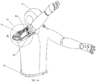
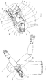
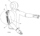
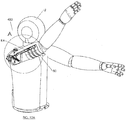
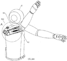
- FIGS. 1A-3B show a first example not belonging to the invention of an adaptive arm support system 10 worn by a user U.
- the system 10 (similar to the other systems herein) includes a harness 12 and an arm support mechanism 14 for supporting one or both of the user's arms (only one arm support 14 shown supporting the user's right arm RA for simplicity).
- the harness 12 may include one or more of an attachment band configured to be worn around the user's torso, e.g., chest, waist, and/or hips, a shoulder harness configured to be worn over and/or around the user's shoulders, and/or one or more vertical supports, e.g., extending between the attachment band and the shoulder harness (all not shown for clarity), e.g., similar to the support systems disclosed in U.S. Publication Nos. 2012/ 0184880 , 2014/ 0033391 , and 2014/ 0158839 , and in International Publication No. WO 2015/2015/ 157473 .
- the harness 12 may include a shoulder bracket and/or frame with a fixed end disposed above or adjacent to the user's shoulder to which other components of the system 10 may be coupled, e.g., to provide the arm support 14, which pivots about one or more axes relative to the shoulder bracket, similar to the systems in these publications.
- the systems herein may also include additional components similar to those disclosed in these publications, such as armrest 80, as desired.
- FIGS. 1A and 2A show perspective views of the adaptive arm support system 10, acting to provide a lift force on the user U's right arm RA through armrest 80.
- the arm support system 10 and the right arm RA are shown raised in FIG. 1A and lowered in FIG. 2A .
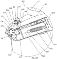
- the arm support mechanism 14 includes a first support segment, member, or shoulder bar 22 pivotally coupled to the harness 12, e.g., to the fixed shoulder bracket (not shown) on the harness 12, such that the shoulder bar 22 rotates horizontally about a vertical pivot 20, and a second support segment, member, bar, or chassis 30 pivotally coupled to the shoulder bar 22 such that the chassis 30 rotates vertically about a horizontal pivot 28.
- the shoulder vertical pivot 20 may permit rotation of the arm support 14 about a substantially vertical axis.
- the shoulder bar 22 connects shoulder vertical pivot 20 to a hub 26, which is fixedly mounted to the shoulder bar 22 and includes shoulder horizontal pivot 28, enabling rotation of the chassis 30 about a substantially horizontal axis.
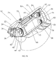
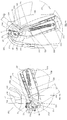
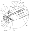
- the chassis 30 provides a mounting structure for several components, e.g., contained within a housing or cartridge (not shown to facilitate identification of the internal components).
- the chassis 30 may include one or more compensation elements, e.g., springs, pulleys, cables, and the like, that apply an offset force to at least partially offset a gravitational force acting on the arm RA as the user moves, e.g., providing a variable offset force based on the orientation of the arm RA.
- the chassis 30 may include a first pulley 40 and a second pulley 42 mounted thereto, which are joined together and move as one, e.g., rotating about axle 44.
- a first tension element e.g., first cable, 62
- a first end of leaf spring 70 is attached to the chassis 30 at cantilever fitting 74.
- the second, free end of the leaf spring 70 is attached to a pulley hub 72, which includes moving axle 54 about which zero, one, or more moving pulleys 50 rotate.
- Pulleys 50 may include tension element track or groove 52 (best seen in FIG. IB).
- One or more stationary pulleys 56 may rotate about stationary axle 58, and may include a tension element track or groove 53. Together moving pulley(s) 50 and stationary pulley(s) 56 form a "block and tackle" mechanism by which force in a second tension element, e.g., second cable 66, may be amplified by multiplying the number of wraps of the second tension element 66 within the "block and tackle," and thus effectively increasing the number of tension elements working to deflect the leaf spring 70.
- the first end of second tension element 66 is attached to second pulley 42, and wraps about one or more of the moving pulley(s) 50 and stationary pulley(s) 56 (within tension element grooves 52 and 53 respectively).
- the second end of the second tension element 66 may be attached at one of various points, e.g., to the stationary axle 58 or to the moving axle 54.
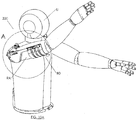
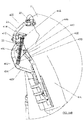
- FIGS. 2B and 3B are details showing the arm RA and arm support 14 being lowered, as shown in FIG. 2A .
- the first tension element 62 unwraps from the first pulley 40, and both the first pulley 40 and the second pulley 42 have, in response, rotated (together) about the axle 44.
- the second tension element 66 is wrapped farther onto the second pulley 42. This, in turn, tightens the wraps of the second tension element 66 within the "block and tackle,” drawing the moving pulley(s) 50 closer to the stationary pulley(s) 56, and deflecting the leaf spring 70 in response.
- the distance that the moving pulley(s) 50 draw closer to the stationary pulley(s) 56 are a function of the mechanical advantage provided by the number of effective wraps of the second tension element 66. For example, if there are five (5) effective wraps of the second tension element 66 within the "block and tackle," the moving pulley(s) 50 will draw closer to the stationary pulley(s) 56 approximately one fifth (1/5) of the change in length of the second tension element 66 (as it is wrapped around the second pulley 42).
- FIGS. 1B and 3A the user U's right arm RA is shown raised, and the leaf spring 70 is relatively un-deflected, and the moving pulley(s) 50 are separated from the stationary pulley(s) 56. In this position, the leaf spring 70 provides a lift force on the right arm RA, which is a function of the geometry of the components of the compensation elements, including the radii and sizes of the first pulley 40 and the second pulley 42.
- FIG. 3B the user U's right arm RA is shown lowered, approximately along arc A1.
- the leaf spring 70 is relatively deflected, having been pulled toward the stationary pulley(s) 56, and the moving pulley(s) 50 are closer to the stationary pulley(s) 56.
- the leaf spring 70 substantially deflected in response to the motion of the right arm RA, approximately along path P1, is necessarily imparting greater force to the second tension element 66.
- the greater force in the second tension element 66 is unable to create a greater lift force on the right arm RA because of the geometry of the components, including the radii and sizes of the first pulley 40 and the second pulley 42, which act to negate the increased force of the leaf spring 70 and thus moderate the lift force on the right arm RA, e.g., by "disadvantaging the spring," similar to the examples in the published applications referred to previously. It will be appreciated that the geometry of the components may be changed, as desired, to achieve the desired force modification applied to the right arm RA during movement of the arm RA through its normal range of motion.
- the leaf spring 70 may be constructed of various metals (e.g., steel), polymers (e.g., Polyacetal), elastomers (e.g., Polyurethane), composites (e.g., carbon fiber structures), and/or natural materials (e.g., wood or bamboo).
- metals e.g., steel
- polymers e.g., Polyacetal
- elastomers e.g., Polyurethane
- composites e.g., carbon fiber structures
- natural materials e.g., wood or bamboo
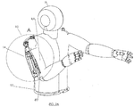
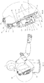
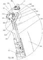
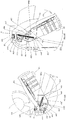
- FIGS. 4A-6B another example not belonging to the invention of an adaptive arm support system 100 is shown, which includes a harness and arm support, generally similar to other embodiments described with reference to the arm support system 10 of FIGS. 1A-3B and/or as described in the published applications referred to previously.
- the arm support system 100 differs from the arm support system 10 only in that the leaf spring 110 is deflected in direction substantially perpendicular to the direction of deflection of the leaf spring 70 shown in FIGS. 1A-3B .
- FIG. 4A shows the system 100 with the right arm RA and the arm support raised
- FIG. 5A shows the right arm RA lowered
- FIGS. 4B and 6A are details with the arm support raised as in FIG. 4A
- FIGS. 5B and 6B are details with the arm support lowered as in FIG. 5A and provide additional details of a chassis 105 carrying a plurality of components of the compensation elements of the arm support.
- the chassis 105 which rotates about shoulder horizontal pivot 28, provides a mounting structure for several components, as did chassis 30 from FIG. 1A-3B , e.g., including a first pulley 40 and a second pulley 42, which are joined together and rotate as one about axle 44.
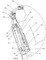
- a first tension element or cable 62 is attached to the first pulley 40 and to an anchor point 24 on hub 26.
- the first end of the leaf spring 110 is attached to the chassis 105 at cantilever fitting 112.
- the second, free end of the leaf spring 110 is attached to pulley hub 130, which includes moving axle 121 about which zero, one, or more moving pulleys 120 rotate.
- One or more stationary pulleys 115 are mounted to the chassis 105 adjacent the moving pulley(s) 120, which are free to rotate about stationary axle 116.
- the moving pulley(s) 120 and stationary pulley(s) 115 form a "block and tackle" by which force in a second tension element or cable 124 may be amplified by multiplying the number of wraps of the second tension element 124 within the "block and tackle," and thus effectively increasing the number of tension elements working to deflect the leaf spring 110.
- the first end of the second tension element 124 is attached to the second pulley 42 and wraps about one or more of the moving pulley(s) 120 and stationary pulley(s) 115.
- the second end of the second tension element 124 may be attached at one of several points, e.g., to the stationary axle 116 or to the moving axle 121. As described previously with reference to FIG.
- FIGS. 5B and 6B are detail of the chassis 105 as shown in FIG. 5A .
- the first tension element 62 unwraps from the first pulley 40 and, in response, both the first pulley 40 and the second pulley 42 rotate together about the axle 44.
- the second tension element 124 is wrapped farther onto the second pulley 42. This, in turn, tightens the wraps of the second tension element 124 within the "block and tackle,” drawing the moving pulley(s) 120 closer to the stationary pulley(s) 115, and deflecting the leaf spring 110 in response.
- the distance that the moving pulley(s) 120 draws closer to the stationary pulley(s) 115 is a function of the mechanical advantage provided by the number of effective wraps of second tension element 124. For example, if there are five (5) effective wraps of the second tension element 124 within the "block and tackle," the moving pulley(s) 120 may draw closer to the stationary pulley(s) 115 approximately one fifth (1/5) of the change in length of the second tension element 66 (as it is wrapped around the second pulley 42).
- the right arm RA is raised, and the leaf spring 110 is relatively un-deflected, and the moving pulley(s) 120 are separated from the stationary pulley(s) 115.
- the leaf spring 110 provides a lift force on the right arm RA, which is a function of the geometry of the components, including the radii and sizes of the first pulley 40 and the second pulley 42.
- the right arm RA is shown lowered approximately along arc A2.
- the leaf spring 110 is relatively deflected, having been pulled toward the stationary pulley(s) 115, and the moving pulley(s) 120 are closer to the stationary pulley(s) 115.
- the leaf spring 110 substantially deflected in response to the motion of the right arm RA, approximately along path P2, imparts greater force to the second tension element 124.
- the greater force in the second tension element 124 is unable to create a greater lift force on the right arm RA because of the geometry of the system components, including the radii and sizes of the first pulley 40 and the second pulley 42, which act to negate the increased force of the spring 110, by "disadvantaging the spring," and thus moderate the lift force on the right arm RA. It will be appreciated that the geometry of the components may be changed, as desired, to achieve the desired force modification applied to the right arm RA during movement of the arm RA through its normal range of motion.
- the leaf spring 110 may be constructed using various materials and/or methods, e.g., one or more metals (e.g., steel), polymers (e.g., Polyacetal), elastomers (e.g., Polyurethane), composites (e.g., Carbon fiber structures), and/or natural materials (e.g., wood or bamboo).
- metals e.g., steel
- polymers e.g., Polyacetal
- elastomers e.g., Polyurethane
- composites e.g., Carbon fiber structures
- natural materials e.g., wood or bamboo
- FIGS. 7A-9B an embodiment of an adaptive arm support system 200 is shown that also includes a harness and an arm support supporting one or both of the user's arms (only the right arm RA shown), generally similar to other embodiments described herein and in the published applications referred to previously.
- the harness and shoulder bracket are not shown for clarity.
- FIG. 7A shows a perspective view of the arm support system 200, with the right arm RA raised, and the arm support acting to provide a lift force on the right arm RA through an armrest 80, while FIG. 8A shows the right arm RA lowered.
- the arm support system 200 includes a single symmetrical, e.g., circular, pulley 230, that rotates about a moving axle 234 that changes in position, thereby changing the location of the symmetrical pulley 230 and providing a variable offset force between the shoulder bar 22 and the chassis or cartridge 210.
- a single symmetrical, e.g., circular, pulley 230 that rotates about a moving axle 234 that changes in position, thereby changing the location of the symmetrical pulley 230 and providing a variable offset force between the shoulder bar 22 and the chassis or cartridge 210.
- FIGS. 7B and 9A are details of the chassis 210 with the right arm RA raised
- FIGS. 8B and 9B are details of the chassis 210 with the right arm RA lowered, thereby showing the changing configuration of the compensation elements as the right arm RA is raised and lowered.
- a shoulder vertical pivot 20 may permit rotation of the arm support of the arm support system 200 about a substantially vertical axis.
- the shoulder bar 22 connects the shoulder vertical pivot 20 to a hub 214, which includes shoulder horizontal pivot 28, enabling rotation about a substantially horizontal axis, similar to other embodiments herein.
- the chassis 210 rotates about the shoulder horizontal pivot 28, and provides a mounting structure for several components of the compensation element. For example, a first end of a spring or other resilient element 220 connects to the chassis 210, via attachment element 222, at post 224. The second end of the resilient element 220 connects to a tension element or cable 240 via a hook or other attachment element 226.
- the tension element 240 wraps around the pulley 230 and is attached to the hub 214 at anchor point 244.
- the pulley 230 rotates about the moving axle 234, which may translate along a slot 212 in the chassis 210, thereby changing the position of the pulley 230 and the distance between the pulley 230 and the shoulder horizontal pivot 28.
- a cam plate 250 is fixedly connected to the hub 214 (and consequently to the shoulder bar 22), and includes a cam slot 254, within which the moving axle 234 may also translate. As explained below, the cam slot 254 determines the translation of the moving axle 234, and thus the pulley 230, within the slot 212 in the chassis 210. Thus, by changing the position of the pulley 230, the influence of the resilient element 220, and thus the lift force on the right arm RA, may be controlled. For example, if the resilient element 220 is relatively un-deflected (i.e., retracted) as shown in FIGS. 7B and 9A , it will have less ability to apply a lift force to the right arm RA.
- the right arm RA is raised, and the resilient element 220 is relatively un-deflected, and the pulley 230 (carried on the moving axle 234 guided by the cam slot 254, and which has translated within the slot 212 in the chassis 210) is displaced from the shoulder horizontal pivot 28 by distance D1.
- the cam slot 254 may be configured to modify the position of the pulley 230 relative to the shoulder horizontal pivot 27, as desired.
- the cam slot 254 may be shaped to maximize the distance of the pulley 230 from the shoulder horizontal pivot 28 when the right arm RA is raised and the resilient element 220 is applying relatively little force (thereby increasing the net lift force acting on the right arm RA), and to minimize the distance of the pulley 230 from the shoulder horizontal pivot 28 when the right arm RA is lowered and the resilient element 220 is applying greater force (thereby decreasing the net lift force acting on the right arm RA).
- the shape of the cam slot 254 may create various lift force profiles.
- An example of a desirable lift profile may be to maximize the lift force when the right arm RA is raised, consistent with working overhead, and to have the lift force reduced to a low level when the right arm RA is lowered, consistent with resting with the right arm RA by the user's side.
- the cam slot 254 may be configured to apply a consistent lift force through a specific range of arm position, but to apply no lift above or below that range. Many lift profiles may be achieved by varying the shape of the cam slot 254.
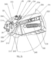
- FIGS. 10A-12B another exemplary embodiment of an adaptive arm support system 300 is shown that generally includes a harness worn by a user U and one or two arm supports (one shown supporting a right arm RA of the user U), e.g., including a shoulder bracket 22 and chassis 320 carrying one or more compensation elements, similar to other embodiments herein.
- FIG. 10A shows a perspective view of the arm support system 300, acting to provide a lift force on the right arm RA through an armrest 80 with the right arm RA shown raised, while FIG. 11A shows the right arm RA lowered.
- a shoulder vertical pivot 20 may permit rotation of the shoulder bracket 22 of the arm support system 300 about a substantially vertical axis.
- the shoulder bar 22 connects the shoulder vertical pivot 20 to a hub 310, which includes a shoulder horizontal pivot 28, enabling rotation of the chassis 320 about a substantially horizontal axis, while a resilient torsion element 350 acts to provide a lift force on the right arm RA.
- a cam plate 340 is rigidly attached to the hub 310 that includes a cam slot 342 defining a desired curvilinear path for a moving axle 356 to modify the force applied by the torsion element 350 on the right arm RA, as explained further below.
- the chassis 320 and cover 330 also include one or more slots, e.g., including outer slot 334 and inner slot 322 (shown in 11B) within which the moving axle 356 also translates, e.g., in combination with the cam slot 342 in the cam plate 340 to vary the position of the moving axle 356 as the right arm RA is raised and lowered, as described below.
- slots e.g., including outer slot 334 and inner slot 322 (shown in 11B) within which the moving axle 356 also translates, e.g., in combination with the cam slot 342 in the cam plate 340 to vary the position of the moving axle 356 as the right arm RA is raised and lowered, as described below.
- FIGS. 10B and 11B are details corresponding to FIGS. 10A and 11A , respectively, and FIGS. 12A and 12B show side views of FIGS. 10B and 11B , respectively, with a cover 330 of the chassis 320 removed to show components of the compensation elements.
- the resilient torsion element 350 is a torsion spring with legs 352, 354.
- other resilient elements may be provided, e.g., an extension spring, as shown in FIGS. 13A-15B .
- FIGS. 13A-15B As best seen in FIGS.
- a first or moving leg 352 of the spring 350 is constrained by and/or coupled to a roller 360 on the moving axle 356 and a second or stationary leg 354 of the spring 350 is constrained by and/or coupled to the hub 28.
- FIGS. 11A-12B Operation of the arm support system 300 is shown in FIGS. 11A-12B .
- the moving axle 356, guided by the cam slot 344 has translated within the slots 322 and 334 in the chassis 320 and cover 330, carrying with it a roller 360.
- the position of the roller 360, closer to the shoulder horizontal pivot 28 (as contrasted with the position of the roller 360 in FIGS. 10B and 12A ), results in a shorter moment arm (lever) over which the resilient torsion element 350 (which is now deflected, and therefore applying a higher force to the roller 360), can act on the right arm RA (thereby "disadvantaging the spring").
- FIGS. 10B and 12A the right arm RA is shown raised, the resilient torsion element 350 is relatively un-deflected, and the roller 360 (carried on the moving axle 356 and therefore guided by the cam slot 344 and translating along the slot 322, 334) is displaced from the shoulder horizontal pivot 28 by distance D6.
- the roller 360 is in contact with the moving leg 352 of the resilient torsion element 350 at distance D5 from the center 312 of the torsion element 350.
- the stationary leg 354 of the torsion element 350 is in stationary contact with the hub 310.
- the right arm RA is lowered (approximately along arc A4).
- the resilient torsion element 350 is more deflected (in contrast to the deflection at the raised position of FIG. 12A ).
- the moving axle 356 has travelled within the cam slot 344 approximately along path P5, and has simultaneously translated within the slots 322, 334 in the chassis 320 and cover 330 under the guidance of the cam slot 344, approximately along path P6.
- the roller 360, carried on the moving axle 356, is displaced from the shoulder horizontal pivot 28 by distance D8, and is in contact with the moving leg 352 of the torsion element 350 at distance D7 from the center 312 of the torsion element 350.
- the roller 360 Because distance D7 is greater than distance D5, the roller 360 has a greater mechanical advantage on the torsion element 350 in the lowered position than it does in the raised position. Because distance D6 is greater than distance D8, the roller 360 has a lower mechanical advantage on the chassis 320 in the lowered position than it does in the raised position. The combination of greater mechanical advantage of the roller 360 over the torsion element 350 and lower mechanical advantage of the roller 360 on the chassis 320 has the result that the increased torsional force in the torsion element 350 (in the lowered position) is unable to increase the lift force on the right arm RA.
- the size and/or shape of the cam slot 344 may be configured, as desired, to modify the position of the roller 360 as it travels along the cam slot 344 to provide a desired lift force profile.
- the cam slot 344 may be shaped to maximize the distance of the roller 360 from the shoulder horizontal pivot 28 when the right arm RA is raised (e.g., as in FIG. 10A ) and the torsion element 350 is applying relatively little force, and to minimize the distance of the roller 360 from the shoulder horizontal pivot 28 when the right arm RA is lowered (e.g., as in FIG. 11A ) and the torsion element 350 is applying greater force.
- An example of a desirable lift profile might be to maximize the lift force when the right arm RA is raised, consistent with working overhead, or fully extended horizontally, and to have the lift force reduced to a relatively low level when the right arm RA is lowered, consistent with resting with the right arm RA by the user's side.
- the cam slot 344 can be configured to apply a consistent lift force through a specific range of arm position, but to apply no lift above or below that range. Many lift profiles can be achieved by varying the shape of the cam slot 344.
- the system 300 may be simplified, e.g., by making the roller 356 stationary at a predetermined location on the chassis 320 and omitting the cam plate 340.
- the distance of the roller 356 from the pivot 28 would change as the chassis 320 is raised and lowered, thereby moderating the lift force applied to the right arm RA, e.g., reducing the lift force as the right arm RA is lowered.
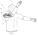
- FIGS. 13A-15B yet another exemplary embodiment of an adaptive arm support system 400 is shown.
- FIG. 13A shows a perspective view of the arm support system 400, acting to provide a lift force on the right arm RA of a user U through an armrest 80, with the arm support and the right arm RA raised, while FIG. 14A shows the arm support system 400 and the right arm RA lowered.
- the system 400 includes a harness (not shown) worn by a user U and an arm support supporting a right arm RA of the user U that includes a shoulder bracket 22 pivotally coupled to the harness, and a chassis 320 pivotally coupled to the shoulder bracket 22 and carrying one or more compensation elements, similar to other embodiments herein.
- FIGS. 13B , 14B , 15A, and 15B are details showing components of the compensation elements carried by the chassis 420 (with a cover, not shown, removed), e.g., a spring or other resilient member 460, a curvilinear shaped track 430, and a carriage 440 configured to travel on the track 430.
- a shoulder vertical pivot 20 may permit rotation of the arm support system 400 about a substantially vertical axis
- shoulder bar 22 connects the shoulder vertical pivot 20 to a hub 410, which includes a shoulder horizontal pivot 28, enabling rotation about a substantially horizontal axis.
- the chassis 420 rotates about the shoulder horizontal pivot 28 and provides a mounting structure for a shaped track 430, which rotates with the chassis 420 about the shoulder horizontal pivot 28).
- the carriage 440 provides mounting for multiple rollers 446, which follow the shaped track 430, permitting the carriage 440 to translate along the shaped track 430 as desired.
- the carriage 440 includes one or more mounting features for one end of the resilient element 460, e.g., a mount arm 450 and a mount tab 454.
- the mount tab 454 provides an attachment point for a first end of the resilient element 460, e.g., by coupling a hook or other attachment element 462 to the mount tab 454.
- a second end of the resilient element 460 is coupled to the hub 410, e.g., by coupling a hook or other attachment element 468 to attachment point 414 on the hub 410.
- FIGS. 13B and 14B are details corresponding to FIGS. 13A and 14A , respectively, and FIGS. 15A and 15B show side views of FIGS. 13B and 14B , respectively.
- the arm support and right arm RA of the user U are shown raised and the carriage 440 is located towards an outer end 430a of the shaped track 430.
- FIG. 15A shows the resilient element 460 relatively un-extended, and thus applying a relatively low force on the carriage 440.
- the carriage 440 is located towards the outer end 430a of the track 430 such that the resilient element 460 is acting at distance D9 from the shoulder horizontal pivot 28, and thus the resilient element 460 can provide an adequate lift force on the right arm RA.
- FIG. 15B shows user U's right arm RA lowered approximately along arc A5.
- Resilient element 460 is relatively extended, and thus applying a relatively large force on the carriage 440.
- the carriage 440 has simultaneously travelled along the shaped track 430, approximately along arc A6, moving closer to the inner end 430b of the track 430 and therefore closer the shoulder horizontal pivot 28.
- the resilient element 460 has extended, and, acting at distance D10 from shoulder horizontal pivot 28, is exerting more force on the mount tab 454 and attachment point 414 on the hub 410.
- the extended resilient element 460 is acting with less mechanical advantage, and thus does not provide an excessive lift force on the right arm RA (again thereby "disadvantaging the spring").
- the shape and/or position of the shaped track 430 may be modified, as desired, to provide a desired profile of lift forces on the right arm RA as it moves up and down, similar to the cam slot 344 described previously.
- FIGS. 16A-18B still another exemplary embodiment of an adaptive arm support system 500 is shown acting to provide a lift force on a right arm RA of a user U through an armrest 80 as the right arm RA is raised and lowered.
- the arm support system 500 and the right arm RA are shown raised, while in FIG. 17A , the arm support system and right arm RA are shown lowered.
- the system 500 includes a harness (not shown) worn by a user U and an arm support supporting one or both arms of the user U, which includes a shoulder bracket 22 pivotally coupled to the harness, and a chassis 510 pivotally coupled to the shoulder bracket 22 and carrying one or more compensation elements, similar to other embodiments herein.
- the arm support 500 employs a pair of symmetrical, e.g., circular, pulleys 530, 536, a curvilinear shaped track 544, and a carriage 548 to change the location of the attachment point of a tension element such as a cable 566, to moderate the lift force on the right arm RA.
- a tension element such as a cable 566
- Other previously disclosed components such as a frame, shoulder-centered gimbal, and harness are not shown for clarity.
- a shoulder vertical pivot 20 may permit rotation of the arm support system 500 about a substantially vertical axis
- shoulder bar 22 connects the shoulder vertical pivot 20 to a hub 520, which includes a shoulder horizontal pivot 28, enabling rotation about a substantially horizontal axis.
- the chassis 510 which rotates about shoulder horizontal pivot 28, provides a mounting structure for several components.
- an extension spring or other resilient element 560 may be coupled between the chassis 510 and the hub 520 to apply a desired lift force on the right RA.
- a first end of the resilient element 560 is connected to the chassis 510, e.g., via a hook or other attachment element 562, at post 514.
- a second end of the resilient element 560 connects to a tension element 644, e.g., via a hook or other attachment element 564.
- the chassis 510 which rotates about shoulder horizontal pivot 28, provides a mounting structure for the shaped track 544 (which rotates with it about shoulder horizontal pivot 28).
- the carriage 548 provides a mounting structure for multiple rollers 550, which follow the shaped track 544, permitting the carriage 548 to translate along the shaped track 544 as desired.
- a first pulley 530 is mounted within the hub 520, approximately concentric with the shoulder horizontal pivot 28, and a second pulley 536 is mounted within the hub 520 at axle 538.
- the tension element 560 wraps at least partially around the first pulley 538, the second pulley 536 and is attached to the carriage 548 at anchor point 552.
- FIG. 18A shows the resilient element 560 relatively un-extended, and thus applying a relatively low force on the tension element 566 and thus on the attachment point 538 of the carriage 548.
- the carriage 548 is located towards an outer end 544a of the shaped track 544 such that the resilient element 566 is acting at distance D11 from the shoulder horizontal pivot 28, and thus the resilient element 566 can provide an adequate lift force on the right arm RA.
- FIGS. 17B and 18B in response to the user U lowering right arm RA, the carriage 548 has travelled along the shaped track 544, moving closer to the shoulder horizontal pivot 28, while simultaneously the resilient element 560 has extended, and is exerting more force on the tension element 560.
- FIG. 18B shows user the right arm RA lowered approximately along arc A7.
- the resilient element 566 is relatively extended, and thus applying a relatively large force on the tension element 566 and thus on the attachment point 538 of the carriage 548.
- the carriage 548 has simultaneously travelled along the shaped track 544, approximately along arc A8, towards an inner end 544b of the shaped track 544, and the resilient element 566 is acting at distance D12 from the shoulder horizontal pivot 28.
- the extended resilient element 566 is acting with less mechanical advantage, and thus does not provide an excessive lift force on the right arm RA (again thereby "disadvantaging the spring").
- the shape and/or position of the shaped track 430 can be modified, as desired, to achieve the desired profile of lift forces on the right arm RA.
Landscapes
- Engineering & Computer Science (AREA)
- Health & Medical Sciences (AREA)
- Mechanical Engineering (AREA)
- Robotics (AREA)
- Biomedical Technology (AREA)
- Heart & Thoracic Surgery (AREA)
- Vascular Medicine (AREA)
- Life Sciences & Earth Sciences (AREA)
- Animal Behavior & Ethology (AREA)
- General Health & Medical Sciences (AREA)
- Public Health (AREA)
- Veterinary Medicine (AREA)
- Orthopedic Medicine & Surgery (AREA)
- Nursing (AREA)
- Manipulator (AREA)
- Rehabilitation Tools (AREA)
Applications Claiming Priority (2)
| Application Number | Priority Date | Filing Date | Title |
|---|---|---|---|
| US201462068547P | 2014-10-24 | 2014-10-24 | |
| PCT/US2015/057263 WO2016065350A1 (en) | 2014-10-24 | 2015-10-24 | Arm support systems |
Publications (3)
| Publication Number | Publication Date |
|---|---|
| EP3209467A1 EP3209467A1 (en) | 2017-08-30 |
| EP3209467A4 EP3209467A4 (en) | 2018-07-25 |
| EP3209467B1 true EP3209467B1 (en) | 2021-11-24 |
Family
ID=55761680
Family Applications (1)
| Application Number | Title | Priority Date | Filing Date |
|---|---|---|---|
| EP15853608.6A Not-in-force EP3209467B1 (en) | 2014-10-24 | 2015-10-24 | Arm support systems |
Country Status (4)
| Country | Link |
|---|---|
| US (1) | US10617551B2 (enExample) |
| EP (1) | EP3209467B1 (enExample) |
| JP (1) | JP6709214B2 (enExample) |
| WO (1) | WO2016065350A1 (enExample) |
Families Citing this family (38)
| Publication number | Priority date | Publication date | Assignee | Title |
|---|---|---|---|---|
| ITFI20120129A1 (it) | 2012-06-21 | 2013-12-22 | Scuola Superiore Di Studi Universit Ari E Di Perfe | Ausilio tecnologico per amputati transfemorali |
| ITFI20130156A1 (it) | 2013-07-01 | 2015-01-02 | Scuola Superiore Sant Anna | Molla torsionale |
| BR112017014169A2 (pt) | 2015-02-09 | 2018-01-09 | Scuola Superiore Di Studi Universitari E Di Perfezionamento Sant´Anna | sistema de acionamento para órtese de quadril |
| ITPI20150027A1 (it) | 2015-04-11 | 2016-10-11 | Azienda Ospedaliera Pisana | Sistema esoscheletrico ad alta ergonomia per l'arto superiore |
| DE102016104879B4 (de) * | 2016-03-16 | 2024-12-12 | Ottobock Se & Co. Kgaa | Orthese |
| DE102016121201B4 (de) * | 2016-11-07 | 2025-09-04 | Ottobock Se & Co. Kgaa | Orthese |
| CN110167726B (zh) * | 2016-10-21 | 2022-09-30 | 外骨骼控股有限公司 | 力平衡支撑件、机械设备和可穿戴支撑装置 |
| DE102016123797A1 (de) * | 2016-12-08 | 2018-06-14 | Bayerische Motoren Werke Aktiengesellschaft | Exoskelett |
| AU2017375795A1 (en) * | 2016-12-13 | 2019-07-11 | Abilitech Medical, Inc. | Upper torso augmentation system and method |
| EP3624996A4 (en) * | 2017-05-15 | 2021-03-24 | Enhance Technologies, LLC | ARM SUPPORT SYSTEMS |
| DE102017112436B4 (de) | 2017-06-06 | 2019-05-29 | Ottobock Se & Co. Kgaa | Vorrichtung zum Unterstützen wenigstens eines Armes eines Benutzers |
| US11787068B2 (en) * | 2017-06-29 | 2023-10-17 | Sony Interactive Entertainment Inc. | Robot joint structure |
| IT201700081177A1 (it) * | 2017-07-18 | 2019-01-18 | Iuvo S R L | "Sistema di assistenza agli sforzi da parte di un operatore" |
| US12440303B2 (en) | 2017-08-11 | 2025-10-14 | Roger J. Malcolm | Body worn body part support device and method |
| GB2567010A (en) * | 2017-10-02 | 2019-04-03 | Univ Strathclyde | Apparatus for the rehabilitation, assistance and/or augmentation of arm strength in a user |
| CN107932478B (zh) * | 2017-11-15 | 2019-10-08 | 北京林业大学 | 一种上肢采摘辅助外骨骼 |
| US10741055B2 (en) | 2018-01-01 | 2020-08-11 | Bi Incorporated | Systems and methods for hybrid non-exclusion zone violating route determination |
| DE102018108416A1 (de) * | 2018-04-10 | 2019-10-10 | Ottobock Se & Co. Kgaa | Vorrichtung zum Unterstützen wenigstens eines Armes |
| WO2019219833A1 (fr) * | 2018-05-18 | 2019-11-21 | Ergosante Technologie | Bras mecanique adapte a supporter un bras d'un operateur |
| FR3081116B1 (fr) * | 2018-05-18 | 2020-07-03 | Ergosante Technologie | Bras mecanique adapte a supporter un bras d'un operateur |
| FR3085292B1 (fr) * | 2018-08-29 | 2020-11-27 | Human Mechanical Tech | Exosquelette adapte a generer un effort de compensation d’intensite variable en fonction de la position d’un membre superieur d’un utilisateur |
| JP2020059092A (ja) * | 2018-10-10 | 2020-04-16 | トヨフレックス株式会社 | 動作補助装置 |
| DE102018127553B4 (de) * | 2018-11-05 | 2020-11-05 | Ottobock Se & Co. Kgaa | Vorrichtung zum Unterstützen wenigstens eines Armes eines Benutzers |
| KR102603041B1 (ko) * | 2018-12-12 | 2023-11-16 | 현대자동차주식회사 | 착용식 근력 보조 장치 |
| KR102660352B1 (ko) * | 2019-02-19 | 2024-04-24 | 현대자동차주식회사 | 착용식 근력 보조 장치 |
| CN113853182A (zh) | 2019-04-10 | 2021-12-28 | 艾比力泰克医疗公司 | 具有动态调平系统的上躯干可穿戴矫形装置 |
| US10893383B2 (en) | 2019-05-06 | 2021-01-12 | Bi Incorporated | Systems and methods for monitoring system equipment diagnosis |
| CN110327181B (zh) * | 2019-07-08 | 2022-05-13 | 湖北英特搏智能机器有限公司 | 一种上肢外骨骼康复机器人的臂长调节装置及张紧机构 |
| FR3105056B1 (fr) * | 2019-12-20 | 2023-09-08 | Commissariat Energie Atomique | Equilibreur de charge passif |
| CN111000699B (zh) * | 2019-12-26 | 2022-03-04 | 中国科学院宁波工业技术研究院慈溪生物医学工程研究所 | 一种刚柔混合式上肢辅助运动装置 |
| CN111671617B (zh) * | 2020-06-16 | 2023-12-05 | 湖北英特搏智能机器有限公司 | 一种维持绳索张力恒定的绳驱外骨骼机械臂长度调节连杆 |
| KR102265666B1 (ko) * | 2020-10-27 | 2021-06-16 | 금오공과대학교 산학협력단 | 하지 외골격 로봇의 근력 보조장치 |
| KR102948432B1 (ko) | 2020-11-20 | 2026-04-06 | 현대자동차주식회사 | 근력 보조 장치 |
| JP2022104462A (ja) * | 2020-12-28 | 2022-07-08 | 株式会社イノフィス | 腕部補助装置 |
| JP2024540727A (ja) * | 2021-11-03 | 2024-11-01 | レヴィテイト テクノロジーズ,インコーポレイテッド | アームサポートシステムおよびその使用方法 |
| WO2023091099A1 (en) * | 2021-11-18 | 2023-05-25 | Ocali̇s Mühendi̇sli̇k Anoni̇m Şi̇rketi̇ | Wearable arm support system |
| JP2023159829A (ja) * | 2022-04-20 | 2023-11-01 | フリー バイオニクス タイワン インコーポレイテッド | 外骨格型ロボットアームアセンブリ |
| US12588778B2 (en) * | 2024-05-01 | 2026-03-31 | Sergio Castaneda | Uplifted hands assist device for praying like moses |
Family Cites Families (20)
| Publication number | Priority date | Publication date | Assignee | Title |
|---|---|---|---|---|
| US2310566A (en) * | 1939-02-07 | 1943-02-09 | Anderson Roger | Clavicle splint |
| US2535489A (en) * | 1947-03-05 | 1950-12-26 | Harold T Edwards | Artificial arm |
| DE2615209A1 (de) * | 1975-04-15 | 1976-10-28 | Teufel Wilh Jul Fa | Universal-orthese |
| DE3345386A1 (de) * | 1983-12-15 | 1985-06-27 | Ernst Knoll Feinmechanik, 7801 Umkirch | Einrichtung zum abstuetzen eines armes |
| DE4324399C1 (de) * | 1993-07-21 | 1995-02-09 | Bock Orthopaed Ind | Ellbogenlifter |
| US6113562A (en) * | 1998-06-01 | 2000-09-05 | Peter M. Bonutti | Shoulder orthosis |
| US7410472B2 (en) * | 2005-02-22 | 2008-08-12 | Ottawa Health Research Institute | Articulating joint |
| GB2455427B (en) * | 2005-10-11 | 2009-12-02 | Panasonic Corp | Motion Assistance Apparatus |
| FR2917323B1 (fr) * | 2007-06-12 | 2009-10-02 | Commissariat Energie Atomique | Mecanisme de rotation d'avant-bras et orthese comportant un tel mecanisme |
| JP5173404B2 (ja) * | 2007-12-28 | 2013-04-03 | パナソニック株式会社 | 筋力補助装置及びその動作方法 |
| JP2011092507A (ja) * | 2009-10-30 | 2011-05-12 | Satsuma Tsushin Kogyo Kk | 装着型筋力補助装置 |
| US8591441B2 (en) * | 2010-10-22 | 2013-11-26 | Peter M. Bonutti | Shoulder orthosis including flexion/extension device |
| WO2012099995A2 (en) * | 2011-01-18 | 2012-07-26 | Doyle Mark C | Adaptive arm support systems and methods for use |
| JP5804310B2 (ja) * | 2011-05-24 | 2015-11-04 | 学校法人東京理科大学 | 上腕保持装置、及び、上腕補助装置 |
| US9999534B2 (en) * | 2012-07-31 | 2018-06-19 | Enhance Technologies, LLC | Adaptive arm support systems and methods for use |
| EP2931484B1 (en) * | 2012-12-11 | 2018-03-21 | Enhance Technologies, LLC | Adaptive arm support systems and methods for use |
| WO2014092162A1 (ja) * | 2012-12-14 | 2014-06-19 | 国立大学法人名古屋工業大学 | 歩行支援機 |
| US10667938B2 (en) * | 2015-10-07 | 2020-06-02 | Bonutti Research, Inc. | Orthosis for range of motion |
| TWI600421B (zh) * | 2016-01-05 | 2017-10-01 | 國立成功大學 | 肩關節復健輔具 |
| US20170203432A1 (en) * | 2016-01-16 | 2017-07-20 | Konstantinos Andrianesis | Actuation apparatus for wearable devices |
-
2015
- 2015-10-24 JP JP2017521574A patent/JP6709214B2/ja not_active Expired - Fee Related
- 2015-10-24 EP EP15853608.6A patent/EP3209467B1/en not_active Not-in-force
- 2015-10-24 WO PCT/US2015/057263 patent/WO2016065350A1/en not_active Ceased
-
2017
- 2017-04-24 US US15/494,966 patent/US10617551B2/en active Active
Also Published As
| Publication number | Publication date |
|---|---|
| WO2016065350A1 (en) | 2016-04-28 |
| US20170224517A1 (en) | 2017-08-10 |
| US10617551B2 (en) | 2020-04-14 |
| JP2017533833A (ja) | 2017-11-16 |
| JP6709214B2 (ja) | 2020-06-10 |
| EP3209467A1 (en) | 2017-08-30 |
| EP3209467A4 (en) | 2018-07-25 |
Similar Documents
| Publication | Publication Date | Title |
|---|---|---|
| EP3209467B1 (en) | Arm support systems | |
| US10816135B2 (en) | Heavy capacity arm support systems | |
| JP6515265B2 (ja) | 適応型アームサポートシステム及びその使用方法 | |
| US11253381B2 (en) | Head support systems and methods for use | |
| EP2185036B1 (en) | Articulated human arm support | |
| US20200188212A1 (en) | Wearable apparatus for increasing muscular force | |
| KR20200101572A (ko) | 착용식 근력 보조 장치 | |
| US20200146923A1 (en) | Arm support systems | |
| CN109058723A (zh) | 一种台式计算机用显示屏支撑装置 | |
| US12121462B2 (en) | Head support systems and methods for use | |
| CN103363269A (zh) | 移动式电脑显示器 | |
| EP4482655A1 (en) | Head support systems and methods for use | |
| KR102663601B1 (ko) | 착용식 근력 보조 장치의 상완 모듈 및 이를 포함한 착용식 근력 보조 장치 | |
| US20210154081A1 (en) | Wearable apparatus for assisting muscular strength | |
| US10925799B2 (en) | Suspension device for balancing a weight | |
| CN215577729U (zh) | 一种射线防护装置 | |
| CN117163869A (zh) | 一种恒力助力装置、升降机构及患者手术操作平台 | |
| CN113205898A (zh) | 一种射线防护装置 |
Legal Events
| Date | Code | Title | Description |
|---|---|---|---|
| STAA | Information on the status of an ep patent application or granted ep patent |
Free format text: STATUS: THE INTERNATIONAL PUBLICATION HAS BEEN MADE |
|
| PUAI | Public reference made under article 153(3) epc to a published international application that has entered the european phase |
Free format text: ORIGINAL CODE: 0009012 |
|
| STAA | Information on the status of an ep patent application or granted ep patent |
Free format text: STATUS: REQUEST FOR EXAMINATION WAS MADE |
|
| 17P | Request for examination filed |
Effective date: 20170519 |
|
| AK | Designated contracting states |
Kind code of ref document: A1 Designated state(s): AL AT BE BG CH CY CZ DE DK EE ES FI FR GB GR HR HU IE IS IT LI LT LU LV MC MK MT NL NO PL PT RO RS SE SI SK SM TR |
|
| AX | Request for extension of the european patent |
Extension state: BA ME |
|
| DAV | Request for validation of the european patent (deleted) | ||
| DAX | Request for extension of the european patent (deleted) | ||
| RAP1 | Party data changed (applicant data changed or rights of an application transferred) |
Owner name: ENHANCE TECHNOLOGIES, LLC |
|
| A4 | Supplementary search report drawn up and despatched |
Effective date: 20180622 |
|
| RIC1 | Information provided on ipc code assigned before grant |
Ipc: B25J 19/00 20060101ALI20180618BHEP Ipc: B25J 9/08 20060101AFI20180618BHEP Ipc: B25J 18/00 20060101ALI20180618BHEP Ipc: B25J 9/10 20060101ALI20180618BHEP Ipc: A61F 5/01 20060101ALN20180618BHEP Ipc: B25J 9/00 20060101ALI20180618BHEP |
|
| GRAP | Despatch of communication of intention to grant a patent |
Free format text: ORIGINAL CODE: EPIDOSNIGR1 |
|
| STAA | Information on the status of an ep patent application or granted ep patent |
Free format text: STATUS: GRANT OF PATENT IS INTENDED |
|
| RIC1 | Information provided on ipc code assigned before grant |
Ipc: A61F 5/01 20060101ALN20210429BHEP Ipc: B25J 19/00 20060101ALI20210429BHEP Ipc: B25J 9/00 20060101ALI20210429BHEP Ipc: B25J 18/00 20060101ALI20210429BHEP Ipc: B25J 9/10 20060101ALI20210429BHEP Ipc: B25J 9/08 20060101AFI20210429BHEP |
|
| INTG | Intention to grant announced |
Effective date: 20210520 |
|
| GRAS | Grant fee paid |
Free format text: ORIGINAL CODE: EPIDOSNIGR3 |
|
| GRAA | (expected) grant |
Free format text: ORIGINAL CODE: 0009210 |
|
| STAA | Information on the status of an ep patent application or granted ep patent |
Free format text: STATUS: THE PATENT HAS BEEN GRANTED |
|
| AK | Designated contracting states |
Kind code of ref document: B1 Designated state(s): AL AT BE BG CH CY CZ DE DK EE ES FI FR GB GR HR HU IE IS IT LI LT LU LV MC MK MT NL NO PL PT RO RS SE SI SK SM TR |
|
| REG | Reference to a national code |
Ref country code: GB Ref legal event code: FG4D |
|
| REG | Reference to a national code |
Ref country code: AT Ref legal event code: REF Ref document number: 1449502 Country of ref document: AT Kind code of ref document: T Effective date: 20211215 |
|
| REG | Reference to a national code |
Ref country code: DE Ref legal event code: R096 Ref document number: 602015075294 Country of ref document: DE |
|
| REG | Reference to a national code |
Ref country code: IE Ref legal event code: FG4D |
|
| REG | Reference to a national code |
Ref country code: LT Ref legal event code: MG9D |
|
| REG | Reference to a national code |
Ref country code: NL Ref legal event code: MP Effective date: 20211124 |
|
| REG | Reference to a national code |
Ref country code: AT Ref legal event code: MK05 Ref document number: 1449502 Country of ref document: AT Kind code of ref document: T Effective date: 20211124 |
|
| PG25 | Lapsed in a contracting state [announced via postgrant information from national office to epo] |
Ref country code: RS Free format text: LAPSE BECAUSE OF FAILURE TO SUBMIT A TRANSLATION OF THE DESCRIPTION OR TO PAY THE FEE WITHIN THE PRESCRIBED TIME-LIMIT Effective date: 20211124 Ref country code: LT Free format text: LAPSE BECAUSE OF FAILURE TO SUBMIT A TRANSLATION OF THE DESCRIPTION OR TO PAY THE FEE WITHIN THE PRESCRIBED TIME-LIMIT Effective date: 20211124 Ref country code: FI Free format text: LAPSE BECAUSE OF FAILURE TO SUBMIT A TRANSLATION OF THE DESCRIPTION OR TO PAY THE FEE WITHIN THE PRESCRIBED TIME-LIMIT Effective date: 20211124 Ref country code: BG Free format text: LAPSE BECAUSE OF FAILURE TO SUBMIT A TRANSLATION OF THE DESCRIPTION OR TO PAY THE FEE WITHIN THE PRESCRIBED TIME-LIMIT Effective date: 20220224 Ref country code: AT Free format text: LAPSE BECAUSE OF FAILURE TO SUBMIT A TRANSLATION OF THE DESCRIPTION OR TO PAY THE FEE WITHIN THE PRESCRIBED TIME-LIMIT Effective date: 20211124 |
|
| PG25 | Lapsed in a contracting state [announced via postgrant information from national office to epo] |
Ref country code: IS Free format text: LAPSE BECAUSE OF FAILURE TO SUBMIT A TRANSLATION OF THE DESCRIPTION OR TO PAY THE FEE WITHIN THE PRESCRIBED TIME-LIMIT Effective date: 20220324 Ref country code: SE Free format text: LAPSE BECAUSE OF FAILURE TO SUBMIT A TRANSLATION OF THE DESCRIPTION OR TO PAY THE FEE WITHIN THE PRESCRIBED TIME-LIMIT Effective date: 20211124 Ref country code: PT Free format text: LAPSE BECAUSE OF FAILURE TO SUBMIT A TRANSLATION OF THE DESCRIPTION OR TO PAY THE FEE WITHIN THE PRESCRIBED TIME-LIMIT Effective date: 20220324 Ref country code: PL Free format text: LAPSE BECAUSE OF FAILURE TO SUBMIT A TRANSLATION OF THE DESCRIPTION OR TO PAY THE FEE WITHIN THE PRESCRIBED TIME-LIMIT Effective date: 20211124 Ref country code: NO Free format text: LAPSE BECAUSE OF FAILURE TO SUBMIT A TRANSLATION OF THE DESCRIPTION OR TO PAY THE FEE WITHIN THE PRESCRIBED TIME-LIMIT Effective date: 20220224 Ref country code: NL Free format text: LAPSE BECAUSE OF FAILURE TO SUBMIT A TRANSLATION OF THE DESCRIPTION OR TO PAY THE FEE WITHIN THE PRESCRIBED TIME-LIMIT Effective date: 20211124 Ref country code: LV Free format text: LAPSE BECAUSE OF FAILURE TO SUBMIT A TRANSLATION OF THE DESCRIPTION OR TO PAY THE FEE WITHIN THE PRESCRIBED TIME-LIMIT Effective date: 20211124 Ref country code: HR Free format text: LAPSE BECAUSE OF FAILURE TO SUBMIT A TRANSLATION OF THE DESCRIPTION OR TO PAY THE FEE WITHIN THE PRESCRIBED TIME-LIMIT Effective date: 20211124 Ref country code: GR Free format text: LAPSE BECAUSE OF FAILURE TO SUBMIT A TRANSLATION OF THE DESCRIPTION OR TO PAY THE FEE WITHIN THE PRESCRIBED TIME-LIMIT Effective date: 20220225 Ref country code: ES Free format text: LAPSE BECAUSE OF FAILURE TO SUBMIT A TRANSLATION OF THE DESCRIPTION OR TO PAY THE FEE WITHIN THE PRESCRIBED TIME-LIMIT Effective date: 20211124 |
|
| PG25 | Lapsed in a contracting state [announced via postgrant information from national office to epo] |
Ref country code: SM Free format text: LAPSE BECAUSE OF FAILURE TO SUBMIT A TRANSLATION OF THE DESCRIPTION OR TO PAY THE FEE WITHIN THE PRESCRIBED TIME-LIMIT Effective date: 20211124 Ref country code: SK Free format text: LAPSE BECAUSE OF FAILURE TO SUBMIT A TRANSLATION OF THE DESCRIPTION OR TO PAY THE FEE WITHIN THE PRESCRIBED TIME-LIMIT Effective date: 20211124 Ref country code: RO Free format text: LAPSE BECAUSE OF FAILURE TO SUBMIT A TRANSLATION OF THE DESCRIPTION OR TO PAY THE FEE WITHIN THE PRESCRIBED TIME-LIMIT Effective date: 20211124 Ref country code: EE Free format text: LAPSE BECAUSE OF FAILURE TO SUBMIT A TRANSLATION OF THE DESCRIPTION OR TO PAY THE FEE WITHIN THE PRESCRIBED TIME-LIMIT Effective date: 20211124 Ref country code: DK Free format text: LAPSE BECAUSE OF FAILURE TO SUBMIT A TRANSLATION OF THE DESCRIPTION OR TO PAY THE FEE WITHIN THE PRESCRIBED TIME-LIMIT Effective date: 20211124 Ref country code: CZ Free format text: LAPSE BECAUSE OF FAILURE TO SUBMIT A TRANSLATION OF THE DESCRIPTION OR TO PAY THE FEE WITHIN THE PRESCRIBED TIME-LIMIT Effective date: 20211124 |
|
| REG | Reference to a national code |
Ref country code: DE Ref legal event code: R097 Ref document number: 602015075294 Country of ref document: DE |
|
| PLBE | No opposition filed within time limit |
Free format text: ORIGINAL CODE: 0009261 |
|
| STAA | Information on the status of an ep patent application or granted ep patent |
Free format text: STATUS: NO OPPOSITION FILED WITHIN TIME LIMIT |
|
| PG25 | Lapsed in a contracting state [announced via postgrant information from national office to epo] |
Ref country code: AL Free format text: LAPSE BECAUSE OF FAILURE TO SUBMIT A TRANSLATION OF THE DESCRIPTION OR TO PAY THE FEE WITHIN THE PRESCRIBED TIME-LIMIT Effective date: 20211124 |
|
| 26N | No opposition filed |
Effective date: 20220825 |
|
| PG25 | Lapsed in a contracting state [announced via postgrant information from national office to epo] |
Ref country code: SI Free format text: LAPSE BECAUSE OF FAILURE TO SUBMIT A TRANSLATION OF THE DESCRIPTION OR TO PAY THE FEE WITHIN THE PRESCRIBED TIME-LIMIT Effective date: 20211124 |
|
| PGFP | Annual fee paid to national office [announced via postgrant information from national office to epo] |
Ref country code: FR Payment date: 20221014 Year of fee payment: 8 |
|
| PGFP | Annual fee paid to national office [announced via postgrant information from national office to epo] |
Ref country code: GB Payment date: 20221018 Year of fee payment: 8 Ref country code: DE Payment date: 20221019 Year of fee payment: 8 |
|
| REG | Reference to a national code |
Ref country code: DE Ref legal event code: R081 Ref document number: 602015075294 Country of ref document: DE Owner name: LEVITATE TECHNOLOGIES, INC., SAN DIEGO, US Free format text: FORMER OWNER: ENHANCE TECHNOLOGIES, LLC, SAN DIEGO, CA, US |
|
| REG | Reference to a national code |
Ref country code: GB Ref legal event code: 732E Free format text: REGISTERED BETWEEN 20230316 AND 20230322 |
|
| PG25 | Lapsed in a contracting state [announced via postgrant information from national office to epo] |
Ref country code: MC Free format text: LAPSE BECAUSE OF FAILURE TO SUBMIT A TRANSLATION OF THE DESCRIPTION OR TO PAY THE FEE WITHIN THE PRESCRIBED TIME-LIMIT Effective date: 20211124 Ref country code: IT Free format text: LAPSE BECAUSE OF FAILURE TO SUBMIT A TRANSLATION OF THE DESCRIPTION OR TO PAY THE FEE WITHIN THE PRESCRIBED TIME-LIMIT Effective date: 20211124 |
|
| REG | Reference to a national code |
Ref country code: CH Ref legal event code: PL |
|
| REG | Reference to a national code |
Ref country code: BE Ref legal event code: MM Effective date: 20221031 |
|
| PG25 | Lapsed in a contracting state [announced via postgrant information from national office to epo] |
Ref country code: LU Free format text: LAPSE BECAUSE OF NON-PAYMENT OF DUE FEES Effective date: 20221024 |
|
| PG25 | Lapsed in a contracting state [announced via postgrant information from national office to epo] |
Ref country code: LI Free format text: LAPSE BECAUSE OF NON-PAYMENT OF DUE FEES Effective date: 20221031 Ref country code: CH Free format text: LAPSE BECAUSE OF NON-PAYMENT OF DUE FEES Effective date: 20221031 |
|
| PG25 | Lapsed in a contracting state [announced via postgrant information from national office to epo] |
Ref country code: BE Free format text: LAPSE BECAUSE OF NON-PAYMENT OF DUE FEES Effective date: 20221031 |
|
| PG25 | Lapsed in a contracting state [announced via postgrant information from national office to epo] |
Ref country code: IE Free format text: LAPSE BECAUSE OF NON-PAYMENT OF DUE FEES Effective date: 20221024 |
|
| PG25 | Lapsed in a contracting state [announced via postgrant information from national office to epo] |
Ref country code: HU Free format text: LAPSE BECAUSE OF FAILURE TO SUBMIT A TRANSLATION OF THE DESCRIPTION OR TO PAY THE FEE WITHIN THE PRESCRIBED TIME-LIMIT; INVALID AB INITIO Effective date: 20151024 |
|
| PG25 | Lapsed in a contracting state [announced via postgrant information from national office to epo] |
Ref country code: CY Free format text: LAPSE BECAUSE OF FAILURE TO SUBMIT A TRANSLATION OF THE DESCRIPTION OR TO PAY THE FEE WITHIN THE PRESCRIBED TIME-LIMIT Effective date: 20211124 |
|
| REG | Reference to a national code |
Ref country code: DE Ref legal event code: R119 Ref document number: 602015075294 Country of ref document: DE |
|
| PG25 | Lapsed in a contracting state [announced via postgrant information from national office to epo] |
Ref country code: MK Free format text: LAPSE BECAUSE OF FAILURE TO SUBMIT A TRANSLATION OF THE DESCRIPTION OR TO PAY THE FEE WITHIN THE PRESCRIBED TIME-LIMIT Effective date: 20211124 |
|
| GBPC | Gb: european patent ceased through non-payment of renewal fee |
Effective date: 20231024 |
|
| PG25 | Lapsed in a contracting state [announced via postgrant information from national office to epo] |
Ref country code: GB Free format text: LAPSE BECAUSE OF NON-PAYMENT OF DUE FEES Effective date: 20231024 |
|
| PG25 | Lapsed in a contracting state [announced via postgrant information from national office to epo] |
Ref country code: GB Free format text: LAPSE BECAUSE OF NON-PAYMENT OF DUE FEES Effective date: 20231024 Ref country code: FR Free format text: LAPSE BECAUSE OF NON-PAYMENT OF DUE FEES Effective date: 20231031 Ref country code: DE Free format text: LAPSE BECAUSE OF NON-PAYMENT OF DUE FEES Effective date: 20240501 |
|
| PG25 | Lapsed in a contracting state [announced via postgrant information from national office to epo] |
Ref country code: MT Free format text: LAPSE BECAUSE OF FAILURE TO SUBMIT A TRANSLATION OF THE DESCRIPTION OR TO PAY THE FEE WITHIN THE PRESCRIBED TIME-LIMIT Effective date: 20211124 |
|
| PG25 | Lapsed in a contracting state [announced via postgrant information from national office to epo] |
Ref country code: TR Free format text: LAPSE BECAUSE OF FAILURE TO SUBMIT A TRANSLATION OF THE DESCRIPTION OR TO PAY THE FEE WITHIN THE PRESCRIBED TIME-LIMIT Effective date: 20211124 |