EP3208522B1 - Lampe à del à émission de lumière omnidirectionnelle - Google Patents
Lampe à del à émission de lumière omnidirectionnelle Download PDFInfo
- Publication number
- EP3208522B1 EP3208522B1 EP15851023.0A EP15851023A EP3208522B1 EP 3208522 B1 EP3208522 B1 EP 3208522B1 EP 15851023 A EP15851023 A EP 15851023A EP 3208522 B1 EP3208522 B1 EP 3208522B1
- Authority
- EP
- European Patent Office
- Prior art keywords
- connecting piece
- translucent covers
- light
- channel
- fixed
- Prior art date
- Legal status (The legal status is an assumption and is not a legal conclusion. Google has not performed a legal analysis and makes no representation as to the accuracy of the status listed.)
- Active
Links
- 238000004891 communication Methods 0.000 claims description 17
- 238000009423 ventilation Methods 0.000 claims description 15
- 230000017525 heat dissipation Effects 0.000 description 8
- 238000005286 illumination Methods 0.000 description 8
- 238000005516 engineering process Methods 0.000 description 2
- 238000012545 processing Methods 0.000 description 2
- 230000004075 alteration Effects 0.000 description 1
- 239000000919 ceramic Substances 0.000 description 1
- 230000008094 contradictory effect Effects 0.000 description 1
- 238000011161 development Methods 0.000 description 1
- 238000009792 diffusion process Methods 0.000 description 1
- 230000000694 effects Effects 0.000 description 1
- 238000005265 energy consumption Methods 0.000 description 1
- 239000011521 glass Substances 0.000 description 1
- 239000000463 material Substances 0.000 description 1
- 239000002184 metal Substances 0.000 description 1
- 238000000034 method Methods 0.000 description 1
- 238000012986 modification Methods 0.000 description 1
- 230000004048 modification Effects 0.000 description 1
- 239000004033 plastic Substances 0.000 description 1
- 239000000843 powder Substances 0.000 description 1
- 230000005855 radiation Effects 0.000 description 1
- 239000012780 transparent material Substances 0.000 description 1
Images

Classifications
-
- F—MECHANICAL ENGINEERING; LIGHTING; HEATING; WEAPONS; BLASTING
- F21—LIGHTING
- F21V—FUNCTIONAL FEATURES OR DETAILS OF LIGHTING DEVICES OR SYSTEMS THEREOF; STRUCTURAL COMBINATIONS OF LIGHTING DEVICES WITH OTHER ARTICLES, NOT OTHERWISE PROVIDED FOR
- F21V29/00—Protecting lighting devices from thermal damage; Cooling or heating arrangements specially adapted for lighting devices or systems
- F21V29/50—Cooling arrangements
- F21V29/70—Cooling arrangements characterised by passive heat-dissipating elements, e.g. heat-sinks
- F21V29/83—Cooling arrangements characterised by passive heat-dissipating elements, e.g. heat-sinks the elements having apertures, ducts or channels, e.g. heat radiation holes
-
- F—MECHANICAL ENGINEERING; LIGHTING; HEATING; WEAPONS; BLASTING
- F21—LIGHTING
- F21V—FUNCTIONAL FEATURES OR DETAILS OF LIGHTING DEVICES OR SYSTEMS THEREOF; STRUCTURAL COMBINATIONS OF LIGHTING DEVICES WITH OTHER ARTICLES, NOT OTHERWISE PROVIDED FOR
- F21V7/00—Reflectors for light sources
- F21V7/22—Reflectors for light sources characterised by materials, surface treatments or coatings, e.g. dichroic reflectors
- F21V7/28—Reflectors for light sources characterised by materials, surface treatments or coatings, e.g. dichroic reflectors characterised by coatings
- F21V7/30—Reflectors for light sources characterised by materials, surface treatments or coatings, e.g. dichroic reflectors characterised by coatings the coatings comprising photoluminescent substances
-
- F—MECHANICAL ENGINEERING; LIGHTING; HEATING; WEAPONS; BLASTING
- F21—LIGHTING
- F21K—NON-ELECTRIC LIGHT SOURCES USING LUMINESCENCE; LIGHT SOURCES USING ELECTROCHEMILUMINESCENCE; LIGHT SOURCES USING CHARGES OF COMBUSTIBLE MATERIAL; LIGHT SOURCES USING SEMICONDUCTOR DEVICES AS LIGHT-GENERATING ELEMENTS; LIGHT SOURCES NOT OTHERWISE PROVIDED FOR
- F21K9/00—Light sources using semiconductor devices as light-generating elements, e.g. using light-emitting diodes [LED] or lasers
- F21K9/20—Light sources comprising attachment means
- F21K9/23—Retrofit light sources for lighting devices with a single fitting for each light source, e.g. for substitution of incandescent lamps with bayonet or threaded fittings
- F21K9/232—Retrofit light sources for lighting devices with a single fitting for each light source, e.g. for substitution of incandescent lamps with bayonet or threaded fittings specially adapted for generating an essentially omnidirectional light distribution, e.g. with a glass bulb
-
- F—MECHANICAL ENGINEERING; LIGHTING; HEATING; WEAPONS; BLASTING
- F21—LIGHTING
- F21K—NON-ELECTRIC LIGHT SOURCES USING LUMINESCENCE; LIGHT SOURCES USING ELECTROCHEMILUMINESCENCE; LIGHT SOURCES USING CHARGES OF COMBUSTIBLE MATERIAL; LIGHT SOURCES USING SEMICONDUCTOR DEVICES AS LIGHT-GENERATING ELEMENTS; LIGHT SOURCES NOT OTHERWISE PROVIDED FOR
- F21K9/00—Light sources using semiconductor devices as light-generating elements, e.g. using light-emitting diodes [LED] or lasers
- F21K9/20—Light sources comprising attachment means
- F21K9/23—Retrofit light sources for lighting devices with a single fitting for each light source, e.g. for substitution of incandescent lamps with bayonet or threaded fittings
- F21K9/235—Details of bases or caps, i.e. the parts that connect the light source to a fitting; Arrangement of components within bases or caps
-
- F—MECHANICAL ENGINEERING; LIGHTING; HEATING; WEAPONS; BLASTING
- F21—LIGHTING
- F21K—NON-ELECTRIC LIGHT SOURCES USING LUMINESCENCE; LIGHT SOURCES USING ELECTROCHEMILUMINESCENCE; LIGHT SOURCES USING CHARGES OF COMBUSTIBLE MATERIAL; LIGHT SOURCES USING SEMICONDUCTOR DEVICES AS LIGHT-GENERATING ELEMENTS; LIGHT SOURCES NOT OTHERWISE PROVIDED FOR
- F21K9/00—Light sources using semiconductor devices as light-generating elements, e.g. using light-emitting diodes [LED] or lasers
- F21K9/20—Light sources comprising attachment means
- F21K9/23—Retrofit light sources for lighting devices with a single fitting for each light source, e.g. for substitution of incandescent lamps with bayonet or threaded fittings
- F21K9/238—Arrangement or mounting of circuit elements integrated in the light source
-
- F—MECHANICAL ENGINEERING; LIGHTING; HEATING; WEAPONS; BLASTING
- F21—LIGHTING
- F21K—NON-ELECTRIC LIGHT SOURCES USING LUMINESCENCE; LIGHT SOURCES USING ELECTROCHEMILUMINESCENCE; LIGHT SOURCES USING CHARGES OF COMBUSTIBLE MATERIAL; LIGHT SOURCES USING SEMICONDUCTOR DEVICES AS LIGHT-GENERATING ELEMENTS; LIGHT SOURCES NOT OTHERWISE PROVIDED FOR
- F21K9/00—Light sources using semiconductor devices as light-generating elements, e.g. using light-emitting diodes [LED] or lasers
- F21K9/60—Optical arrangements integrated in the light source, e.g. for improving the colour rendering index or the light extraction
- F21K9/66—Details of globes or covers forming part of the light source
-
- F—MECHANICAL ENGINEERING; LIGHTING; HEATING; WEAPONS; BLASTING
- F21—LIGHTING
- F21S—NON-PORTABLE LIGHTING DEVICES; SYSTEMS THEREOF; VEHICLE LIGHTING DEVICES SPECIALLY ADAPTED FOR VEHICLE EXTERIORS
- F21S2/00—Systems of lighting devices, not provided for in main groups F21S4/00 - F21S10/00 or F21S19/00, e.g. of modular construction
-
- F—MECHANICAL ENGINEERING; LIGHTING; HEATING; WEAPONS; BLASTING
- F21—LIGHTING
- F21V—FUNCTIONAL FEATURES OR DETAILS OF LIGHTING DEVICES OR SYSTEMS THEREOF; STRUCTURAL COMBINATIONS OF LIGHTING DEVICES WITH OTHER ARTICLES, NOT OTHERWISE PROVIDED FOR
- F21V19/00—Fastening of light sources or lamp holders
- F21V19/001—Fastening of light sources or lamp holders the light sources being semiconductors devices, e.g. LEDs
-
- F—MECHANICAL ENGINEERING; LIGHTING; HEATING; WEAPONS; BLASTING
- F21—LIGHTING
- F21V—FUNCTIONAL FEATURES OR DETAILS OF LIGHTING DEVICES OR SYSTEMS THEREOF; STRUCTURAL COMBINATIONS OF LIGHTING DEVICES WITH OTHER ARTICLES, NOT OTHERWISE PROVIDED FOR
- F21V21/00—Supporting, suspending, or attaching arrangements for lighting devices; Hand grips
-
- F—MECHANICAL ENGINEERING; LIGHTING; HEATING; WEAPONS; BLASTING
- F21—LIGHTING
- F21V—FUNCTIONAL FEATURES OR DETAILS OF LIGHTING DEVICES OR SYSTEMS THEREOF; STRUCTURAL COMBINATIONS OF LIGHTING DEVICES WITH OTHER ARTICLES, NOT OTHERWISE PROVIDED FOR
- F21V23/00—Arrangement of electric circuit elements in or on lighting devices
- F21V23/003—Arrangement of electric circuit elements in or on lighting devices the elements being electronics drivers or controllers for operating the light source, e.g. for a LED array
-
- F—MECHANICAL ENGINEERING; LIGHTING; HEATING; WEAPONS; BLASTING
- F21—LIGHTING
- F21V—FUNCTIONAL FEATURES OR DETAILS OF LIGHTING DEVICES OR SYSTEMS THEREOF; STRUCTURAL COMBINATIONS OF LIGHTING DEVICES WITH OTHER ARTICLES, NOT OTHERWISE PROVIDED FOR
- F21V23/00—Arrangement of electric circuit elements in or on lighting devices
- F21V23/06—Arrangement of electric circuit elements in or on lighting devices the elements being coupling devices, e.g. connectors
-
- F—MECHANICAL ENGINEERING; LIGHTING; HEATING; WEAPONS; BLASTING
- F21—LIGHTING
- F21V—FUNCTIONAL FEATURES OR DETAILS OF LIGHTING DEVICES OR SYSTEMS THEREOF; STRUCTURAL COMBINATIONS OF LIGHTING DEVICES WITH OTHER ARTICLES, NOT OTHERWISE PROVIDED FOR
- F21V3/00—Globes; Bowls; Cover glasses
-
- F—MECHANICAL ENGINEERING; LIGHTING; HEATING; WEAPONS; BLASTING
- F21—LIGHTING
- F21V—FUNCTIONAL FEATURES OR DETAILS OF LIGHTING DEVICES OR SYSTEMS THEREOF; STRUCTURAL COMBINATIONS OF LIGHTING DEVICES WITH OTHER ARTICLES, NOT OTHERWISE PROVIDED FOR
- F21V3/00—Globes; Bowls; Cover glasses
- F21V3/02—Globes; Bowls; Cover glasses characterised by the shape
-
- F—MECHANICAL ENGINEERING; LIGHTING; HEATING; WEAPONS; BLASTING
- F21—LIGHTING
- F21V—FUNCTIONAL FEATURES OR DETAILS OF LIGHTING DEVICES OR SYSTEMS THEREOF; STRUCTURAL COMBINATIONS OF LIGHTING DEVICES WITH OTHER ARTICLES, NOT OTHERWISE PROVIDED FOR
- F21V7/00—Reflectors for light sources
- F21V7/22—Reflectors for light sources characterised by materials, surface treatments or coatings, e.g. dichroic reflectors
- F21V7/24—Reflectors for light sources characterised by materials, surface treatments or coatings, e.g. dichroic reflectors characterised by the material
- F21V7/26—Reflectors for light sources characterised by materials, surface treatments or coatings, e.g. dichroic reflectors characterised by the material the material comprising photoluminescent substances
-
- F—MECHANICAL ENGINEERING; LIGHTING; HEATING; WEAPONS; BLASTING
- F21—LIGHTING
- F21Y—INDEXING SCHEME ASSOCIATED WITH SUBCLASSES F21K, F21L, F21S and F21V, RELATING TO THE FORM OR THE KIND OF THE LIGHT SOURCES OR OF THE COLOUR OF THE LIGHT EMITTED
- F21Y2101/00—Point-like light sources
-
- F—MECHANICAL ENGINEERING; LIGHTING; HEATING; WEAPONS; BLASTING
- F21—LIGHTING
- F21Y—INDEXING SCHEME ASSOCIATED WITH SUBCLASSES F21K, F21L, F21S and F21V, RELATING TO THE FORM OR THE KIND OF THE LIGHT SOURCES OR OF THE COLOUR OF THE LIGHT EMITTED
- F21Y2115/00—Light-generating elements of semiconductor light sources
- F21Y2115/10—Light-emitting diodes [LED]
Definitions
- the present invention relates to an LED lamp, more specifically, to an omnidirectional light emission LED lamp.
- the LED light source has directivity, so its illuminating effect, to a certain extent, is impacted when it replaces traditional light source such as the incandescent lamp or the like as a light source, especially when the LED is manufactured to be a daylight lamp having a traditional tube-shape, for example the "LED daylight lamp” disclosed in the Chinese patent publication number CN102022651A .
- This LED daylight lamp comprises a lampshade, LED light source components, an LED driving component, two end caps and a heat dissipating housing.
- the lampshade is connected to the heat dissipating housing, and the two end caps cover the lampshade and the heat dissipating housing which have been connected at their two ends respectively.
- the cross sections of the lampshade and the heat dissipating housing are both arc-shaped, and the lampshade and the heat dissipating housing form a chamber in which the LED light source components and the LED driving component are located.
- the LEDs In this LED daylight lamp, the LEDs have to be arranged within a plane so as to meet the requirements for their heat dissipation.
- WO 2011/118992 A2 describes an omnidirectional integrated LED lighting module which is formed by combining components for increasing efficiency regarding light emission, light diffusion and heat dissipation.
- KR 2014 0021376 A describes an LED lamp that is assembled into a socket of an indoor or outdoor lamp to irradiate with light in all directions.
- CN 102 900 981 A describes a rotatable LED double-sided daylight lamp with external power supply, wherein the daylight lamp comprises an elongated heat radiator with a square cross section and two elongated LED boards attached on two sides of the heat radiator.
- the present invention aims to solve the problem of providing an LED lamp that could implement omnidirectional illumination as well as has good heat dissipation performance.
- An omnidirectional light emission LED lamp comprising an electrical connector with a driver therein, a connecting piece connected to the electrical connector and translucent covers connected to the connecting piece, is characterized in that: the translucent covers include at least two translucent covers, and the plurality of translucent covers interconnect and enclose into an overall lampshade shape; a channel is enclosed between the translucent covers, openings at the two ends of the channel are in communication with the outside, the connecting piece is fixed on the translucent covers at at least one end of the channel, a cavity is formed within the connecting piece, the cavity of the connecting piece is in communication with the channel between the translucent covers, and ventilation holes in communication with the outside are provided on the connecting piece; and the translucent covers have LED light-emitting elements fixed on them, the light-emitting surfaces of the LED light-emitting elements face to a chamber formed by the translucent covers, and the LED light-emitting elements are connected to the driver in the electrical connector through connecting lines.
- the portion of the translucent cover that encloses the channel has a gap in which a light-emitting plate is fixed, and the LED light-emitting elements are fixed on the Light-emitting plate.
- the translucent covers are fixed and connected to the connecting at one end of the channel
- the connecting piece is fixed to the top end of the electrical connector
- the translucent covers are connected to the top of the connecting piece
- the translucent covers enclose into a bulb shape
- the top of the connecting piece has a through-hole in communication with the channel
- the ventilation holes are provided on the side surface of the connecting piece.
- the connecting piece comprises: a connecting portion connected to the electrical connector; a bottom cap fixed on the connecting portion and separating the electrical connector 1 from the cavity within the connecting piece; and a top cap connected to the bottom cap to form a cavity.
- the ventilation holes are provided on the side circumferential surface of the bottom cap and arranged evenly spaced along the circumferential surface. The through-hole is provided on the top cap.
- the top cap is provided with a stop plate extending upward along the periphery of the through-hole, the top cap is also provided with a positioning plates fixed outside the stop plate and separated from the stop plate with a space, the bottom of the translucent covers is locked and fixed into the space between the stop plate and the positioning plate.
- the translucent covers enclose a strip tube shape, the both ends of the channel enclosed by the translucent covers are connected and fixed to the connecting pieces, the connecting pieces are hollow cylinder-shaped and comprise two separating plates perpendicular to its axial direction to define the cavity, the side surface of the connecting piece that has the cavity is provided with the ventilation holes, the separating plate at one end of the connecting piece is provided with the through-hole in communication with the channel, and the other end of the connecting piece is provided with pins which are connected to the electrical connector.
- the surface of the light-emitting plate that is provided with LED light-emitting elements is coated with a reflective layer.
- the side edges of the gap are provided with grooves for fixing the light-emitting plate.
- This LED lamp implements 360 degree omnidirectional illumination with large light-emitting angle and high light-emitting efficiency, and has good heat dissipation performance, thereby increasing the service life of the LED lamp. Additionally, the translucent covers of this LED lamp could be combined into a lampshade with various lengths or various shapes as required, and its processing is facilitated, thereby widening the range of applications of the LED lamp.
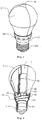
- the LED lamp according to the first embodiment comprises an electrical connector 1, a connecting piece 2 connected to the electrical connector 1 and translucent covers 3 connected to the connecting piece 2.
- the electrical connector 1 is provided with a driver 11 therein.
- the driver 11 is connected to an external power through the electrical connector 1.
- the connecting piece 2 is connected and fixed to the electrical connector 1 at its bottom, and there is a cavity 21 formed within the connecting piece 2 for ventilation.
- At least two translucent cover 3 are fixed and connected to the top of the connecting piece 2.
- the at least two translucent cover 3 interconnect and enclose into an overall lampshade, and each of the translucent cover 3 has a cavity formed therein.
- a channel 4 which extends vertically and has openings in communication with the outside at its both ends, is enclosed between the at least two translucent covers 3.
- the bottom of the translucent cover 3 is fixed and connected to the connecting piece 2, i.e., one end of the channel 4 is connected to the connecting piece 2.
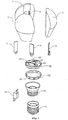
- the connecting piece 2 is provided with a through-hole 22, which connects the channel 4 and the cavity 21, at its top.
- the connecting piece 2 is provided with ventilation holes 26 which is in communication with the outer environment, and the ventilation holes 26 is connect to the cavity 21.
- Light-emitting plates 5 are fixed to the portions of the translucent covers 3 that enclose the channel 4.
- the portions of the translucent cover 3 that enclose the channel 4 are provided with gaps 31 for fixing the light-emitting plates 5.
- a plurality of LED light-emitting elements are fixed on the side surface of the light-emitting plate 5 that face to the outer surface of the translucent cover 3.
- the plurality of the LED light-emitting elements are connected to the driver 11 within the electrical connector 1 by the connecting lines through the connecting piece 2.
- the side edges of the gap 31 are provided with grooves for fixing the light-emitting plate 5. That is, the light-emitting plates 5 are located on the circumferential surface of the channel 4 and enclose the channel 4. Therefore, the LED light-emitting elements included in the light-emitting plates 5 could implement 360 degree illumination in various directions, such that omnidirectional illumination are realized.
- the light-emitting plate may also be omitted and the LED light-emitting elements are directly fixed on the surface of the portion of the translucent cover 3 that is close to the channel 4 which faces to the outside of the translucent cover 3.
- the channel like this and the channel through which a convection between the cavity within the connecting piece and the outside air is formed could implement heat dissipation, such that the heat generated from the plurality of LED light-emitting elements could be transferred out, thereby implementing omnidirectional illumination of the LED lamp and meeting the requirement for its heat dissipation.
- the light-emitting plate 5 can be made of transparent material such as glass, ceramic, plastic and the like, or opaque material such as metal.
- the surface of the light-emitting plate 5 that is provided with LED light-emitting elements is coated with a reflective layer.
- the LED light-emitting element may be LED chip or SMD LED, or may be directly formed on the light-emitting body 3 through the processes including attaching powder, bonding dies and bonding wires. Various forms are possible.
- the LED light-emitting elements may be arranged on the surface of the translucent cover that is close to the channel 4, or may be on the outer surface of the translucent cover as long as their light-emitting surfaces face to the cavity formed by the translucent cover 3.
- the connecting piece 2 comprises : a connecting portion 23 connected to the electrical connector 1 by means of screw thread, direct plug-in and the like; a bottom cap 24 fixed on the connecting portion 23 and separating the electrical connector 1 from the cavity 21 within the connecting piece 2; and a top cap 25 connected to the bottom cap 24 to form a cavity 21.
- the through-hole 22 is provided on the top cap 25.
- the ventilation holes 26 are provided on the side surface of the connecting piece 2, i.e., the side circumferential surface of the bottom cap 24, and arranged evenly spaced along the circumferential surface.
- the top cap 25 is provided with a stop plate 27 extending upward along the periphery of the through-hole 22, and positioning plates 28 located outside the stop plate 27 and separated from the stop plate 27 with a space.
- the positioning plates 28 are fixed on the top cap 25.
- the stop plate 27 and the positioning plates 28 are used to lock the bottom of the translucent cover 3 into the space between them so as to fix the translucent cover 3 on the top cap 25.
- the at least two translucent cover 3 according to this embodiment enclose into an integrity with an incandescent lamp shape.
- the through-hole 22 is a triangular hole.
- the number of the translucent covers 3 is three.
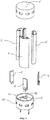
- Fig. 4 and Fig. 5 omitting the electrical connector, illustrate the second embodiments of the present invention.
- the connecting piece 2' connected to the electrical connector in this embodiment is hollow cylinder-shaped and provided with two separating plates perpendicular to its axial direction therein to define the cavity 21'.
- One of the separating plates is provided with a though-hole 22'.
- the portion of the circumferential surface that corresponds to the cavity 21' is provided with ventilation holes 26'.
- the ventilation holes 26' are evenly spaced on the portion of the circumferential surface of the connecting piece that corresponds to the cavity 21'.
- the separating plate with the through-hole 22' is provided with a stop plate 27' protruding upward along the periphery of the through-hole 22' which is used to fix at least two translucent covers 3'.
- the translucent covers 3' is strip-shaped and has a plane surface at one side and a curved surface with arc-shaped section at the other side.
- the curved surfaces of the at least two translucent covers 3' join together to form a long cylinder-shaped lampshade.
- the plane surfaces of the translucent cover 3' join together to enclose a hollow channel 4' extending vertically.
- the channel 4' has openings at its two ends, and its bottom is fixed to the through-hole 22'.
- the surface of the translucent cover 3' that faces to the channel 4' i.e., the plane surface, has a light-emitting plate 5' fixed on it.
- this surface has a gap for accommodating the light-emitting plate 5' .
- the surface of the light-emitting plate 5' that faces outward, i.e., the surface toward the cavity of the translucent cover 3', has a plurality of LED light-emitting elements fixed on it.
- the LED light-emitting elements are connected to the pins on the connecting piece 2' through connecting lines and thereby connected to the external electrical connector through the pins.
- the light-emitting plate 5' may be omitted and the LED light-emitting elements may also be directly fixed on the surface of the translucent cover 3' that encloses the channel 4' .
- the LED light-emitting elements may also be fixed on the outer surface of the translucent cover 3' with the light-emitting surface toward the cavity.
- the second connecting piece 2" also has a cavity like the first connecting piece 2'.
- One end of the cavity is in communication with the through-hole 22', and the circumferential surface of the cavity has ventilation holes 26" in communication with the outside.
- the second connecting piece 2" also has connecting line connecting the LED light-emitting elements and the pins thereon.
- the above LED lamp has at least two translucent covers which joint together to form an integrity, and a channel is formed between the translucent covers.
- One end of the channel is in communication with the outside through the connecting piece, and the other end is in communication with the outside directly.
- both ends could be in communication with the outside through the connecting piece to form a channel for convection to dissipate the heat.
- This LED lamp implements 360 degree omnidirectional illumination with large light-emitting angle and high light-emitting efficiency, and has good heat dissipation performance, thereby increasing the service life of the LED lamp.
- the translucent covers of this LED lamp could be combined into a lampshade with various lengths or various shapes as required, and its processing is facilitated, thereby widening the range of applications of the LED lamp.
Claims (6)
- Lampe à DEL à émission de lumière omnidirectionnelle, comprenant un connecteur électrique (1) avec un circuit d'attaque (11) à l'intérieur, une pièce de connexion (2) connectée au connecteur électrique (1) et des recouvrements translucides (3) raccordés à la pièce de connexion (2),
lampe dans laquelle
les recouvrements translucides (3) comprennent au moins deux recouvrements translucides, et la pluralité de recouvrements translucides (3) se rejoignent et enferment un espace en forme d'abat-jour complet;
un canal (4) est enfermé entre les recouvrements translucides (3), des ouvertures aux deux extrémités du canal (4) sont en communication avec l'extérieur, la pièce de connexion (2) est fixée sur les recouvrements translucides (3) à au moins une extrémité du canal (4), une cavité est formée à l'intérieur de la pièce de connexion (2), la cavité de la pièce de connexion (2) est en communication avec le canal (4) entre les recouvrements translucides (3), et des orifices de ventilation (26) en communication avec l'extérieur sont prévus sur la pièce de connexion (2); et
les recouvrements translucides (3) présentent des éléments de transmission de lumière à DEL fixés sur eux, les surfaces émettrices de lumière des éléments émetteurs de lumière à DEL donnent sur une chambre formée par les recouvrements translucides, et les éléments émetteurs de lumière à DEL sont connectés au circuit d'attaque (11) dans le connecteur électrique (1) par l'intermédiaire de lignes de connexion, où les recouvrements translucides (3) sont fixés et raccordés à la pièce de connexion (2) à une extrémité du canal, la pièce de connexion (2) est fixée à la partie supérieure du connecteur électrique (1), les recouvrements translucides (3) sont raccordés à la partie supérieure de la pièce de connexion (2), les recouvrements translucides (3) enferment un espace en forme d' ampoule, le sommet de la pièce de connexion (2) présente un orifice de passage (22) en communication avec le canal (4), et les orifices de ventilation (26) sont prévus sur la surface latérale de la pièce de connexion (2), caractérisée en ce que la pièce de connexion (2) comprend une partie de connexion (23) connectée au connecteur électrique (1), un couvercle inférieur (24) fixé sur la partie de connexion (2) et séparant le connecteur électrique d'une cavité (21) à l'intérieur de la pièce de connexion (2), et un couvercle supérieur (25) raccordé au couvercle inférieur (24) pour former la cavité (21), les orifices de ventilation (26) sont prévus la surface circonférentielle latérale du couvercle inférieur (24) et sont espacés uniformément le long de la surface circonférentielle, et l'orifice de passage (22) est prévu sur le couvercle supérieur (25). - Lampe à DEL à émission de lumière omnidirectionnelle selon la revendication 1, caractérisée en ce que: la partie du recouvrement translucide qui referme le canal (4) présente un vide (31) dans lequel une plaque émettrice de lumière (5) est fixée, et les éléments émetteurs de lumière sont fixés sur la plaque émettrice de lumière (5).
- Lampe à DEL à émission de lumière omnidirectionnelle selon la revendication 1, caractérisée en ce que: le couvercle supérieur (25) est pourvu d'une plaque d'arrêt (27) s'étendant vers le haut le long de la périphérie de l'orifice de passage (22), le couvercle supérieur (25) est également muni de plaques de positionnement (28) fixées en dehors de la plaque d'arrêt (27) et séparées de la plaque d'arrêt (27) par un espace, le fond des couvercles translucides (3) est verrouillé et fixé dans l'espace compris entre la plaque d'arrêt (27) et la plaque de positionnement (28).
- Lampe à DEL à émission de lumière omnidirectionnelle selon la revendication 1 ou 2, caractérisée en ce que: les recouvrements translucides (3) renferment une forme de tube en bande, des deux extrémités du canal enfermé par les recouvrements translucides (3) sont connectés et fixés aux pièces de connexion (2), la pièce de connexion (2) est creuse et de forme cylindrique et comprend deux plaques de séparation perpendiculaires à sa direction axiale afin de définir la cavité (21), la surface latérale de la pièce de connexion (2) qui a la cavité (21) est munie des orifices de ventilation (26), la plaque de séparation à une extrémité de la pièce de connexion (2) est munie de l'orifice de passage (22) en communication avec le canal (4), et l'autre extrémité de la pièce de connexion est munie de broches qui sont connectées au connecteur électrique (1).
- Lampe à DEL à émission de lumière omnidirectionnelle selon la revendication 2, caractérisée en ce que: la surface de la plaque émettrice de lumière (5) qui est munie d'éléments émetteurs de lumière à DEL est revêtue d'une couche réfléchissante.
- Lampe à DEL à émission de lumière omnidirectionnelle selon la revendication 2, caractérisée en ce que: les bords latéraux du vide (31) sont munis de rainures destinées à fixer la plaque émettrice de lumière (5).
Applications Claiming Priority (2)
| Application Number | Priority Date | Filing Date | Title |
|---|---|---|---|
| CN201410552841.3A CN104295968A (zh) | 2014-10-17 | 2014-10-17 | 一种全方位出光led灯 |
| PCT/CN2015/000695 WO2016058286A1 (fr) | 2014-10-17 | 2015-10-14 | Lampe à del à émission de lumière omnidirectionnelle |
Publications (3)
| Publication Number | Publication Date |
|---|---|
| EP3208522A1 EP3208522A1 (fr) | 2017-08-23 |
| EP3208522A4 EP3208522A4 (fr) | 2018-03-14 |
| EP3208522B1 true EP3208522B1 (fr) | 2019-10-30 |
Family
ID=52315814
Family Applications (1)
| Application Number | Title | Priority Date | Filing Date |
|---|---|---|---|
| EP15851023.0A Active EP3208522B1 (fr) | 2014-10-17 | 2015-10-14 | Lampe à del à émission de lumière omnidirectionnelle |
Country Status (6)
| Country | Link |
|---|---|
| US (1) | US10197263B2 (fr) |
| EP (1) | EP3208522B1 (fr) |
| CN (1) | CN104295968A (fr) |
| AU (1) | AU2015333473B2 (fr) |
| CA (1) | CA2964495A1 (fr) |
| WO (1) | WO2016058286A1 (fr) |
Families Citing this family (7)
| Publication number | Priority date | Publication date | Assignee | Title |
|---|---|---|---|---|
| CN104295968A (zh) | 2014-10-17 | 2015-01-21 | 杨志伟 | 一种全方位出光led灯 |
| CN105987311A (zh) * | 2015-02-27 | 2016-10-05 | 集优光电股份有限公司 | 发光二极体灯泡 |
| CN105179974A (zh) * | 2015-10-12 | 2015-12-23 | 上海昭关照明实业有限公司 | 一种led灯 |
| CN106151889B (zh) * | 2016-07-03 | 2018-12-18 | 江苏京煦光电科技有限公司 | 带有匀光透镜的智能led灯 |
| CN106195652A (zh) * | 2016-07-03 | 2016-12-07 | 彭曙光 | 自散热智能led灯 |
| WO2019127515A1 (fr) * | 2017-12-29 | 2019-07-04 | 深圳市超频三科技股份有限公司 | Lampe et substrat de source de lumière |
| US10739513B2 (en) * | 2018-08-31 | 2020-08-11 | RAB Lighting Inc. | Apparatuses and methods for efficiently directing light toward and away from a mounting surface |
Family Cites Families (24)
| Publication number | Priority date | Publication date | Assignee | Title |
|---|---|---|---|---|
| CN101532609B (zh) | 2008-03-13 | 2010-12-01 | 淄博诺达网络科技有限公司 | 微电脑交流大功率三基色led照明节能灯 |
| US9030120B2 (en) * | 2009-10-20 | 2015-05-12 | Cree, Inc. | Heat sinks and lamp incorporating same |
| US9217542B2 (en) * | 2009-10-20 | 2015-12-22 | Cree, Inc. | Heat sinks and lamp incorporating same |
| WO2011118992A2 (fr) * | 2010-03-26 | 2011-09-29 | 주식회사 솔라코 컴퍼니 | Module d'éclairage à del et lampe d'éclairage le comprenant |
| CN102022651A (zh) | 2010-12-21 | 2011-04-20 | 东莞市华胜展鸿电子科技有限公司 | Led日光灯 |
| CN102679185A (zh) * | 2011-03-09 | 2012-09-19 | 旭丽电子(广州)有限公司 | 具内部流道的灯具 |
| US20130088848A1 (en) * | 2011-10-06 | 2013-04-11 | Intematix Corporation | Solid-state lamps with improved radial emission and thermal performance |
| US9500355B2 (en) * | 2012-05-04 | 2016-11-22 | GE Lighting Solutions, LLC | Lamp with light emitting elements surrounding active cooling device |
| CN202769327U (zh) * | 2012-07-02 | 2013-03-06 | 沈李豪 | 一种led灯 |
| CN202660330U (zh) * | 2012-07-04 | 2013-01-09 | 扬州承炜照明科技有限公司 | 一种led灯泡 |
| KR101412834B1 (ko) * | 2012-08-10 | 2014-07-08 | (주)파트너 | 엘이디 조명등 |
| CN102900981B (zh) * | 2012-09-29 | 2015-09-02 | 宁波同泰电气股份有限公司 | 电源外置式的可旋转led双面日光灯 |
| JP5818167B2 (ja) | 2012-11-01 | 2015-11-18 | 岩崎電気株式会社 | Ledランプ |
| CN203010265U (zh) * | 2012-11-30 | 2013-06-19 | 四川柏狮光电技术有限公司 | 一种分体式360度发光的led球泡灯 |
| CN203131507U (zh) | 2013-02-05 | 2013-08-14 | 沈李豪 | 一种中空侧对流散热的led灯 |
| US20140340899A1 (en) * | 2013-05-18 | 2014-11-20 | Edward E. Bailey | Integrated Solid-State Lamp |
| CN103574357B (zh) * | 2013-05-21 | 2016-01-20 | 香港应用科技研究院有限公司 | 全向发光和高效散热的照明装置 |
| CN203249216U (zh) * | 2013-05-22 | 2013-10-23 | 北京铨富光电科技有限公司 | Led灯泡的气体热对流散热结构 |
| CN103244933A (zh) | 2013-05-28 | 2013-08-14 | 浙江名芯半导体科技有限公司 | 带有内部对流散热结构的led灯泡及led光源设备 |
| CN203323008U (zh) * | 2013-06-27 | 2013-12-04 | 本科照明有限公司 | 一种双面发光led球泡灯 |
| CN203322814U (zh) * | 2013-06-27 | 2013-12-04 | 本科照明有限公司 | 一种大角度led球泡灯 |
| US20150077994A1 (en) * | 2013-09-16 | 2015-03-19 | Tai Ming Green Power Co., Ltd. | Structure of led light |
| CN204284986U (zh) * | 2014-10-17 | 2015-04-22 | 杨志伟 | 一种全方位出光led灯 |
| CN104295968A (zh) | 2014-10-17 | 2015-01-21 | 杨志伟 | 一种全方位出光led灯 |
-
2014
- 2014-10-17 CN CN201410552841.3A patent/CN104295968A/zh active Pending
-
2015
- 2015-10-14 CA CA2964495A patent/CA2964495A1/fr not_active Abandoned
- 2015-10-14 US US15/519,451 patent/US10197263B2/en active Active
- 2015-10-14 WO PCT/CN2015/000695 patent/WO2016058286A1/fr active Application Filing
- 2015-10-14 AU AU2015333473A patent/AU2015333473B2/en not_active Ceased
- 2015-10-14 EP EP15851023.0A patent/EP3208522B1/fr active Active
Non-Patent Citations (1)
| Title |
|---|
| None * |
Also Published As
| Publication number | Publication date |
|---|---|
| WO2016058286A1 (fr) | 2016-04-21 |
| EP3208522A1 (fr) | 2017-08-23 |
| AU2015333473B2 (en) | 2018-04-26 |
| US20170234521A1 (en) | 2017-08-17 |
| US10197263B2 (en) | 2019-02-05 |
| EP3208522A4 (fr) | 2018-03-14 |
| CN104295968A (zh) | 2015-01-21 |
| CA2964495A1 (fr) | 2016-04-21 |
| AU2015333473A1 (en) | 2017-05-18 |
Similar Documents
| Publication | Publication Date | Title |
|---|---|---|
| EP3208522B1 (fr) | Lampe à del à émission de lumière omnidirectionnelle | |
| US10107487B2 (en) | LED light bulbs | |
| JP3171402U (ja) | 照明装置 | |
| JP5625203B2 (ja) | ブロック組立構造を有するled照明装置 | |
| KR101278258B1 (ko) | 메인 조명으로부터 구별되는 외관을 가진 램프 | |
| JP2010055993A (ja) | 照明装置および照明器具 | |
| WO2012032951A1 (fr) | Lampe à base métallique et équipement d'éclairage | |
| US20170234519A1 (en) | Led lamp unit | |
| JP2013219004A (ja) | 蛍光灯取付具に使用するためのledライト管 | |
| TW201348646A (zh) | 發光二極體燈具 | |
| JP2017045951A (ja) | Ledモジュール及びそれを備えた照明器具 | |
| JP3164034U (ja) | Led照明装置 | |
| JP2012226892A (ja) | 照明装置および照明器具 | |
| AU2016247786A1 (en) | Luminaire housing | |
| JP5802497B2 (ja) | 電球型照明装置 | |
| JP3163443U (ja) | Led式照明装置 | |
| TWM436134U (en) | Light emitting device and lampshade thereof | |
| WO2013107731A1 (fr) | Dispositif d'éclairage et luminaire en disposant | |
| US8789976B2 (en) | Integrated multi-layered illuminating unit and integrated multi-layered illuminating assembling unit | |
| EP4105545A1 (fr) | Capot de lampe électroluminescente omnidirectionnelle et ampoule électrique le comportant | |
| CN102913792A (zh) | 照明led灯 | |
| TW201812207A (zh) | 照明裝置 | |
| JP2011210513A (ja) | ミニクリプトンランプ型led電球 | |
| JP2012074344A (ja) | 照明装置、口金付ランプおよび照明器具 | |
| KR20150088616A (ko) | 엘이디 전구 |
Legal Events
| Date | Code | Title | Description |
|---|---|---|---|
| STAA | Information on the status of an ep patent application or granted ep patent |
Free format text: STATUS: THE INTERNATIONAL PUBLICATION HAS BEEN MADE |
|
| PUAI | Public reference made under article 153(3) epc to a published international application that has entered the european phase |
Free format text: ORIGINAL CODE: 0009012 |
|
| STAA | Information on the status of an ep patent application or granted ep patent |
Free format text: STATUS: REQUEST FOR EXAMINATION WAS MADE |
|
| 17P | Request for examination filed |
Effective date: 20170509 |
|
| AK | Designated contracting states |
Kind code of ref document: A1 Designated state(s): AL AT BE BG CH CY CZ DE DK EE ES FI FR GB GR HR HU IE IS IT LI LT LU LV MC MK MT NL NO PL PT RO RS SE SI SK SM TR |
|
| AX | Request for extension of the european patent |
Extension state: BA ME |
|
| DAV | Request for validation of the european patent (deleted) | ||
| DAX | Request for extension of the european patent (deleted) | ||
| A4 | Supplementary search report drawn up and despatched |
Effective date: 20180209 |
|
| RIC1 | Information provided on ipc code assigned before grant |
Ipc: F21V 21/00 20060101ALI20180205BHEP Ipc: F21V 3/00 20150101ALI20180205BHEP Ipc: F21V 19/00 20060101ALI20180205BHEP Ipc: F21V 29/83 20150101ALI20180205BHEP Ipc: F21S 2/00 20160101AFI20180205BHEP |
|
| GRAP | Despatch of communication of intention to grant a patent |
Free format text: ORIGINAL CODE: EPIDOSNIGR1 |
|
| STAA | Information on the status of an ep patent application or granted ep patent |
Free format text: STATUS: GRANT OF PATENT IS INTENDED |
|
| INTG | Intention to grant announced |
Effective date: 20190520 |
|
| RIN1 | Information on inventor provided before grant (corrected) |
Inventor name: YEUNG, CHIWAI |
|
| GRAS | Grant fee paid |
Free format text: ORIGINAL CODE: EPIDOSNIGR3 |
|
| GRAA | (expected) grant |
Free format text: ORIGINAL CODE: 0009210 |
|
| STAA | Information on the status of an ep patent application or granted ep patent |
Free format text: STATUS: THE PATENT HAS BEEN GRANTED |
|
| AK | Designated contracting states |
Kind code of ref document: B1 Designated state(s): AL AT BE BG CH CY CZ DE DK EE ES FI FR GB GR HR HU IE IS IT LI LT LU LV MC MK MT NL NO PL PT RO RS SE SI SK SM TR |
|
| REG | Reference to a national code |
Ref country code: GB Ref legal event code: FG4D |
|
| REG | Reference to a national code |
Ref country code: CH Ref legal event code: EP |
|
| REG | Reference to a national code |
Ref country code: AT Ref legal event code: REF Ref document number: 1196540 Country of ref document: AT Kind code of ref document: T Effective date: 20191115 |
|
| REG | Reference to a national code |
Ref country code: DE Ref legal event code: R096 Ref document number: 602015040860 Country of ref document: DE |
|
| REG | Reference to a national code |
Ref country code: IE Ref legal event code: FG4D |
|
| REG | Reference to a national code |
Ref country code: NL Ref legal event code: FP |
|
| REG | Reference to a national code |
Ref country code: LT Ref legal event code: MG4D |
|
| PG25 | Lapsed in a contracting state [announced via postgrant information from national office to epo] |
Ref country code: PL Free format text: LAPSE BECAUSE OF FAILURE TO SUBMIT A TRANSLATION OF THE DESCRIPTION OR TO PAY THE FEE WITHIN THE PRESCRIBED TIME-LIMIT Effective date: 20191030 Ref country code: LV Free format text: LAPSE BECAUSE OF FAILURE TO SUBMIT A TRANSLATION OF THE DESCRIPTION OR TO PAY THE FEE WITHIN THE PRESCRIBED TIME-LIMIT Effective date: 20191030 Ref country code: SE Free format text: LAPSE BECAUSE OF FAILURE TO SUBMIT A TRANSLATION OF THE DESCRIPTION OR TO PAY THE FEE WITHIN THE PRESCRIBED TIME-LIMIT Effective date: 20191030 Ref country code: BG Free format text: LAPSE BECAUSE OF FAILURE TO SUBMIT A TRANSLATION OF THE DESCRIPTION OR TO PAY THE FEE WITHIN THE PRESCRIBED TIME-LIMIT Effective date: 20200130 Ref country code: FI Free format text: LAPSE BECAUSE OF FAILURE TO SUBMIT A TRANSLATION OF THE DESCRIPTION OR TO PAY THE FEE WITHIN THE PRESCRIBED TIME-LIMIT Effective date: 20191030 Ref country code: PT Free format text: LAPSE BECAUSE OF FAILURE TO SUBMIT A TRANSLATION OF THE DESCRIPTION OR TO PAY THE FEE WITHIN THE PRESCRIBED TIME-LIMIT Effective date: 20200302 Ref country code: NO Free format text: LAPSE BECAUSE OF FAILURE TO SUBMIT A TRANSLATION OF THE DESCRIPTION OR TO PAY THE FEE WITHIN THE PRESCRIBED TIME-LIMIT Effective date: 20200130 Ref country code: GR Free format text: LAPSE BECAUSE OF FAILURE TO SUBMIT A TRANSLATION OF THE DESCRIPTION OR TO PAY THE FEE WITHIN THE PRESCRIBED TIME-LIMIT Effective date: 20200131 Ref country code: LT Free format text: LAPSE BECAUSE OF FAILURE TO SUBMIT A TRANSLATION OF THE DESCRIPTION OR TO PAY THE FEE WITHIN THE PRESCRIBED TIME-LIMIT Effective date: 20191030 |
|
| PG25 | Lapsed in a contracting state [announced via postgrant information from national office to epo] |
Ref country code: RS Free format text: LAPSE BECAUSE OF FAILURE TO SUBMIT A TRANSLATION OF THE DESCRIPTION OR TO PAY THE FEE WITHIN THE PRESCRIBED TIME-LIMIT Effective date: 20191030 Ref country code: IS Free format text: LAPSE BECAUSE OF FAILURE TO SUBMIT A TRANSLATION OF THE DESCRIPTION OR TO PAY THE FEE WITHIN THE PRESCRIBED TIME-LIMIT Effective date: 20200229 Ref country code: HR Free format text: LAPSE BECAUSE OF FAILURE TO SUBMIT A TRANSLATION OF THE DESCRIPTION OR TO PAY THE FEE WITHIN THE PRESCRIBED TIME-LIMIT Effective date: 20191030 |
|
| PG25 | Lapsed in a contracting state [announced via postgrant information from national office to epo] |
Ref country code: AL Free format text: LAPSE BECAUSE OF FAILURE TO SUBMIT A TRANSLATION OF THE DESCRIPTION OR TO PAY THE FEE WITHIN THE PRESCRIBED TIME-LIMIT Effective date: 20191030 |
|
| PG25 | Lapsed in a contracting state [announced via postgrant information from national office to epo] |
Ref country code: RO Free format text: LAPSE BECAUSE OF FAILURE TO SUBMIT A TRANSLATION OF THE DESCRIPTION OR TO PAY THE FEE WITHIN THE PRESCRIBED TIME-LIMIT Effective date: 20191030 Ref country code: CZ Free format text: LAPSE BECAUSE OF FAILURE TO SUBMIT A TRANSLATION OF THE DESCRIPTION OR TO PAY THE FEE WITHIN THE PRESCRIBED TIME-LIMIT Effective date: 20191030 Ref country code: DK Free format text: LAPSE BECAUSE OF FAILURE TO SUBMIT A TRANSLATION OF THE DESCRIPTION OR TO PAY THE FEE WITHIN THE PRESCRIBED TIME-LIMIT Effective date: 20191030 Ref country code: EE Free format text: LAPSE BECAUSE OF FAILURE TO SUBMIT A TRANSLATION OF THE DESCRIPTION OR TO PAY THE FEE WITHIN THE PRESCRIBED TIME-LIMIT Effective date: 20191030 |
|
| REG | Reference to a national code |
Ref country code: DE Ref legal event code: R097 Ref document number: 602015040860 Country of ref document: DE |
|
| REG | Reference to a national code |
Ref country code: AT Ref legal event code: MK05 Ref document number: 1196540 Country of ref document: AT Kind code of ref document: T Effective date: 20191030 |
|
| PG25 | Lapsed in a contracting state [announced via postgrant information from national office to epo] |
Ref country code: IT Free format text: LAPSE BECAUSE OF FAILURE TO SUBMIT A TRANSLATION OF THE DESCRIPTION OR TO PAY THE FEE WITHIN THE PRESCRIBED TIME-LIMIT Effective date: 20191030 Ref country code: SM Free format text: LAPSE BECAUSE OF FAILURE TO SUBMIT A TRANSLATION OF THE DESCRIPTION OR TO PAY THE FEE WITHIN THE PRESCRIBED TIME-LIMIT Effective date: 20191030 Ref country code: SK Free format text: LAPSE BECAUSE OF FAILURE TO SUBMIT A TRANSLATION OF THE DESCRIPTION OR TO PAY THE FEE WITHIN THE PRESCRIBED TIME-LIMIT Effective date: 20191030 |
|
| PLBE | No opposition filed within time limit |
Free format text: ORIGINAL CODE: 0009261 |
|
| STAA | Information on the status of an ep patent application or granted ep patent |
Free format text: STATUS: NO OPPOSITION FILED WITHIN TIME LIMIT |
|
| 26N | No opposition filed |
Effective date: 20200731 |
|
| PG25 | Lapsed in a contracting state [announced via postgrant information from national office to epo] |
Ref country code: ES Free format text: LAPSE BECAUSE OF FAILURE TO SUBMIT A TRANSLATION OF THE DESCRIPTION OR TO PAY THE FEE WITHIN THE PRESCRIBED TIME-LIMIT Effective date: 20191030 |
|
| PG25 | Lapsed in a contracting state [announced via postgrant information from national office to epo] |
Ref country code: AT Free format text: LAPSE BECAUSE OF FAILURE TO SUBMIT A TRANSLATION OF THE DESCRIPTION OR TO PAY THE FEE WITHIN THE PRESCRIBED TIME-LIMIT Effective date: 20191030 Ref country code: SI Free format text: LAPSE BECAUSE OF FAILURE TO SUBMIT A TRANSLATION OF THE DESCRIPTION OR TO PAY THE FEE WITHIN THE PRESCRIBED TIME-LIMIT Effective date: 20191030 |
|
| REG | Reference to a national code |
Ref country code: CH Ref legal event code: PL |
|
| PG25 | Lapsed in a contracting state [announced via postgrant information from national office to epo] |
Ref country code: MC Free format text: LAPSE BECAUSE OF FAILURE TO SUBMIT A TRANSLATION OF THE DESCRIPTION OR TO PAY THE FEE WITHIN THE PRESCRIBED TIME-LIMIT Effective date: 20191030 Ref country code: LU Free format text: LAPSE BECAUSE OF NON-PAYMENT OF DUE FEES Effective date: 20201014 |
|
| PG25 | Lapsed in a contracting state [announced via postgrant information from national office to epo] |
Ref country code: CH Free format text: LAPSE BECAUSE OF NON-PAYMENT OF DUE FEES Effective date: 20201031 Ref country code: LI Free format text: LAPSE BECAUSE OF NON-PAYMENT OF DUE FEES Effective date: 20201031 |
|
| PG25 | Lapsed in a contracting state [announced via postgrant information from national office to epo] |
Ref country code: IE Free format text: LAPSE BECAUSE OF NON-PAYMENT OF DUE FEES Effective date: 20201014 |
|
| PG25 | Lapsed in a contracting state [announced via postgrant information from national office to epo] |
Ref country code: TR Free format text: LAPSE BECAUSE OF FAILURE TO SUBMIT A TRANSLATION OF THE DESCRIPTION OR TO PAY THE FEE WITHIN THE PRESCRIBED TIME-LIMIT Effective date: 20191030 Ref country code: MT Free format text: LAPSE BECAUSE OF FAILURE TO SUBMIT A TRANSLATION OF THE DESCRIPTION OR TO PAY THE FEE WITHIN THE PRESCRIBED TIME-LIMIT Effective date: 20191030 Ref country code: CY Free format text: LAPSE BECAUSE OF FAILURE TO SUBMIT A TRANSLATION OF THE DESCRIPTION OR TO PAY THE FEE WITHIN THE PRESCRIBED TIME-LIMIT Effective date: 20191030 |
|
| PG25 | Lapsed in a contracting state [announced via postgrant information from national office to epo] |
Ref country code: MK Free format text: LAPSE BECAUSE OF FAILURE TO SUBMIT A TRANSLATION OF THE DESCRIPTION OR TO PAY THE FEE WITHIN THE PRESCRIBED TIME-LIMIT Effective date: 20191030 |
|
| PGFP | Annual fee paid to national office [announced via postgrant information from national office to epo] |
Ref country code: NL Payment date: 20231027 Year of fee payment: 9 |
|
| PGFP | Annual fee paid to national office [announced via postgrant information from national office to epo] |
Ref country code: GB Payment date: 20231027 Year of fee payment: 9 |
|
| PGFP | Annual fee paid to national office [announced via postgrant information from national office to epo] |
Ref country code: FR Payment date: 20231027 Year of fee payment: 9 Ref country code: DE Payment date: 20231027 Year of fee payment: 9 |
|
| PGFP | Annual fee paid to national office [announced via postgrant information from national office to epo] |
Ref country code: BE Payment date: 20231030 Year of fee payment: 9 |