EP3208121A1 - Belüftungssystem für fahrzeug mit einer verschlusskappe - Google Patents
Belüftungssystem für fahrzeug mit einer verschlusskappe Download PDFInfo
- Publication number
- EP3208121A1 EP3208121A1 EP17154874.6A EP17154874A EP3208121A1 EP 3208121 A1 EP3208121 A1 EP 3208121A1 EP 17154874 A EP17154874 A EP 17154874A EP 3208121 A1 EP3208121 A1 EP 3208121A1
- Authority
- EP
- European Patent Office
- Prior art keywords
- shutter
- movable flap
- air
- ventilation system
- wall
- Prior art date
- Legal status (The legal status is an assumption and is not a legal conclusion. Google has not performed a legal analysis and makes no representation as to the accuracy of the status listed.)
- Withdrawn
Links
Images


Classifications
-
- B—PERFORMING OPERATIONS; TRANSPORTING
- B60—VEHICLES IN GENERAL
- B60H—ARRANGEMENTS OF HEATING, COOLING, VENTILATING OR OTHER AIR-TREATING DEVICES SPECIALLY ADAPTED FOR PASSENGER OR GOODS SPACES OF VEHICLES
- B60H1/00—Heating, cooling or ventilating [HVAC] devices
- B60H1/00507—Details, e.g. mounting arrangements, desaeration devices
- B60H1/00514—Details of air conditioning housings
- B60H1/00542—Modular assemblies
-
- B—PERFORMING OPERATIONS; TRANSPORTING
- B60—VEHICLES IN GENERAL
- B60H—ARRANGEMENTS OF HEATING, COOLING, VENTILATING OR OTHER AIR-TREATING DEVICES SPECIALLY ADAPTED FOR PASSENGER OR GOODS SPACES OF VEHICLES
- B60H1/00—Heating, cooling or ventilating [HVAC] devices
- B60H1/00507—Details, e.g. mounting arrangements, desaeration devices
- B60H1/00592—Add-on devices, e.g. heat/cooling boxes, compartment dividers, upgrade sets
Definitions
- the invention relates to a shutter for closing the ventilation duct of a vehicle ventilation system.
- the document FR 2 813 560 proposes a heating and air conditioning installation whose air flow can be regulated by a movable flap and in which a connection section can be closed if necessary.
- This system has the disadvantage of being bulky because of the large distance between the movable flap of the installation and the shutter closing the connection section.
- An object of the invention is therefore to solve this problem, namely to provide a shutter for a compact ventilation system, without interfering with the operation of the movable flap.
- a first aspect of the invention relates to a shutter for a vehicle ventilation system, comprising a wall arranged to close a duct of said ventilation system, characterized in that said wall comprises at least one flexible portion arranged to be deformed during a contact between the wall and a movable flap of said ventilation system, to allow complete displacement of said movable flap.
- This flexible portion therefore allows the complete opening of a movable flap in cases where, due to space constraints and manufacturing, it is possible to position the shutter in a position necessarily inducing interference with the mobile shutter.
- the ventilation system accommodating the shutter according to the present invention is therefore more compact than the ventilation systems of the state of the art, since the shutter can be placed closer to the movable flap.
- the closure of one of the air ducts by a shutter of the present invention does not interfere with the flow control of air in the other air ducts.
- said at least one flexible portion is further deformed reversibly by the movable flap of said ventilation system.
- This reversible deformation allows the flexible portion to accept a large number of contacts with the movable flap.
- a suitable material such as a material having elastic properties.
- An example of such a material is an elastomer such as rubber, synthetic polyisoprene, polybutadiene or styrene butadiene copolymer.
- said at least one flexible portion is deformed irreversibly during the first contact with the movable flap. Since this first contact is made after assembly of the ventilation system, a irreversible deformation does not interfere with the assembly or operation of the ventilation system. Such irreversible deformation of the flexible wall makes it possible to avoid subsequent contacts between the mobile flap and the shutter, and thus to avoid the application of a torque linked to these contacts to the control system of the movable flap.
- a flexible portion capable of such irreversible deformation may be made of a flexible material capable of plastic deformation, selected from polymers, paper or cardboard.
- the wall of the shutter comprises a rigid portion in addition to the flexible portion.
- This rigid portion may be made of the same material as the flexible portion, but of greater thickness, or a rigid material.
- a rigid material is a material that is not likely to deform when in contact with the movable flap.
- the rigid portion may be located around a periphery of the flexible portion. This rigid portion contributes to stiffening the wall of the shutter and thus to increase the resistance of this wall to tearing.
- the shutter of the present invention comprises a frame defining a periphery of the flexible portion.
- This frame helps to stiffen the flexible portion of the wall, thus ensuring a higher durability of the shutter due to a better tear strength of the flexible wall.
- this frame allows easy attachment or mounting inside the air duct, for example by gluing, welding, nesting or crushing.
- the frame of the shutter further comprises attachment means adapted to attach to the duct of the ventilation system.
- the shutter of the present invention is airtight. This means that the air flow in the closed pipe can be reduced by at least 95%, preferably at least 99%.
- this frame also comprises a peripheral seal intended to ensure an even better seal with the air duct.
- a second aspect of the present invention relates to a ventilation system comprising at least one movable flap, at least one air duct and at least one shutter comprising a wall arranged to close the air duct, the wall comprising at least a portion flexible arranged to be deformed during a contact between the wall and the movable flap to allow complete movement of said movable flap.
- a ventilation system can be installed both in a vehicle having a large number of air vents, without the shutter, and in a vehicle with few air vents, with one or more air ducts closed. .
- a ventilation system can have a fairly compact construction, for example in two parts with a housing having movable shutters assembled on a flow splitter.
- the shutter of the present invention makes it possible to condemn the air ducts that are not used in certain vehicles without hindering the operation of the movable flaps located in the air ducts used.
- said movable flap is arranged to move from a first position where it is not in contact with said wall to a second position where it is in contact with said wall.
- the first position may be a position where the movable shutter prevents an air flow in the air duct and the second position may be a position where the movable shutter allows a flow of air in the air duct if the shutter is not present.
- the movable flap can allow in its second position a maximum air flow in the air duct if the shutter is not present.
- the flexible portion is deformed by the movable flap when the di movable flap is moved from the first position to the second position.
- the shutter according to the present invention can therefore authorize the complete opening of the movable flap.
- the ventilation system described below is intended for use in any type of passenger vehicle or utility vehicle. Its structure is flexible and can therefore adopt different modes of execution. This ventilation system is intended to work with conventional elements of vehicle ventilation system, including ventilation elements, filtration elements, heating elements and air conditioning elements, which will be omitted from the figures for the sake of clarity .
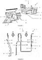
- the ventilation system of Figures 1 and 2 comprises a housing 10 and a flow distributor 20.
- the housing 10 comprises an upper inlet 11 or upstream for admitting air within the ventilation system, for example from ventilation, heating or air conditioning elements. as indicated by the two upper arrows of the Figure 2 .
- the casing 10 further comprises two lower outlets 12 and 13 or downstream intended to expel air towards the flow distributor 20.
- the casing 10 finally comprises two slides 14 intended to assemble the casing 10 to the flow divider 20.
- the flow distributor 20 comprises an upper inlet 21 intended to admit air coming from the housing 10 as well as two lower outlets 22 and 23 intended to be connected to ventilation nozzles in order to expel air towards the interior of a vehicle.
- the flow distributor 20 finally comprises in its upper part two gutters 24 intended to receive the slides 14 of the housing 10.
- the ventilation system 1 is assembled by sliding the flow distributor 20 towards the housing 10 in such a way that the guides 14 of the housing 10 are received in the gutters 24 of the flow distributor 20.
- the assembly by sliding is according to the direction expressed by cross arrows Figures 1 and 2 .
- Line AA 'of the Figure 2 represents the maximum size of the lower outlet 12 to allow the assembly of the ventilation system 1.
- the ventilation system 1 shows two air ducts 2 and 3.
- the air duct 2 must be closed, for example to install the ventilation system 1 in a vehicle requiring few nozzles. ventilation, it is necessary to place a shutter 30 to close the lower outlet 12 of the housing 10, as visible in FIG. Figure 3 .
- this shutter 30 can not be placed beyond the line AA 'visible on the Figure 2 in order not to interfere with the assembly of the ventilation system 1.
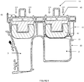
- the housing 10 accommodates movable flaps 40, 45 for regulating the flow of air in each air duct as illustrated in FIGS. Figures 3 to 6 .
- the mobile flap 40 comprises a control shaft 41 as well as closure arms 42, 43.
- the movable flap 40 is capable of adopting a first position in which it is perpendicular to the axis of the air duct 2 and prohibited. the air flow ( Figure 3 ) and a second position in which it is parallel to the axis of the air duct 2 and allow the flow of air in the absence of the shutter 30 ( Figure 4 ).
- the height of the housing 10 is less than the length of the movable flap 40 and the shutter arms 42 and 43 of the movable flap 40 extend beyond the entrance 11 and the air outlet 12 when the movable flap 40 is in the second position visible to the Figure 4 .
- the shutter 30 is at a distance from the control shaft 41 of the movable flap 40 less than half the length of the movable flap 40, or at a distance less than the distance between the shaft for controlling the mobile flap 40 and the end of the movable flap 40 which comes into contact with the wall of the shutter 30.
- the shutter 30 is provided with a wall comprising a flexible portion 31, as visible in FIG. Figure 6 , so that it can be deformed by the movable flap 40, in particular by the closure arm 42. Thanks to this flexible portion 31, the movable flap 40 can reach the second position parallel to the axis of the air duct 2 even when the air duct 2 is closed by the shutter 30.
- the movable flap 45 of the parallel air duct 3 and which shares the same control shaft 41 is not disturbed and can also reach the second position parallel to the axis of the air duct 3 and allow a maximum air flow.
- the flexible portion 31 of the shutter is made of a durable flexible material, such as natural or synthetic elastomers comprising for example rubber, synthetic polyisoprene, polybutadiene or styrene butadiene copolymer.
- the flexible portion 31 may also be made of paper, cardboard or fabric, coated or not.
- the thickness of the flexible portion 31 may be chosen according to the force applied by the movable flap 40 as well as the material. For example, the displacement of the flexible portion 31 during contact with the mobile flap 40 is 0.1 to 1.5 cm.
- the flexible portion 31 can resume its shape when the movable flap moves from the second position to the first position.
- the shutter 30 is substantially sealed. This means that the air flow in the air duct 2 closed by the shutter 30 is reduced by at least 95%, preferably at least 99%.
- a shutter 130 according to a second embodiment is visible at the Figure 7 and comprises a flexible portion 131 similar to the flexible portion 31 according to the first embodiment, and a frame 132 defining a perimeter of the flexible portion 131.
- the frame 132 may be made of the same material as the flexible portion 131 but of greater thickness.
- the frame 132 may be made of a rigid material, such as a plastic such as polypropylene, polyethylene, acrylonitrile-butadiene-styrene copolymer or any other equivalent polymer.
- the frame 132 may also be made of a metal such as steel or aluminum or a composite material.
- the frame 132 confers a greater resistance to the flexible portion 131 and allows the shutter 130 to be fixed in the ventilation system 1 by gluing, welding, interlocking (clipping) or crushing between the casing 10 and the flow distributor 20.
- the frame 132 may also include fastening means (not visible) such as hooks, pads or nesting legs.
- a shutter 230 according to a third embodiment is visible at the Figure 8 and comprises a wall 231 comprising a flexible portion 231a similar to the flexible walls 31 and 131 of the other embodiments and a rigid portion 231b.
- the rigid portion unlike the flexible portion, is made of a material that is not likely to deform when in contact with the movable flap
- the rigid portion 231 b may be made of a rigid material, such as a plastic such as polypropylene, polyethylene, acrylonitrile-butadiene-styrene copolymer or any other equivalent plastic. It can also be made of metal or composite.
- the shutter 230 comprises a frame 232 defining a perimeter of the flexible portion 231.
- the frame 232 is similar to the frame 132.
- the shutter 230 has a reinforced tear resistance and can be adopted in the case of ventilation system with large diameter air ducts.
- a shutter 330 according to a fourth embodiment is visible at the Figure 9 and comprises a flexible portion 331 similar to the flexible walls 31 and 131 of the other embodiments. It comprises a frame 332 defining a perimeter of the flexible portion 331.
- the frame 332 is similar to the frames 132 and 232 but also comprises attachment means in the form of nesting legs 333, intended to be nested / clipped into the housing 10 of the ventilation system 1.
- the frame 232 further comprises a peripheral seal 334 to improve the sealing of the shutter 230, for example to limit the air flow of at least 95 %, preferably at least 99%.
- a shutter comprising a wall having at least one flexible portion makes it possible to close off an air duct even when the space and manufacturing constraints make it necessary to place it at a limited distance from a movable flap of the ventilation system. ventilation, involving interference with this mobile component.
- a flexible portion of a wall of a shutter does not limit the rotation of the movable flaps, which prevents failures of the flow control system and allow a complete opening of the movable shutters located in unobstructed air ducts and embedded on the same control shaft
Applications Claiming Priority (1)
| Application Number | Priority Date | Filing Date | Title |
|---|---|---|---|
| FR1651260A FR3047696B1 (fr) | 2016-02-17 | 2016-02-17 | Obturateur pour systeme de ventilation d’air pour vehicule |
Publications (1)
| Publication Number | Publication Date |
|---|---|
| EP3208121A1 true EP3208121A1 (de) | 2017-08-23 |
Family
ID=55486980
Family Applications (1)
| Application Number | Title | Priority Date | Filing Date |
|---|---|---|---|
| EP17154874.6A Withdrawn EP3208121A1 (de) | 2016-02-17 | 2017-02-06 | Belüftungssystem für fahrzeug mit einer verschlusskappe |
Country Status (2)
| Country | Link |
|---|---|
| EP (1) | EP3208121A1 (de) |
| FR (1) | FR3047696B1 (de) |
Citations (5)
| Publication number | Priority date | Publication date | Assignee | Title |
|---|---|---|---|---|
| JP2001105832A (ja) * | 1999-10-13 | 2001-04-17 | Mitsubishi Heavy Ind Ltd | 車両用空気調和装置 |
| FR2813560A1 (fr) | 2000-08-01 | 2002-03-08 | Behr Gmbh & Co | Installation de chauffage et de climatisation pour un vehicule a moteur |
| US20040185765A1 (en) * | 2003-03-07 | 2004-09-23 | Hidehiko Yamaguchi | Air conditioner for vehicle with noise-reduction means |
| JP2004306743A (ja) * | 2003-04-04 | 2004-11-04 | Denso Corp | 車両用空調装置 |
| DE102012208935A1 (de) * | 2012-05-29 | 2013-12-05 | Eberspächer Climate Control Systems GmbH & Co. KG | Strömungsverdämmungselement, insbesondere zur Luftströmungsverdämmung in einem Luftkanalsystem eines Fahrzeugs |
-
2016
- 2016-02-17 FR FR1651260A patent/FR3047696B1/fr not_active Expired - Fee Related
-
2017
- 2017-02-06 EP EP17154874.6A patent/EP3208121A1/de not_active Withdrawn
Patent Citations (5)
| Publication number | Priority date | Publication date | Assignee | Title |
|---|---|---|---|---|
| JP2001105832A (ja) * | 1999-10-13 | 2001-04-17 | Mitsubishi Heavy Ind Ltd | 車両用空気調和装置 |
| FR2813560A1 (fr) | 2000-08-01 | 2002-03-08 | Behr Gmbh & Co | Installation de chauffage et de climatisation pour un vehicule a moteur |
| US20040185765A1 (en) * | 2003-03-07 | 2004-09-23 | Hidehiko Yamaguchi | Air conditioner for vehicle with noise-reduction means |
| JP2004306743A (ja) * | 2003-04-04 | 2004-11-04 | Denso Corp | 車両用空調装置 |
| DE102012208935A1 (de) * | 2012-05-29 | 2013-12-05 | Eberspächer Climate Control Systems GmbH & Co. KG | Strömungsverdämmungselement, insbesondere zur Luftströmungsverdämmung in einem Luftkanalsystem eines Fahrzeugs |
Also Published As
| Publication number | Publication date |
|---|---|
| FR3047696B1 (fr) | 2019-05-03 |
| FR3047696A1 (fr) | 2017-08-18 |
Similar Documents
| Publication | Publication Date | Title |
|---|---|---|
| EP3109084B1 (de) | Frontmodul mit einer abdeckvorrichtung für lufteinlass | |
| FR3026993A1 (fr) | Dispositif de controle d'air pour le controle d'un flux d'air dans un vehicule | |
| EP1814752A1 (de) | Ventilatorklappe für ein ventilationssystem in einer fahrzeugkabine | |
| FR2992590A1 (fr) | Dispositif d'obturation d'entree d'air de face avant de vehicule automobile | |
| FR2956065A1 (fr) | Dispositif de sortie d'air pour planche de bord de vehicule automobile | |
| WO2009081061A2 (fr) | Aérateur pour habitacle de véhicule automobile et tableau de bord équipé d'un tel aérateur | |
| FR2933036A1 (fr) | Dispositif de manoeuvre d'un moyen d'obturation d'air pour installation de chauffage, ventilation et/ou climatisation, notamment d'un habitacle de vehicule | |
| EP3208121A1 (de) | Belüftungssystem für fahrzeug mit einer verschlusskappe | |
| EP0500421A1 (de) | Absperrvorrichtung für eine Fluidströmung mit einem blockierenden Membran, das in der Strömungsrichtung deformierbar ist | |
| FR3037282A1 (fr) | Volet d'obturation et dispositif d'obturation en particulier pour entree d'air de face avant de vehicule automobile et module de face avant | |
| WO2012069741A1 (fr) | Dispositif de distribution d'air à ailettes de guidage d'air à déformations complémentaires pour assurer l'étanchéité | |
| EP1749682A1 (de) | Luftdüse, insbesondere für ein Kraftfahrzeug, mit schwenkbaren Luftleitlamellen, die auf einem drehbaren Gehäuse montiert sind | |
| EP1613523B1 (de) | Dichtungsteil für ein in einer wand ausgebildetes loch | |
| EP1818197B1 (de) | Entlüftungsvorrichtung für ein Kraftfahrzeug | |
| EP3599404A1 (de) | Regulierbare befestigungshalterung für die montage eines rohrförmigen artikels auf einem externen organ | |
| EP3411256B1 (de) | Verschlussvorrichtung für einen lufteinlass an der frontseite eines kraftfahrzeugs | |
| WO2019170985A1 (fr) | Levier pour un dispositif d'obturation de vehicule automobile | |
| FR3101025A3 (fr) | Joint pour mettre en œuvre une étanchéité entre une caisse et un ouvrant de véhicule automobile | |
| FR2990261A1 (fr) | Unite de liaison pour la fixation d'une conduite sur un composant, en particulier pour la fixation d'une conduite haute pression dans un systeme d'embrayage d'un vehicule automobile | |
| FR2633221A1 (fr) | Dispositif pour aerer et/ou chauffer l'espace interieur de vehicules automobiles | |
| WO2013050685A1 (fr) | Roue de vehicule comportant un enjoliveur et enjoliveur correspondant | |
| EP3315335A1 (de) | Klima-/heizanlage für fahrzeug | |
| EP3650712B1 (de) | Vorrichtung zum zusammenbau von zwei übereinander positionierten halterungen, die eine verbindung zwischen diesen beiden halterungen mit relativer verschiebe- und dämpfungsfähigkeit sicherstellt | |
| EP1695848A1 (de) | Lufteinlassgehäuse für Fahrzeugklimaanlage | |
| FR2845946A1 (fr) | Appareil de chauffage, ventilation et/ou climatisation de l'habitacle d'un vehicule automobile comportant un volet de reglage d'air |
Legal Events
| Date | Code | Title | Description |
|---|---|---|---|
| PUAI | Public reference made under article 153(3) epc to a published international application that has entered the european phase |
Free format text: ORIGINAL CODE: 0009012 |
|
| AK | Designated contracting states |
Kind code of ref document: A1 Designated state(s): AL AT BE BG CH CY CZ DE DK EE ES FI FR GB GR HR HU IE IS IT LI LT LU LV MC MK MT NL NO PL PT RO RS SE SI SK SM TR |
|
| AX | Request for extension of the european patent |
Extension state: BA ME |
|
| RAP1 | Party data changed (applicant data changed or rights of an application transferred) |
Owner name: PSA AUTOMOBILES SA |
|
| 17P | Request for examination filed |
Effective date: 20180214 |
|
| RBV | Designated contracting states (corrected) |
Designated state(s): AL AT BE BG CH CY CZ DE DK EE ES FI FR GB GR HR HU IE IS IT LI LT LU LV MC MK MT NL NO PL PT RO RS SE SI SK SM TR |
|
| GRAP | Despatch of communication of intention to grant a patent |
Free format text: ORIGINAL CODE: EPIDOSNIGR1 |
|
| INTG | Intention to grant announced |
Effective date: 20200217 |
|
| STAA | Information on the status of an ep patent application or granted ep patent |
Free format text: STATUS: THE APPLICATION IS DEEMED TO BE WITHDRAWN |
|
| RAP1 | Party data changed (applicant data changed or rights of an application transferred) |
Owner name: PSA AUTOMOBILES SA |
|
| 18D | Application deemed to be withdrawn |
Effective date: 20200630 |