EP3208121A1 - Air ventilation system for a vehicle with a shutter - Google Patents
Air ventilation system for a vehicle with a shutter Download PDFInfo
- Publication number
- EP3208121A1 EP3208121A1 EP17154874.6A EP17154874A EP3208121A1 EP 3208121 A1 EP3208121 A1 EP 3208121A1 EP 17154874 A EP17154874 A EP 17154874A EP 3208121 A1 EP3208121 A1 EP 3208121A1
- Authority
- EP
- European Patent Office
- Prior art keywords
- shutter
- movable flap
- air
- ventilation system
- wall
- Prior art date
- Legal status (The legal status is an assumption and is not a legal conclusion. Google has not performed a legal analysis and makes no representation as to the accuracy of the status listed.)
- Withdrawn
Links
Images


Classifications
-
- B—PERFORMING OPERATIONS; TRANSPORTING
- B60—VEHICLES IN GENERAL
- B60H—ARRANGEMENTS OF HEATING, COOLING, VENTILATING OR OTHER AIR-TREATING DEVICES SPECIALLY ADAPTED FOR PASSENGER OR GOODS SPACES OF VEHICLES
- B60H1/00—Heating, cooling or ventilating [HVAC] devices
- B60H1/00507—Details, e.g. mounting arrangements, desaeration devices
- B60H1/00514—Details of air conditioning housings
- B60H1/00542—Modular assemblies
-
- B—PERFORMING OPERATIONS; TRANSPORTING
- B60—VEHICLES IN GENERAL
- B60H—ARRANGEMENTS OF HEATING, COOLING, VENTILATING OR OTHER AIR-TREATING DEVICES SPECIALLY ADAPTED FOR PASSENGER OR GOODS SPACES OF VEHICLES
- B60H1/00—Heating, cooling or ventilating [HVAC] devices
- B60H1/00507—Details, e.g. mounting arrangements, desaeration devices
- B60H1/00592—Add-on devices, e.g. heat/cooling boxes, compartment dividers, upgrade sets
Definitions
- the invention relates to a shutter for closing the ventilation duct of a vehicle ventilation system.
- the document FR 2 813 560 proposes a heating and air conditioning installation whose air flow can be regulated by a movable flap and in which a connection section can be closed if necessary.
- This system has the disadvantage of being bulky because of the large distance between the movable flap of the installation and the shutter closing the connection section.
- An object of the invention is therefore to solve this problem, namely to provide a shutter for a compact ventilation system, without interfering with the operation of the movable flap.
- a first aspect of the invention relates to a shutter for a vehicle ventilation system, comprising a wall arranged to close a duct of said ventilation system, characterized in that said wall comprises at least one flexible portion arranged to be deformed during a contact between the wall and a movable flap of said ventilation system, to allow complete displacement of said movable flap.
- This flexible portion therefore allows the complete opening of a movable flap in cases where, due to space constraints and manufacturing, it is possible to position the shutter in a position necessarily inducing interference with the mobile shutter.
- the ventilation system accommodating the shutter according to the present invention is therefore more compact than the ventilation systems of the state of the art, since the shutter can be placed closer to the movable flap.
- the closure of one of the air ducts by a shutter of the present invention does not interfere with the flow control of air in the other air ducts.
- said at least one flexible portion is further deformed reversibly by the movable flap of said ventilation system.
- This reversible deformation allows the flexible portion to accept a large number of contacts with the movable flap.
- a suitable material such as a material having elastic properties.
- An example of such a material is an elastomer such as rubber, synthetic polyisoprene, polybutadiene or styrene butadiene copolymer.
- said at least one flexible portion is deformed irreversibly during the first contact with the movable flap. Since this first contact is made after assembly of the ventilation system, a irreversible deformation does not interfere with the assembly or operation of the ventilation system. Such irreversible deformation of the flexible wall makes it possible to avoid subsequent contacts between the mobile flap and the shutter, and thus to avoid the application of a torque linked to these contacts to the control system of the movable flap.
- a flexible portion capable of such irreversible deformation may be made of a flexible material capable of plastic deformation, selected from polymers, paper or cardboard.
- the wall of the shutter comprises a rigid portion in addition to the flexible portion.
- This rigid portion may be made of the same material as the flexible portion, but of greater thickness, or a rigid material.
- a rigid material is a material that is not likely to deform when in contact with the movable flap.
- the rigid portion may be located around a periphery of the flexible portion. This rigid portion contributes to stiffening the wall of the shutter and thus to increase the resistance of this wall to tearing.
- the shutter of the present invention comprises a frame defining a periphery of the flexible portion.
- This frame helps to stiffen the flexible portion of the wall, thus ensuring a higher durability of the shutter due to a better tear strength of the flexible wall.
- this frame allows easy attachment or mounting inside the air duct, for example by gluing, welding, nesting or crushing.
- the frame of the shutter further comprises attachment means adapted to attach to the duct of the ventilation system.
- the shutter of the present invention is airtight. This means that the air flow in the closed pipe can be reduced by at least 95%, preferably at least 99%.
- this frame also comprises a peripheral seal intended to ensure an even better seal with the air duct.
- a second aspect of the present invention relates to a ventilation system comprising at least one movable flap, at least one air duct and at least one shutter comprising a wall arranged to close the air duct, the wall comprising at least a portion flexible arranged to be deformed during a contact between the wall and the movable flap to allow complete movement of said movable flap.
- a ventilation system can be installed both in a vehicle having a large number of air vents, without the shutter, and in a vehicle with few air vents, with one or more air ducts closed. .
- a ventilation system can have a fairly compact construction, for example in two parts with a housing having movable shutters assembled on a flow splitter.
- the shutter of the present invention makes it possible to condemn the air ducts that are not used in certain vehicles without hindering the operation of the movable flaps located in the air ducts used.
- said movable flap is arranged to move from a first position where it is not in contact with said wall to a second position where it is in contact with said wall.
- the first position may be a position where the movable shutter prevents an air flow in the air duct and the second position may be a position where the movable shutter allows a flow of air in the air duct if the shutter is not present.
- the movable flap can allow in its second position a maximum air flow in the air duct if the shutter is not present.
- the flexible portion is deformed by the movable flap when the di movable flap is moved from the first position to the second position.
- the shutter according to the present invention can therefore authorize the complete opening of the movable flap.
- the ventilation system described below is intended for use in any type of passenger vehicle or utility vehicle. Its structure is flexible and can therefore adopt different modes of execution. This ventilation system is intended to work with conventional elements of vehicle ventilation system, including ventilation elements, filtration elements, heating elements and air conditioning elements, which will be omitted from the figures for the sake of clarity .
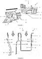
- the ventilation system of Figures 1 and 2 comprises a housing 10 and a flow distributor 20.
- the housing 10 comprises an upper inlet 11 or upstream for admitting air within the ventilation system, for example from ventilation, heating or air conditioning elements. as indicated by the two upper arrows of the Figure 2 .
- the casing 10 further comprises two lower outlets 12 and 13 or downstream intended to expel air towards the flow distributor 20.
- the casing 10 finally comprises two slides 14 intended to assemble the casing 10 to the flow divider 20.
- the flow distributor 20 comprises an upper inlet 21 intended to admit air coming from the housing 10 as well as two lower outlets 22 and 23 intended to be connected to ventilation nozzles in order to expel air towards the interior of a vehicle.
- the flow distributor 20 finally comprises in its upper part two gutters 24 intended to receive the slides 14 of the housing 10.
- the ventilation system 1 is assembled by sliding the flow distributor 20 towards the housing 10 in such a way that the guides 14 of the housing 10 are received in the gutters 24 of the flow distributor 20.
- the assembly by sliding is according to the direction expressed by cross arrows Figures 1 and 2 .
- Line AA 'of the Figure 2 represents the maximum size of the lower outlet 12 to allow the assembly of the ventilation system 1.
- the ventilation system 1 shows two air ducts 2 and 3.
- the air duct 2 must be closed, for example to install the ventilation system 1 in a vehicle requiring few nozzles. ventilation, it is necessary to place a shutter 30 to close the lower outlet 12 of the housing 10, as visible in FIG. Figure 3 .
- this shutter 30 can not be placed beyond the line AA 'visible on the Figure 2 in order not to interfere with the assembly of the ventilation system 1.
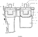
- the housing 10 accommodates movable flaps 40, 45 for regulating the flow of air in each air duct as illustrated in FIGS. Figures 3 to 6 .
- the mobile flap 40 comprises a control shaft 41 as well as closure arms 42, 43.
- the movable flap 40 is capable of adopting a first position in which it is perpendicular to the axis of the air duct 2 and prohibited. the air flow ( Figure 3 ) and a second position in which it is parallel to the axis of the air duct 2 and allow the flow of air in the absence of the shutter 30 ( Figure 4 ).
- the height of the housing 10 is less than the length of the movable flap 40 and the shutter arms 42 and 43 of the movable flap 40 extend beyond the entrance 11 and the air outlet 12 when the movable flap 40 is in the second position visible to the Figure 4 .
- the shutter 30 is at a distance from the control shaft 41 of the movable flap 40 less than half the length of the movable flap 40, or at a distance less than the distance between the shaft for controlling the mobile flap 40 and the end of the movable flap 40 which comes into contact with the wall of the shutter 30.
- the shutter 30 is provided with a wall comprising a flexible portion 31, as visible in FIG. Figure 6 , so that it can be deformed by the movable flap 40, in particular by the closure arm 42. Thanks to this flexible portion 31, the movable flap 40 can reach the second position parallel to the axis of the air duct 2 even when the air duct 2 is closed by the shutter 30.
- the movable flap 45 of the parallel air duct 3 and which shares the same control shaft 41 is not disturbed and can also reach the second position parallel to the axis of the air duct 3 and allow a maximum air flow.
- the flexible portion 31 of the shutter is made of a durable flexible material, such as natural or synthetic elastomers comprising for example rubber, synthetic polyisoprene, polybutadiene or styrene butadiene copolymer.
- the flexible portion 31 may also be made of paper, cardboard or fabric, coated or not.
- the thickness of the flexible portion 31 may be chosen according to the force applied by the movable flap 40 as well as the material. For example, the displacement of the flexible portion 31 during contact with the mobile flap 40 is 0.1 to 1.5 cm.
- the flexible portion 31 can resume its shape when the movable flap moves from the second position to the first position.
- the shutter 30 is substantially sealed. This means that the air flow in the air duct 2 closed by the shutter 30 is reduced by at least 95%, preferably at least 99%.
- a shutter 130 according to a second embodiment is visible at the Figure 7 and comprises a flexible portion 131 similar to the flexible portion 31 according to the first embodiment, and a frame 132 defining a perimeter of the flexible portion 131.
- the frame 132 may be made of the same material as the flexible portion 131 but of greater thickness.
- the frame 132 may be made of a rigid material, such as a plastic such as polypropylene, polyethylene, acrylonitrile-butadiene-styrene copolymer or any other equivalent polymer.
- the frame 132 may also be made of a metal such as steel or aluminum or a composite material.
- the frame 132 confers a greater resistance to the flexible portion 131 and allows the shutter 130 to be fixed in the ventilation system 1 by gluing, welding, interlocking (clipping) or crushing between the casing 10 and the flow distributor 20.
- the frame 132 may also include fastening means (not visible) such as hooks, pads or nesting legs.
- a shutter 230 according to a third embodiment is visible at the Figure 8 and comprises a wall 231 comprising a flexible portion 231a similar to the flexible walls 31 and 131 of the other embodiments and a rigid portion 231b.
- the rigid portion unlike the flexible portion, is made of a material that is not likely to deform when in contact with the movable flap
- the rigid portion 231 b may be made of a rigid material, such as a plastic such as polypropylene, polyethylene, acrylonitrile-butadiene-styrene copolymer or any other equivalent plastic. It can also be made of metal or composite.
- the shutter 230 comprises a frame 232 defining a perimeter of the flexible portion 231.
- the frame 232 is similar to the frame 132.
- the shutter 230 has a reinforced tear resistance and can be adopted in the case of ventilation system with large diameter air ducts.
- a shutter 330 according to a fourth embodiment is visible at the Figure 9 and comprises a flexible portion 331 similar to the flexible walls 31 and 131 of the other embodiments. It comprises a frame 332 defining a perimeter of the flexible portion 331.
- the frame 332 is similar to the frames 132 and 232 but also comprises attachment means in the form of nesting legs 333, intended to be nested / clipped into the housing 10 of the ventilation system 1.
- the frame 232 further comprises a peripheral seal 334 to improve the sealing of the shutter 230, for example to limit the air flow of at least 95 %, preferably at least 99%.
- a shutter comprising a wall having at least one flexible portion makes it possible to close off an air duct even when the space and manufacturing constraints make it necessary to place it at a limited distance from a movable flap of the ventilation system. ventilation, involving interference with this mobile component.
- a flexible portion of a wall of a shutter does not limit the rotation of the movable flaps, which prevents failures of the flow control system and allow a complete opening of the movable shutters located in unobstructed air ducts and embedded on the same control shaft
Abstract
Obturateur (30, 130, 230, 330) pour un système de ventilation (1) pour véhicule, comprenant une paroi agencée pour obturer un conduit d'air dudit système de ventilation, caractérisé en ce que ladite paroi comprend au moins une portion souple (31, 131, 231 a, 331) agencée pour être déformée lors d'un contact entre la paroi et un volet mobile dudit système de ventilation (1), pour permettre un déplacement complet dudit volet mobile (40).Shutter (30, 130, 230, 330) for a ventilation system (1) for a vehicle, comprising a wall arranged to close off an air duct of said ventilation system, characterized in that said wall comprises at least one flexible portion ( 31, 131, 231a, 331) arranged to be deformed upon contact between the wall and a movable flap of said ventilation system (1), to allow complete displacement of said movable flap (40).
Description
L'invention concerne un obturateur destiné à obturer le conduit d'aération d'un système de ventilation de véhicule.The invention relates to a shutter for closing the ventilation duct of a vehicle ventilation system.
Les constructeurs automobiles proposent des gammes de véhicules très étendues, tous les véhicules étant munis d'un système de ventilation servant à chauffer ou à refroidir l'habitacle. Il était donc nécessaire de développer un système de ventilation adapté pour chaque véhicule, pour tenir compte des contraintes spécifiques en terme de flux d'air, d'encombrement du système de ventilation et d'agencement de l'espace intérieur du véhicule. Ceci rendait nécessaire le développement et le maintien d'un grand nombre de systèmes de ventilation différents, ce qui représentait une perte de ressources importante.Car manufacturers offer extensive ranges of vehicles, all vehicles having a ventilation system to heat or cool the passenger compartment. It was therefore necessary to develop a ventilation system adapted to each vehicle, to take into account the specific constraints in terms of air flow, space requirement of the ventilation system and arrangement of the interior space of the vehicle. This made it necessary to develop and maintain a large number of different ventilation systems, which represented a significant loss of resources.
Une solution à ce problème a consisté à développer des systèmes de ventilation modulables pour différents véhicules, réduisant par là même le nombre de références de systèmes de ventilation nécessaires pour équiper une gamme entière de véhicules.One solution to this problem has been to develop modular ventilation systems for different vehicles, thereby reducing the number of ventilation system references needed to fit a whole range of vehicles.
Le document
Ce système à l'inconvénient d'être volumineux en raison de la distance importante entre le volet mobile de l'installation et l'obturateur obturant le tronçon de raccordement.This system has the disadvantage of being bulky because of the large distance between the movable flap of the installation and the shutter closing the connection section.
Un objet de l'invention est donc de résoudre ce problème, à savoir proposer un obturateur pour un système de ventilation compact, sans pour autant gêner le fonctionnement du volet mobile.An object of the invention is therefore to solve this problem, namely to provide a shutter for a compact ventilation system, without interfering with the operation of the movable flap.
Cet objet est atteint grâce aux caractéristiques de la revendication 1 et des revendications dépendantes.This object is achieved by the features of
Un premier aspect de l'invention concerne un obturateur pour un système de ventilation pour véhicule, comprenant une paroi agencée pour obturer un conduit dudit système de ventilation, caractérisé en ce que ladite paroi comprend au moins une portion souple agencée pour être déformée lors d'un contact entre la paroi et un volet mobile dudit système de ventilation, pour permettre un déplacement complet dudit volet mobile. Cette portion souple permet donc l'ouverture complète d'un volet mobile dans les cas où, du fait de contraintes d'encombrement et de fabrication, il n'est possible de positionner l'obturateur qu'en une position induisant forcément une interférence avec le volet mobile. Le système de ventilation accueillant l'obturateur selon la présente invention est donc plus compact que les systèmes de ventilation de l'état de la technique, puisque l'obturateur peut être placé plus proche du volet mobile. De plus, dans le cas de plusieurs conduits d'air équipés de volets mobiles solidaires d'un même arbre de commande, l'obturation d'un des conduits d'air par un obturateur de la présente invention ne gêne pas la régulation du flux d'air dans les autres conduits d'air.A first aspect of the invention relates to a shutter for a vehicle ventilation system, comprising a wall arranged to close a duct of said ventilation system, characterized in that said wall comprises at least one flexible portion arranged to be deformed during a contact between the wall and a movable flap of said ventilation system, to allow complete displacement of said movable flap. This flexible portion therefore allows the complete opening of a movable flap in cases where, due to space constraints and manufacturing, it is possible to position the shutter in a position necessarily inducing interference with the mobile shutter. The ventilation system accommodating the shutter according to the present invention is therefore more compact than the ventilation systems of the state of the art, since the shutter can be placed closer to the movable flap. In addition, in the case of several air ducts equipped with movable flaps integral with the same control shaft, the closure of one of the air ducts by a shutter of the present invention does not interfere with the flow control of air in the other air ducts.
Avantageusement, ladite au moins une portion souple est, en outre, déformée de façon réversible par le volet mobile dudit système de ventilation. Cette déformation réversible permet à la portion souple d'accepter un grand nombre de contacts avec le volet mobile. Ceci peut être réalisé par un matériau adapté, tel qu'un matériau présentant des propriétés élastiques. Un exemple d'un tel matériau est un élastomère comme le caoutchouc, le polyisoprène synthétique, le polybutadiène ou le copolymère de styrène butadiène.Advantageously, said at least one flexible portion is further deformed reversibly by the movable flap of said ventilation system. This reversible deformation allows the flexible portion to accept a large number of contacts with the movable flap. This can be achieved by a suitable material, such as a material having elastic properties. An example of such a material is an elastomer such as rubber, synthetic polyisoprene, polybutadiene or styrene butadiene copolymer.
Alternativement, ladite au moins une portion souple est déformée de façon irréversible lors du premier contact avec le volet mobile. Puisque ce premier contact est fait après l'assemblage du système de ventilation, une déformation irréversible ne gène pas l'assemblage ou le fonctionnement du système de ventilation. Une telle déformation irréversible de la paroi souple permet d'éviter les contacts ultérieurs entre le volet mobile et l'obturateur, et ainsi d'éviter l'application d'un couple lié à ces contacts au système de commande du volet mobile. Une portion souple capable d'une telle déformation irréversible peut être fabriquée d'un matériau souple apte à la déformation plastique, choisi parmi les polymères, le papier ou le carton.Alternatively, said at least one flexible portion is deformed irreversibly during the first contact with the movable flap. Since this first contact is made after assembly of the ventilation system, a irreversible deformation does not interfere with the assembly or operation of the ventilation system. Such irreversible deformation of the flexible wall makes it possible to avoid subsequent contacts between the mobile flap and the shutter, and thus to avoid the application of a torque linked to these contacts to the control system of the movable flap. A flexible portion capable of such irreversible deformation may be made of a flexible material capable of plastic deformation, selected from polymers, paper or cardboard.
Avantageusement, la paroi de l'obturateur comprend une portion rigide en plus de la portion souple. Cette portion rigide peut être faite d'un même matériau que la portion souple, mais d'une épaisseur plus importante, ou bien d'un matériau rigide. Par exemple, un matériau rigide est un matériau qui n'est pas susceptible de se déformer lorsqu'il est en contact avec le volet mobile. De plus, la portion rigide peut être située autour d'une périphérie de la portion souple. Cette portion rigide contribue à rigidifier la paroi de l'obturateur et ainsi à augmenter la résistance de cette paroi au déchirement.Advantageously, the wall of the shutter comprises a rigid portion in addition to the flexible portion. This rigid portion may be made of the same material as the flexible portion, but of greater thickness, or a rigid material. For example, a rigid material is a material that is not likely to deform when in contact with the movable flap. In addition, the rigid portion may be located around a periphery of the flexible portion. This rigid portion contributes to stiffening the wall of the shutter and thus to increase the resistance of this wall to tearing.
Avantageusement, l'obturateur de la présente invention comprend un cadre définissant une périphérie de la portion souple. Ce cadre contribue à rigidifier la portion souple de la paroi, garantissant ainsi une durabilité plus élevée de l'obturateur du fait d'une meilleure résistance à la déchirure de la paroi souple. De plus, ce cadre permet une attache ou un montage aisé à l'intérieur du conduit d'air, par exemple par collage, soudure, emboitement ou écrasement. De façon préférentielle, le cadre de l'obturateur comprend en outre des moyens d'attache aptes à l'attacher au conduit du système de ventilation. Alternativement ou en combinaison, l'obturateur de la présente invention est étanche à l'air. Ceci signifie que le flux d'air dans le conduit obturé peut être réduit d'au moins 95 %, préférentiellement au moins 99 %. De façon encore préférentielle, ce cadre comprend également un joint d'étanchéité périphérique destiné à assurer une étanchéité encore meilleure avec le conduit d'air.Advantageously, the shutter of the present invention comprises a frame defining a periphery of the flexible portion. This frame helps to stiffen the flexible portion of the wall, thus ensuring a higher durability of the shutter due to a better tear strength of the flexible wall. In addition, this frame allows easy attachment or mounting inside the air duct, for example by gluing, welding, nesting or crushing. Preferably, the frame of the shutter further comprises attachment means adapted to attach to the duct of the ventilation system. Alternatively or in combination, the shutter of the present invention is airtight. This means that the air flow in the closed pipe can be reduced by at least 95%, preferably at least 99%. Still more preferably, this frame also comprises a peripheral seal intended to ensure an even better seal with the air duct.
Un deuxième aspect de la présente invention concerne un système de ventilation comprenant au moins un volet mobile, au moins un conduit d'air et au moins un obturateur comprenant une paroi agencée pour obturer le conduit d'air, la paroi comprenant au moins une portion souple agencée pour être déformée lors d'un contact entre la paroi et le volet mobile pour permettre un déplacement complet du dit volet mobile. Un tel système de ventilation peut être installé à la fois dans un véhicule comportant un grand nombre de bouches d'aération, sans l'obturateur, et dans un véhicule comportant peu de bouches d'aération, avec un ou plusieurs conduits d'air obturés. En effet, un tel système de ventilation peut avoir une construction assez compacte, par exemple en deux parties avec un carter comportant des volets mobiles assemblé sur un répartiteur de flux. De plus, l'obturateur de la présente invention permet de condamner les conduits d'air non utilisés dans certains véhicules sans gêner le fonctionnement des volets mobiles situés dans les conduits d'air utilisés.A second aspect of the present invention relates to a ventilation system comprising at least one movable flap, at least one air duct and at least one shutter comprising a wall arranged to close the air duct, the wall comprising at least a portion flexible arranged to be deformed during a contact between the wall and the movable flap to allow complete movement of said movable flap. Such a ventilation system can be installed both in a vehicle having a large number of air vents, without the shutter, and in a vehicle with few air vents, with one or more air ducts closed. . Indeed, such a ventilation system can have a fairly compact construction, for example in two parts with a housing having movable shutters assembled on a flow splitter. In addition, the shutter of the present invention makes it possible to condemn the air ducts that are not used in certain vehicles without hindering the operation of the movable flaps located in the air ducts used.
Avantageusement, le dit volet mobile est agencé pour se déplacer d'une première position où il n'est pas en contact avec la dite paroi vers une deuxième position où il est en contact avec la dite paroi. Par exemple, la première position peut être une position où le volet mobile interdit un flux d'air dans le conduit d'air et la deuxième position peut être une position où le volet mobile autorise un flux d'air dans le conduit d'air si l'obturateur n'est pas présent. De façon préférentielle, le volet mobile peut autoriser dans sa deuxième position un flux d'air maximal dans le conduit d'air si l'obturateur n'est pas présent.Advantageously, said movable flap is arranged to move from a first position where it is not in contact with said wall to a second position where it is in contact with said wall. For example, the first position may be a position where the movable shutter prevents an air flow in the air duct and the second position may be a position where the movable shutter allows a flow of air in the air duct if the shutter is not present. Preferably, the movable flap can allow in its second position a maximum air flow in the air duct if the shutter is not present.
Avantageusement, la portion souple est déformée par le volet mobile lorsque le di volet mobile est déplacé de la première position à la deuxième position. L'obturateur selon la présente invention peut donc autoriser l'ouverture complète du volet mobile.Advantageously, the flexible portion is deformed by the movable flap when the di movable flap is moved from the first position to the second position. The shutter according to the present invention can therefore authorize the complete opening of the movable flap.
Avantageusement, le système de ventilation selon la présente invention comprend en outre :
- un arbre de commande sur lequel est embarqué le volet mobile,
- un deuxième conduit d'air,
- un deuxième volet mobile agencé pour réguler un flux d'air dans le deuxième conduit d'air,
- a control shaft on which is embedded the movable flap,
- a second air duct,
- a second movable flap arranged to regulate an air flow in the second air duct,
D'autres caractéristiques et avantages de la présente invention apparaîtront plus clairement à la lecture de la description détaillée qui suit d'un mode de réalisation de l'invention donné à titre d'exemple nullement limitatif et illustré par les dessins annexés, dans lesquels :
- la
Figure 1 représente une vue en perspective de l'assemblage d'un système de ventilation selon un exemple de la présente invention ; - la
Figure 2 représente une vue en coupe de face du système de ventilation de lafigure 1 ; - la
Figure 3 représente une vue en coupe latérale d'un système de ventilation comprenant un volet mobile dans une première position et un obturateur ; - la
Figure 4 représente une vue en coupe latérale d'un système de ventilation comprenant un volet mobile dans une seconde position et un obturateur ; - la
Figure 5 représente une vue en coupe d'un système de ventilation comprenant deux volets mobiles dans deux conduits d'air parallèles, un des conduits d'air étant obturé par un obturateur ; - la
Figure 6 représente une vue en coupe d'un système de ventilation selon la présente invention comprenant deux volets mobiles dans deux conduits d'air parallèles, un des conduits d'air étant obturé par un obturateur selon la présente invention ; - la
Figure 7 représente un obturateur selon un premier mode de réalisation de la présente invention ; - la
Figure 8 représente un obturateur selon un deuxième mode de réalisation de la présente invention ; - la
Figure 9 représente un obturateur selon un troisième mode de réalisation de la présente invention.
- the
Figure 1 is a perspective view of the assembly of a ventilation system according to an example of the present invention; - the
Figure 2 represents a front sectional view of the ventilation system of thefigure 1 ; - the
Figure 3 is a side sectional view of a ventilation system comprising a movable flap in a first position and a shutter; - the
Figure 4 is a side sectional view of a ventilation system comprising a movable flap in a second position and a shutter; - the
Figure 5 is a sectional view of a ventilation system comprising two movable flaps in two parallel air ducts, one of the air ducts being closed by a shutter; - the
Figure 6 is a sectional view of a ventilation system according to the present invention comprising two movable flaps in two parallel air ducts, one of the air ducts being closed by a shutter according to the present invention; - the
Figure 7 represents a shutter according to a first embodiment of the present invention; - the
Figure 8 represents a shutter according to a second embodiment of the present invention; - the
Figure 9 represents a shutter according to a third embodiment of the present invention.
Le système de ventilation décrit ci-dessous est prévu pour un emploi dans tout type de véhicule de tourisme ou utilitaire. Sa structure est modulable et peut donc adopter différents modes d'exécution. Ce système de ventilation est prévu pour fonctionner avec les éléments classiques de système de ventilation pour véhicule, notamment des éléments de ventilation, des éléments de filtration, des éléments de chauffage et des éléments de climatisation, qui seront donc omis des figures par soucis de clarté.The ventilation system described below is intended for use in any type of passenger vehicle or utility vehicle. Its structure is flexible and can therefore adopt different modes of execution. This ventilation system is intended to work with conventional elements of vehicle ventilation system, including ventilation elements, filtration elements, heating elements and air conditioning elements, which will be omitted from the figures for the sake of clarity .
Le système de ventilation des
Le répartiteur de flux 20 comprend une entrée supérieure 21 destinée à admettre de l'air en provenance du carter 10 ainsi que deux sorties inférieures 22 et 23 destinées à être connectées à des buses de ventilation afin d'expulser de l'air vers l'habitacle d'un véhicule. Le répartiteur de flux 20 comprend enfin dans sa partie supérieure deux gouttières 24 destinées à recevoir les glissières 14 du carter 10.The
L'assemblage du système de ventilation 1 se fait par coulissement du répartiteur de flux 20 vers le carter 10 de telles sortes que les glissières 14 du carter 10 soient reçues dans les gouttières 24 du répartiteur de flux 20. L'assemblage par coulissement se fait selon la direction exprimée par les flèches transversales des
Une fois assemblé, comme visible à la
Le carter 10 accueille des volets mobiles 40, 45 destinés à réguler le flux d'air dans chaque conduit d'air tel qu'illustré dans les
Afin de résoudre ces problèmes, l'obturateur 30 selon un premier mode de réalisation est muni d'une paroi comprenant une portion souple 31, comme visible à la
La portion souple 31 de l'obturateur est faite d'un matériau souple durable, tel que les élastomères naturels ou synthétiques comprenant par exemple le caoutchouc, le polyisoprène synthétique, le polybutadiène ou le copolymère de styrène butadiène. La portion souple 31 peut être également faite de papier, de carton ou de tissu, enduit ou non. L'épaisseur de la portion souple 31 peut être choisie en fonction de la force appliquée par le volet mobile 40 ainsi que du matériau. Par exemple, le déplacement de la portion souple 31 lors du contact avec le volet mobile 40 est de 0,1 à 1,5 cm.The flexible portion 31 of the shutter is made of a durable flexible material, such as natural or synthetic elastomers comprising for example rubber, synthetic polyisoprene, polybutadiene or styrene butadiene copolymer. The flexible portion 31 may also be made of paper, cardboard or fabric, coated or not. The thickness of the flexible portion 31 may be chosen according to the force applied by the
Enfin, la portion souple 31 peut reprendre sa forme quand le volet mobile passe de la second position à la première position.Finally, the flexible portion 31 can resume its shape when the movable flap moves from the second position to the first position.
De façon préférentielle, l'obturateur 30 est substantiellement étanche. Ceci signifie que le flux d'air dans le conduit d'air 2 obturé par l'obturateur 30 est réduit d'au moins 95 %, préférentiellement au moins 99 %.Preferably, the
Un obturateur 130 selon un deuxième mode de réalisation est visible à la
Un obturateur 230 selon un troisième mode de réalisation est visible à la
Un obturateur 330 selon un quatrième mode de réalisation est visible à la
Un obturateur comprenant une paroi ayant au moins une portion souple selon la présente invention permet d'obturer un conduit d'air même quand les contraintes d'encombrement et de fabrication obligent à le placer à une distance limitée d'un volet mobile du système de ventilation, impliquant une interférence avec ce volet mobile. Par son aptitude à se déformer et à revenir à sa place, une portion souple d'une paroi d'un obturateur ne limite pas la rotation des volets mobiles, ce qui permet de prévenir des défaillances du système de contrôle de flux ainsi qu'autoriser une ouverture complète des volets mobiles situés dans les conduits d'air non obstrués et embarqués sur un même arbre de commandeA shutter comprising a wall having at least one flexible portion according to the present invention makes it possible to close off an air duct even when the space and manufacturing constraints make it necessary to place it at a limited distance from a movable flap of the ventilation system. ventilation, involving interference with this mobile component. By its ability to deform and return to its place, a flexible portion of a wall of a shutter does not limit the rotation of the movable flaps, which prevents failures of the flow control system and allow a complete opening of the movable shutters located in unobstructed air ducts and embedded on the same control shaft
On comprendra que diverses modifications et/ou améliorations évidentes pour l'homme du métier peuvent être apportées aux différents modes de réalisation de l'invention décrits dans la présente description sans sortir du cadre de l'invention défini par les revendications annexées. En particulier, il est fait référence aux types de volet mobile, aux différentes configurations possibles de système de ventilation ainsi qu'aux attaches de l'obturateur. En particulier, l'invention n'est pas limitée aux systèmes de ventilation comprenant un carter emboité sur un répartiteur de flux mais s'applique à tout type de système de ventilation.It will be understood that various modifications and / or improvements obvious to those skilled in the art can be made to the various embodiments of the invention described in the present description without departing from the scope of the invention defined by the appended claims. In particular, reference is made to the types of movable flap, to the different possible configurations of ventilation system as well as to the fasteners of the shutter. In particular, the invention is not limited to ventilation comprising a casing fitted on a flow distributor but applies to any type of ventilation system.
Claims (10)
Applications Claiming Priority (1)
| Application Number | Priority Date | Filing Date | Title |
|---|---|---|---|
| FR1651260A FR3047696B1 (en) | 2016-02-17 | 2016-02-17 | SHUTTER FOR AIR VENTILATION SYSTEM FOR VEHICLE |
Publications (1)
| Publication Number | Publication Date |
|---|---|
| EP3208121A1 true EP3208121A1 (en) | 2017-08-23 |
Family
ID=55486980
Family Applications (1)
| Application Number | Title | Priority Date | Filing Date |
|---|---|---|---|
| EP17154874.6A Withdrawn EP3208121A1 (en) | 2016-02-17 | 2017-02-06 | Air ventilation system for a vehicle with a shutter |
Country Status (2)
| Country | Link |
|---|---|
| EP (1) | EP3208121A1 (en) |
| FR (1) | FR3047696B1 (en) |
Citations (5)
| Publication number | Priority date | Publication date | Assignee | Title |
|---|---|---|---|---|
| JP2001105832A (en) * | 1999-10-13 | 2001-04-17 | Mitsubishi Heavy Ind Ltd | Vehicular air conditioner |
| FR2813560A1 (en) | 2000-08-01 | 2002-03-08 | Behr Gmbh & Co | HEATING AND AIR CONDITIONING SYSTEM FOR A MOTOR VEHICLE |
| US20040185765A1 (en) * | 2003-03-07 | 2004-09-23 | Hidehiko Yamaguchi | Air conditioner for vehicle with noise-reduction means |
| JP2004306743A (en) * | 2003-04-04 | 2004-11-04 | Denso Corp | Air conditioning device for vehicle |
| DE102012208935A1 (en) * | 2012-05-29 | 2013-12-05 | Eberspächer Climate Control Systems GmbH & Co. KG | Flow damming element for damming airflow in air duct system of vehicle, has damming element carrier attached at flow guide passages, and damming parts attached at and released from element carrier for changing damming cross-sectional area |
-
2016
- 2016-02-17 FR FR1651260A patent/FR3047696B1/en not_active Expired - Fee Related
-
2017
- 2017-02-06 EP EP17154874.6A patent/EP3208121A1/en not_active Withdrawn
Patent Citations (5)
| Publication number | Priority date | Publication date | Assignee | Title |
|---|---|---|---|---|
| JP2001105832A (en) * | 1999-10-13 | 2001-04-17 | Mitsubishi Heavy Ind Ltd | Vehicular air conditioner |
| FR2813560A1 (en) | 2000-08-01 | 2002-03-08 | Behr Gmbh & Co | HEATING AND AIR CONDITIONING SYSTEM FOR A MOTOR VEHICLE |
| US20040185765A1 (en) * | 2003-03-07 | 2004-09-23 | Hidehiko Yamaguchi | Air conditioner for vehicle with noise-reduction means |
| JP2004306743A (en) * | 2003-04-04 | 2004-11-04 | Denso Corp | Air conditioning device for vehicle |
| DE102012208935A1 (en) * | 2012-05-29 | 2013-12-05 | Eberspächer Climate Control Systems GmbH & Co. KG | Flow damming element for damming airflow in air duct system of vehicle, has damming element carrier attached at flow guide passages, and damming parts attached at and released from element carrier for changing damming cross-sectional area |
Also Published As
| Publication number | Publication date |
|---|---|
| FR3047696A1 (en) | 2017-08-18 |
| FR3047696B1 (en) | 2019-05-03 |
Similar Documents
| Publication | Publication Date | Title |
|---|---|---|
| EP3109084B1 (en) | Front panel module comprising a device for sealing an air inlet | |
| FR3026993A1 (en) | AIR CONTROL DEVICE FOR CONTROLLING AN AIR FLOW IN A VEHICLE | |
| EP1814752A1 (en) | Ventilator flap for a ventilation system in a vehicle cabin | |
| FR2992590A1 (en) | FRONT FACE AIR ENTRY SHUTTERING DEVICE OF MOTOR VEHICLE | |
| FR2956065A1 (en) | AIR EXIT DEVICE FOR AUTOMOTIVE VEHICLE DASHBOARD | |
| WO2009081061A2 (en) | Aerator for automobile passenger compartment and dashboard with such aerator | |
| FR2933036A1 (en) | DEVICE FOR MANEUVERING AN AIR SHUTTING MEANS FOR A HEATING, VENTILATION AND / OR AIR CONDITIONING INSTALLATION, IN PARTICULAR A VEHICLE HABITACLE | |
| EP3208121A1 (en) | Air ventilation system for a vehicle with a shutter | |
| EP0500421A1 (en) | Control valve with an obstructing membrane deformable in the direction of the flow | |
| WO2020174146A1 (en) | Heating and/or ventilation and/or air conditioning system comprising a mixing flap with deflector | |
| WO2016198303A1 (en) | Closure flap and closure device in particular for a front surface air inlet of a motor vehicle and front surface module | |
| EP3576971B1 (en) | Regulating device of an air flow streaming under the hood of a vehicle | |
| WO2012069741A1 (en) | Air-distributing device comprising air guide vanes having complementary deformations that form a seal | |
| EP1749682A1 (en) | Air nozzle, in particular for a vehicle, with pivotable air guiding louvers mounted on a rotatable body | |
| EP1613523B1 (en) | Sealing piece for a hole formed in a wall | |
| EP1818197B1 (en) | Air extractor for an automobile | |
| EP3599404A1 (en) | Adjustable attachment support for installing a tubular item on an external member | |
| EP3411256B1 (en) | Closure device for an air inlet in the front face of a motor vehicle | |
| WO2019170985A1 (en) | Lever for a motor vehicle shut-off device | |
| FR2990261A1 (en) | BONDING UNIT FOR FASTENING A DRIVE TO A COMPONENT, IN PARTICULAR FOR FIXING A HIGH PRESSURE DRIVE IN A CLUTCH SYSTEM OF A MOTOR VEHICLE | |
| FR2633221A1 (en) | DEVICE FOR AERATING AND / OR HEATING THE INTERIOR SPACE OF MOTOR VEHICLES | |
| WO2013050685A1 (en) | Vehicle wheel comprising a cover, and corresponding cover | |
| EP3315335A1 (en) | Vehicle air-conditioning/heating device | |
| EP1695848A1 (en) | Air intake housing for a vehicle heating and/or air conditioning system | |
| FR2845946A1 (en) | Motor vehicle heating, ventilation/air conditioning system has regulator made from two halves with gap between inner and outer walls |
Legal Events
| Date | Code | Title | Description |
|---|---|---|---|
| PUAI | Public reference made under article 153(3) epc to a published international application that has entered the european phase |
Free format text: ORIGINAL CODE: 0009012 |
|
| AK | Designated contracting states |
Kind code of ref document: A1 Designated state(s): AL AT BE BG CH CY CZ DE DK EE ES FI FR GB GR HR HU IE IS IT LI LT LU LV MC MK MT NL NO PL PT RO RS SE SI SK SM TR |
|
| AX | Request for extension of the european patent |
Extension state: BA ME |
|
| RAP1 | Party data changed (applicant data changed or rights of an application transferred) |
Owner name: PSA AUTOMOBILES SA |
|
| 17P | Request for examination filed |
Effective date: 20180214 |
|
| RBV | Designated contracting states (corrected) |
Designated state(s): AL AT BE BG CH CY CZ DE DK EE ES FI FR GB GR HR HU IE IS IT LI LT LU LV MC MK MT NL NO PL PT RO RS SE SI SK SM TR |
|
| GRAP | Despatch of communication of intention to grant a patent |
Free format text: ORIGINAL CODE: EPIDOSNIGR1 |
|
| INTG | Intention to grant announced |
Effective date: 20200217 |
|
| STAA | Information on the status of an ep patent application or granted ep patent |
Free format text: STATUS: THE APPLICATION IS DEEMED TO BE WITHDRAWN |
|
| RAP1 | Party data changed (applicant data changed or rights of an application transferred) |
Owner name: PSA AUTOMOBILES SA |
|
| 18D | Application deemed to be withdrawn |
Effective date: 20200630 |