EP3207319B1 - Kühlschrank - Google Patents
Kühlschrank Download PDFInfo
- Publication number
- EP3207319B1 EP3207319B1 EP15850110.6A EP15850110A EP3207319B1 EP 3207319 B1 EP3207319 B1 EP 3207319B1 EP 15850110 A EP15850110 A EP 15850110A EP 3207319 B1 EP3207319 B1 EP 3207319B1
- Authority
- EP
- European Patent Office
- Prior art keywords
- door
- shelf
- moving part
- rotates
- refrigerator according
- Prior art date
- Legal status (The legal status is an assumption and is not a legal conclusion. Google has not performed a legal analysis and makes no representation as to the accuracy of the status listed.)
- Active
Links
- 238000003860 storage Methods 0.000 claims description 43
- 230000000903 blocking effect Effects 0.000 description 14
- 238000000034 method Methods 0.000 description 5
- 235000013361 beverage Nutrition 0.000 description 4
- 230000004308 accommodation Effects 0.000 description 3
- 230000002452 interceptive effect Effects 0.000 description 2
- 239000000463 material Substances 0.000 description 2
- 239000003507 refrigerant Substances 0.000 description 2
- 235000005911 diet Nutrition 0.000 description 1
- 230000000378 dietary effect Effects 0.000 description 1
- 230000000694 effects Effects 0.000 description 1
- 230000014759 maintenance of location Effects 0.000 description 1
- 229920001296 polysiloxane Polymers 0.000 description 1
- 238000005057 refrigeration Methods 0.000 description 1
Images


Classifications
-
- F—MECHANICAL ENGINEERING; LIGHTING; HEATING; WEAPONS; BLASTING
- F25—REFRIGERATION OR COOLING; COMBINED HEATING AND REFRIGERATION SYSTEMS; HEAT PUMP SYSTEMS; MANUFACTURE OR STORAGE OF ICE; LIQUEFACTION SOLIDIFICATION OF GASES
- F25D—REFRIGERATORS; COLD ROOMS; ICE-BOXES; COOLING OR FREEZING APPARATUS NOT OTHERWISE PROVIDED FOR
- F25D25/00—Charging, supporting, and discharging the articles to be cooled
- F25D25/02—Charging, supporting, and discharging the articles to be cooled by shelves
- F25D25/027—Rotatable shelves
-
- F—MECHANICAL ENGINEERING; LIGHTING; HEATING; WEAPONS; BLASTING
- F25—REFRIGERATION OR COOLING; COMBINED HEATING AND REFRIGERATION SYSTEMS; HEAT PUMP SYSTEMS; MANUFACTURE OR STORAGE OF ICE; LIQUEFACTION SOLIDIFICATION OF GASES
- F25D—REFRIGERATORS; COLD ROOMS; ICE-BOXES; COOLING OR FREEZING APPARATUS NOT OTHERWISE PROVIDED FOR
- F25D23/00—General constructional features
- F25D23/02—Doors; Covers
- F25D23/025—Secondary closures
-
- F—MECHANICAL ENGINEERING; LIGHTING; HEATING; WEAPONS; BLASTING
- F25—REFRIGERATION OR COOLING; COMBINED HEATING AND REFRIGERATION SYSTEMS; HEAT PUMP SYSTEMS; MANUFACTURE OR STORAGE OF ICE; LIQUEFACTION SOLIDIFICATION OF GASES
- F25D—REFRIGERATORS; COLD ROOMS; ICE-BOXES; COOLING OR FREEZING APPARATUS NOT OTHERWISE PROVIDED FOR
- F25D23/00—General constructional features
- F25D23/02—Doors; Covers
- F25D23/04—Doors; Covers with special compartments, e.g. butter conditioners
-
- F—MECHANICAL ENGINEERING; LIGHTING; HEATING; WEAPONS; BLASTING
- F25—REFRIGERATION OR COOLING; COMBINED HEATING AND REFRIGERATION SYSTEMS; HEAT PUMP SYSTEMS; MANUFACTURE OR STORAGE OF ICE; LIQUEFACTION SOLIDIFICATION OF GASES
- F25D—REFRIGERATORS; COLD ROOMS; ICE-BOXES; COOLING OR FREEZING APPARATUS NOT OTHERWISE PROVIDED FOR
- F25D2323/00—General constructional features not provided for in other groups of this subclass
- F25D2323/02—Details of doors or covers not otherwise covered
- F25D2323/023—Door in door constructions
Definitions
- the present invention relates to a refrigerator.
- a refrigerator is an apparatus which has a predetermined accommodation space to maintain food, etc. at low temperature, and divides a low-temperature range into a refrigerator compartment maintained at a temperature above zero (Celsius) and a freezer compartment maintained at a temperature below zero.
- the refrigerator uses cold air generated through heat exchange with a refrigerant circulating according to a refrigeration cycle to cool the refrigerator compartment or the freezer compartment.
- a storage space capable of storing food, and a home bar door capable of withdrawing the food stored in the storage space without opening the door of the refrigerant may be disposed.
- a refrigerator having a foldable shelf which is capable of loading withdrawn food when the food stored in the refrigerator compartment or freezer compartment is withdrawn while the door of the refrigerator is opened is being launched.
- the shelf moves at the same time when the home bar door moves, causing a beverage container, etc. on the shelf to fall.
- US 2013/081423 A1 discloses a refrigerator according to the preamble of claim 1.
- the present invention is suggested to improve the above problem.
- a refrigerator according to the invention is defined in claim 1.
- a refrigerator according to the present invention can prevent a shelf from moving by a second door after the second door opens an accommodation space.
- unfolding the shelf and opening the second door can occur simultaneously and automatically when a user presses the second door once.
- the shelf can be folded toward the accommodation space at the same time.
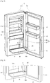
- FIG. 1 is a perspective view of a refrigerator according to an embodiment of the present invention
- FIG. 2 is a partial perspective view of a state in which a door of a refrigerator compartment of a refrigerator in FIG. 1 is open
- FIG. 3 is a perspective view of a state in which a second door is opened at a first door of the refrigerator in FIG. 1 .
- a refrigerator 10 according to an embodiment of the present invention includes a cabinet 20 and a door 30.
- storage spaces 20a and 20b in which food, etc. are stored is formed.
- the storages spaces 20a and 20b may be defined as a refrigerator compartment 20a and a freezer compartment 20b, and the refrigerator compartment 20a and the freezer compartment 20b may be vertically disposed.
- the door 30 may include a refrigerator compartment door 31 for covering the refrigerator compartment 20a, and a freezer compartment door 32 for covering the freezer compartment 20b.
- a storage module 45 may be installed at the refrigerator compartment door 31, and a separate storage space 31a divided from the refrigerator compartment 20a may be formed in the storage module 45.
- a plurality of baskets 46 may be disposed in the shape of a pocket in the storage module 45, and a beverage container, or food, etc. may be stored therein.
- the storage space 31a may be opened toward the outside separately from the refrigerator compartment 20a.
- the refrigerator compartment door 31 includes a first door 311 for opening or closing the refrigerator compartment 20a, and a second door 312 for opening or closing the storage space 31a. Also, the second door 312 may be opened to open the storage space 31a when the refrigerator compartment 20a is closed by the first door 311.
- a blocking door 47 for separating the refrigerator compartment 20a from the storage space 31a may be disposed at the storage module 45.
- the blocking door 47 may be rotatably installed at the storage module 45 to selectively open the storage space 31a toward the refrigerator compartment 20a. Since the blocking door 47 separates the refrigerator compartment 20a from the storage space 31a while the first door 311 is closed and the storage space 31a is opened toward the outside by the second door 312, cold air in the refrigerator compartment 20a may be prevented from leaking to the outside through the storage space 31a.
- the first door 311 may be rotatably connected to the cabinet 20 by a door hinge 33 installed at upper and lower ends of an edge of one side thereof. Consequently, the refrigerator compartment 20a may be opened or closed in accordance with rotation of the first door 311.
- a first sealer 71 may surround an edge of a rear surface of the first door 311 and come in contact with an edge of a front surface of the cabinet 20 when the first door 311 is closed to prevent the leakage of cold air.
- the first sealer 71 is formed of a material which is elastically deformable to be compressible.
- a magnet is disposed inside the first sealer 71 to enable the first sealer 71 to come in close contact with the front surface of the cabinet 20 by a magnetic force.
- the blocking door 47 may also rotate and open the storage space 31a. Consequently, a user may open the refrigerator compartment 20a and the storage space 31a at the same time.
- a first locking unit 61 may be disposed at the blocking door 47 and the storage module 45 to maintain a state in which the blocking door 47 is closed toward the storage module 45.
- the first locking unit 61 may include a first latch hook 62 and a first latch slot 63.
- the first locking unit 61 may enable the first latch hook 62 to be locked to or unlocked from the first latch slot 63 by a user?s manipulation of pressing and releasing the blocking door 47.
- the first latch hook 62 when the user closes the blocking door 47 while the blocking door 47 is open, the first latch hook 62 is inserted into the first latch slot 63 and the blocking door 47 remains closed. In addition, when the user presses and releases the blocking door 47 while the blocking door 47 is closed, the first latch hook 62 is detached from the first latch slot 63 and the blocking door 47 is opened.
- an elastic member such as a torsion spring (not shown) is wound around a hinge which becomes a rotary shaft of the blocking door 47 to enable the first latch hook 62 to automatically rotate by an elastic force of the elastic member and the storage space 31a to be opened when the first latch hook 62 is detached from the first latch slot 63.
- one or more door baskets 48 may be mounted on a rear surface of the second door 312, and the one or more door baskets 48 are accommodated in the storage space 31a while the second door 312 comes in close contact with the first door 311, i.e., while the second door 312 is closed.
- the one or more door baskets 48 may accommodate food, etc., and be disposed between the baskets 46 of the storage space 31a when the second door 312 is closed.
- the one or more door baskets 48 may be disposed between vertically adjacent two baskets 46.
- a front-rear directional width of the one or more door baskets 48 may be designed as a length in which rear surfaces of the one or more door baskets 48 remain spaced apart from the front surfaces of the baskets 46 when the second door 312 is closed. Then, it is fine even if the one or more door baskets 48 and the baskets 46 are disposed at the same height, and a number of mountable door baskets 48 increases.
- a second sealer 72 may surround an edge of the rear surface of the second door 312 to enable the second door 312 to come in contact with an edge of a front surface of the first door 311 when the second door 312 is closed. Similar to the first sealer 71, the second sealer 72 may be formed of a material such as rubber or silicone which is elastically deformable to be compressible. The second sealer 72 comes in close contact with the front surface of the first door 311 while the second door 312 is closed to prevent cold air in the storage space 31a from leaking to the outside through the second door 312.
- a second locking unit 65 may be disposed between the second door 312 and the first door 311 to maintain a state in which the second door 312 is closed toward the first door 311.
- the second locking unit 65 may include a second latch hook 66 and a second latch slot 67.
- the second locking unit 65 may enable the second latch hook 66 to be locked to or unlocked from the second latch slot 67 by a user?s manipulation of pressing and releasing a front surface of the second door 312. Since a configuration and function of the second locking unit 65 are the same as those of the first locking unit 61, an overlapping description with regard to the operation of the first locking unit 61 will be omitted.
- the refrigerator 10 includes a shelf 40 rotatably mounted on the first door 311.
- the shelf 40 may rotate toward the outside (or front) of the storage space 31a while having a horizontal axis as a center of rotation and maintain a horizontally unfolded state. In this state, food or a beverage container, etc. may be placed on an upper surface of the shelf 40.
- the shelf 40 is mounted on the first door 311 to be rotatable toward the outside of the storage space 31a, remains folded while the second door 312 is closed, but rotates toward the outside of the storage space 31a and is unfolded when the second door 312 is opened.
- operations of the shelf 40 and the second door 312 may be interlocked with each other.
- the interlocking between the operation of the shelf 40 and the operation of the second door 312 may be performed by a connection module 50 to be described below.
- the shelf 40 may be mounted on a lower side of the first door 311, i.e., a lower end portion of the storage space 31a, to enable a user to easily put a beverage container, etc. thereon.
- one corner 40a of the shelf 40 may be rounded in a predetermined curvature to prevent the shelf 40 from interfering with the rear surface of the second door 312 when the second door 312 is opened.
- FIGS. 4 to 6 are views illustrating a process in which a shelf is folded when the second door in FIG. 3 is closed toward the first door
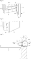
- FIG. 7 is a cross-sectional view taken across line A-A in FIG. 3
- FIGS. 8 and 9 are views illustrating an operational relation between a connection module and shelf in FIG. 7 .
- the refrigerator 10 includes the connection module 50.
- connection module 50 selectively connects the second door 312 to a rotary shaft 41 of the shelf 40. Consequently, when the second door 312 rotates in a direction of opening the storage space 31a, the shelf 40 rotates toward the front of the refrigerator 10 and is horizontally unfolded. Also, when the second door 312 rotates in a direction of closing the storage space 31a, the shelf 40 rotates upward and is vertically folded by the connection module 50.
- the connection module 50 is mounted in the first door 311 and includes a moving part 51 and a connection part 52.
- the moving part 51 is installed such that a front surface 511 thereof is horizontally movable toward the inside and outside of the first door 311.
- a guide hole 311a for guiding the moving part 51 to be slidable is formed at one side of the first door 311, and the front surface 511 of the moving part 51 is able to move toward the inside and outside of the first door 311 in accordance with the guide hole 311a.
- the moving part 51 is installed in the first door 311 to be slidable in front and rear directions of the refrigerator 10.
- a slot 51a into which a bent end 522 of the connection part 52 is inserted is formed in the moving part 51.
- the slot 51a is vertically formed in a predetermined length, and may enable the bent end 522 of the connection part 52 to vertically move when the connection part 52 rotates.
- a length of the slot 51a may be formed in a length corresponding to a vertical distance connecting a point when the shelf 40 is horizontal to a point when the shelf 40 is vertical.
- connection part 52 An extending end 521 of the connection part 52 is fixed to the rotary shaft 41 of the shelf 40, and the bent end 522 is fitted into the slot 51a of the moving part 51.
- the extending end 521 extends from the rotary shaft 41 in a direction perpendicular to the rotary shaft 41.
- the bent end 522 may be bent 90? at an end portion of the extending end 521 such that the connection part 52 is formed in an L-shape.
- the bent end 522 rotates along an arc-shaped trajectory having a length of the extending end 521 as a radius of curvature and the rotary shaft 41 as the center. In other words, when the connection part 52 rotates, an end portion of the bent end 522 vertically moves along the slot 51a.
- the front surface 511 of the moving part 51 which is exposed to the outside of the guide hole 311a is pressed by a pressing protrusion 80 which protrudes from an edge of the rear surface of the second door 312 and inserted into the guide hole 311a.
- the bent end 522 of the connection part 52 rotates while moving from a lower end to an upper end of the slot 51a when the slot 51a horizontally moves backward.
- the extending end 521 of the connection part 52 rotates the rotary shaft 41 of the shelf 40, thereby the shelf 40 is folded after rotating from a horizontal state to a vertical state.
- the moving part 51 rotates the connection part 52 in the opposite direction while moving forward, and the rotary shaft 41 of the shelf 40 also rotates as the connection part 52 rotates, thereby the shelf 40 is unfolded in the horizontal state from the vertical state.
- the bent end 522 rotates while moving from the upper end to the lower end of the slot 51a.
- the extending end 521 and the rotary shaft 41 rotate together as the bent end 522 rotates, thereby the shelf 40 is unfolded in the horizontal state from the vertical state.
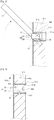
- FIGS. 10 and 11 are views illustrating an operational relation between a shelf and connection module installed at the first door of the refrigerator in FIG. 1 , and a pressing protrusion installed at the second door of the refrigerator in FIG. 1 .
- the pressing protrusion 80 protrudes from the rear surface of the second door 312, and is designed to press the front surface 511 of the moving part 51.
- the pressing protrusion 80 may be a part of the second door 312, or a separate independent member may be provided by being coupled to the second door 312.
- a pressing surface of the pressing protrusion 80 is formed in a gently rounded shape to prevent the front surface 511 of the moving part 51 from being damaged, and enable the moving part 51 to smoothly move in a horizontal direction.
- a force of the moving part 51 pushing the pressing protrusion 80 may be dispersed throughout the pressing protrusion 80, and noise generated as the pressing surface 81 slides while coming in contact with the front surface 511 of the moving part 51 may be reduced.
- an elastic member 53 exerting a force pushing the moving part 51 forward is mounted on a rear surface of the moving part 51.
- the elastic member 53 is not shown in FIGS. 7 and 8 , the elastic member 53 is mounted on a structure.
- the elastic member 53 remains reduced when the second door 312 is closed, i.e., when the shelf 40 is folded, and as the elastic member 53 rotates in a direction in which the second door 312 is opened, the elastic member 53 pushes the moving part 51 forward while being stretched by a restoration force. As a result, the front surface 511 of the moving part 51 always comes in contact with the pressing surface 81 of the pressing protrusion 80 and presses the pressing surface 81.
- rotation sections R1 and R2 in which the second door 312 rotates may be divided into a first rotation section R1 and a second rotation section R2.
- the first rotation section R1 is a section in which the second door 312 comes in contact with the connection module 50. Consequently, when the second door 312 moves in the first rotation section R1, the pressing surface 81 of the pressing protrusion 80 may come in contact with the front surface 511 of the moving part 51, and the shelf 40 may be folded or unfolded.
- the second rotation section R2 is a section in which the second door 312 is spaced apart from the connection module 50. Even when the second door 312 moves in the second rotation section R2, the shelf 40 is able to maintain a horizontal state since the pressing surface 81 of the pressing protrusion 80 is spaced apart from the front surface 511 of the moving part 51.
- the shelf 40 may form a predetermined angle from a vertical surface 41a passing along the rotary shaft of the shelf 40 while completely folded.
- a center of mass of the shelf 40 may be formed in front of the vertical surface 41a to generate a torque caused by a load of the shelf 40 while the shelf 40 is completely folded.
- a separate elastic member 53 does not have to be mounted behind the moving part 51.
- an elastic member such as a torsion spring may be mounted on the rotary shaft of the shelf 40.
- a restoration force of the torsion spring may act in a direction enabling the shelf 40 to rotate forward when folded. Then, the rotary shaft 41 of the shelf 40 rotates by the restoration force of the torsion spring when the second door 312 is opened, and the moving part 51 will move forward as a result.
- the moving part 51 may further include a stopper 512.
- the stopper 512 may be disposed at the moving part 51, and may come in contact with a contact member 311b formed in the guide hole 311a of the first door 311 and limit rotation of the shelf 40 while the shelf 40 is unfolded toward the outside and in a horizontal state.
- a limiting protrusion may protrude from one side of an inner circumferential surface of the guide hole 311a and an outer circumferential surface of the moving part 51, and a limiting groove which accommodates the limiting protrusion to limit a moving distance of the limiting protrusion may be formed at the other side thereof.
- the refrigerator 10 may further include a damper (not shown).
- the damper (not shown) may be disposed at one of the stopper 512 and the contact member 311b, and mitigate a contact impact when the stopper 512 comes in contact with the contact member 311b.
- a connection module may include a pinion gear installed at the rotary shaft 41 of the shelf 40, and a rack gear installed at the first door 311 to be movable toward the inside and outside of the first door 311, and engaged with the pinion gear to rotate the pinion gear.
- a front surface of the rack gear comes in close contact with the pressing surface 81 of the pressing protrusion 80, causing the rack gear to move forward and backward in accordance with a direction in which the second door 312 rotates.
- the pressing protrusion 80 installed at the rear surface of the second door 312 continues to press the moving part 51.
- the second door 312 is unlocked from the second locking unit 65 when a front surface of the second door 312 is pressed and released, causing the second door 312 to open the storage space 31a while rotating.
- the shelf 40 rotates forward and is horizontally unfolded by the restoration force of the elastic member 53 or an eccentric center of mass of the shelf 40.
- the bent end 522 of the connection part 52 pushes the front surface 511 of the moving part 51 toward the outside of the guide hole 311a while rotating when the rotary shaft 41 of the shelf 40 rotates.
- the front surface 511 of the moving part 51 presses the pressing protrusion 80 formed at the rear surface of the second door 312 and facilitates opening of the second door 312.
- the second door 312 When the shelf 40 is unfolded, the second door 312 is positioned in the second rotation section R2. In addition, when the second door 312 rotates in the closing direction by a user, the second door 312 enters the first rotation section R1.
- the pressing protrusion 80 comes in contact with the front surface 511 of the moving part 51 when the second door 312 enters the first rotation section R1, and presses the front surface 511 of the moving part 51 in the first rotation section R1.
- connection part 52 When the front surface 511 of the moving part 51 is pressed, the bent end 522 of the connection part 52 moves from the lower end of the slot 51a toward the upper end thereof while rotating by the slot 51a. Since the extending end 521 of the connection part 52 is fixed and connected to the rotary shaft 41 of the shelf 40, the extending end 521 rotates the rotary shaft 41 of the shelf 40, and the shelf 40 is stood toward the storage space 31a.
- the shelf 40 is folded toward the inside of the storage space 31a at the same time.
Claims (11)
- Kühlschrank aufweisend:ein Gehäuse (20), das konfiguriert ist, einen Aufbewahrungsraum zu bilden;eine erste Tür (311), die mit einer Vorderfläche des Gehäuses drehbar gekoppelt ist, um den Aufbewahrungsraum zu öffnen oder zu schließen, und in der ein offener Abschnitt gebildet ist;eine zweite Tür (312), die mit der ersten Tür an einer Vorderfläche der ersten Tür drehbar verbunden ist;einen Pressvorsprung (80), der konfiguriert ist, um aus einer Rückfläche der zweiten Tür vorzuspringen;ein Paneel (40), das in dem offenen Abschnitt drehbar angebracht ist; undein Verbindungsmodul (50), das in der ersten Tür bereitgestellt ist und mit einer drehenden Welle (41) des Paneels verbunden ist, um zu erlauben, dass das Paneel nach vorn aufklappt, wenn die zweite Tür geöffnet wird, und zusammengeklappt aufrecht steht, wenn die zweite Tür geschlossen ist,wobei das Verbindungsmodul konfiguriert ist, den Pressvorsprung selektiv zu kontaktieren,wobei das Verbindungsmodul aufweist:einen Verbindungsteil (52), der mit der drehenden Welle des Paneels verbunden ist, um sich mit der drehenden Welle des Paneels integral zu drehen;dadurch gekennzeichnet, dass das Verbindungsmodul ferner aufweist:einen Bewegungsteil (51), der mit dem Verbindungsteil verbunden ist und konfiguriert ist, sich innerhalb eines in der ersten Tür gebildeten Führungslochs (311a) vor und zurück zu bewegen, wenn der Verbindungsteil sich dreht,wobei, wenn die zweite Tür geöffnet ist und das Paneel in einem horizontalen Zustand ist, eine Vorderfläche (511) des Bewegungsteils aus dem Führungsloch (311a) herausschaut,wobei, wenn sich die zweite Tür (312) in eine schließende Richtung dreht, die aus dem Führungsloch (311a) herausschauende Vorderfläche (511) des Bewegungsteils (51) von dem Pressvorsprung (80) gepresst wird und sich zurück in das Führungsloch (311a) hinein bewegt,wobei, wenn sich der Bewegungsteil zurück bewegt, sich der Verbindungsteil dreht und sich das Paneel aus dem horizontalen Zustand in einen vertikalen Zustand dreht, undwobei das Verbindungsmodul ein begrenzendes Element aufweist, das an dem Bewegungsteil (51) bzw. dem Führungsloch (311a) gebildet ist, um eine Vorwärtsbewegungsstrecke des Bewegungsteils (51) zu begrenzen.
- Kühlschrank nach Anspruch 1, wobei der Verbindungsteil aufweist:ein verlängertes Ende (521), das konfiguriert ist, sich von der drehenden Welle des Paneels in eine die drehenden Welle des Paneels kreuzende Richtung zu erstrecken; undein gebogenes Ende (522), das an einem Endabschnitt des verlängerten Endes gebogen ist und mit dem Bewegungsteil verbunden ist,wobei ein Schlitz (51a), in den das gebogene Ende eingesetzt ist, in dem Bewegungsteil vertikal gebildet ist, undwobei, wenn sich der Verbindungsteil dreht, das gebogene Ende konfiguriert ist, sich vertikal zu bewegen.
- Kühlschrank nach Anspruch 1 oder 2, wobei eine Pressoberfläche, mit der die Vorderfläche des Bewegungsteils in Kontakt kommt, an dem Pressvorsprung gebildet ist, und wobei die Pressoberfläche in einer gerundeten Form gebildet ist.
- Kühlschrank nach Anspruch 1, wobei ein Drehabschnitt, der sich dreht, um die zweite Tür zu öffnen oder zu schließen, aufweist:einen ersten Drehabschnitt (R1), in dem der Bewegungsteil einen Zustand beibehält, in dem er in engen Kontakt mit dem Pressvorsprung kommt; undeinen zweiten Drehabschnitt (R2), in dem der Bewegungsteil von dem Pressvorsprung getrennt ist.
- Kühlschrank nach Anspruch 1, wobei das begrenzende Element aufweist:ein Kontaktelement (311b), das konfiguriert ist, um von einer Innenumfangsfläche eines vorderen Endabschnitts des Führungslochs vorzustehen; undeinen Stopper (512), der konfiguriert ist, um von einer Außenumfangsfläche des Bewegungsteils vorzustehen, um an dem Kontaktelement gefasst zu werden.
- Kühlschrank nach Anspruch 5, ferner aufweisend einen Dämpfer, der entweder an dem Kontaktelement oder dem Stopper bereitgestellt ist, um einen Aufprall zu mindern, der entsteht, wenn der Stopper in Kontakt mit dem Kontaktelement kommt.
- Kühlschrank nach Anspruch 1, wobei das begrenzende Element aufweist:einen begrenzenden Vorsprung, der konfiguriert ist, um von der einen von Innenumfangsfläche des Führungslochs und Außenumfangsfläche des Bewegungsteils vorzustehen; undeine begrenzende Rille, die in der anderen von Innenumfangsfläche des Führungslochs und Außenumfangsfläche des Bewegungsteils ausgespart ist und konfiguriert ist, sich in einer Länge horizontal zu erstrecken,wobei sich der begrenzende Vorsprung in der begrenzenden Rille bewegt, wenn sich der Bewegungsteil bewegt.
- Kühlschrank nach einem der Ansprüche 5 bis 7, ferner aufweisend ein elastisches Element (53), das hinter dem Bewegungsteil angeordnet ist, um eine Kraft auszuüben, die den Bewegungsteil nach vorn drückt,
wobei, wenn sich die zweite Tür in eine Öffnungsrichtung dreht, der Bewegungsteil sich nach vorn bewegt, bis der Stopper durch die Kraft, die den Bewegungsteil drückt, in Kontakt mit dem Kontaktelement kommt,
wobei sich der Verbindungsteil durch die Vorwärtsbewegung des Bewegungsteils dreht, und wobei durch Drehung des Verbindungsteils das Paneel sich von dem vertikalen Zustand in den horizontalen Zustand dreht. - Kühlschrank nach Anspruch 1, wobei, wenn die zweite Tür in einer geschlossenen Position ist, das Paneel nach vorn in einem Winkel von einer vertikalen Fläche, die sich entlang der drehenden Welle des Paneels erstreckt, beabstandet ist, derart, dass ein Massenzentrum des Paneels vor der vertikalen Fläche angeordnet ist, um ein von einer Last des Paneels bewirktes Drehmoment zu erzeugen,
wobei, wenn sich die zweite Tür in eine Öffnungsrichtung dreht, das Paneel sich durch das Drehmoment in den horizontalen Zustand dreht. - Kühlschrank nach Anspruch 1, wobei der Verbindungsteil ein Zahnrad aufweist, das mit der drehenden Welle des Paneels verbunden ist,
und wobei der Bewegungsteil eine Zahnstange aufweist, die mit dem Zahnrad im Eingriff ist und konfiguriert ist, sich vor und zurück zu bewegen. - Kühlschrank nach Anspruch 10, wobei ein vorderer Endabschnitt der Zahnstange in selektiven Kontakt mit der Rückfläche der zweiten Tür kommt.
Priority Applications (1)
| Application Number | Priority Date | Filing Date | Title |
|---|---|---|---|
| EP20190573.4A EP3770538B1 (de) | 2014-10-17 | 2015-10-19 | Kühlschrank |
Applications Claiming Priority (2)
| Application Number | Priority Date | Filing Date | Title |
|---|---|---|---|
| KR1020140140653A KR101691260B1 (ko) | 2014-10-17 | 2014-10-17 | 냉장고 |
| PCT/KR2015/011036 WO2016060531A1 (en) | 2014-10-17 | 2015-10-19 | Refrigerator |
Related Child Applications (2)
| Application Number | Title | Priority Date | Filing Date |
|---|---|---|---|
| EP20190573.4A Division-Into EP3770538B1 (de) | 2014-10-17 | 2015-10-19 | Kühlschrank |
| EP20190573.4A Division EP3770538B1 (de) | 2014-10-17 | 2015-10-19 | Kühlschrank |
Publications (3)
| Publication Number | Publication Date |
|---|---|
| EP3207319A1 EP3207319A1 (de) | 2017-08-23 |
| EP3207319A4 EP3207319A4 (de) | 2018-05-23 |
| EP3207319B1 true EP3207319B1 (de) | 2020-09-23 |
Family
ID=55746978
Family Applications (2)
| Application Number | Title | Priority Date | Filing Date |
|---|---|---|---|
| EP15850110.6A Active EP3207319B1 (de) | 2014-10-17 | 2015-10-19 | Kühlschrank |
| EP20190573.4A Active EP3770538B1 (de) | 2014-10-17 | 2015-10-19 | Kühlschrank |
Family Applications After (1)
| Application Number | Title | Priority Date | Filing Date |
|---|---|---|---|
| EP20190573.4A Active EP3770538B1 (de) | 2014-10-17 | 2015-10-19 | Kühlschrank |
Country Status (6)
| Country | Link |
|---|---|
| US (1) | US10113789B2 (de) |
| EP (2) | EP3207319B1 (de) |
| KR (1) | KR101691260B1 (de) |
| CN (1) | CN106605115B (de) |
| ES (1) | ES2821824T3 (de) |
| WO (1) | WO2016060531A1 (de) |
Families Citing this family (11)
| Publication number | Priority date | Publication date | Assignee | Title |
|---|---|---|---|---|
| KR101627935B1 (ko) * | 2014-10-22 | 2016-06-07 | 엘지전자 주식회사 | 냉장고 |
| EP3543632B1 (de) | 2015-03-18 | 2021-04-07 | LG Electronics Inc. | Kühlschrank |
| KR102577442B1 (ko) * | 2016-06-07 | 2023-09-11 | 엘지전자 주식회사 | 냉장고 및 이에 구비된 접힘유도장치 |
| CN108253708A (zh) * | 2016-12-29 | 2018-07-06 | 博西华电器(江苏)有限公司 | 家用电器 |
| US10914507B2 (en) * | 2017-06-06 | 2021-02-09 | Whirlpool Corporation | Appliance bin |
| KR102573779B1 (ko) * | 2018-11-20 | 2023-09-04 | 삼성전자주식회사 | 냉장고 |
| CN111664640B (zh) * | 2019-03-05 | 2022-11-11 | Bsh家用电器有限公司 | 具有包括覆盖件的门装置的家用制冷器具 |
| CN112484386A (zh) * | 2019-09-11 | 2021-03-12 | 青岛海尔电冰箱有限公司 | 搁物架及冰箱 |
| US11668513B2 (en) | 2020-12-01 | 2023-06-06 | Electrolux Home Products, Inc. | Staged access door for a home appliance |
| US11215391B1 (en) * | 2020-12-01 | 2022-01-04 | Electrolux Home Products, Inc. | Staged access door for a home appliance |
| CN115839582A (zh) * | 2021-09-18 | 2023-03-24 | 海信(山东)冰箱有限公司 | 冰箱 |
Family Cites Families (15)
| Publication number | Priority date | Publication date | Assignee | Title |
|---|---|---|---|---|
| US2112771A (en) * | 1934-03-30 | 1938-03-29 | Nash Kelvinator Corp | Refrigerating apparatus |
| US2062360A (en) * | 1934-03-30 | 1936-12-01 | Kelvinator Corp | Refrigerating apparatus |
| JPH06103146B2 (ja) * | 1989-11-16 | 1994-12-14 | 三洋電機株式会社 | 冷蔵庫 |
| CN1683854A (zh) * | 2004-04-12 | 2005-10-19 | 乐金电子(天津)电器有限公司 | 冰箱显示器部锁的结构 |
| EP2090214A1 (de) * | 2004-07-23 | 2009-08-19 | BSH Bosch und Siemens Hausgeräte GmbH | Vorrichtung zur Besteckablage in Geschirrspülmaschinen |
| TWM284285U (en) * | 2005-07-13 | 2006-01-01 | Yu Yu Ting | Foldable type multi-function load bearing device |
| US8640482B2 (en) | 2006-08-11 | 2014-02-04 | Samsung Electronics Co., Ltd. | Refrigerator having folding shelf |
| KR101055736B1 (ko) * | 2008-09-30 | 2011-08-11 | 엘지전자 주식회사 | 김치냉장고 |
| KR101307681B1 (ko) * | 2009-06-03 | 2013-09-12 | 엘지전자 주식회사 | 냉장고 |
| KR101704817B1 (ko) | 2010-08-20 | 2017-02-08 | 엘지전자 주식회사 | 냉장고 |
| KR101923471B1 (ko) * | 2011-10-04 | 2018-11-29 | 엘지전자 주식회사 | 냉장고 |
| KR101298070B1 (ko) * | 2011-10-20 | 2013-08-20 | 라현진 | 냉장고용 선반 어셈블리 및 그를 구비한 공간 가변형 냉장고 |
| KR101844072B1 (ko) * | 2011-11-11 | 2018-05-15 | 엘지전자 주식회사 | 냉장고 |
| KR101918296B1 (ko) | 2012-06-21 | 2019-01-29 | 엘지전자 주식회사 | 냉장고 |
| EP3543632B1 (de) * | 2015-03-18 | 2021-04-07 | LG Electronics Inc. | Kühlschrank |
-
2014
- 2014-10-17 KR KR1020140140653A patent/KR101691260B1/ko active IP Right Grant
-
2015
- 2015-10-19 ES ES15850110T patent/ES2821824T3/es active Active
- 2015-10-19 WO PCT/KR2015/011036 patent/WO2016060531A1/en active Application Filing
- 2015-10-19 CN CN201580047043.8A patent/CN106605115B/zh active Active
- 2015-10-19 US US15/516,925 patent/US10113789B2/en active Active
- 2015-10-19 EP EP15850110.6A patent/EP3207319B1/de active Active
- 2015-10-19 EP EP20190573.4A patent/EP3770538B1/de active Active
Non-Patent Citations (1)
| Title |
|---|
| None * |
Also Published As
| Publication number | Publication date |
|---|---|
| EP3207319A1 (de) | 2017-08-23 |
| ES2821824T3 (es) | 2021-04-27 |
| KR101691260B1 (ko) | 2016-12-29 |
| EP3770538B1 (de) | 2022-02-16 |
| CN106605115B (zh) | 2019-07-30 |
| EP3770538A1 (de) | 2021-01-27 |
| EP3207319A4 (de) | 2018-05-23 |
| KR20160045314A (ko) | 2016-04-27 |
| US10113789B2 (en) | 2018-10-30 |
| CN106605115A (zh) | 2017-04-26 |
| WO2016060531A1 (en) | 2016-04-21 |
| US20170299256A1 (en) | 2017-10-19 |
Similar Documents
| Publication | Publication Date | Title |
|---|---|---|
| EP3207319B1 (de) | Kühlschrank | |
| KR102391409B1 (ko) | 냉장고 | |
| US11408668B2 (en) | Refrigerator | |
| EP3333518B1 (de) | Kühlschrank | |
| EP2770285B1 (de) | Kühlschrank | |
| EP2431688B1 (de) | Kühlvorrichtung | |
| EP2594879B1 (de) | Kühlschrank | |
| EP2784417B1 (de) | Begrenzer zum Öffnen einer Kühlschranktür | |
| EP3034973B1 (de) | Kühlschrank | |
| EP3209959B1 (de) | Kühlschrank | |
| KR102567513B1 (ko) | 냉장고 | |
| EP3355010A1 (de) | Kühlschrank | |
| US20120293056A1 (en) | Door basket and refrigerator including same | |
| KR20130036672A (ko) | 냉장고 | |
| KR102059573B1 (ko) | 냉장고 | |
| KR101861368B1 (ko) | 냉장고 | |
| KR20200058700A (ko) | 냉장고 | |
| US10393424B2 (en) | Refrigerator | |
| EP3839390B1 (de) | Kühlschrank | |
| EP3258196A2 (de) | Kühlschrank | |
| KR102093448B1 (ko) | 냉장고 | |
| CN218092595U (zh) | 具有凹口的铰链组件及具有其的制冷设备 | |
| KR20170071039A (ko) | 냉장고 |
Legal Events
| Date | Code | Title | Description |
|---|---|---|---|
| STAA | Information on the status of an ep patent application or granted ep patent |
Free format text: STATUS: THE INTERNATIONAL PUBLICATION HAS BEEN MADE |
|
| PUAI | Public reference made under article 153(3) epc to a published international application that has entered the european phase |
Free format text: ORIGINAL CODE: 0009012 |
|
| STAA | Information on the status of an ep patent application or granted ep patent |
Free format text: STATUS: REQUEST FOR EXAMINATION WAS MADE |
|
| 17P | Request for examination filed |
Effective date: 20170315 |
|
| AK | Designated contracting states |
Kind code of ref document: A1 Designated state(s): AL AT BE BG CH CY CZ DE DK EE ES FI FR GB GR HR HU IE IS IT LI LT LU LV MC MK MT NL NO PL PT RO RS SE SI SK SM TR |
|
| AX | Request for extension of the european patent |
Extension state: BA ME |
|
| DAV | Request for validation of the european patent (deleted) | ||
| DAX | Request for extension of the european patent (deleted) | ||
| A4 | Supplementary search report drawn up and despatched |
Effective date: 20180424 |
|
| RIC1 | Information provided on ipc code assigned before grant |
Ipc: F25D 25/02 20060101AFI20180418BHEP Ipc: F25D 23/02 20060101ALI20180418BHEP |
|
| GRAP | Despatch of communication of intention to grant a patent |
Free format text: ORIGINAL CODE: EPIDOSNIGR1 |
|
| STAA | Information on the status of an ep patent application or granted ep patent |
Free format text: STATUS: GRANT OF PATENT IS INTENDED |
|
| INTG | Intention to grant announced |
Effective date: 20200406 |
|
| GRAS | Grant fee paid |
Free format text: ORIGINAL CODE: EPIDOSNIGR3 |
|
| GRAA | (expected) grant |
Free format text: ORIGINAL CODE: 0009210 |
|
| STAA | Information on the status of an ep patent application or granted ep patent |
Free format text: STATUS: THE PATENT HAS BEEN GRANTED |
|
| AK | Designated contracting states |
Kind code of ref document: B1 Designated state(s): AL AT BE BG CH CY CZ DE DK EE ES FI FR GB GR HR HU IE IS IT LI LT LU LV MC MK MT NL NO PL PT RO RS SE SI SK SM TR |
|
| REG | Reference to a national code |
Ref country code: GB Ref legal event code: FG4D |
|
| REG | Reference to a national code |
Ref country code: CH Ref legal event code: EP |
|
| REG | Reference to a national code |
Ref country code: DE Ref legal event code: R096 Ref document number: 602015059635 Country of ref document: DE |
|
| REG | Reference to a national code |
Ref country code: IE Ref legal event code: FG4D |
|
| REG | Reference to a national code |
Ref country code: AT Ref legal event code: REF Ref document number: 1316808 Country of ref document: AT Kind code of ref document: T Effective date: 20201015 |
|
| PG25 | Lapsed in a contracting state [announced via postgrant information from national office to epo] |
Ref country code: FI Free format text: LAPSE BECAUSE OF FAILURE TO SUBMIT A TRANSLATION OF THE DESCRIPTION OR TO PAY THE FEE WITHIN THE PRESCRIBED TIME-LIMIT Effective date: 20200923 Ref country code: SE Free format text: LAPSE BECAUSE OF FAILURE TO SUBMIT A TRANSLATION OF THE DESCRIPTION OR TO PAY THE FEE WITHIN THE PRESCRIBED TIME-LIMIT Effective date: 20200923 Ref country code: NO Free format text: LAPSE BECAUSE OF FAILURE TO SUBMIT A TRANSLATION OF THE DESCRIPTION OR TO PAY THE FEE WITHIN THE PRESCRIBED TIME-LIMIT Effective date: 20201223 Ref country code: GR Free format text: LAPSE BECAUSE OF FAILURE TO SUBMIT A TRANSLATION OF THE DESCRIPTION OR TO PAY THE FEE WITHIN THE PRESCRIBED TIME-LIMIT Effective date: 20201224 Ref country code: HR Free format text: LAPSE BECAUSE OF FAILURE TO SUBMIT A TRANSLATION OF THE DESCRIPTION OR TO PAY THE FEE WITHIN THE PRESCRIBED TIME-LIMIT Effective date: 20200923 Ref country code: BG Free format text: LAPSE BECAUSE OF FAILURE TO SUBMIT A TRANSLATION OF THE DESCRIPTION OR TO PAY THE FEE WITHIN THE PRESCRIBED TIME-LIMIT Effective date: 20201223 |
|
| REG | Reference to a national code |
Ref country code: AT Ref legal event code: MK05 Ref document number: 1316808 Country of ref document: AT Kind code of ref document: T Effective date: 20200923 |
|
| PG25 | Lapsed in a contracting state [announced via postgrant information from national office to epo] |
Ref country code: LV Free format text: LAPSE BECAUSE OF FAILURE TO SUBMIT A TRANSLATION OF THE DESCRIPTION OR TO PAY THE FEE WITHIN THE PRESCRIBED TIME-LIMIT Effective date: 20200923 Ref country code: RS Free format text: LAPSE BECAUSE OF FAILURE TO SUBMIT A TRANSLATION OF THE DESCRIPTION OR TO PAY THE FEE WITHIN THE PRESCRIBED TIME-LIMIT Effective date: 20200923 |
|
| REG | Reference to a national code |
Ref country code: NL Ref legal event code: MP Effective date: 20200923 |
|
| REG | Reference to a national code |
Ref country code: LT Ref legal event code: MG4D |
|
| REG | Reference to a national code |
Ref country code: ES Ref legal event code: FG2A Ref document number: 2821824 Country of ref document: ES Kind code of ref document: T3 Effective date: 20210427 |
|
| PG25 | Lapsed in a contracting state [announced via postgrant information from national office to epo] |
Ref country code: PT Free format text: LAPSE BECAUSE OF FAILURE TO SUBMIT A TRANSLATION OF THE DESCRIPTION OR TO PAY THE FEE WITHIN THE PRESCRIBED TIME-LIMIT Effective date: 20210125 Ref country code: RO Free format text: LAPSE BECAUSE OF FAILURE TO SUBMIT A TRANSLATION OF THE DESCRIPTION OR TO PAY THE FEE WITHIN THE PRESCRIBED TIME-LIMIT Effective date: 20200923 Ref country code: SM Free format text: LAPSE BECAUSE OF FAILURE TO SUBMIT A TRANSLATION OF THE DESCRIPTION OR TO PAY THE FEE WITHIN THE PRESCRIBED TIME-LIMIT Effective date: 20200923 Ref country code: EE Free format text: LAPSE BECAUSE OF FAILURE TO SUBMIT A TRANSLATION OF THE DESCRIPTION OR TO PAY THE FEE WITHIN THE PRESCRIBED TIME-LIMIT Effective date: 20200923 Ref country code: LT Free format text: LAPSE BECAUSE OF FAILURE TO SUBMIT A TRANSLATION OF THE DESCRIPTION OR TO PAY THE FEE WITHIN THE PRESCRIBED TIME-LIMIT Effective date: 20200923 Ref country code: CZ Free format text: LAPSE BECAUSE OF FAILURE TO SUBMIT A TRANSLATION OF THE DESCRIPTION OR TO PAY THE FEE WITHIN THE PRESCRIBED TIME-LIMIT Effective date: 20200923 |
|
| PG25 | Lapsed in a contracting state [announced via postgrant information from national office to epo] |
Ref country code: AL Free format text: LAPSE BECAUSE OF FAILURE TO SUBMIT A TRANSLATION OF THE DESCRIPTION OR TO PAY THE FEE WITHIN THE PRESCRIBED TIME-LIMIT Effective date: 20200923 Ref country code: AT Free format text: LAPSE BECAUSE OF FAILURE TO SUBMIT A TRANSLATION OF THE DESCRIPTION OR TO PAY THE FEE WITHIN THE PRESCRIBED TIME-LIMIT Effective date: 20200923 Ref country code: PL Free format text: LAPSE BECAUSE OF FAILURE TO SUBMIT A TRANSLATION OF THE DESCRIPTION OR TO PAY THE FEE WITHIN THE PRESCRIBED TIME-LIMIT Effective date: 20200923 Ref country code: IS Free format text: LAPSE BECAUSE OF FAILURE TO SUBMIT A TRANSLATION OF THE DESCRIPTION OR TO PAY THE FEE WITHIN THE PRESCRIBED TIME-LIMIT Effective date: 20210123 |
|
| REG | Reference to a national code |
Ref country code: CH Ref legal event code: PL |
|
| REG | Reference to a national code |
Ref country code: DE Ref legal event code: R097 Ref document number: 602015059635 Country of ref document: DE |
|
| PG25 | Lapsed in a contracting state [announced via postgrant information from national office to epo] |
Ref country code: MC Free format text: LAPSE BECAUSE OF FAILURE TO SUBMIT A TRANSLATION OF THE DESCRIPTION OR TO PAY THE FEE WITHIN THE PRESCRIBED TIME-LIMIT Effective date: 20200923 Ref country code: LU Free format text: LAPSE BECAUSE OF NON-PAYMENT OF DUE FEES Effective date: 20201019 Ref country code: SK Free format text: LAPSE BECAUSE OF FAILURE TO SUBMIT A TRANSLATION OF THE DESCRIPTION OR TO PAY THE FEE WITHIN THE PRESCRIBED TIME-LIMIT Effective date: 20200923 |
|
| REG | Reference to a national code |
Ref country code: BE Ref legal event code: MM Effective date: 20201031 |
|
| PLBE | No opposition filed within time limit |
Free format text: ORIGINAL CODE: 0009261 |
|
| STAA | Information on the status of an ep patent application or granted ep patent |
Free format text: STATUS: NO OPPOSITION FILED WITHIN TIME LIMIT |
|
| PG25 | Lapsed in a contracting state [announced via postgrant information from national office to epo] |
Ref country code: DK Free format text: LAPSE BECAUSE OF FAILURE TO SUBMIT A TRANSLATION OF THE DESCRIPTION OR TO PAY THE FEE WITHIN THE PRESCRIBED TIME-LIMIT Effective date: 20200923 Ref country code: BE Free format text: LAPSE BECAUSE OF NON-PAYMENT OF DUE FEES Effective date: 20201031 Ref country code: CH Free format text: LAPSE BECAUSE OF NON-PAYMENT OF DUE FEES Effective date: 20201031 Ref country code: LI Free format text: LAPSE BECAUSE OF NON-PAYMENT OF DUE FEES Effective date: 20201031 Ref country code: SI Free format text: LAPSE BECAUSE OF FAILURE TO SUBMIT A TRANSLATION OF THE DESCRIPTION OR TO PAY THE FEE WITHIN THE PRESCRIBED TIME-LIMIT Effective date: 20200923 |
|
| 26N | No opposition filed |
Effective date: 20210624 |
|
| PG25 | Lapsed in a contracting state [announced via postgrant information from national office to epo] |
Ref country code: IE Free format text: LAPSE BECAUSE OF NON-PAYMENT OF DUE FEES Effective date: 20201019 |
|
| PG25 | Lapsed in a contracting state [announced via postgrant information from national office to epo] |
Ref country code: TR Free format text: LAPSE BECAUSE OF FAILURE TO SUBMIT A TRANSLATION OF THE DESCRIPTION OR TO PAY THE FEE WITHIN THE PRESCRIBED TIME-LIMIT Effective date: 20200923 Ref country code: MT Free format text: LAPSE BECAUSE OF FAILURE TO SUBMIT A TRANSLATION OF THE DESCRIPTION OR TO PAY THE FEE WITHIN THE PRESCRIBED TIME-LIMIT Effective date: 20200923 Ref country code: CY Free format text: LAPSE BECAUSE OF FAILURE TO SUBMIT A TRANSLATION OF THE DESCRIPTION OR TO PAY THE FEE WITHIN THE PRESCRIBED TIME-LIMIT Effective date: 20200923 |
|
| PG25 | Lapsed in a contracting state [announced via postgrant information from national office to epo] |
Ref country code: MK Free format text: LAPSE BECAUSE OF FAILURE TO SUBMIT A TRANSLATION OF THE DESCRIPTION OR TO PAY THE FEE WITHIN THE PRESCRIBED TIME-LIMIT Effective date: 20200923 |
|
| PGFP | Annual fee paid to national office [announced via postgrant information from national office to epo] |
Ref country code: IT Payment date: 20220906 Year of fee payment: 8 Ref country code: GB Payment date: 20220905 Year of fee payment: 8 |
|
| PGFP | Annual fee paid to national office [announced via postgrant information from national office to epo] |
Ref country code: FR Payment date: 20220905 Year of fee payment: 8 |
|
| PGFP | Annual fee paid to national office [announced via postgrant information from national office to epo] |
Ref country code: ES Payment date: 20221114 Year of fee payment: 8 |
|
| P01 | Opt-out of the competence of the unified patent court (upc) registered |
Effective date: 20230524 |
|
| PG25 | Lapsed in a contracting state [announced via postgrant information from national office to epo] |
Ref country code: NL Free format text: LAPSE BECAUSE OF NON-PAYMENT OF DUE FEES Effective date: 20200923 |
|
| PGFP | Annual fee paid to national office [announced via postgrant information from national office to epo] |
Ref country code: DE Payment date: 20230905 Year of fee payment: 9 |