EP3206974B1 - Handling device with suction cup for foodstuff - Google Patents
Handling device with suction cup for foodstuff Download PDFInfo
- Publication number
- EP3206974B1 EP3206974B1 EP15760399.4A EP15760399A EP3206974B1 EP 3206974 B1 EP3206974 B1 EP 3206974B1 EP 15760399 A EP15760399 A EP 15760399A EP 3206974 B1 EP3206974 B1 EP 3206974B1
- Authority
- EP
- European Patent Office
- Prior art keywords
- suction cup
- opening
- docking piece
- suction
- nozzle
- Prior art date
- Legal status (The legal status is an assumption and is not a legal conclusion. Google has not performed a legal analysis and makes no representation as to the accuracy of the status listed.)
- Active
Links
- 238000003032 molecular docking Methods 0.000 claims description 117
- 239000012530 fluid Substances 0.000 claims description 64
- 238000004891 communication Methods 0.000 claims description 20
- 229910001220 stainless steel Inorganic materials 0.000 claims description 8
- 239000010935 stainless steel Substances 0.000 claims description 8
- 239000002991 molded plastic Substances 0.000 claims description 3
- 230000000903 blocking effect Effects 0.000 claims description 2
- 239000000463 material Substances 0.000 description 8
- 238000012423 maintenance Methods 0.000 description 6
- 238000011109 contamination Methods 0.000 description 5
- 230000007246 mechanism Effects 0.000 description 4
- 238000012544 monitoring process Methods 0.000 description 4
- 239000004033 plastic Substances 0.000 description 4
- 238000011144 upstream manufacturing Methods 0.000 description 4
- 230000001580 bacterial effect Effects 0.000 description 3
- 238000000034 method Methods 0.000 description 3
- 235000019219 chocolate Nutrition 0.000 description 2
- 238000001746 injection moulding Methods 0.000 description 2
- 238000003754 machining Methods 0.000 description 2
- 230000009467 reduction Effects 0.000 description 2
- 235000002566 Capsicum Nutrition 0.000 description 1
- 235000007688 Lycopersicon esculentum Nutrition 0.000 description 1
- 241000758706 Piperaceae Species 0.000 description 1
- 240000003768 Solanum lycopersicum Species 0.000 description 1
- 235000008429 bread Nutrition 0.000 description 1
- 239000011248 coating agent Substances 0.000 description 1
- 238000000576 coating method Methods 0.000 description 1
- 230000001419 dependent effect Effects 0.000 description 1
- 238000011161 development Methods 0.000 description 1
- 230000018109 developmental process Effects 0.000 description 1
- 235000015220 hamburgers Nutrition 0.000 description 1
- 230000036541 health Effects 0.000 description 1
- 238000004519 manufacturing process Methods 0.000 description 1
- 235000013372 meat Nutrition 0.000 description 1
- 239000002184 metal Substances 0.000 description 1
- 230000003287 optical effect Effects 0.000 description 1
- 230000002093 peripheral effect Effects 0.000 description 1
- 235000020991 processed meat Nutrition 0.000 description 1
- 230000003252 repetitive effect Effects 0.000 description 1
- 239000005060 rubber Substances 0.000 description 1
- 235000013580 sausages Nutrition 0.000 description 1
- 238000000926 separation method Methods 0.000 description 1
- 239000002699 waste material Substances 0.000 description 1
Images


Classifications
-
- B—PERFORMING OPERATIONS; TRANSPORTING
- B65—CONVEYING; PACKING; STORING; HANDLING THIN OR FILAMENTARY MATERIAL
- B65G—TRANSPORT OR STORAGE DEVICES, e.g. CONVEYORS FOR LOADING OR TIPPING, SHOP CONVEYOR SYSTEMS OR PNEUMATIC TUBE CONVEYORS
- B65G47/00—Article or material-handling devices associated with conveyors; Methods employing such devices
- B65G47/74—Feeding, transfer, or discharging devices of particular kinds or types
- B65G47/90—Devices for picking-up and depositing articles or materials
- B65G47/91—Devices for picking-up and depositing articles or materials incorporating pneumatic, e.g. suction, grippers
-
- B—PERFORMING OPERATIONS; TRANSPORTING
- B66—HOISTING; LIFTING; HAULING
- B66C—CRANES; LOAD-ENGAGING ELEMENTS OR DEVICES FOR CRANES, CAPSTANS, WINCHES, OR TACKLES
- B66C1/00—Load-engaging elements or devices attached to lifting or lowering gear of cranes or adapted for connection therewith for transmitting lifting forces to articles or groups of articles
- B66C1/02—Load-engaging elements or devices attached to lifting or lowering gear of cranes or adapted for connection therewith for transmitting lifting forces to articles or groups of articles by suction means
Definitions
- the present invention relates to a suction cup for handling foodstuff, a docking piece configured for supporting a suction cup and a handling device configured for being attached to a handling apparatus for handling foodstuff,
- Vacuum pumps which use a source of compressed air or other high-pressure fluid in order to generate a negative pressure or vacuum in a surrounding space, which can be provided as an intake portion of the pump communicating with other parts of the pump or an interface, such as a suction cup, to an object to which the vacuum is to be applied.
- Compressed air-driven ejectors operate by accelerating the high-pressure air through a drive nozzle and ejecting it as an air jet at high speed across a gap between the drive nozzle and an outlet flow passage or nozzle.
- a fluid medium in the surrounding space between the drive nozzle and outlet nozzle e. g.
- the intake portion is entrained into the high-speed flow of compressed air, and the jet flow of entrained medium and air originating from the compressed air source is ejected through the outlet nozzle.
- the jet flow of entrained medium and air originating from the compressed air source is ejected through the outlet nozzle.
- a negative pressure or vacuum is created in the volume surrounding the air jet, e.g. in the intake portion, which this fluid or medium previously occupied.
- Such vacuum pumps can be provided with a suction cup or a similar device so that the negative pressure or vacuum created by the vacuum pump in the intake portion acts on the inside of the walls of the suction cup, thereby providing for a suction force which can be applied to a surface of an object which thus can be handled.
- a mechanism is generally known to be used for handling small to medium-sized articles, in particular foodstuff such as peppers, tomatoes, sausages, meat in the form of non-processed meat or in the form of hamburger patties, chocolate confectionary, chocolate bars, bread etc.
- the suction cup is at risk of being contaminated by bacterial growth which not only applies to the contacting area itself, but also for any element downstream of the suction cup, i. e. in particular any outlet nozzle of the vacuum pump. If bacterial growth reaches the contacting area, foodstuff handled by the suction cup may be contaminated.
- GB 1 230 070 discloses a vacuum cup type work gripping means provided as a number of separate parts.
- GB 1 230 070 discloses a suction cup according to the preamble of claim 1.
- GB 1 036 586 relates to suction devices for lifting objects, such as devices comprising a plurality of suction cups in which a partial vacuum is produced through the agency of vacuum pumps.
- US 2006/0284357 A1 illustrates a workpiece holding system, wherein pressurized air is circulated through a nozzle of an ejector unit of a chuck at all times to make the inside of a suction chamber a negative pressure before chucking a workpiece.
- an object of the present invention to provide a handling device which allows for maintaining a hygienic operation of a handling device using an ejector and a suction cup for handling foodstuff at a reduced maintenance effort. Accordingly, an object of the invention is providing a handling device using an ejector and a suction cup for handling foodstuff which allows for efficient, in particular quick and cost-efficient, maintenance.
- a suction cup for handling foodstuff comprises a suction opening for applying a suction force to a surface of the foodstuff to be handled, a drive opening for receiving a separate drive nozzle, and an outlet nozzle having at least one constriction which outlet nozzle is aligned with the drive opening, wherein the suction cup is configured for being removably attached to a docking piece for supporting the suction cup.
- the suction force applied via the suction opening to the surface of the foodstuff generally results from a negative pressure or vacuum inside of the suction cup.
- This mechanism as the basis for handling devices using suction cups is generally known in the art, in particular for handling small and medium-sized articles.
- the drive opening of the suction cup according to the present invention is a hole, for example a bore, which is sized and shaped for receiving a drive nozzle which drive nozzle is not part of the suction cup, but can separately be inserted into the drive opening and be removed therefrom.
- the drive opening may comprise means for providing a fluid-tight, in particular an air-tight connection between the periphery of the drive opening and the separate drive nozzle.
- the drive nozzle may comprise such means.
- Means for providing a fluid-tight connection are generally known from the prior art and could be formed by a separate seal, e. g. an o-ring, or by a corresponding shape and appropriate material properties, in particular elasticity, of a contacting surface of the drive nozzle and/or the drive opening.
- the outlet nozzle comprises at least one constriction for accelerating the fluid to be led through it. It is possible that the outlet nozzle comprises a single constriction or more than one constriction. Also, it is possible that the outlet nozzle has a stepped cross section with a specific series of relative constrictions along the flow of fluid through the outlet nozzle.
- a constriction means a portion of a fluid channel relatively having a relatively narrow cross section with regard to adjacent portions of the fluid channel on an upstream and a downstream side of the constriction.
- the suction cup according to the present invention is configured for being removably attached to a docking piece means that it can be attached to the docking piece and removed from it without destroying or damaging it.
- removing the suction cup from the docking piece allows readily replacing the suction cup by a new suction cup to be attached to the docking piece.
- the suction cup as described herein forms a possibly contaminated part of a handling device comprising the suction cup and a docking piece.
- the suction cup comprises those elements of the handling device which are located downstream of the source for possible contamination, the surface of the handled foodstuff.
- the outlet nozzle is integrally formed with the suction cup as a unitary piece.
- the suction cup can be formed as one piece by injection molding or similar methods generally known in the art.
- the outlet nozzle preferably is made of the same material as the remaining portion of the suction cup.
- the suction cup comprising the outlet nozzle can be manufactured using two-component injection molding and can, therefore, be composed of two different materials.
- the outlet nozzle is formed separately and combined with the remaining portion to form the suction cup according to the present invention.
- the suction cup according to the invention is configured such that the drive nozzle, when received in the drive opening, and the outlet nozzle cooperate to form an ejector for providing a suction force to the suction opening.
- the drive nozzle and the outlet nozzle directly define a gap between each other across which the fluid, e. g. high-pressure air, entrains fluid, e. g. air, occupying the gap so that a flow of fluid from the gap out of the outlet nozzle is generated which results in a negative pressure in the space surrounding the gap and previously occupied by the fluid.
- the fluid e. g. high-pressure air
- the drive nozzle received in the drive opening is configured to guide the high pressure fluid towards a further nozzle which ejects the high pressure fluid across the gap and into the output nozzle.
- the drive nozzle and the outlet nozzle would indirectly define the gap required for the function of the ejector.
- the suction cup further comprises a blow-off opening for applying positive pressure to the inside of the suction cup.
- the blow-off opening is in communication with the suction opening and preferably communicates with a first hole for connecting a pressure source to the blow-off opening.
- blow-off opening allows for facilitating a releasing operation in which the foodstuff object carried by the suction cup is released from the suction cup.
- any remaining suction force is overturned so that the foodstuff object is immediately released.
- no such blow-off opening is provided. In this case, stopping operation of the ejector results in the negative pressure to more slowly equalize so that it may take longer to release the foodstuff object from the suction cup, if compared to applying a positive pressure through a blow-off opening or similar means.
- the first hole, with which the blow-off opening preferably communicates, is part of the suction cup and can be configured to receive a post or similar part of a docking piece carrying also the drive nozzle received in the drive opening. In this way, it is easily possible to provide the positive pressure to the blow-off opening without much additional effort, in particular via the docking piece.
- the suction cup comprising a vacuum sensor opening, for sensing a pressure level inside of the suction cup, wherein the vacuum sensor opening preferably communicates with a second hole for connecting a vacuum sensor to the vacuum sensor opening.
- a vacuum sensor is helpful for several applications generally being known from the prior art.
- the vacuum sensor for monitoring a vacuum, and thus a configuration in which a foodstuff object is contacted and being held by the suction opening in order to confirm that proper operation of the suction cup is maintained.
- a vacuum sensor can be used for controlling a pump or other pressure source for providing high pressure fluid to the drive nozzle in order to operate the ejector.
- the second hole, with which the vacuum sensor opening preferably communicates is part of the suction cup and can be configured to receive a post or similar part of a docking piece carrying also the drive nozzle received in the drive opening. In this way, it is easily possible to provide the pressure from inside of the suction cup to a vacuum sensor without much additional effort, in particular via the docking piece.
- the suction cup further comprises a non-return valve placed between the outlet nozzle and the suction opening.
- the non-return valve is capable of blocking a fluid flow towards the suction opening and allows a fluid flow from the suction opening towards the outlet nozzle.
- the non-return valve therefore, increases safety of the handling operation because, for example, even when the pressure source is switched off or disconnected from the drive nozzle so that negative pressure is no longer generated, the negative pressure on the suction opening side of the non-return valve can be maintained as a fluid flow towards the suction opening is blocked by the non-return valve.
- no non-return valve is provided which reduces the cost of the suction cup and may slightly increase the suction force which can be applied via the suction opening as the non-return valve between the outlet nozzle and the suction opening consumes some of the suction force for being opened.
- the present invention lies in a docking piece configured for, on the one hand, supporting a suction cup as described above being removably attached to it and, on the other hand, configured for being attached to a handling apparatus for handling foodstuff.
- the docking piece comprises a drive nozzle which is configured for being inserted into the suction cup attached to the docking piece for ejecting a fluid from the drive nozzle inside of the suction cup, and an interface for functionally connecting the docking piece to the handling apparatus.
- the docking piece and the suction cup described before are interrelated products.
- the docking piece is sized and shaped such that the suction cup can readily be attached to the docking piece and removed therefrom, in particular in order to replace the suction cup by a new suction cup.
- the ability to exchange only the suction cup without a need to also replace the docking piece comprising the drive nozzle and possibly terminals and peripheral devices allows for reduction of parts as well as a reduction of costs for the parts to be exchanged in order to maintain a hygienic handling of foodstuff using a suction cup. Therefore, the docking piece, as well as the suction cup, allow for efficient, in particular quick and cost-efficient, maintenance of a handling device for handling foodstuff using suction force.
- the docking piece configured for being attached to the handling apparatus forms an interface between the handling apparatus and the possibly contaminated part of the handling system.
- the docking piece is part of the handling device which is not possibly contaminated as its elements are located upstream of the possible source of contamination, the surface of the foodstuff handled by the device.
- the docking piece may, for being connected to the handling apparatus, have a common "footprint" for establishing a connection to the robot, traverse or other means supporting and moving the handling apparatus including the docking piece.
- the docking piece further comprises at least one locking element for providing a mechanically locked connection between the docking piece and the suction cup.
- the locking element comprises a snap fit element, in particular a projection or a recess, for cooperating with the suction cup, preferably wherein the locking element is provided on a post of the docking piece for engaging a hole in the suction cup.
- the preferred locking element ensures a secure mechanical connection between the docking piece and the suction cup.
- the locking element may facilitate attaching the suction cup to the docking piece as it is, in a preferred embodiment, configured such that it provides a positive feedback to the user as soon as the suction cup is correctly attached to the docking piece.
- An example for such a locking element is a snap fit element which is configured to snap in when the suction cup is correctly positioned on the docking piece. If the docking piece comprises a post which is configured for engaging a corresponding hole or bore in the suction cup, the locking element can preferably be provided on the post thereby further improving the connection between the suction cup and the docking piece.
- the docking piece further comprises at least one terminal in fluid communication with at least one opening so that, when the suction cup is attached to the docking piece, a fluid communication between the suction cup and the at least one terminal can be established.
- the at least one terminal is provided with a threading or hose cartridge connector.
- the terminal or terminals provided in this preferred embodiment facilitate attaching a vacuum sensor, a pressure source for a blow-off operation or a pressure source for providing the high-pressure fluid to the drive nozzle.
- an opening of the docking piece is dimensioned, located and configured to cooperate with a corresponding opening in the suction cup, for example the blow-off opening and the vacuum sensor opening.
- the docking piece is connected to a high-pressure fluid source, a pressure source, a vacuum sensor or any other means using other connection means generally known from the art.
- the docking piece is predominantly made of stainless steel and, further preferably, the drive nozzle is predominantly made of molded plastic.
- Stainless steel is preferred because this material is particularly hygienic. Forming the drive nozzle from plastic is preferred over forming it also from stainless steel as precision machining of stainless steel is much more difficult than machining plastic at the same level of precision.
- the drive nozzle may have an aperture at its tip of a radius of 0.003 mm which is difficult to achieve in stainless steel. It is generally preferred, if the drive nozzle and the docking piece are not integrally formed as a unitary piece, that the drive nozzle is threaded into the docking piece and thus connected to it.
- the docking piece comprises a first post configured for engaging a first hole of the suction cup and a second post configured for engaging a second hole of the suction cup, wherein the first post and the second post comprise an opening in fluid communication with a first terminal and a second terminal, wherein the openings preferably are located at a circumferential position of the first and second post, wherein the first terminal and the second terminal preferably are provided with a threading or hose cartridge connector.
- the first and second holes of the suction cup are described further above also in connection with the preferred provision of posts to cooperate with these holes. It is possible that openings such as the blow-off opening or the vacuum sensor opening are provided in the walls of the holes and are sized, located and configured such that one of the openings of the suction cup and a respective one of the openings of the docking piece are in fluid communication. This means that they may overlap or otherwise allow a fluid flow from the one opening to the other opening for example through a channel formed by a groove on the circumference of the respective post and the inner surface of the respective hole.
- the openings of the posts are in fluid communication with the respective terminals preferably via an internal fluid line inside of and along the extension of the respective post.
- the posts can be configured as substantially circularly cylindrical rods, but also as dovetail connectors, T-slots or rods of different basic shape such as oval or having the shape of a square, rectangle, triangle or other polygonal form.
- a handling device is configured for being attached to a handling apparatus for handling foodstuff.
- a handling apparatus for handling foodstuff can e. g. be a robot or a traverse and conveying system to which the handling device comprising the above described suction cup and the above described docking piece is applied as some sort of interface between the handling apparatus and the foodstuff to be handled.
- the docking piece supports the suction cup, whilst the suction cup is removably attached to the docking piece.
- the docking piece comprises a drive nozzle inserted into the suction cup, which suction cup is attached to the docking piece, so that a fluid ejected from the drive nozzle passes into the suction cup, and an interface for functionally connecting the docking piece to the handling apparatus.
- the suction cup comprises a drive opening receiving the drive nozzle of the docking piece, an outlet nozzle having at least one constriction, which outlet nozzle is aligned with the drive nozzle, so that the drive nozzle and the outlet nozzle cooperate to form an ejector, and a suction opening for applying a suction force provided by the ejector to a surface of the foodstuff to be handled.
- the handling device comprises both a possibly contaminated portion and a not possibly contaminated portion of the handling system.
- the handling device can easily be disassembled by removing and replacing the suction cup so that it is very easy and does not require much effort to carry out all necessary maintenance for maintaining a hygienic condition of the handling device and, thus, the complete handling apparatus over an extended period of time.
- it is particularly easy to replace any possibly contaminated parts of the system with new parts without the need to replace also parts of the handling device which are not possibly contaminated from contacting contaminated foodstuff.
- a handling device as described above Using at least one of a handling device as described above, a suction cup as described above, and a docking piece as described above for handling foodstuff solves the object of the present invention.
- the inventors found that it is possible to identify possibly contaminated parts of a handling system and to decouple them from other parts thereof.
- the possibly contaminated parts can be integrated into a structure which can be readily replaced, preferably as a one-piece structure, and recycled.
- This way it is possible to, firstly, carry out maintenance procedures quickly and, secondly, avoid unnecessary costs and waste if compared to an exchange of the whole ejector-suction cup system.
- the invention has split the drive nozzle off the remainder of the pump so that the remainder of the pump can selectively, easily and quickly be replaced.
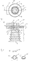
- Fig. 1a illustrates a bottom view of a first embodiment of a handling device 100 comprising a suction cup 10 and a docking piece 30. Details of the suction cup 10 and the docking piece 30 will become further apparent from the following figures and description.
- FIG. 1a The illustration of the handling device 100 of Fig. 1a illustrates an inside of the suction cup 10 from below, i.e. its open end which is configured for contacting the foodstuff to be handled.
- the suction cup 10 comprises an outlet nozzle 16 which is located on an opposite side of the docking piece 30 being attached to the suction cup 10 in an upper region of the suction cup 10.
- a non-return valve 28 can be seen in Fig. 1a which is located at the top of the actual cup and will be further described in connection with Figs. 1b and 2 below.
- the embodiment according to Fig. 1a comprises two openings 18, 20 which will also be described in further detail below and are, in this embodiment, located on opposing sides of the non-return valve 28 in a radial direction with respect to the substantially circularly shaped bottom of the suction cup 10.
- Fig. 1b illustrates a sectional side view of the embodiment of Fig. 1a , taken along the plane indicated as line A-A in Fig. 1a .
- Fig. 1b illustrates the outlet nozzle 16 in sectional view.
- a drive opening 14 Aligned with the outlet nozzle 16 is a drive opening 14 which is configured for receiving a drive nozzle 32, the drive nozzle 32 being part of the docking piece 30.
- the suction cup 10 comprises an intake portion 26, a space surrounding the drive nozzle 32 and the entry of the outlet nozzle 16.
- the outlet nozzle 16 illustrated in Fig. 1b comprises a constriction by which the fluid entering the outlet nozzle is accelerated.
- This constriction is preferably present in the outlet nozzle 16 but is not essential for the present invention.
- the presence of a constriction is not related or linked to any other feature of the outlet nozzle 16, the drive nozzle 32 or any other member of the mechanism illustrated in Fig. 1a and 1b .
- the outlet nozzle 16 comprises more than one constriction, for example as a stepped cross section.
- the embodiment of Fig. 1 comprises the non-return valve 28 mentioned above with regard to Fig. 1a .
- the non-return valve 28 allows fluid to flow upwards towards the intake portion 26 driven by the negative pressure or vacuum created in the intake portion 26.
- the elements of the suction cup 10 above the non-return valve 28, i. e in particular the drive opening 14, the outlet nozzle 16 and the intake portion 26, form an ejector portion 13 of the suction cup 10. If combined with the drive nozzle 32 of the docking piece 30, the ejector portion 13 provides an ejector so that a vacuum can be generated.
- the non-return valve 28 allows for preventing fluid from flowing from the intake portion 26, the outlet nozzle 16, the inlet opening 14 or drive nozzle 32 towards the suction opening 12. In this way, the vacuum and, therefore, the suction force within the bellows portion 11 acting on the surface of the foodstuff contacting the suction opening 12, can be maintained even when the pressurized fluid is no longer applied to the drive nozzle.
- the suction cup 10 comprises a bellows portion 11 which is substantially formed by a bellows-shaped, generally tapered surrounding wall extending from near the position of the non-return valve 28 to a suction opening 12 at the bottom part of the suction cup 10.
- the suction opening 12 is configured for contacting foodstuff to be handled by the handling device 100. If the surface of foodstuff to be handled by the handling device 100 is properly contacted by the suction opening 12, the vacuum generated in the intake portion 26 will result in the generation of a vacuum of similar strength within the bellows portion 11, thereby generating a suction force which acts on the foodstuff the surface of which being contacted by the suction opening 12.
- the high-pressure fluid which is provided to the drive nozzle 32 of the docking piece 30 is led to the drive nozzle 32 via a pressure line, bore, hole, in the connecting piece 30 ending in a terminal 44 for attaching a pressure source, such as a pump or a pressurized fluid source, or a pressure line connecting the terminal 44 to a pressure source.
- a pressure source such as a pump or a pressurized fluid source
- a hole 31 is provided which corresponds to a supporting structure for the docking piece 30 in this example. Via this supporting structure, the docking piece 30 can be attached to a supporting structure such as a robot arm or a traverse. Of course, it is possible that the docking piece 30 has different means for it to be coupled or connected to a supporting device.
- Fig. 2a illustrates a top view of an example of a non-return valve 28 used in the embodiment of Fig. 1 above.
- the non-return valve 28 comprises a flap which can be bent in one direction but cannot be bent into the opposite direction.
- Fig. 2b illustrates a sectional view of the non-return valve 28 taken along the plane illustrated as line C-C in Fig. 2a .
- Fig. 2c illustrates a perspective view of the non-return valve 28.
- Fig. 3 shows a further embodiment of a handling device 100.
- the embodiment of Fig. 3 is similar to the embodiment of Fig. 1 .
- the embodiment of Fig. 3 differs from the embodiment of Fig. 1 in that it does not comprise the non-return valve 28 illustrated in Figs. 1 and 2 .
- any negative pressure within the bellows portion 11 will be equalized as soon as the high-pressure fluid flow through the drive nozzle 32 and the outlet nozzle 16 is stopped, unless additional valves are provided at applicable positions along the stream of fluid.
- the non-return valve 28 of the embodiment illustrated in Fig. 1 slightly reduces the negative pressure in the bellows portion and, further, is an additional part which results in additional cost of the suction cup 10. If compared to the embodiment according to Fig. 1 , the embodiment according to Fig. 3 maximizes the suction force at the suction opening 12 and reduces the cost for the suction cup 10 at the expense of losing the ability to maintain the vacuum inside of the bellows portion 11, in the absence of any additional means, if the ejector is not operated.
- Fig. 4 illustrates a perspective view of a handling device 100 comprising the suction cup 10 and the docking piece 30 described above.
- Fig. 4 illustrates that the docking piece 30 is locked to the suction cup 10 by means of two posts 34.1, 34.2 which will be described in more detail further below.
- Fig. 4 illustrates a further terminal 40 which is in fluid communication with the opening 18 illustrated in Figs. 1 and 3 and which will also be further described below in more detail.
- the docking piece 30 illustrated in Fig. 4 comprises, in addition to the hole 31, four further holes 33 which are located in a square configuration around the hole 31.
- the five holes 31, 33 provide for attaching the docking piece 30 to a support member, e. g. of a robot or traverse, for holding the handling device 100.
- a support member e. g. of a robot or traverse
- the means for supporting the docking piece 30 are not related to the handling device 100 or any part thereof.
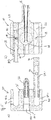
- Fig. 5 illustrates a sectional top view of a suction cup 10 and a docking piece 30, respectively.
- the docking piece 30 is illustrated to comprise the drive nozzle 32 as a separate piece which is attached to a body 35 of the docking piece 30.
- the body 35 is preferably made of stainless steel, whereas the drive nozzle 32 is preferably made of plastic.
- the body 35 and the drive nozzle 32 being "made of" a certain material means that these elements are predominantly made of the respective material. This also covers that relatively small parts or separate elements such as an o-ring or seal, an inlay or coating can be formed of a different material such as a different metal, plastic or rubber.
- the drive nozzle 32 is in fluid communication with the terminal 44 to which a high-pressure fluid source can be connected, for example via a pressure line or similar means.
- the terminal 44 comprises a threading 50.3.
- a hose cartridge connector can be used for the terminal 44.
- a similar or same threading as the threading 50.3 is provided at the further terminal 40 as threading 50.1 and a further terminal 42 as further threading 50.2.
- a hose cartridge connector can be used as an alternative to the threading 50.1, 50.2.
- the further terminals 40, 42 in the body 35 of the docking piece 30 provide for a fluid communication to an inside of posts 34.1, 34.2 which posts respectively comprise an opening 46, 48.
- the openings 46, 48 are located and dimensioned such that they can cooperate with a respective opening 18, 20 in the suction cup 10, as will be described in more detail further below.
- the terminals 40, 42 are in fluid communication with the suction cup 10, in particular an inside of the bellows portion 11 of the suction cup 10.
- the posts 34.1, 34.2 of the docking piece 30 can be made of stainless steel as the body 35 of the docking piece 30, or of a different material such as molded plastic.
- the posts 34.1, 34.2 are preferably provided with a locking element 36, 38 which locking element is configured to engage with a portion of the suction cup 10 in order to removably lock the suction cup 10 to the docking piece 30.
- the left hand part of Fig. 5, Fig. 5a illustrates a first possible realization of the post 34.1 and locking element 36, wherein the locking element 36 is realized by a circumferential projection at the end of the post 34.1.
- the locking element 36 is located and sized to engage with a corresponding recess in the suction cup 10.
- the locking element 36 provides for an increased resistance avoiding that the suction cup 10 can accidentally be removed from the docking piece 30. Purposely removing the suction cup 10 from the docking piece 30 is, however, possible, preferably even manually and without using complex tools.
- An alternative post 34.2 illustrated on the right hand side of Fig. 5, Fig. 5b uses a different realization of a locking element 38.
- the locking element 38 on the post 34.2 comprises a recess which is configured and sized to engage with a respective projection of the suction cup 10.
- the illustrations of the posts 34.1, 34.2 and the respective locking elements 36, 38 are meant as an exemplary illustration of possible ways to securely attach the suction cup 10 to the docking piece 30.
- the suction cup 10 comprises two bores 22, 24 which are dimensioned and configured to receive at least partially the posts 34.1, 34.2, respectively.
- the bores 22, 24 extend parallel to each other and to the drive opening 14 and the outlet nozzle 16 of the suction cup 10.
- the bores 22, 24 are located on two opposing sides with regard to the drive nozzle 32, drive opening 14 and outlet nozzle 16.
- This configuration provides for a particularly tight and secure connection between the docking piece 30 and the suction cup 10.
- the drive nozzle 32 and the drive opening 14, respectively can provide for a locking element in addition to its function of generating the negative pressure within the intake portion 26 and, thereby, generating the suction force at the suction opening 12.
- the openings 18, 20 in the suction cup 10, if substantially aligned with the openings 46, 48 in the posts 34.1, 34.2 provide for a fluid communication between the inside of the suction cup 10 and, via the openings 46, 48 and an inside of the posts 34.1, 34.2, the terminals 40, 42.
- This fluid communication can be used for applying a positive pressure to the inside of the suction cup 10, thereby facilitating and expediting releasing of the foodstuff handled by the handling device 100 from the suction opening 12. Releasing an object that is properly contacted by the suction opening 12 is not always achieved easily, even after stopping the vacuum source, i. e. the operation of the ejector.
- a positive pressure can be applied to the inside of the suction cup 10 overcoming any suction force so that the foodstuff is easily and quickly released from the suction cup 10.
- one or both of the openings 18, 20 can be used for sensing the positive or negative pressure inside of the bellows portion 11 of the suction cup 10.
- the fluid communication between the inside of the suction cup 10 and the terminals 40, 42 allows for attaching a pressure sensor to one of these terminals 40, 42, or a pressure line connected thereto, which facilitates monitoring the operation of the handling device 100.
- it can be monitored whether a negative pressure exists inside of the suction cup 10 which would mean that the suction cup 10 applies a suction force to an object. If the pressure inside of the suction cup 10 is equal to the ambient pressure, the suction cup 10 applies no suction force to any object.
- providing a pressure sensor allows for easily controlling an ejector or other parts of the handling device 100.
- Fig. 6 illustrates a slightly different embodiment of a handling device 100 in a similar illustration as Fig. 5 .
- the terminals 40, 42, 44 of the docking piece 30 of Fig. 6 are provided in a different way.
- post 34.2 is configured in accordance with the configuration of the post 34.1 in Fig. 5 . Accordingly, both posts 34.1, 34.2 comprise a projection on their ends as the locking element 36.
- Fig. 7 illustrates a further embodiment in a similar view as Figs. 5 and 6 .
- the terminals 40, 42, 44 of Fig. 7 are similar to the terminals of Fig. 5 and both posts 34.1, 34.2 are configured in the way as illustrated in Fig. 6 , i. e. with a projection 36 as the locking element for securely attaching the suction cup 10 to the docking piece 30.
- a unitary piece is provided as the suction cup 10 that comprises a conventional suction cup, i.e. the bellows portion 11, and an outlet nozzle 16 of an ejector as well as an intake portion 26. Accordingly, this unitary piece-suction cup 10 can be replaced without the need to replace additional parts of the ejector.
- the suction cup 10 according to the illustrated embodiments comprises not only the bellows portion 11 but also the ejector portion 13 comprising those elements of the ejector which are, with respect to the fluid flow necessary for handling foodstuff, located downstream of the contact area, i. e. the suction opening 12.
- any part of the handling device 100 downstream of any possible contamination resulting from contact with contaminated foodstuff can easily be replaced in regular intervals in order to maintain a hygienic operation of the system.
- the invention avoids cost and time required for replacing other parts of the device such as the drive nozzle 32 or further upstream elements of the ejector or its periphery.
- the drive nozzle 32 is integrally formed with the suction cup 10.
- Such a configuration can be achieved as a unitary piece or as a combination of the drive nozzle 32, on the one hand, and the unitary piece of suction cup 10 comprising the outlet nozzle 16, on the other hand.
- the drive nozzle 32 may be securely attached to the suction cup 10.
- the docking piece 30 provides for a terminal or interface for tightly and mechanically securely connecting the docking piece 30 and the suction cup 10.
- the above illustrated embodiments disclose the suction cup 10 to have three bores, openings or holes, of substantially cylindrical shape.
- One of the bores is used as the drive opening 14, whereas two further bores 22, 24 are used for receiving respective posts 34.1, 34.2 of the docking piece 30.
- two further bores 22, 24 are used for receiving respective posts 34.1, 34.2 of the docking piece 30.
- a different geometric configuration is chosen for fluid-tight connection between the docking piece 30 comprising the drive nozzle 32 and possibly posts 34.1, 34.2 and the suction cup 10.
- one of the openings 18, 20 of the suction cup 10, when cooperating with the openings 46, 48 and terminals 40, 42 of the docking piece 30, can be used to provide a blow-off function for facilitating a release operation of foodstuff carried by the suction cup 10, or for a pressure sensor for monitoring the pressure inside of the suction cup 10, in particular the bellows portion 11.
- a pressure sensor for monitoring the pressure inside of the suction cup 10, in particular the bellows portion 11.
- these optional features are omitted.
- monitoring the suction force applied by the suction opening 12 it is possible to use a camera, optical sensor or other means instead of a pressure sensor.
- a single opening 18, 20 may be in fluid communication with a T-section, where the fluid line branches into two fluid lines, one for a pressure sensor and the other one for a fluid pressure source used for the blow-off function.
- connections of the terminals 40, 42, 44 are provided with a threading.
- a hose cartridge connector or similar means are used for both providing a mechanical connection between the docking piece 30 and the suction cup 10 and for providing a fluid line between the openings 18, 20 and the terminals 40, 42.
- these posts exclusively serve as mechanical connections.
Description
- The present invention relates to a suction cup for handling foodstuff, a docking piece configured for supporting a suction cup and a handling device configured for being attached to a handling apparatus for handling foodstuff,
- Vacuum pumps are known which use a source of compressed air or other high-pressure fluid in order to generate a negative pressure or vacuum in a surrounding space, which can be provided as an intake portion of the pump communicating with other parts of the pump or an interface, such as a suction cup, to an object to which the vacuum is to be applied. Compressed air-driven ejectors operate by accelerating the high-pressure air through a drive nozzle and ejecting it as an air jet at high speed across a gap between the drive nozzle and an outlet flow passage or nozzle. A fluid medium in the surrounding space between the drive nozzle and outlet nozzle, e. g. the intake portion, is entrained into the high-speed flow of compressed air, and the jet flow of entrained medium and air originating from the compressed air source is ejected through the outlet nozzle. As the fluid in the space between the drive and outlet nozzles is ejected in this way, a negative pressure or vacuum is created in the volume surrounding the air jet, e.g. in the intake portion, which this fluid or medium previously occupied.
- Such vacuum pumps can be provided with a suction cup or a similar device so that the negative pressure or vacuum created by the vacuum pump in the intake portion acts on the inside of the walls of the suction cup, thereby providing for a suction force which can be applied to a surface of an object which thus can be handled. Such a mechanism is generally known to be used for handling small to medium-sized articles, in particular foodstuff such as peppers, tomatoes, sausages, meat in the form of non-processed meat or in the form of hamburger patties, chocolate confectionary, chocolate bars, bread etc. If the foodstuff articles are contacted by the suction cup of a respective handling device, the suction cup is at risk of being contaminated by bacterial growth which not only applies to the contacting area itself, but also for any element downstream of the suction cup, i. e. in particular any outlet nozzle of the vacuum pump. If bacterial growth reaches the contacting area, foodstuff handled by the suction cup may be contaminated.
- In order to avoid a health risk due to a possible contamination of parts of the handling device, the suction cup and any downstream element ought to be regularly replaced. This maintenance procedure is both time-consuming and expensive, depending on the number and complexity of the parts to be replaced.
-
GB 1 230 070 GB 1 230 070 -
GB 1 036 586 -
US 2006/0284357 A1 illustrates a workpiece holding system, wherein pressurized air is circulated through a nozzle of an ejector unit of a chuck at all times to make the inside of a suction chamber a negative pressure before chucking a workpiece. - In view of the above-outlined problems of the prior art, it is an object of the present invention to provide a handling device which allows for maintaining a hygienic operation of a handling device using an ejector and a suction cup for handling foodstuff at a reduced maintenance effort. Accordingly, an object of the invention is providing a handling device using an ejector and a suction cup for handling foodstuff which allows for efficient, in particular quick and cost-efficient, maintenance.
- This problem is solved by the suction cup according to claim 1, the docking piece according to claim 5 and the handling device according to
claim 10. Preferred further developments and features of the present invention are subject to the dependent claims and the following detailed description of the invention. - A suction cup for handling foodstuff according to the present invention comprises a suction opening for applying a suction force to a surface of the foodstuff to be handled, a drive opening for receiving a separate drive nozzle, and an outlet nozzle having at least one constriction which outlet nozzle is aligned with the drive opening, wherein the suction cup is configured for being removably attached to a docking piece for supporting the suction cup.
- The suction force applied via the suction opening to the surface of the foodstuff generally results from a negative pressure or vacuum inside of the suction cup. This mechanism as the basis for handling devices using suction cups is generally known in the art, in particular for handling small and medium-sized articles.
- The drive opening of the suction cup according to the present invention is a hole, for example a bore, which is sized and shaped for receiving a drive nozzle which drive nozzle is not part of the suction cup, but can separately be inserted into the drive opening and be removed therefrom. The drive opening may comprise means for providing a fluid-tight, in particular an air-tight connection between the periphery of the drive opening and the separate drive nozzle. Alternatively or additionally, the drive nozzle may comprise such means. Means for providing a fluid-tight connection are generally known from the prior art and could be formed by a separate seal, e. g. an o-ring, or by a corresponding shape and appropriate material properties, in particular elasticity, of a contacting surface of the drive nozzle and/or the drive opening.
- According to the invention, the outlet nozzle comprises at least one constriction for accelerating the fluid to be led through it. It is possible that the outlet nozzle comprises a single constriction or more than one constriction. Also, it is possible that the outlet nozzle has a stepped cross section with a specific series of relative constrictions along the flow of fluid through the outlet nozzle. In the context of the present invention, a constriction means a portion of a fluid channel relatively having a relatively narrow cross section with regard to adjacent portions of the fluid channel on an upstream and a downstream side of the constriction.
- That the suction cup according to the present invention is configured for being removably attached to a docking piece means that it can be attached to the docking piece and removed from it without destroying or damaging it. Preferably, removing the suction cup from the docking piece allows readily replacing the suction cup by a new suction cup to be attached to the docking piece.
- The suction cup as described herein forms a possibly contaminated part of a handling device comprising the suction cup and a docking piece. In other words, the suction cup comprises those elements of the handling device which are located downstream of the source for possible contamination, the surface of the handled foodstuff.
- The outlet nozzle is integrally formed with the suction cup as a unitary piece.
- This reduces manufacturing cost of the suction cup. For example, the suction cup can be formed as one piece by injection molding or similar methods generally known in the art. The outlet nozzle preferably is made of the same material as the remaining portion of the suction cup.
- AS an alternative, the suction cup comprising the outlet nozzle can be manufactured using two-component injection molding and can, therefore, be composed of two different materials. Alternatively, it is possible that the outlet nozzle is formed separately and combined with the remaining portion to form the suction cup according to the present invention.
- The suction cup according to the invention is configured such that the drive nozzle, when received in the drive opening, and the outlet nozzle cooperate to form an ejector for providing a suction force to the suction opening. According to this preferred feature, the drive nozzle and the outlet nozzle directly define a gap between each other across which the fluid, e. g. high-pressure air, entrains fluid, e. g. air, occupying the gap so that a flow of fluid from the gap out of the outlet nozzle is generated which results in a negative pressure in the space surrounding the gap and previously occupied by the fluid. As an alternative, it is possible that the drive nozzle received in the drive opening is configured to guide the high pressure fluid towards a further nozzle which ejects the high pressure fluid across the gap and into the output nozzle. In this exemplary configuration, the drive nozzle and the outlet nozzle would indirectly define the gap required for the function of the ejector.
- In a preferred embodiment, the suction cup further comprises a blow-off opening for applying positive pressure to the inside of the suction cup. The blow-off opening is in communication with the suction opening and preferably communicates with a first hole for connecting a pressure source to the blow-off opening.
- The provision of a blow-off opening allows for facilitating a releasing operation in which the foodstuff object carried by the suction cup is released from the suction cup. By applying the positive pressure through the blow-off opening, any remaining suction force is overturned so that the foodstuff object is immediately released. Alternatively, it is possible that no such blow-off opening is provided. In this case, stopping operation of the ejector results in the negative pressure to more slowly equalize so that it may take longer to release the foodstuff object from the suction cup, if compared to applying a positive pressure through a blow-off opening or similar means.
- The first hole, with which the blow-off opening preferably communicates, is part of the suction cup and can be configured to receive a post or similar part of a docking piece carrying also the drive nozzle received in the drive opening. In this way, it is easily possible to provide the positive pressure to the blow-off opening without much additional effort, in particular via the docking piece. Further preferably, the suction cup comprising a vacuum sensor opening, for sensing a pressure level inside of the suction cup, wherein the vacuum sensor opening preferably communicates with a second hole for connecting a vacuum sensor to the vacuum sensor opening.
- Providing a vacuum sensor is helpful for several applications generally being known from the prior art. In particular, it is possible to use the vacuum sensor for monitoring a vacuum, and thus a configuration in which a foodstuff object is contacted and being held by the suction opening in order to confirm that proper operation of the suction cup is maintained. Further, a vacuum sensor can be used for controlling a pump or other pressure source for providing high pressure fluid to the drive nozzle in order to operate the ejector. Also the second hole, with which the vacuum sensor opening preferably communicates, is part of the suction cup and can be configured to receive a post or similar part of a docking piece carrying also the drive nozzle received in the drive opening. In this way, it is easily possible to provide the pressure from inside of the suction cup to a vacuum sensor without much additional effort, in particular via the docking piece.
- In a preferred embodiment, the suction cup further comprises a non-return valve placed between the outlet nozzle and the suction opening. The non-return valve is capable of blocking a fluid flow towards the suction opening and allows a fluid flow from the suction opening towards the outlet nozzle.
- The non-return valve, therefore, increases safety of the handling operation because, for example, even when the pressure source is switched off or disconnected from the drive nozzle so that negative pressure is no longer generated, the negative pressure on the suction opening side of the non-return valve can be maintained as a fluid flow towards the suction opening is blocked by the non-return valve. However, as an alternative, it is possible that no non-return valve is provided which reduces the cost of the suction cup and may slightly increase the suction force which can be applied via the suction opening as the non-return valve between the outlet nozzle and the suction opening consumes some of the suction force for being opened.
- According to a further aspect, the present invention lies in a docking piece configured for, on the one hand, supporting a suction cup as described above being removably attached to it and, on the other hand, configured for being attached to a handling apparatus for handling foodstuff. The docking piece comprises a drive nozzle which is configured for being inserted into the suction cup attached to the docking piece for ejecting a fluid from the drive nozzle inside of the suction cup, and an interface for functionally connecting the docking piece to the handling apparatus.
- The docking piece and the suction cup described before are interrelated products. The docking piece is sized and shaped such that the suction cup can readily be attached to the docking piece and removed therefrom, in particular in order to replace the suction cup by a new suction cup. The ability to exchange only the suction cup without a need to also replace the docking piece comprising the drive nozzle and possibly terminals and peripheral devices allows for reduction of parts as well as a reduction of costs for the parts to be exchanged in order to maintain a hygienic handling of foodstuff using a suction cup. Therefore, the docking piece, as well as the suction cup, allow for efficient, in particular quick and cost-efficient, maintenance of a handling device for handling foodstuff using suction force.
- The docking piece configured for being attached to the handling apparatus forms an interface between the handling apparatus and the possibly contaminated part of the handling system. The docking piece is part of the handling device which is not possibly contaminated as its elements are located upstream of the possible source of contamination, the surface of the foodstuff handled by the device. In this function, the docking piece may, for being connected to the handling apparatus, have a common "footprint" for establishing a connection to the robot, traverse or other means supporting and moving the handling apparatus including the docking piece.
- Preferably, the docking piece further comprises at least one locking element for providing a mechanically locked connection between the docking piece and the suction cup. Further preferably, the locking element comprises a snap fit element, in particular a projection or a recess, for cooperating with the suction cup, preferably wherein the locking element is provided on a post of the docking piece for engaging a hole in the suction cup.
- The preferred locking element ensures a secure mechanical connection between the docking piece and the suction cup. On the other hand, the locking element may facilitate attaching the suction cup to the docking piece as it is, in a preferred embodiment, configured such that it provides a positive feedback to the user as soon as the suction cup is correctly attached to the docking piece. An example for such a locking element is a snap fit element which is configured to snap in when the suction cup is correctly positioned on the docking piece. If the docking piece comprises a post which is configured for engaging a corresponding hole or bore in the suction cup, the locking element can preferably be provided on the post thereby further improving the connection between the suction cup and the docking piece.
- In a preferred embodiment, the docking piece further comprises at least one terminal in fluid communication with at least one opening so that, when the suction cup is attached to the docking piece, a fluid communication between the suction cup and the at least one terminal can be established. Further preferably, the at least one terminal is provided with a threading or hose cartridge connector.
- The terminal or terminals provided in this preferred embodiment facilitate attaching a vacuum sensor, a pressure source for a blow-off operation or a pressure source for providing the high-pressure fluid to the drive nozzle. In order that a fluid communication is established between the respective terminal and the suction cup, an opening of the docking piece is dimensioned, located and configured to cooperate with a corresponding opening in the suction cup, for example the blow-off opening and the vacuum sensor opening. Alternatively, it is possible that the docking piece is connected to a high-pressure fluid source, a pressure source, a vacuum sensor or any other means using other connection means generally known from the art. Preferably, the docking piece is predominantly made of stainless steel and, further preferably, the drive nozzle is predominantly made of molded plastic. Stainless steel is preferred because this material is particularly hygienic. Forming the drive nozzle from plastic is preferred over forming it also from stainless steel as precision machining of stainless steel is much more difficult than machining plastic at the same level of precision. For example, the drive nozzle may have an aperture at its tip of a radius of 0.003 mm which is difficult to achieve in stainless steel. It is generally preferred, if the drive nozzle and the docking piece are not integrally formed as a unitary piece, that the drive nozzle is threaded into the docking piece and thus connected to it.
- In a preferred embodiment, the docking piece comprises a first post configured for engaging a first hole of the suction cup and a second post configured for engaging a second hole of the suction cup, wherein the first post and the second post comprise an opening in fluid communication with a first terminal and a second terminal, wherein the openings preferably are located at a circumferential position of the first and second post, wherein the first terminal and the second terminal preferably are provided with a threading or hose cartridge connector.
- The first and second holes of the suction cup are described further above also in connection with the preferred provision of posts to cooperate with these holes. It is possible that openings such as the blow-off opening or the vacuum sensor opening are provided in the walls of the holes and are sized, located and configured such that one of the openings of the suction cup and a respective one of the openings of the docking piece are in fluid communication. This means that they may overlap or otherwise allow a fluid flow from the one opening to the other opening for example through a channel formed by a groove on the circumference of the respective post and the inner surface of the respective hole. The openings of the posts are in fluid communication with the respective terminals preferably via an internal fluid line inside of and along the extension of the respective post. In this way, mechanical and functional aspects of a connection between the docking piece and the suction cup are advantageously combined. As an alternative for mainly mechanical connection but also with the option of providing a further function, the posts can be configured as substantially circularly cylindrical rods, but also as dovetail connectors, T-slots or rods of different basic shape such as oval or having the shape of a square, rectangle, triangle or other polygonal form.
- A handling device according to the present invention is configured for being attached to a handling apparatus for handling foodstuff. A handling apparatus for handling foodstuff can e. g. be a robot or a traverse and conveying system to which the handling device comprising the above described suction cup and the above described docking piece is applied as some sort of interface between the handling apparatus and the foodstuff to be handled. The docking piece supports the suction cup, whilst the suction cup is removably attached to the docking piece. The docking piece comprises a drive nozzle inserted into the suction cup, which suction cup is attached to the docking piece, so that a fluid ejected from the drive nozzle passes into the suction cup, and an interface for functionally connecting the docking piece to the handling apparatus. On the other hand, the suction cup comprises a drive opening receiving the drive nozzle of the docking piece, an outlet nozzle having at least one constriction, which outlet nozzle is aligned with the drive nozzle, so that the drive nozzle and the outlet nozzle cooperate to form an ejector, and a suction opening for applying a suction force provided by the ejector to a surface of the foodstuff to be handled.
- The handling device comprises both a possibly contaminated portion and a not possibly contaminated portion of the handling system. According to the configuration of the handling device comprising a suction cup and a docking piece, the handling device can easily be disassembled by removing and replacing the suction cup so that it is very easy and does not require much effort to carry out all necessary maintenance for maintaining a hygienic condition of the handling device and, thus, the complete handling apparatus over an extended period of time. In other words, it is particularly easy to replace any possibly contaminated parts of the system with new parts without the need to replace also parts of the handling device which are not possibly contaminated from contacting contaminated foodstuff.
- Using at least one of a handling device as described above, a suction cup as described above, and a docking piece as described above for handling foodstuff solves the object of the present invention. In particular, it is possible to very efficiently maintain a hygienic condition of the handling apparatus, the handling device and the docking piece by simply replacing the suction cup in regular intervals.
- As a conclusion, the inventors found that it is possible to identify possibly contaminated parts of a handling system and to decouple them from other parts thereof. Thus, the possibly contaminated parts can be integrated into a structure which can be readily replaced, preferably as a one-piece structure, and recycled. This way, it is possible to, firstly, carry out maintenance procedures quickly and, secondly, avoid unnecessary costs and waste if compared to an exchange of the whole ejector-suction cup system. Contrary to prior designs with, for instance, a screw-on suction cup, where the designs entailed screwing the suction cup onto something which was a complete pump, i.e. included the drive nozzle and the outlet nozzle, the invention has split the drive nozzle off the remainder of the pump so that the remainder of the pump can selectively, easily and quickly be replaced. Further features and advantages of the present invention become apparent from the following description of the drawings and preferred embodiments and the claims attached.
-
-
Fig. 1 illustrates a first embodiment of a handling device for handling foodstuff.Fig. 1a is a bottom view,Fig. 1b is a sectional side view taken along line A-A ofFig. 1a . -
Fig. 2 illustrates an embodiment of a non-return valve used in the embodiment according toFig. 1. Fig. 2a is a top view,Fig. 2b is a sectional side view taken along line C-C ofFig. 2a, Fig. 2c is a perspective view. -
Fig. 3 illustrates a further embodiment of a handling device for handling foodstuff.Fig. 3a is a bottom view andFig. 3b is a sectional side view taken along line A-A ofFig. 3a . -
Fig. 4 illustrates a perspective view of an embodiment of a handling device. -
Fig. 5 illustrates a sectional view of an embodiment of elements of a handling device. -
Fig. 6 illustrates a sectional view of a further embodiment of elements of a handling device. -
Fig. 7 illustrates in a sectional view a further embodiment of elements of a handling device. - In the following description, like elements are assigned to like numerals and reference signs and a repetitive description of elements being illustrated in more than one figure is partly omitted.
-
Fig. 1a illustrates a bottom view of a first embodiment of ahandling device 100 comprising asuction cup 10 and adocking piece 30. Details of thesuction cup 10 and thedocking piece 30 will become further apparent from the following figures and description. - The illustration of the
handling device 100 ofFig. 1a illustrates an inside of thesuction cup 10 from below, i.e. its open end which is configured for contacting the foodstuff to be handled. Apart from the walls that make up the actual cup, thesuction cup 10 comprises anoutlet nozzle 16 which is located on an opposite side of thedocking piece 30 being attached to thesuction cup 10 in an upper region of thesuction cup 10. Anon-return valve 28 can be seen inFig. 1a which is located at the top of the actual cup and will be further described in connection withFigs. 1b and 2 below. In the vicinity of thenon-return valve 28, the embodiment according toFig. 1a comprises twoopenings non-return valve 28 in a radial direction with respect to the substantially circularly shaped bottom of thesuction cup 10. -
Fig. 1b illustrates a sectional side view of the embodiment ofFig. 1a , taken along the plane indicated as line A-A inFig. 1a . As to thesuction cup 10,Fig. 1b illustrates theoutlet nozzle 16 in sectional view. Aligned with theoutlet nozzle 16 is adrive opening 14 which is configured for receiving adrive nozzle 32, thedrive nozzle 32 being part of thedocking piece 30. Between thedrive nozzle 32 and an entry of theoutlet nozzle 16, thesuction cup 10 comprises anintake portion 26, a space surrounding thedrive nozzle 32 and the entry of theoutlet nozzle 16. Compressed fluid such as air being accelerated and ejected by thedrive nozzle 32 and flowing into theoutlet nozzle 16 entrains the surrounding fluid in theintake portion 26, thereby generating a negative pressure or vacuum in theintake portion 26. Theoutlet nozzle 16 illustrated inFig. 1b comprises a constriction by which the fluid entering the outlet nozzle is accelerated. This constriction is preferably present in theoutlet nozzle 16 but is not essential for the present invention. Further, the presence of a constriction is not related or linked to any other feature of theoutlet nozzle 16, thedrive nozzle 32 or any other member of the mechanism illustrated inFig. 1a and 1b . Further, it is possible that theoutlet nozzle 16 comprises more than one constriction, for example as a stepped cross section. - Beneath the
intake portion 26, the embodiment ofFig. 1 comprises thenon-return valve 28 mentioned above with regard toFig. 1a . On the one hand, thenon-return valve 28 allows fluid to flow upwards towards theintake portion 26 driven by the negative pressure or vacuum created in theintake portion 26. The elements of thesuction cup 10 above thenon-return valve 28, i. e in particular thedrive opening 14, theoutlet nozzle 16 and theintake portion 26, form anejector portion 13 of thesuction cup 10. If combined with thedrive nozzle 32 of thedocking piece 30, theejector portion 13 provides an ejector so that a vacuum can be generated. On the other hand, thenon-return valve 28 allows for preventing fluid from flowing from theintake portion 26, theoutlet nozzle 16, the inlet opening 14 or drivenozzle 32 towards thesuction opening 12. In this way, the vacuum and, therefore, the suction force within the bellows portion 11 acting on the surface of the foodstuff contacting thesuction opening 12, can be maintained even when the pressurized fluid is no longer applied to the drive nozzle. - Beneath the
non-return valve 28, thesuction cup 10 comprises a bellows portion 11 which is substantially formed by a bellows-shaped, generally tapered surrounding wall extending from near the position of thenon-return valve 28 to asuction opening 12 at the bottom part of thesuction cup 10. Thesuction opening 12 is configured for contacting foodstuff to be handled by thehandling device 100. If the surface of foodstuff to be handled by thehandling device 100 is properly contacted by thesuction opening 12, the vacuum generated in theintake portion 26 will result in the generation of a vacuum of similar strength within the bellows portion 11, thereby generating a suction force which acts on the foodstuff the surface of which being contacted by thesuction opening 12. - The high-pressure fluid which is provided to the
drive nozzle 32 of thedocking piece 30 is led to thedrive nozzle 32 via a pressure line, bore, hole, in the connectingpiece 30 ending in a terminal 44 for attaching a pressure source, such as a pump or a pressurized fluid source, or a pressure line connecting the terminal 44 to a pressure source. - In the upper part of the
docking piece 30, ahole 31 is provided which corresponds to a supporting structure for thedocking piece 30 in this example. Via this supporting structure, thedocking piece 30 can be attached to a supporting structure such as a robot arm or a traverse. Of course, it is possible that thedocking piece 30 has different means for it to be coupled or connected to a supporting device. -
Fig. 2a illustrates a top view of an example of anon-return valve 28 used in the embodiment ofFig. 1 above. Thenon-return valve 28 comprises a flap which can be bent in one direction but cannot be bent into the opposite direction.Fig. 2b illustrates a sectional view of thenon-return valve 28 taken along the plane illustrated as line C-C inFig. 2a . Further,Fig. 2c illustrates a perspective view of thenon-return valve 28. -
Fig. 3 shows a further embodiment of ahandling device 100. The embodiment ofFig. 3 is similar to the embodiment ofFig. 1 . The embodiment ofFig. 3 differs from the embodiment ofFig. 1 in that it does not comprise thenon-return valve 28 illustrated inFigs. 1 and 2 . - In the embodiment of
Fig. 3 , without thenon-return valve 28 ofFigs. 1 and 2 , any negative pressure within the bellows portion 11 will be equalized as soon as the high-pressure fluid flow through thedrive nozzle 32 and theoutlet nozzle 16 is stopped, unless additional valves are provided at applicable positions along the stream of fluid. On the other hand, thenon-return valve 28 of the embodiment illustrated inFig. 1 slightly reduces the negative pressure in the bellows portion and, further, is an additional part which results in additional cost of thesuction cup 10. If compared to the embodiment according toFig. 1 , the embodiment according toFig. 3 maximizes the suction force at thesuction opening 12 and reduces the cost for thesuction cup 10 at the expense of losing the ability to maintain the vacuum inside of the bellows portion 11, in the absence of any additional means, if the ejector is not operated. -
Fig. 4 illustrates a perspective view of ahandling device 100 comprising thesuction cup 10 and thedocking piece 30 described above. In addition to the illustrations ofFigs. 1 and3 ,Fig. 4 illustrates that thedocking piece 30 is locked to thesuction cup 10 by means of two posts 34.1, 34.2 which will be described in more detail further below. Also,Fig. 4 illustrates afurther terminal 40 which is in fluid communication with theopening 18 illustrated inFigs. 1 and3 and which will also be further described below in more detail. - The
docking piece 30 illustrated inFig. 4 comprises, in addition to thehole 31, fourfurther holes 33 which are located in a square configuration around thehole 31. The fiveholes docking piece 30 to a support member, e. g. of a robot or traverse, for holding thehandling device 100. Of course, different means for supporting thedocking piece 30 will be apparent to the skilled person. The means for supporting thedocking piece 30 are not related to thehandling device 100 or any part thereof. -
Fig. 5 illustrates a sectional top view of asuction cup 10 and adocking piece 30, respectively. - In the left hand part of
Fig. 5 , thedocking piece 30 is illustrated to comprise thedrive nozzle 32 as a separate piece which is attached to abody 35 of thedocking piece 30. Thebody 35 is preferably made of stainless steel, whereas thedrive nozzle 32 is preferably made of plastic. Thebody 35 and thedrive nozzle 32 being "made of" a certain material means that these elements are predominantly made of the respective material. This also covers that relatively small parts or separate elements such as an o-ring or seal, an inlay or coating can be formed of a different material such as a different metal, plastic or rubber. - The
drive nozzle 32 is in fluid communication with the terminal 44 to which a high-pressure fluid source can be connected, for example via a pressure line or similar means. In order to securely attach the high-pressure fluid source to thedocking piece 30, the terminal 44 comprises a threading 50.3. Alternatively, a hose cartridge connector can be used for the terminal 44. - A similar or same threading as the threading 50.3 is provided at the
further terminal 40 as threading 50.1 and afurther terminal 42 as further threading 50.2. Also for theseterminals further terminals body 35 of thedocking piece 30 provide for a fluid communication to an inside of posts 34.1, 34.2 which posts respectively comprise anopening openings respective opening suction cup 10, as will be described in more detail further below. In this way, theterminals suction cup 10, in particular an inside of the bellows portion 11 of thesuction cup 10. - The posts 34.1, 34.2 of the
docking piece 30 can be made of stainless steel as thebody 35 of thedocking piece 30, or of a different material such as molded plastic. The posts 34.1, 34.2 are preferably provided with a lockingelement suction cup 10 in order to removably lock thesuction cup 10 to thedocking piece 30. The left hand part ofFig. 5, Fig. 5a , illustrates a first possible realization of the post 34.1 and lockingelement 36, wherein the lockingelement 36 is realized by a circumferential projection at the end of the post 34.1. The lockingelement 36 is located and sized to engage with a corresponding recess in thesuction cup 10. Accordingly, when thesuction cup 10 is attached to thedocking piece 30, the lockingelement 36 provides for an increased resistance avoiding that thesuction cup 10 can accidentally be removed from thedocking piece 30. Purposely removing thesuction cup 10 from thedocking piece 30 is, however, possible, preferably even manually and without using complex tools. - An alternative post 34.2 illustrated on the right hand side of
Fig. 5, Fig. 5b , uses a different realization of a lockingelement 38. The lockingelement 38 on the post 34.2 comprises a recess which is configured and sized to engage with a respective projection of thesuction cup 10. The illustrations of the posts 34.1, 34.2 and therespective locking elements suction cup 10 to thedocking piece 30. - Of course, the skilled person will readily appreciate further possible realizations of a reliable attachment of the
suction cup 10 to thedocking piece 30 including a mechanism for locking or latching thesuction cup 10 to thedocking piece 30. - As is illustrated in
Fig. 5b , thesuction cup 10 comprises twobores bores drive opening 14 and theoutlet nozzle 16 of thesuction cup 10. Preferably, thebores drive nozzle 32, drive opening 14 andoutlet nozzle 16. This configuration provides for a particularly tight and secure connection between thedocking piece 30 and thesuction cup 10. However, it is of course possible to use different means for securely attaching thesuction cup 10 to thedocking piece 30 so that thesuction cup 10 can be supported by thedocking piece 30. For example, it is possible to modify thedrive nozzle 32 and thedrive opening 14, respectively, so that thedrive nozzle 32 can provide for a locking element in addition to its function of generating the negative pressure within theintake portion 26 and, thereby, generating the suction force at thesuction opening 12. - The
openings suction cup 10, if substantially aligned with theopenings suction cup 10 and, via theopenings terminals - This fluid communication can be used for applying a positive pressure to the inside of the
suction cup 10, thereby facilitating and expediting releasing of the foodstuff handled by thehandling device 100 from thesuction opening 12. Releasing an object that is properly contacted by thesuction opening 12 is not always achieved easily, even after stopping the vacuum source, i. e. the operation of the ejector. In order to facilitate the separation and, therefore, in order to increase the possible handling speed, a positive pressure can be applied to the inside of thesuction cup 10 overcoming any suction force so that the foodstuff is easily and quickly released from thesuction cup 10. - Alternatively or additionally, one or both of the
openings suction cup 10. The fluid communication between the inside of thesuction cup 10 and theterminals terminals handling device 100. In particular, it can be monitored whether a negative pressure exists inside of thesuction cup 10 which would mean that thesuction cup 10 applies a suction force to an object. If the pressure inside of thesuction cup 10 is equal to the ambient pressure, thesuction cup 10 applies no suction force to any object. Further, providing a pressure sensor allows for easily controlling an ejector or other parts of thehandling device 100. -
Fig. 6 illustrates a slightly different embodiment of ahandling device 100 in a similar illustration asFig. 5 . In contrast to the embodiment ofFig. 5 , theterminals docking piece 30 ofFig. 6 are provided in a different way. Further, also post 34.2 is configured in accordance with the configuration of the post 34.1 inFig. 5 . Accordingly, both posts 34.1, 34.2 comprise a projection on their ends as the lockingelement 36. -
Fig. 7 illustrates a further embodiment in a similar view asFigs. 5 and6 . In contrast to the embodiment ofFig. 6 , theterminals Fig. 7 are similar to the terminals ofFig. 5 and both posts 34.1, 34.2 are configured in the way as illustrated inFig. 6 , i. e. with aprojection 36 as the locking element for securely attaching thesuction cup 10 to thedocking piece 30. - In the illustrated embodiments, a unitary piece is provided as the
suction cup 10 that comprises a conventional suction cup, i.e. the bellows portion 11, and anoutlet nozzle 16 of an ejector as well as anintake portion 26. Accordingly, this unitary piece-suction cup 10 can be replaced without the need to replace additional parts of the ejector. Thesuction cup 10 according to the illustrated embodiments comprises not only the bellows portion 11 but also theejector portion 13 comprising those elements of the ejector which are, with respect to the fluid flow necessary for handling foodstuff, located downstream of the contact area, i. e. thesuction opening 12. This means that any part of thehandling device 100 downstream of any possible contamination resulting from contact with contaminated foodstuff can easily be replaced in regular intervals in order to maintain a hygienic operation of the system. At the same time, the invention avoids cost and time required for replacing other parts of the device such as thedrive nozzle 32 or further upstream elements of the ejector or its periphery. - In an alternative embodiment, it is possible that also the
drive nozzle 32 is integrally formed with thesuction cup 10. Such a configuration can be achieved as a unitary piece or as a combination of thedrive nozzle 32, on the one hand, and the unitary piece ofsuction cup 10 comprising theoutlet nozzle 16, on the other hand. In the latter case, thedrive nozzle 32 may be securely attached to thesuction cup 10. In this case, it is preferable that thedocking piece 30 provides for a terminal or interface for tightly and mechanically securely connecting thedocking piece 30 and thesuction cup 10. Further, the above illustrated embodiments disclose thesuction cup 10 to have three bores, openings or holes, of substantially cylindrical shape. One of the bores is used as thedrive opening 14, whereas twofurther bores docking piece 30. However, it is of course possible that a different geometric configuration is chosen for fluid-tight connection between thedocking piece 30 comprising thedrive nozzle 32 and possibly posts 34.1, 34.2 and thesuction cup 10. - As described above, one of the
openings suction cup 10, when cooperating with theopenings terminals docking piece 30, can be used to provide a blow-off function for facilitating a release operation of foodstuff carried by thesuction cup 10, or for a pressure sensor for monitoring the pressure inside of thesuction cup 10, in particular the bellows portion 11. However, it is of course possible that these optional features are omitted. With particular regard to monitoring the suction force applied by thesuction opening 12, it is possible to use a camera, optical sensor or other means instead of a pressure sensor. Also, it is possible to use only asingle opening single opening - As mentioned before, it is preferred that the connections of the
terminals docking piece 30 and thesuction cup 10 and for providing a fluid line between theopenings terminals optional openings suction cup 10 without removing thedocking piece 30 is possible. - By using the present invention, it is possible to quickly replace only those parts of a vacuum handling device which are possibly contaminated after having contacted foodstuff. Parts of the ejector and handling device which are upstream or isolated with regard to the foodstuff and any possible bacterial or other contamination are not required to be replaced at the same interval so that the present invention allows for significantly increasing the efficiency of the complete handling device.
Claims (12)
- Suction cup (10) for handling foodstuff, wherein the suction cup (10) comprises
a suction opening (12) for applying a suction force to a surface of the foodstuff to be handled,
a drive opening (14) for receiving a separate drive nozzle (32),
characterized by
an outlet nozzle (16) integrally formed with the suction cup (10) as a unitary piece and having at least one constriction for accelerating a fluid to be led through it which outlet nozzle (16) is aligned with the drive opening (14), wherein the drive nozzle (32), when received in the drive opening (14), and the outlet nozzle (16) cooperate to form an ejector for providing a suction force to the suction opening (12),
wherein the suction cup (10) is configured for being removably attached to a docking piece (30) for supporting the suction cup (10). - Suction cup (10) according to claim 1, further comprising a blow-off opening (18), for applying positive pressure to the inside of the suction cup (10), which blow-off opening (18) is in communication with the suction opening (12),
wherein the blow-off opening (18) preferably communicates with a first hole (22) for connecting a pressure source to the blow-off opening (18). - Suction cup (10) according to any of the preceding claims, further comprising a vacuum sensor opening (20), for sensing a pressure level inside of the suction cup (10),
wherein the vacuum sensor opening (20) preferably communicates with a second hole (24) for connecting a vacuum sensor to the vacuum sensor opening (20). - Suction cup (10) according to any of the preceding claims, further comprising a non-return valve (28) placed between the outlet nozzle (16) and the suction opening (12), the non-return valve (28) being capable of blocking a fluid flow towards the suction opening (12) and allowing a fluid flow from the suction opening (12) towards the outlet nozzle (16).
- Docking piece (30), the docking piece (30) being configured for supporting the suction cup (10) according to any of claims 1 to 4 removably attached to it and the docking piece (30) being configured for being attached to a handling apparatus for handling foodstuff, the docking piece (30) comprising
a drive nozzle (32) which is configured for being inserted into the suction cup (10) attached to the docking piece (30) for ejecting a fluid from the drive nozzle (32) inside of the suction cup (10), and
an interface for functionally connecting the docking piece (30) to the handling apparatus,
further comprising at least one locking element (36, 38) for providing a mechanically locked connection between the docking piece (30) and the suction cup (10),
wherein the locking element comprises a snap fit element (36, 38) for cooperating with the suction cup (10) and
wherein the locking element (36, 38) is provided on a post (34.1, 34.2) of the docking piece (30) for engaging a hole (22, 24) in the suction cup (10). - Docking piece (30) of claim 5, wherein the snap fit element (36, 38) is a projection (36) or a recess (38).
- Docking piece (30) of claim 5 or 6, further comprising at least one terminal (40, 42) in fluid communication with at least one opening (46, 48) so that, when the suction cup (10) is attached to the docking piece (30), a fluid communication between the suction cup (10) and the at least one terminal (40, 42) can be established,
preferably wherein the at least one terminal (40, 42) is provided with a threading (50.1, 50.2) or hose cartridge connector. - Docking piece (30) of any of claims 5 to 7, wherein the docking piece (30) is predominantly made of stainless steel,
wherein preferably the drive nozzle (32) is predominantly made of molded plastic. - Docking piece (30) of any of claims 5 to 8, comprising a first post (34.1) configured for engaging a first hole (22) of the suction cup (10) and a second post (34.2) configured for engaging a second hole (24) of the suction cup (10),
wherein the first post (34.1) and the second post (34.2) comprise an opening (46, 48) in fluid communication with a first terminal (40) and a second terminal (42),
wherein the openings (46, 48) preferably are located at a circumferential position of the first and second post (34.1, 34.2),
wherein the first terminal (40) and the second terminal (42) preferably are provided with a threading (50.1, 50.2) or hose cartridge connector. - Handling device (100) configured for being attached to a handling apparatus for handling foodstuff, comprising the suction cup (10) according to any of claims 1 to 4 and the docking piece (30) according to any of claims 5 to 9 supporting the suction cup (10), wherein the suction cup (10) is removably attached to the docking piece (30),
whereinthe drive nozzle (32) is inserted into the suction cup (10), the suction cup being attached to the docking piece (30) so that fluid ejected from the drive nozzle (32) passes into the suction cup (10), and
whereinthe drive opening (14) receives the drive nozzle (32) of the docking piece (30), andthe outlet nozzle (16) is aligned with the drive nozzle (32), so that the drive nozzle (32) and the outlet nozzle (16) cooperate to form an ejector. - Handling device (100) according to claim 10, wherein the docking piece (30) comprises at least one terminal (40, 42) in fluid communication with an inside of the suction cup (10).
- Use of at least one of a handling device (100) according to claim 10 or 11, a suction cup (10) according to any of claims 1 to 4, and a docking piece (30) according to any of claims 5 to 9 for handling foodstuff.
Priority Applications (1)
| Application Number | Priority Date | Filing Date | Title |
|---|---|---|---|
| DE15760399.4T DE15760399T1 (en) | 2014-10-13 | 2015-08-21 | HANDLING DEVICE WITH SUCTION CUP FOR FOOD |
Applications Claiming Priority (2)
| Application Number | Priority Date | Filing Date | Title |
|---|---|---|---|
| GBGB1418117.6A GB201418117D0 (en) | 2014-10-13 | 2014-10-13 | Handling device for foodstuff |
| PCT/EP2015/069242 WO2016058737A1 (en) | 2014-10-13 | 2015-08-21 | Handling device with suction cup for foodstuff |
Publications (2)
| Publication Number | Publication Date |
|---|---|
| EP3206974A1 EP3206974A1 (en) | 2017-08-23 |
| EP3206974B1 true EP3206974B1 (en) | 2020-07-08 |
Family
ID=52001351
Family Applications (1)
| Application Number | Title | Priority Date | Filing Date |
|---|---|---|---|
| EP15760399.4A Active EP3206974B1 (en) | 2014-10-13 | 2015-08-21 | Handling device with suction cup for foodstuff |
Country Status (7)
| Country | Link |
|---|---|
| US (1) | US10457499B2 (en) |
| EP (1) | EP3206974B1 (en) |
| JP (1) | JP6575018B2 (en) |
| CN (1) | CN107074460B (en) |
| DE (1) | DE15760399T1 (en) |
| GB (1) | GB201418117D0 (en) |
| WO (1) | WO2016058737A1 (en) |
Families Citing this family (10)
| Publication number | Priority date | Publication date | Assignee | Title |
|---|---|---|---|---|
| GB2509184A (en) | 2012-12-21 | 2014-06-25 | Xerex Ab | Multi-stage vacuum ejector with moulded nozzle having integral valve elements |
| GB2509182A (en) | 2012-12-21 | 2014-06-25 | Xerex Ab | Vacuum ejector with multi-nozzle drive stage and booster |
| CN105026772B (en) | 2012-12-21 | 2018-03-30 | 谢雷克斯公司 | Vacuum ejector ozzle with oval divergent portion |
| GB2509183A (en) | 2012-12-21 | 2014-06-25 | Xerex Ab | Vacuum ejector with tripped diverging exit flow nozzle |
| CN107972059A (en) * | 2017-12-22 | 2018-05-01 | 微可为(厦门)真空科技有限公司 | A kind of detachable suction lip and automation suction device |
| US10520009B2 (en) | 2018-02-13 | 2019-12-31 | NFR Investments Pty. Ltd. | Consumer product suction cup ensemble |
| DE102018111487B4 (en) * | 2018-05-14 | 2021-12-30 | J. Schmalz Gmbh | Holding device for a suction gripper in a vacuum handling device |
| EP3879139B1 (en) | 2020-03-12 | 2022-06-08 | Piab Aktiebolag | Compressible suction cup having additional vacuum compartment, as well as lip, and bellows therefor |
| IL273316B (en) * | 2020-03-15 | 2021-02-28 | Tevel Aerobotics Tech Ltd | Device and method for fruit harvesting |
| CN112497250B (en) * | 2020-12-08 | 2022-08-16 | 苏州富强科技有限公司 | Sucker assembly capable of positioning and stirring |
Family Cites Families (122)
| Publication number | Priority date | Publication date | Assignee | Title |
|---|---|---|---|---|
| BE486879A (en) | ||||
| US1137767A (en) | 1906-07-26 | 1915-05-04 | Expl Des Procedes Westinghouse Leblanc Sa | Ejector. |
| US1415406A (en) | 1917-06-01 | 1922-05-09 | British Westinghouse Electric | Elastic-fluid-operated ejector |
| US1406145A (en) | 1920-12-23 | 1922-02-07 | Firm Of Alex Friedmann | Injector |
| US1536180A (en) | 1922-12-27 | 1925-05-05 | Electric Water Sterilizer & Oz | Eductor |
| US1491057A (en) | 1923-04-30 | 1924-04-22 | Benjamin F Myers | Pump |
| US1902729A (en) | 1931-08-15 | 1933-03-21 | Schmidt Paul | Multistage liquid driven ejector for delivering liquids |
| US2011224A (en) | 1933-01-20 | 1935-08-13 | Kobiolke Adolf Gustav | Apparatus for producing vacuum |
| US2074480A (en) | 1936-03-18 | 1937-03-23 | Ingersoll Rand Co | Thermocompressor |
| US2200800A (en) * | 1939-09-28 | 1940-05-14 | F J Littel Machine Co | Plate lifter |
| US2375180A (en) | 1943-11-08 | 1945-05-01 | Vigo George | Apparatus for jet propulsive and other purposes |
| GB790459A (en) | 1955-07-25 | 1958-02-12 | Schiff And Stern Ges M B H | Improvements in or relating to injector devices |
| US3143401A (en) | 1961-08-17 | 1964-08-04 | Gen Electric | Supersonic fuel injector |
| FR82913E (en) * | 1962-11-05 | 1964-05-08 | Bertin & Cie | Improvements to vacuum support devices |
| US3292378A (en) | 1964-04-10 | 1966-12-20 | Moisture Miser Systems Pomona | Subsurface irrigation conduit |
| US3371618A (en) | 1966-02-18 | 1968-03-05 | Chambers John | Pump |
| US3474953A (en) | 1969-03-05 | 1969-10-28 | Air Vac Eng Co Inc | Vacuum creating device |
| US3568959A (en) * | 1969-04-09 | 1971-03-09 | Leland F Blaff | Vacuum cup type work gripping means |
| JPS4722393Y1 (en) | 1969-04-15 | 1972-07-21 | ||
| US3694107A (en) | 1970-11-19 | 1972-09-26 | Nash Engineering Co | Ejector apparatus and method of utilizing same |
| FR2174782B1 (en) | 1972-03-10 | 1975-03-21 | Lafourcade Jean Michel | |
| JPS48102496A (en) | 1972-03-10 | 1973-12-22 | ||
| US3838002A (en) | 1972-07-21 | 1974-09-24 | Gen Electric | Jet pump for nuclear reactor |
| US3967849A (en) | 1973-06-14 | 1976-07-06 | Sahlin International, Inc. | Vacuum control system |
| US4037991A (en) | 1973-07-26 | 1977-07-26 | The Plessey Company Limited | Fluid-flow assisting devices |
| US4158528A (en) | 1973-09-12 | 1979-06-19 | Air-Vac Engineering Co., Inc. | Gas-operated vacuum transducer |
| SE370765B (en) | 1973-12-05 | 1974-10-28 | Piab Ab | |
| JPS5142101A (en) | 1974-10-07 | 1976-04-09 | Mitsubishi Heavy Ind Ltd | DEIFUYUUZAA |
| JPS56109989A (en) | 1980-01-30 | 1981-08-31 | Toshiba Corp | Lubricating oil apparatus |
| SE427955B (en) | 1980-05-21 | 1983-05-24 | Piab Ab | MULTIEJEKTOR |
| DE3025525A1 (en) | 1980-07-05 | 1982-01-28 | Jürgen 4477 Welver Volkmann | EJECTOR DEVICE |
| US4358249A (en) | 1980-10-14 | 1982-11-09 | The United States Of America As Represented By The United States Department Of Energy | Vacuum chamber with a supersonic flow aerodynamic window |
| US4519423A (en) | 1983-07-08 | 1985-05-28 | University Of Southern California | Mixing apparatus using a noncircular jet of small aspect ratio |
| US4634560A (en) | 1984-02-29 | 1987-01-06 | Aluminum Company Of America | Aspirator pump and metering device |
| FR2575678B1 (en) | 1985-01-04 | 1988-06-03 | Saint Gobain Vitrage | PNEUMATIC POWDER EJECTOR |
| FR2580191B1 (en) | 1985-04-11 | 1989-10-06 | Bayen Jean | REDUCED PRESSURE DRYING PROCESS OF A GAS-FILLED WET ENCLOSURE |
| US4790054A (en) | 1985-07-12 | 1988-12-13 | Nichols William O | Multi-stage venturi ejector and method of manufacture thereof |
| JPH0426229Y2 (en) | 1986-10-30 | 1992-06-24 | ||
| US4759691A (en) | 1987-03-19 | 1988-07-26 | Kroupa Larry G | Compressed air driven vacuum pump assembly |
| US4880358A (en) | 1988-06-20 | 1989-11-14 | Air-Vac Engineering Company, Inc. | Ultra-high vacuum force, low air consumption pumps |
| GB2242504B (en) | 1990-03-27 | 1994-04-06 | Hartley Simon Ltd | A flap valve |
| AU630797B2 (en) | 1990-04-05 | 1992-11-05 | Spraying Systems Co. | Quick disconnect nozzle assembly |
| JP2713814B2 (en) | 1990-11-15 | 1998-02-16 | 三井造船株式会社 | Ejector for compressible fluid |
| DE4037935A1 (en) | 1990-11-23 | 1992-05-27 | Mannesmann Ag | BEAM COMPRESSOR FOR GAS-MEDIA |
| US5201560A (en) | 1991-01-24 | 1993-04-13 | John A. Blatt | Vacuum cup control apparatus |
| US5277468A (en) | 1991-01-30 | 1994-01-11 | John A. Blatt | Vacuum control apparatus |
| JP2989030B2 (en) | 1991-04-06 | 1999-12-13 | 光洋精工株式会社 | Fluid pressure pulsation reduction device |
| US5228839A (en) | 1991-05-24 | 1993-07-20 | Gast Manufacturing Corporation | Multistage ejector pump |
| US5320497A (en) | 1991-06-26 | 1994-06-14 | Smc Kabushiki Kaisha | Vacuum feeding apparatus |
| SE469291B (en) | 1991-10-31 | 1993-06-14 | Piab Ab | EJECTOR ARRANGEMENTS INCLUDING AT LEAST TWO PRESSURIZED EJECTORS AND PROCEDURAL PROVIDES THAT WITH A MINIMUM TWO PRESSURE AIRED EJECTORS ACHIEVES A DIFFERENT PREVENTION OF A MINIMUM DIFFICULTY OF A MINIMUM DIFFICULTY OF A MINIMUM DIFFICULTY OF A MINIMUM DIFFICULTY OF A MINIMUM DIFFICULTY OF A MINIMUM DIFFICULTY OF A MINIMUM DIFFICULTY OF A MINIMUM DIFFICULTY OF A MINIMUM DIFFICULTY OF A MINIMUM DIFFICULTY. |
| IL100168A0 (en) | 1991-11-27 | 1992-08-18 | Dan Greenberg | High vacuum pump |
| DE9210497U1 (en) | 1992-08-06 | 1993-12-09 | Volkmann Thilo | Ejector |
| US6017195A (en) | 1993-02-12 | 2000-01-25 | Skaggs; Bill D. | Fluid jet ejector and ejection method |
| US5683227A (en) | 1993-03-31 | 1997-11-04 | Smc Corporation | Multistage ejector assembly |
| JP3678760B2 (en) | 1993-08-09 | 2005-08-03 | Smc株式会社 | Multistage ejector device |
| JPH07299787A (en) | 1994-05-07 | 1995-11-14 | Shibuya Kogyo Co Ltd | Suction device with washing mechanism |
| DE4425601A1 (en) | 1994-07-06 | 1996-01-18 | Mannesmann Ag | Process for operating a jet pump and a jet pump itself |
| FR2727608B1 (en) | 1994-12-06 | 1997-01-10 | Oreal | DISPENSER FOR A LIQUID CONSISTENCY PRODUCT WITH PASTE |
| JPH08232900A (en) | 1995-02-28 | 1996-09-10 | Toshiba Corp | Jet pump |
| DE19512700A1 (en) | 1995-04-07 | 1996-10-10 | Teves Gmbh Alfred | Jet pump |
| AUPN347395A0 (en) | 1995-06-09 | 1995-07-06 | Casey, Alan Patrick | Nozzle for delivering a liquid/gas mixture |
| DE19606020B4 (en) | 1996-02-19 | 2008-04-17 | Siemens Ag | Intended for use in a fuel tank of a motor vehicle suction jet pump |
| US5979889A (en) | 1997-04-15 | 1999-11-09 | Heidelberger, Druckmaschinen Ag | Apparatus for generating a vacuum |
| SE511716E5 (en) | 1998-03-20 | 2009-01-28 | Piab Ab | ejector |
| JP3938394B2 (en) | 1998-10-01 | 2007-06-27 | シーケーディ株式会社 | Ejector |
| US20010035222A1 (en) | 1999-04-28 | 2001-11-01 | Anges Cour | Assembly of extruded or moulded parts |
| KR100433282B1 (en) | 1999-07-09 | 2004-05-27 | 한국뉴매틱(주) | Ejector array and its arrangement method |
| DE29916531U1 (en) | 1999-09-20 | 2001-02-08 | Volkmann Thilo | Ejector |
| US6209563B1 (en) | 2000-01-07 | 2001-04-03 | Saturn Electronics & Engineering, Inc. | Solenoid control valve |
| US7547674B2 (en) | 2001-06-06 | 2009-06-16 | New York Medical College | Methods and compositions for the repair and/or regeneration of damaged myocardium |
| FR2816027B1 (en) | 2000-10-27 | 2003-07-04 | Nicoll Raccords Plastiques | FLEXIBLE HYDRAULIC CONNECTION |
| DE10061384B4 (en) | 2000-12-09 | 2007-01-18 | Festo Ag & Co. | Jet pump arrangement for generating vacuum and method for operating such a jet pump arrangement |
| DE50112524D1 (en) | 2001-08-30 | 2007-07-05 | Festo Ag & Co | Vacuum generator device |
| JP4132897B2 (en) | 2002-03-19 | 2008-08-13 | 株式会社日本ピスコ | Vacuum generator |
| SE0201335L (en) | 2002-05-03 | 2003-03-25 | Piab Ab | Vacuum pump and ways to provide vacuum |
| US6877960B1 (en) | 2002-06-05 | 2005-04-12 | Flodesign, Inc. | Lobed convergent/divergent supersonic nozzle ejector system |
| DE10250532B3 (en) | 2002-10-29 | 2004-07-01 | J. Schmalz Gmbh | Propellant powered ejector assembly |
| US6976645B2 (en) | 2003-07-30 | 2005-12-20 | Kabushiki Kaisha Hitachi Seisakusho | Ejector for use with pneumatic booster |
| US20050061378A1 (en) | 2003-08-01 | 2005-03-24 | Foret Todd L. | Multi-stage eductor apparatus |
| ES2336579T3 (en) | 2004-02-26 | 2010-04-14 | Pursuit Dynamics Plc. | IMPROVEMENTS RELATED TO A DEVICE FOR GENERATING A FOG. |
| JP4134931B2 (en) | 2004-03-30 | 2008-08-20 | 株式会社デンソー | Ejector |
| DE102004034670B3 (en) | 2004-07-17 | 2005-10-27 | Festo Ag & Co. | Vacuum nozzle has a compressed air channel which terminates in Venturi-type nozzle connected to gripper nozzle via suction zone connected to suction channel, Venturi nozzle being made from elastomer |
| US7497666B2 (en) | 2004-09-21 | 2009-03-03 | George Washington University | Pressure exchange ejector |
| GB0502495D0 (en) | 2005-02-07 | 2005-03-16 | Boc Group Plc | Ejector pump |
| US8100866B2 (en) | 2005-03-24 | 2012-01-24 | B. Braun Medical Inc. | Needleless access port valves |
| JP4635717B2 (en) | 2005-05-24 | 2011-02-23 | 株式会社デンソー | Work holding method and holding device |
| US20070003001A1 (en) | 2005-06-30 | 2007-01-04 | General Electric Company | Method for mitigation oxide fouling in structural components in light water reactors |
| US7581374B1 (en) | 2005-09-26 | 2009-09-01 | The Toro Company | Grass cutting unit having compression molded UHMW plastic roller |
| SE0502371L (en) | 2005-10-27 | 2006-09-19 | Xerex Ab | Ejector with mounting sleeve, as well as mounting procedure |
| US20070132149A1 (en) | 2005-11-29 | 2007-06-14 | Hildebrand George R | Methods of making foam nozzles for trigger dispensers |
| KR100629994B1 (en) | 2005-12-30 | 2006-10-02 | 한국뉴매틱(주) | Vacuum ejector pumps |
| DE102006062692B4 (en) * | 2006-02-06 | 2008-08-21 | J. Schmalz Gmbh | Suction pads |
| US7727137B2 (en) | 2006-10-13 | 2010-06-01 | Xoft, Inc. | Balloon brachytherapy applicator and method |
| KR100993678B1 (en) | 2007-12-13 | 2010-11-10 | 현대자동차주식회사 | Multi stage in-line cartridge ejector for fuel cell system |
| SE0702827L (en) | 2007-12-19 | 2008-10-14 | Autolabel Ab | Device for tools and method for making them |
| US20090259316A1 (en) | 2008-04-15 | 2009-10-15 | Ginn Richard S | Spacer Devices and Systems for the Treatment of Spinal Stenosis and Methods for Using the Same |
| DE202008010424U1 (en) | 2008-07-30 | 2009-12-24 | J. Schmalz Gmbh | Air-operated surface suction gripper |
| US20100150743A1 (en) * | 2008-12-12 | 2010-06-17 | Norgren Automotive, Inc. | Single Line Venturi Apparatus |
| JP4961439B2 (en) | 2009-01-22 | 2012-06-27 | 日立Geニュークリア・エナジー株式会社 | Jet pump and reactor |
| JP5338481B2 (en) | 2009-05-26 | 2013-11-13 | 株式会社デンソー | Ejector |
| KR20110019518A (en) * | 2009-08-20 | 2011-02-28 | 삼성전자주식회사 | Nozzle for holding a substrate and apparatus for transferring a substrate including the same |
| JP5370028B2 (en) | 2009-09-10 | 2013-12-18 | 株式会社デンソー | Ejector |
| US8382174B2 (en) * | 2009-10-08 | 2013-02-26 | University Of Maryland | System, method, and apparatus for suction gripping |
| DE102009047085A1 (en) | 2009-11-24 | 2011-06-01 | J. Schmalz Gmbh | Compressed air operated vacuum generator |
| DE102009047083C5 (en) | 2009-11-24 | 2013-09-12 | J. Schmalz Gmbh | Compressed air operated vacuum generator or vacuum gripper |
| TWI391307B (en) * | 2010-01-15 | 2013-04-01 | Advanced Semiconductor Eng | Suction head and transporting machine applying the same |
| US8684434B2 (en) * | 2011-11-02 | 2014-04-01 | AMF automation Technologies, LLC | End effector with internal valve |
| EP2489601A1 (en) | 2011-02-16 | 2012-08-22 | Albéa Services | Tube head provided with a non-rebreathing valve |
| KR20140020944A (en) | 2011-03-28 | 2014-02-19 | 가부시키가이샤 고가네이 | Ejector |
| CN102654145B (en) | 2011-08-31 | 2014-06-25 | 韩铁夫 | Jet pump |
| IL215426A (en) | 2011-09-27 | 2017-10-31 | Dan Geva | Multi-stage vacuum pump |
| CN102530548B (en) * | 2012-01-31 | 2014-01-01 | 宁波大学 | Compound type pneumatic non-contact gas claw |
| CN103423215B (en) | 2012-05-25 | 2015-09-02 | 韩铁夫 | Multiplex compound ejector |
| JP6028993B2 (en) | 2012-06-04 | 2016-11-24 | ニチモウ株式会社 | Transport device |
| DE102012107050A1 (en) * | 2012-08-01 | 2014-02-06 | C. & E. Fein Gmbh | Suction lifter and sealing flange for a siphon |
| JP6131023B2 (en) * | 2012-10-31 | 2017-05-17 | Juki株式会社 | Nozzle replacement mechanism and electronic component mounting apparatus |
| GB2509184A (en) | 2012-12-21 | 2014-06-25 | Xerex Ab | Multi-stage vacuum ejector with moulded nozzle having integral valve elements |
| GB2509182A (en) | 2012-12-21 | 2014-06-25 | Xerex Ab | Vacuum ejector with multi-nozzle drive stage and booster |
| EP2935900A1 (en) | 2012-12-21 | 2015-10-28 | Xerex AB | Vacuum ejector with multi-nozzle drive stage |
| GB2509183A (en) | 2012-12-21 | 2014-06-25 | Xerex Ab | Vacuum ejector with tripped diverging exit flow nozzle |
| ES1079082Y (en) | 2013-03-04 | 2013-07-25 | Milla Carlos Santaolalla | CONNECTOR FOR CONNECTING A COOLED DRIVING WITH A DRINK DISPENSING BARREL |
| EP3163093B1 (en) | 2015-10-30 | 2020-06-17 | Piab Aktiebolag | High vacuum ejector |
-
2014
- 2014-10-13 GB GBGB1418117.6A patent/GB201418117D0/en not_active Ceased
-
2015
- 2015-08-21 WO PCT/EP2015/069242 patent/WO2016058737A1/en active Application Filing
- 2015-08-21 US US15/514,461 patent/US10457499B2/en active Active
- 2015-08-21 JP JP2017519603A patent/JP6575018B2/en active Active
- 2015-08-21 DE DE15760399.4T patent/DE15760399T1/en active Pending
- 2015-08-21 CN CN201580055308.9A patent/CN107074460B/en active Active
- 2015-08-21 EP EP15760399.4A patent/EP3206974B1/en active Active
Non-Patent Citations (1)
| Title |
|---|
| None * |
Also Published As
| Publication number | Publication date |
|---|---|
| DE15760399T1 (en) | 2018-01-18 |
| JP2018500185A (en) | 2018-01-11 |
| US20170275104A1 (en) | 2017-09-28 |
| US10457499B2 (en) | 2019-10-29 |
| JP6575018B2 (en) | 2019-09-18 |
| CN107074460A (en) | 2017-08-18 |
| WO2016058737A1 (en) | 2016-04-21 |
| CN107074460B (en) | 2019-06-25 |
| GB201418117D0 (en) | 2014-11-26 |
| EP3206974A1 (en) | 2017-08-23 |
Similar Documents
| Publication | Publication Date | Title |
|---|---|---|
| EP3206974B1 (en) | Handling device with suction cup for foodstuff | |
| EP2287095B1 (en) | Non-contact type of vacuum pad | |
| EP2810901B1 (en) | Product suction device | |
| KR20010006643A (en) | Contact lens transfer and material removal system | |
| JP2009519826A (en) | Powder coating apparatus and powder supply apparatus therefor | |
| JP2001522338A (en) | Liquid chemical dispensing system with sensor | |
| WO2015182041A1 (en) | Trigger-type liquid sprayer | |
| KR102006259B1 (en) | Washing device for bottles | |
| JP2011117519A (en) | Valve device | |
| JP6535847B2 (en) | Suction hand | |
| KR20190091270A (en) | Dust Removal Device and Dust Removal System | |
| KR20170102208A (en) | Fluid supply apparatus | |
| JP2005163619A (en) | Vacuum generation unit | |
| EP1707277A1 (en) | Method for cleaning and transporting rubber stoppers and apparatus for cleaning and transporting rubber stoppers | |
| JP3773469B2 (en) | Transfer drive device | |
| EP3517788B1 (en) | Vacuum pump using profile | |
| US7547046B2 (en) | Pneumatic conveying line component | |
| JP2018075695A (en) | Gripper | |
| TW202144259A (en) | Non-contact transport device | |
| US5298159A (en) | Filter-collector apparatus | |
| CN111819083B (en) | Attachment, dummy cartridge, method for inserting dummy cartridge into printer | |
| EP3260400A1 (en) | A vacuum system adapted to be used as a vacuum source for at least one gripper device | |
| EP3765279B1 (en) | Device for holding a product, which can be configured as the product is being processed | |
| CN114401914A (en) | Suction unit and suction device | |
| CN210972962U (en) | Nondestructive flexible grabbing system |
Legal Events
| Date | Code | Title | Description |
|---|---|---|---|
| STAA | Information on the status of an ep patent application or granted ep patent |
Free format text: STATUS: THE INTERNATIONAL PUBLICATION HAS BEEN MADE |
|
| PUAI | Public reference made under article 153(3) epc to a published international application that has entered the european phase |
Free format text: ORIGINAL CODE: 0009012 |
|
| STAA | Information on the status of an ep patent application or granted ep patent |
Free format text: STATUS: REQUEST FOR EXAMINATION WAS MADE |
|
| 17P | Request for examination filed |
Effective date: 20170222 |
|
| AK | Designated contracting states |
Kind code of ref document: A1 Designated state(s): AL AT BE BG CH CY CZ DE DK EE ES FI FR GB GR HR HU IE IS IT LI LT LU LV MC MK MT NL NO PL PT RO RS SE SI SK SM TR |
|
| AX | Request for extension of the european patent |
Extension state: BA ME |
|
| REG | Reference to a national code |
Ref country code: FR Ref legal event code: EL |
|
| DAV | Request for validation of the european patent (deleted) | ||
| DAX | Request for extension of the european patent (deleted) | ||
| REG | Reference to a national code |
Ref country code: DE Ref legal event code: R210 Ref document number: 602015055447 Country of ref document: DE Ref country code: DE Ref legal event code: R210 |
|
| RAP1 | Party data changed (applicant data changed or rights of an application transferred) |
Owner name: PIAB AKTIEBOLAG |
|
| STAA | Information on the status of an ep patent application or granted ep patent |
Free format text: STATUS: EXAMINATION IS IN PROGRESS |
|
| 17Q | First examination report despatched |
Effective date: 20191106 |
|
| GRAP | Despatch of communication of intention to grant a patent |
Free format text: ORIGINAL CODE: EPIDOSNIGR1 |
|
| STAA | Information on the status of an ep patent application or granted ep patent |
Free format text: STATUS: GRANT OF PATENT IS INTENDED |
|
| GRAJ | Information related to disapproval of communication of intention to grant by the applicant or resumption of examination proceedings by the epo deleted |
Free format text: ORIGINAL CODE: EPIDOSDIGR1 |
|
| STAA | Information on the status of an ep patent application or granted ep patent |
Free format text: STATUS: EXAMINATION IS IN PROGRESS |
|
| INTG | Intention to grant announced |
Effective date: 20200114 |
|
| GRAP | Despatch of communication of intention to grant a patent |
Free format text: ORIGINAL CODE: EPIDOSNIGR1 |
|
| STAA | Information on the status of an ep patent application or granted ep patent |
Free format text: STATUS: GRANT OF PATENT IS INTENDED |
|
| INTC | Intention to grant announced (deleted) | ||
| INTG | Intention to grant announced |
Effective date: 20200219 |
|
| GRAS | Grant fee paid |
Free format text: ORIGINAL CODE: EPIDOSNIGR3 |
|
| GRAA | (expected) grant |
Free format text: ORIGINAL CODE: 0009210 |
|
| STAA | Information on the status of an ep patent application or granted ep patent |
Free format text: STATUS: THE PATENT HAS BEEN GRANTED |
|
| REG | Reference to a national code |
Ref country code: DE Ref legal event code: R082 Ref document number: 602015055447 Country of ref document: DE Representative=s name: HOFFMANN - EITLE PATENT- UND RECHTSANWAELTE PA, DE |
|
| AK | Designated contracting states |
Kind code of ref document: B1 Designated state(s): AL AT BE BG CH CY CZ DE DK EE ES FI FR GB GR HR HU IE IS IT LI LT LU LV MC MK MT NL NO PL PT RO RS SE SI SK SM TR |
|
| REG | Reference to a national code |
Ref country code: AT Ref legal event code: REF Ref document number: 1288233 Country of ref document: AT Kind code of ref document: T Effective date: 20200715 Ref country code: CH Ref legal event code: EP |
|
| REG | Reference to a national code |
Ref country code: DE Ref legal event code: R096 Ref document number: 602015055447 Country of ref document: DE |
|
| REG | Reference to a national code |
Ref country code: IE Ref legal event code: FG4D |
|
| REG | Reference to a national code |
Ref country code: LT Ref legal event code: MG4D |
|
| REG | Reference to a national code |
Ref country code: AT Ref legal event code: MK05 Ref document number: 1288233 Country of ref document: AT Kind code of ref document: T Effective date: 20200708 |
|
| REG | Reference to a national code |
Ref country code: NL Ref legal event code: MP Effective date: 20200708 |
|
| PG25 | Lapsed in a contracting state [announced via postgrant information from national office to epo] |
Ref country code: SE Free format text: LAPSE BECAUSE OF FAILURE TO SUBMIT A TRANSLATION OF THE DESCRIPTION OR TO PAY THE FEE WITHIN THE PRESCRIBED TIME-LIMIT Effective date: 20200708 Ref country code: GR Free format text: LAPSE BECAUSE OF FAILURE TO SUBMIT A TRANSLATION OF THE DESCRIPTION OR TO PAY THE FEE WITHIN THE PRESCRIBED TIME-LIMIT Effective date: 20201009 Ref country code: FI Free format text: LAPSE BECAUSE OF FAILURE TO SUBMIT A TRANSLATION OF THE DESCRIPTION OR TO PAY THE FEE WITHIN THE PRESCRIBED TIME-LIMIT Effective date: 20200708 Ref country code: BG Free format text: LAPSE BECAUSE OF FAILURE TO SUBMIT A TRANSLATION OF THE DESCRIPTION OR TO PAY THE FEE WITHIN THE PRESCRIBED TIME-LIMIT Effective date: 20201008 Ref country code: ES Free format text: LAPSE BECAUSE OF FAILURE TO SUBMIT A TRANSLATION OF THE DESCRIPTION OR TO PAY THE FEE WITHIN THE PRESCRIBED TIME-LIMIT Effective date: 20200708 Ref country code: NO Free format text: LAPSE BECAUSE OF FAILURE TO SUBMIT A TRANSLATION OF THE DESCRIPTION OR TO PAY THE FEE WITHIN THE PRESCRIBED TIME-LIMIT Effective date: 20201008 Ref country code: LT Free format text: LAPSE BECAUSE OF FAILURE TO SUBMIT A TRANSLATION OF THE DESCRIPTION OR TO PAY THE FEE WITHIN THE PRESCRIBED TIME-LIMIT Effective date: 20200708 Ref country code: AT Free format text: LAPSE BECAUSE OF FAILURE TO SUBMIT A TRANSLATION OF THE DESCRIPTION OR TO PAY THE FEE WITHIN THE PRESCRIBED TIME-LIMIT Effective date: 20200708 Ref country code: HR Free format text: LAPSE BECAUSE OF FAILURE TO SUBMIT A TRANSLATION OF THE DESCRIPTION OR TO PAY THE FEE WITHIN THE PRESCRIBED TIME-LIMIT Effective date: 20200708 Ref country code: PT Free format text: LAPSE BECAUSE OF FAILURE TO SUBMIT A TRANSLATION OF THE DESCRIPTION OR TO PAY THE FEE WITHIN THE PRESCRIBED TIME-LIMIT Effective date: 20201109 |
|
| PG25 | Lapsed in a contracting state [announced via postgrant information from national office to epo] |
Ref country code: IS Free format text: LAPSE BECAUSE OF FAILURE TO SUBMIT A TRANSLATION OF THE DESCRIPTION OR TO PAY THE FEE WITHIN THE PRESCRIBED TIME-LIMIT Effective date: 20201108 Ref country code: RS Free format text: LAPSE BECAUSE OF FAILURE TO SUBMIT A TRANSLATION OF THE DESCRIPTION OR TO PAY THE FEE WITHIN THE PRESCRIBED TIME-LIMIT Effective date: 20200708 Ref country code: PL Free format text: LAPSE BECAUSE OF FAILURE TO SUBMIT A TRANSLATION OF THE DESCRIPTION OR TO PAY THE FEE WITHIN THE PRESCRIBED TIME-LIMIT Effective date: 20200708 Ref country code: LV Free format text: LAPSE BECAUSE OF FAILURE TO SUBMIT A TRANSLATION OF THE DESCRIPTION OR TO PAY THE FEE WITHIN THE PRESCRIBED TIME-LIMIT Effective date: 20200708 |
|
| PG25 | Lapsed in a contracting state [announced via postgrant information from national office to epo] |
Ref country code: NL Free format text: LAPSE BECAUSE OF FAILURE TO SUBMIT A TRANSLATION OF THE DESCRIPTION OR TO PAY THE FEE WITHIN THE PRESCRIBED TIME-LIMIT Effective date: 20200708 |
|
| REG | Reference to a national code |
Ref country code: CH Ref legal event code: PL |
|
| REG | Reference to a national code |
Ref country code: DE Ref legal event code: R097 Ref document number: 602015055447 Country of ref document: DE |
|
| PG25 | Lapsed in a contracting state [announced via postgrant information from national office to epo] |
Ref country code: RO Free format text: LAPSE BECAUSE OF FAILURE TO SUBMIT A TRANSLATION OF THE DESCRIPTION OR TO PAY THE FEE WITHIN THE PRESCRIBED TIME-LIMIT Effective date: 20200708 Ref country code: SM Free format text: LAPSE BECAUSE OF FAILURE TO SUBMIT A TRANSLATION OF THE DESCRIPTION OR TO PAY THE FEE WITHIN THE PRESCRIBED TIME-LIMIT Effective date: 20200708 Ref country code: EE Free format text: LAPSE BECAUSE OF FAILURE TO SUBMIT A TRANSLATION OF THE DESCRIPTION OR TO PAY THE FEE WITHIN THE PRESCRIBED TIME-LIMIT Effective date: 20200708 Ref country code: LU Free format text: LAPSE BECAUSE OF NON-PAYMENT OF DUE FEES Effective date: 20200821 Ref country code: LI Free format text: LAPSE BECAUSE OF NON-PAYMENT OF DUE FEES Effective date: 20200831 Ref country code: IT Free format text: LAPSE BECAUSE OF FAILURE TO SUBMIT A TRANSLATION OF THE DESCRIPTION OR TO PAY THE FEE WITHIN THE PRESCRIBED TIME-LIMIT Effective date: 20200708 Ref country code: CZ Free format text: LAPSE BECAUSE OF FAILURE TO SUBMIT A TRANSLATION OF THE DESCRIPTION OR TO PAY THE FEE WITHIN THE PRESCRIBED TIME-LIMIT Effective date: 20200708 Ref country code: CH Free format text: LAPSE BECAUSE OF NON-PAYMENT OF DUE FEES Effective date: 20200831 Ref country code: DK Free format text: LAPSE BECAUSE OF FAILURE TO SUBMIT A TRANSLATION OF THE DESCRIPTION OR TO PAY THE FEE WITHIN THE PRESCRIBED TIME-LIMIT Effective date: 20200708 |
|
| PLBE | No opposition filed within time limit |
Free format text: ORIGINAL CODE: 0009261 |
|
| STAA | Information on the status of an ep patent application or granted ep patent |
Free format text: STATUS: NO OPPOSITION FILED WITHIN TIME LIMIT |
|
| REG | Reference to a national code |
Ref country code: BE Ref legal event code: MM Effective date: 20200831 |
|
| PG25 | Lapsed in a contracting state [announced via postgrant information from national office to epo] |
Ref country code: AL Free format text: LAPSE BECAUSE OF FAILURE TO SUBMIT A TRANSLATION OF THE DESCRIPTION OR TO PAY THE FEE WITHIN THE PRESCRIBED TIME-LIMIT Effective date: 20200708 |
|
| 26N | No opposition filed |
Effective date: 20210409 |
|
| GBPC | Gb: european patent ceased through non-payment of renewal fee |
Effective date: 20201008 |
|
| PG25 | Lapsed in a contracting state [announced via postgrant information from national office to epo] |
Ref country code: SK Free format text: LAPSE BECAUSE OF FAILURE TO SUBMIT A TRANSLATION OF THE DESCRIPTION OR TO PAY THE FEE WITHIN THE PRESCRIBED TIME-LIMIT Effective date: 20200708 |
|
| PG25 | Lapsed in a contracting state [announced via postgrant information from national office to epo] |
Ref country code: BE Free format text: LAPSE BECAUSE OF NON-PAYMENT OF DUE FEES Effective date: 20200831 Ref country code: SI Free format text: LAPSE BECAUSE OF FAILURE TO SUBMIT A TRANSLATION OF THE DESCRIPTION OR TO PAY THE FEE WITHIN THE PRESCRIBED TIME-LIMIT Effective date: 20200708 Ref country code: GB Free format text: LAPSE BECAUSE OF NON-PAYMENT OF DUE FEES Effective date: 20201008 Ref country code: IE Free format text: LAPSE BECAUSE OF NON-PAYMENT OF DUE FEES Effective date: 20200821 |
|
| PG25 | Lapsed in a contracting state [announced via postgrant information from national office to epo] |
Ref country code: TR Free format text: LAPSE BECAUSE OF FAILURE TO SUBMIT A TRANSLATION OF THE DESCRIPTION OR TO PAY THE FEE WITHIN THE PRESCRIBED TIME-LIMIT Effective date: 20200708 Ref country code: MT Free format text: LAPSE BECAUSE OF FAILURE TO SUBMIT A TRANSLATION OF THE DESCRIPTION OR TO PAY THE FEE WITHIN THE PRESCRIBED TIME-LIMIT Effective date: 20200708 Ref country code: CY Free format text: LAPSE BECAUSE OF FAILURE TO SUBMIT A TRANSLATION OF THE DESCRIPTION OR TO PAY THE FEE WITHIN THE PRESCRIBED TIME-LIMIT Effective date: 20200708 |
|
| PG25 | Lapsed in a contracting state [announced via postgrant information from national office to epo] |
Ref country code: MK Free format text: LAPSE BECAUSE OF FAILURE TO SUBMIT A TRANSLATION OF THE DESCRIPTION OR TO PAY THE FEE WITHIN THE PRESCRIBED TIME-LIMIT Effective date: 20200708 Ref country code: MC Free format text: LAPSE BECAUSE OF FAILURE TO SUBMIT A TRANSLATION OF THE DESCRIPTION OR TO PAY THE FEE WITHIN THE PRESCRIBED TIME-LIMIT Effective date: 20200708 |
|
| P01 | Opt-out of the competence of the unified patent court (upc) registered |
Effective date: 20230526 |
|
| PGFP | Annual fee paid to national office [announced via postgrant information from national office to epo] |
Ref country code: FR Payment date: 20230816 Year of fee payment: 9 Ref country code: DE Payment date: 20230816 Year of fee payment: 9 |