EP3206811B1 - Verfahren zum herstellen einer profilierten hohlwelle für eine teleskopierbare lenkwelle eines kraftfahrzeugs - Google Patents
Verfahren zum herstellen einer profilierten hohlwelle für eine teleskopierbare lenkwelle eines kraftfahrzeugs Download PDFInfo
- Publication number
- EP3206811B1 EP3206811B1 EP15747433.9A EP15747433A EP3206811B1 EP 3206811 B1 EP3206811 B1 EP 3206811B1 EP 15747433 A EP15747433 A EP 15747433A EP 3206811 B1 EP3206811 B1 EP 3206811B1
- Authority
- EP
- European Patent Office
- Prior art keywords
- hollow shaft
- shaft
- profile
- groove
- roller
- Prior art date
- Legal status (The legal status is an assumption and is not a legal conclusion. Google has not performed a legal analysis and makes no representation as to the accuracy of the status listed.)
- Active
Links
- 238000004519 manufacturing process Methods 0.000 title claims description 19
- 238000000034 method Methods 0.000 claims description 15
- 238000005096 rolling process Methods 0.000 description 18
- 230000002093 peripheral effect Effects 0.000 description 11
- 239000000463 material Substances 0.000 description 8
- 238000003754 machining Methods 0.000 description 5
- 230000005540 biological transmission Effects 0.000 description 4
- 238000011161 development Methods 0.000 description 4
- 230000015572 biosynthetic process Effects 0.000 description 3
- 238000013461 design Methods 0.000 description 3
- 238000006073 displacement reaction Methods 0.000 description 3
- 230000008569 process Effects 0.000 description 3
- 230000009467 reduction Effects 0.000 description 3
- 230000000694 effects Effects 0.000 description 2
- 238000002474 experimental method Methods 0.000 description 2
- 239000000314 lubricant Substances 0.000 description 2
- 229910000838 Al alloy Inorganic materials 0.000 description 1
- 206010010904 Convulsion Diseases 0.000 description 1
- 241000209035 Ilex Species 0.000 description 1
- 229910000831 Steel Inorganic materials 0.000 description 1
- 230000009471 action Effects 0.000 description 1
- 238000005452 bending Methods 0.000 description 1
- 230000008901 benefit Effects 0.000 description 1
- 238000005097 cold rolling Methods 0.000 description 1
- 230000008878 coupling Effects 0.000 description 1
- 238000010168 coupling process Methods 0.000 description 1
- 238000005859 coupling reaction Methods 0.000 description 1
- 230000006378 damage Effects 0.000 description 1
- 230000006735 deficit Effects 0.000 description 1
- 238000009826 distribution Methods 0.000 description 1
- 230000008030 elimination Effects 0.000 description 1
- 238000003379 elimination reaction Methods 0.000 description 1
- 238000011835 investigation Methods 0.000 description 1
- 238000000465 moulding Methods 0.000 description 1
- 230000008092 positive effect Effects 0.000 description 1
- 238000012545 processing Methods 0.000 description 1
- 239000010935 stainless steel Substances 0.000 description 1
- 229910001220 stainless steel Inorganic materials 0.000 description 1
- 239000010959 steel Substances 0.000 description 1
- 230000008093 supporting effect Effects 0.000 description 1
Images

Classifications
-
- B—PERFORMING OPERATIONS; TRANSPORTING
- B62—LAND VEHICLES FOR TRAVELLING OTHERWISE THAN ON RAILS
- B62D—MOTOR VEHICLES; TRAILERS
- B62D1/00—Steering controls, i.e. means for initiating a change of direction of the vehicle
- B62D1/02—Steering controls, i.e. means for initiating a change of direction of the vehicle vehicle-mounted
- B62D1/16—Steering columns
-
- F—MECHANICAL ENGINEERING; LIGHTING; HEATING; WEAPONS; BLASTING
- F16—ENGINEERING ELEMENTS AND UNITS; GENERAL MEASURES FOR PRODUCING AND MAINTAINING EFFECTIVE FUNCTIONING OF MACHINES OR INSTALLATIONS; THERMAL INSULATION IN GENERAL
- F16C—SHAFTS; FLEXIBLE SHAFTS; ELEMENTS OR CRANKSHAFT MECHANISMS; ROTARY BODIES OTHER THAN GEARING ELEMENTS; BEARINGS
- F16C3/00—Shafts; Axles; Cranks; Eccentrics
- F16C3/02—Shafts; Axles
- F16C3/03—Shafts; Axles telescopic
-
- B—PERFORMING OPERATIONS; TRANSPORTING
- B21—MECHANICAL METAL-WORKING WITHOUT ESSENTIALLY REMOVING MATERIAL; PUNCHING METAL
- B21D—WORKING OR PROCESSING OF SHEET METAL OR METAL TUBES, RODS OR PROFILES WITHOUT ESSENTIALLY REMOVING MATERIAL; PUNCHING METAL
- B21D15/00—Corrugating tubes
- B21D15/02—Corrugating tubes longitudinally
-
- B—PERFORMING OPERATIONS; TRANSPORTING
- B21—MECHANICAL METAL-WORKING WITHOUT ESSENTIALLY REMOVING MATERIAL; PUNCHING METAL
- B21D—WORKING OR PROCESSING OF SHEET METAL OR METAL TUBES, RODS OR PROFILES WITHOUT ESSENTIALLY REMOVING MATERIAL; PUNCHING METAL
- B21D17/00—Forming single grooves in sheet metal or tubular or hollow articles
- B21D17/04—Forming single grooves in sheet metal or tubular or hollow articles by rolling
-
- B—PERFORMING OPERATIONS; TRANSPORTING
- B21—MECHANICAL METAL-WORKING WITHOUT ESSENTIALLY REMOVING MATERIAL; PUNCHING METAL
- B21H—MAKING PARTICULAR METAL OBJECTS BY ROLLING, e.g. SCREWS, WHEELS, RINGS, BARRELS, BALLS
- B21H1/00—Making articles shaped as bodies of revolution
- B21H1/18—Making articles shaped as bodies of revolution cylinders, e.g. rolled transversely cross-rolling
- B21H1/20—Making articles shaped as bodies of revolution cylinders, e.g. rolled transversely cross-rolling rolled longitudinally
-
- B—PERFORMING OPERATIONS; TRANSPORTING
- B21—MECHANICAL METAL-WORKING WITHOUT ESSENTIALLY REMOVING MATERIAL; PUNCHING METAL
- B21H—MAKING PARTICULAR METAL OBJECTS BY ROLLING, e.g. SCREWS, WHEELS, RINGS, BARRELS, BALLS
- B21H7/00—Making articles not provided for in the preceding groups, e.g. agricultural tools, dinner forks, knives, spoons
- B21H7/18—Making articles not provided for in the preceding groups, e.g. agricultural tools, dinner forks, knives, spoons grooved pins; Rolling grooves, e.g. oil grooves, in articles
- B21H7/187—Rolling helical or rectilinear grooves
-
- B—PERFORMING OPERATIONS; TRANSPORTING
- B21—MECHANICAL METAL-WORKING WITHOUT ESSENTIALLY REMOVING MATERIAL; PUNCHING METAL
- B21K—MAKING FORGED OR PRESSED METAL PRODUCTS, e.g. HORSE-SHOES, RIVETS, BOLTS OR WHEELS
- B21K1/00—Making machine elements
- B21K1/06—Making machine elements axles or shafts
- B21K1/063—Making machine elements axles or shafts hollow
-
- F—MECHANICAL ENGINEERING; LIGHTING; HEATING; WEAPONS; BLASTING
- F16—ENGINEERING ELEMENTS AND UNITS; GENERAL MEASURES FOR PRODUCING AND MAINTAINING EFFECTIVE FUNCTIONING OF MACHINES OR INSTALLATIONS; THERMAL INSULATION IN GENERAL
- F16D—COUPLINGS FOR TRANSMITTING ROTATION; CLUTCHES; BRAKES
- F16D3/00—Yielding couplings, i.e. with means permitting movement between the connected parts during the drive
- F16D3/02—Yielding couplings, i.e. with means permitting movement between the connected parts during the drive adapted to specific functions
- F16D3/06—Yielding couplings, i.e. with means permitting movement between the connected parts during the drive adapted to specific functions specially adapted to allow axial displacement
-
- F—MECHANICAL ENGINEERING; LIGHTING; HEATING; WEAPONS; BLASTING
- F16—ENGINEERING ELEMENTS AND UNITS; GENERAL MEASURES FOR PRODUCING AND MAINTAINING EFFECTIVE FUNCTIONING OF MACHINES OR INSTALLATIONS; THERMAL INSULATION IN GENERAL
- F16C—SHAFTS; FLEXIBLE SHAFTS; ELEMENTS OR CRANKSHAFT MECHANISMS; ROTARY BODIES OTHER THAN GEARING ELEMENTS; BEARINGS
- F16C2326/00—Articles relating to transporting
- F16C2326/20—Land vehicles
- F16C2326/24—Steering systems, e.g. steering rods or columns
-
- F—MECHANICAL ENGINEERING; LIGHTING; HEATING; WEAPONS; BLASTING
- F16—ENGINEERING ELEMENTS AND UNITS; GENERAL MEASURES FOR PRODUCING AND MAINTAINING EFFECTIVE FUNCTIONING OF MACHINES OR INSTALLATIONS; THERMAL INSULATION IN GENERAL
- F16D—COUPLINGS FOR TRANSMITTING ROTATION; CLUTCHES; BRAKES
- F16D2250/00—Manufacturing; Assembly
-
- F—MECHANICAL ENGINEERING; LIGHTING; HEATING; WEAPONS; BLASTING
- F16—ENGINEERING ELEMENTS AND UNITS; GENERAL MEASURES FOR PRODUCING AND MAINTAINING EFFECTIVE FUNCTIONING OF MACHINES OR INSTALLATIONS; THERMAL INSULATION IN GENERAL
- F16D—COUPLINGS FOR TRANSMITTING ROTATION; CLUTCHES; BRAKES
- F16D3/00—Yielding couplings, i.e. with means permitting movement between the connected parts during the drive
- F16D3/16—Universal joints in which flexibility is produced by means of pivots or sliding or rolling connecting parts
- F16D3/26—Hooke's joints or other joints with an equivalent intermediate member to which each coupling part is pivotally or slidably connected
- F16D3/38—Hooke's joints or other joints with an equivalent intermediate member to which each coupling part is pivotally or slidably connected with a single intermediate member with trunnions or bearings arranged on two axes perpendicular to one another
- F16D3/40—Hooke's joints or other joints with an equivalent intermediate member to which each coupling part is pivotally or slidably connected with a single intermediate member with trunnions or bearings arranged on two axes perpendicular to one another with intermediate member provided with two pairs of outwardly-directed trunnions on intersecting axes
Definitions
- the present invention relates to a method for producing a profiled hollow shaft for a telescopic steering shaft of a motor vehicle, comprising the provision of a hollow shaft to be machined as well as a profile mandrel and a roller head having at least one roller, the profile mandrel for producing a groove in the hollow shaft first in the hollow shaft is introduced and then the hollow shaft is moved relative to the roller head.
- Telescopic steering shafts in motor vehicles on the one hand enable the steering column to be adjusted, and on the other hand they are intended to prevent the steering shaft from moving further into the interior of the passenger compartment in the event of a crash and leading to injuries to the occupants. This is usually achieved by providing two mutually telescopic shafts or hollow shafts, which together form a steering shaft. Furthermore, adjustment of the steering wheel position in the longitudinal direction can be achieved due to the telescopability.
- the hollow shafts are provided with profiles which correspond to one another and which on the one hand enable displacement in the longitudinal direction and on the other hand to transmit a torque.
- the profiles must be easy to move and play against each other, it is particularly important to avoid twisting or kinking.
- hollow shafts with high wall thicknesses are conventionally used.
- step-by-step machining is generally carried out, the hollow shafts first being pushed onto a profile mandrel. Molding tools, such as rollers, then act on the outer peripheral surfaces of hollow shafts.
- the hollow shaft can be adapted to the profile of the profile mandrel, and on the other hand a corresponding profile can be created on the outer peripheral surface. Due to the high material thickness of the hollow shafts and the associated high rolling forces, the profiling of the hollow shafts is generally only gradual, with the material flowing.
- the molds work in the longitudinal and circumferential direction step by step over the hollow shaft and thus create the desired profile.
- the step-by-step generation of the profiling of the hollow shafts leads to high cycle times, which drive up the manufacturing costs of the profiled hollow shafts.
- the CH 579427 A5 shows for example a method for manufacturing a tubular, straight inner and outer profile.
- the disadvantage of this solution is the continuous workpiece rotation, which results in long cycle times.
- a method for producing a profiled hollow shaft for a telescopic steering shaft of a motor vehicle comprises the provision of a hollow shaft to be machined and a profile mandrel and a roller head having at least one roller, the profile mandrel first of all creating a groove in the hollow shaft in the hollow shaft is introduced and then the hollow shaft is moved relative to the roller head.
- a groove is formed to form a groove Movement of the hollow shaft relative to the roller head only in the direction of the longitudinal axis of the hollow shaft.
- the roller of the roller head preferably has a defined and, at least for the production cycle, unchangeable radial distance from the hollow shaft.
- the hollow shaft comprises an outer circumferential surface with an outer diameter, the radial distance of the roller being less than the outer diameter of the hollow shafts.
- the method enables simplified production, in particular for coarse tooth shapes on hollow shafts. Since the hollow shaft only has to be moved in the direction of its longitudinal axis relative to the rolling head in order to form a groove in the hollow shaft, the machining can readily be carried out in the cold rolling process.
- the profile mandrel is moved together with the hollow shaft and the movement of the profile mandrel and the hollow shaft relative to the roller head occurs exclusively in the direction of the longitudinal axis of the hollow shaft.
- the at least one groove with a groove length is produced on the hollow shaft by a forward stroke movement of the hollow shaft relative to the roller head along the groove length, the roller of the roller head rolling on the hollow shaft in the longitudinal direction.
- the continuous forward stroke movement is understood to mean a relative movement of the hollow shaft relative to the roller head over the entire groove length without a reversal of direction.
- the movement is preferably carried out at a constant speed or with a defined speed profile.
- the groove on the hollow shaft is produced by a continuous forward stroke movement, it is sufficient that the hollow shaft is moved once in the longitudinal direction relative to the roller head and in particular the roller of the roller head.
- the roller acts with a force on the hollow shaft to form the groove on it. Accordingly, the machining time required to create a groove on the hollow shaft can be reduced. Since the roller of the roller head rolls on the hollow shaft only in the direction of the longitudinal axis, there is a simple relative movement between the hollow shaft and the roller head, which does not require any complex coordination.
- At least one groove on the hollow shaft can preferably be produced by a double stroke movement of the hollow shaft relative to the roller head.
- This has the advantage that no additional movements are required to separate the hollow shaft together with the mandrel from the roller head or to move it out of the latter.
- the hollow shaft is brought into contact with the roll of the rolling head together with the mandrel by a preliminary stroke movement relative to the rolling head, and a groove is produced in the direction of the longitudinal axis of the hollow shaft in the hollow shaft.
- the pre-stroke movement ends when the desired groove length is reached.
- a return stroke movement in which the hollow shaft moves together with the profile mandrel in the opposite direction of the preliminary stroke movement relatively in the direction of the longitudinal axis of the hollow shaft.
- the groove created during the preliminary stroke movement is rolled again by the roller of the roller head.
- the hollow shaft is finally withdrawn relative to the roller head.
- the contact between the roller of the roller head and the hollow shaft can be separated. Accordingly, a rolling process for creating a groove in the hollow shaft can be completed. This is particularly advantageous if the groove length is less than the length of the hollow shaft or in other words if the groove is only partially formed on the hollow shaft.
- all the grooves present in the hollow shaft are produced by a common work step with a continuous forward stroke movement.
- a separate roller is preferably provided in the rolling head, the rollers for producing the grooves simultaneously rolling on the hollow shaft.
- the entire forming process for producing the grooves in the hollow shaft can be carried out by means of an axial relative movement of the profile mandrel and the hollow shaft relative to the rollers of the roller head. This results in a significant time saving, so that significantly shorter cycle times for profiling the hollow shaft or for forming the grooves in the hollow shaft are possible compared to conventional manufacturing processes.
- a simultaneous formation of the grooves to be produced in the hollow shaft with a symmetrical arrangement of the grooves in the hollow shaft can lead to an essentially symmetrical force effect of the rollers of the roller head in the radial direction on the hollow shaft or the profile mandrel.
- This is particularly advantageous for the design of the roller head.
- a symmetrical progression of forces means that there are fewer requirements for the supporting effect of the individual components of the roller head.
- the symmetrical course of forces considerably reduces the moments that occur in a bearing of the roller head, which can lead to a reduction in the design and manufacturing costs of the roller head.
- a symmetrical force effect also has a positive effect on the properties of the profiled hollow shaft.
- the hollow shaft experiences even bending processes during cold forming, so that even grooves are created on the hollow shaft.
- the result is a symmetrical body of revolution with a homogeneous material distribution.
- a method for producing a telescopic steering shaft for a motor vehicle wherein an inner hollow shaft with its groove profile is inserted into an outer hollow shaft with a groove profile, the groove profile of the outer hollow shaft being in a continuous forward stroke movement along the longitudinal axis of the steering shaft by means of at least one roller is calibrated to the groove profile of the inner hollow shaft.
- the groove profile of the outer hollow shaft clings to the groove profile of the inner hollow shaft.
- the nestling minimizes the existing play between the inner and outer hollow shaft, so that a low-play and smoothly telescopic steering shaft can be provided.
- a profile mandrel can preferably be inserted into the inner hollow shaft, the profile mandrel serving for the inner support and thus counteracting an undesired deformation of the inner and outer hollow shaft.
- the at least one roller calibrates the grooves of the outer hollow shaft, the inner and outer hollow shaft are telescoped against one another in their longitudinal direction. This can preferably be done in an oscillating manner so that a back and forth movement is carried out. Experiments have shown that this oscillating movement leads to a further minimization of the game. It has also been shown that a lubricant present between the inner hollow shaft and the outer hollow shaft is optimally distributed.
- a plastic sleeve which is arranged between the hollow shafts after the hollow shaft has been inserted is applied to the inner hollow shaft before the inner hollow shaft is inserted into the outer hollow shaft, the three components being calibrated with respect to one another.
- the plastic sleeve enables better sliding properties while telescoping the steering shaft.
- a particularly low-backlash and torsionally rigid steering shaft can be provided on account of the reduction in play in the groove profile of the outer hollow shaft.
- the present invention is also achieved by a steering shaft with the features of claim 8. Advantageous refinements result from the subclaims.
- a steering shaft for a motor vehicle which comprises an inner shaft and an outer shaft, which are arranged coaxially to one another and are telescopic against one another, the inner shaft and the outer shaft having a profile of mutually corresponding grooves.
- at least one of the two shafts of the steering shaft is produced by the above-mentioned method.
- this steering shaft can be designed as a steering intermediate shaft, wherein this steering intermediate shaft comprises at least one universal joint, or as a steering spindle, such a steering spindle being rotatably mounted in a steering column and comprising a coupling section for connecting a steering wheel.
- a flank angle ⁇ of the grooves in the outer shaft and / or the inner shaft and the flank angle ⁇ of a profile head of an internal toothing of the outer shaft and / or the inner shaft is 45 ° to 75 °, preferably 55 ° to 65 ° and particularly preferably 60 °.
- the angle ⁇ corresponds to the angle of the two tooth flanks of a tooth of an internal toothing of the outer shaft.
- Two opposite tooth flanks of an external toothing of the inner shaft have the same angle ⁇ .
- the opposite tooth flanks also form the side walls of one in the inner shaft generated groove. This makes it possible for a tooth of the inner toothing of the outer shaft to correspond to a groove of the outer toothing of the inner shaft.
- a flank angle ⁇ of 45 ° to 75 ° enables the inner shaft and the outer shaft to be positively engaged for torque transmission and at the same time are displaceable in the direction of the longitudinal axis of the steering shaft.
- the flank angle ⁇ from 45 ° to 75 ° further enables the inner shaft and the outer shaft to transmit torsional forces acting on the steering shaft and, at the same time, the risk of the inner shaft wedging with the outer shaft due to the springback of the flanks, which leads to an impairment of the displaceability to one another in the longitudinal direction can be kept low.
- Investigations have shown that a preferred flank angle ⁇ of 55 ° to 65 ° provides improved results with regard to the susceptibility to tolerance of the inner and outer shaft, which can be telescoped relative to one another, and the torsional rigidity.
- An angle with the value of 60 ° was determined as the optimal flank angle ⁇ . This optimal flank angle showed little play between the inner and outer shaft and high torsional rigidity.
- the ratio of the difference between an inner diameter of a profile head of an external toothing and an inner diameter of a groove bottom of an internal toothing of the inner shaft and / or the outer shaft to a material thickness of the inner shaft and / or the outer shaft is between 1 and 4.
- the ratio is preferably between 1.5 and 3.5 and particularly preferably between 2 and 3, since ideal conditions for the introduction of the grooves according to the above-mentioned method are present.
- a minimum wall thickness of the inner shaft and / or the outer shaft which is 25% of the difference between the inner diameter of a tooth of the outer toothing and the inner diameter of a tooth of the inner toothing of the inner shaft and / or the outer wave is not to be undercut.
- the inner shaft and / or the outer shaft has an at least partially circular-cylindrical or a polygonal hollow cross-sectional profile before the introduction of the at least one groove, based on the shaft longitudinal axis.
- the hollow cross section is preferably a triple or quadruple.
- a sleeve with a profile is arranged between the inner shaft and the outer shaft, which corresponds to the profile of the inner shaft and the profile of the outer shaft.
- the sleeve contributes to the fact that the play between the contact surfaces of the inner shaft and the outer shaft can be reduced or prevented.
- the sleeve can allow smooth movement of the inner shaft relative to the outer shaft. Accordingly, the sleeve can allow the steering shaft to be adjusted to a low and constant level of force.
- the sleeve is made of plastic. This makes it possible to easily and quickly adapt the inner profile of the sleeve and the outer profile of the sleeve to the profile of the inner shaft and the outer shaft in order to achieve a longitudinal displacement of the steering shaft with a defined force level. Furthermore, a sleeve made of plastic enables a reduction in the Noise formation when using the steering shaft.
- a steering shaft 10 can be seen for a motor vehicle.
- the steering shaft 10 has an outer shaft 20 and an inner shaft 30, which are telescopic against each other are.
- the outer shaft 20 has a fork 21, which forms part of a universal joint (not shown), in order to integrate the steering shaft 10 in a steering train.
- the inner shaft 30 also has a fork 31 at an outer end, which fork forms part of a universal joint (not shown) in order to integrate the steering shaft 10 into the steering train.
- the outer shaft 20 and the inner shaft 30 are hollow shafts, which are made of a steel with good forming properties.
- the outer shaft 20 and the inner shaft 30 can also be made of aluminum alloys, stainless steel and the like.
- Figures 1 and 2 it can be seen that the outer shaft 20 is profiled in the region which serves to receive the inner shaft 30.
- the outer shaft 20 in this area has grooves 22 which run in the axial direction of the outer shaft 20.
- the grooves 22 with a groove length I on the outer circumferential surface 27 of the outer shaft 20 form an internal toothing on the inner circumferential surface 28 of the outer shaft 20.
- Figure 2 it can be seen that an end section of the inner shaft 30, which is inserted into the outer shaft 20 in an operating state, has an external toothing which corresponds to the internal toothing of the outer shaft 20.
- the external toothing of the inner shaft 30 is formed by grooves 32 on an outer peripheral surface 37 of the inner shaft 30.
- a sleeve 40 is arranged on the external toothing of the inner shaft 30, which sleeve corresponds to both the external toothing of the inner shaft 30 and the internal toothing of the outer shaft 20.
- the sleeve 40 is press-fitted onto the inner shaft 30 so that the sleeve 40 can move together with the inner shaft 30 relative to the outer shaft 20 therein.
- the sleeve 40 is axially fixed on the inner shaft 30 by caulking.
- a sliding seat is provided between the inner shaft 30 or the sleeve 40 and the outer shaft 20, which allows the length of the steering shaft 10 to be adjusted to a very low and constant level of force.
- Figures 3 and 4 cross-sectional views through the steering shaft 10 can be seen.
- the profile of the outer shaft 20 corresponds to the profile of the sleeve 40 or the inner shaft 30.
- the groove 22 hits of the outer shaft 20 onto the groove 42 of the sleeve 40 or the groove 32 of the inner shaft 30.
- the flanks 26, 46, 36 adjoining the grooves 22, 42, 32 each extend, as in FIGS Figures 5 and 6 shown, from the groove bottom each at the same angle. From this follows, as in Figure 4 shown that the flanks 26, 36, 46 of the outer shaft, the sleeve and the inner shaft run almost parallel to one another and the force flow between the inner shaft 30 and the outer shaft 20 takes place only via the flanks 26, 36, 46. In the area outside the flanks 26, 36, 46 there is no force-transmitting contact between the inner shaft 30, the sleeve 40 and the outer shaft 20.
- a profile head 44 of the sleeve 40 is adjacent to an inner peripheral surface of the profile head 24 of the outer shaft 20.
- a profile head 34 of the inner shaft 30 in turn adjoins the inner peripheral surface of the profile head 44.
- the outer shaft 20 Due to the corresponding profiles of the outer shaft 20, the sleeve 40 and the inner shaft 30, the outer shaft 20 is indirectly engaged with the inner shaft 30 via the sleeve 40. It is thus possible for a torque transmission to be provided between the outer shaft 20 and the inner shaft 30.
- FIGS 5, 6 and 7 separately show the profile cross sections of the outer shaft 20, the inner shaft 30 and the sleeve 40.
- Figures 5 and 6 an inner diameter of the profile heads D1, an inner diameter of the grooves D2 and a flank angle ⁇ can be found.
- the ratio of the difference between the inside diameter of the profile heads D1 and the inside diameter of the grooves D2 to a material thickness b should be between 1 and 4, preferably between 1.5 and 3.5 and particularly preferably between 2 and 3 .
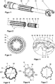
- FIGS 8 and 9 show a roller head 50 for producing the outer shaft described above.
- the roller head for producing the inner shaft described above has an analogous structure to the roller head 50 for producing the outer shaft.
- the roller head 50 has eight rollers 52 which are arranged in a star shape around a roller axis.
- the rollers 52 are each arranged at an angle of 45 ° to one another.
- Each roller 52 is supported by two bearing jaws 56.
- the two bearing jaws 56 of a roller 52 are connected to one another via a roller bearing foot 58.
- the roller bearing foot 58 has bores 59 for attachment to a frame of the roller head 50.
- a profile mandrel 60 can be seen, which is arranged in the middle of the eight rollers 52.
- a gap is provided between the profile mandrel 60 and the rollers 52, so that the profile mandrel 60 can be moved along the rolling axis without the rollers 52 rolling on the profile mandrel 60.
- the roller head can also have one, two, three, four, five, six, seven, nine, ten, eleven, twelve or more rollers 52 which are circumferentially spaced apart at a corresponding angle.
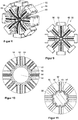
- FIG. 10 An enlarged view of the profile mandrel 60 can be seen, a gap being provided between the profile mandrel 60 and the rollers 52, which gap corresponds to the profile of a shaft to be produced by means of the rolling head 50.
- rollers 52 are profiled and have a roller center profile 53 and a roller edge profile 54.
- the diameter of the roller center profile 53 is larger than the diameter of the roller edge profile 54.
- the rollers 52 and the profile mandrel 60 are arranged with respect to one another such that a roller center profile 53 corresponds to a groove 62 of the profile mandrel 60.
- the roller edge profiles 54 correspond to the profile heads 64 of the profile mandrel 60.
- FIG 11 A cross-section of a detailed view of a rolling head 50 can be seen, the rollers 52 being in contact with an outer shaft 20 which is pushed onto the profile mandrel 60.
- the outer shaft 20 is cold rolled so that the outer shaft 20 takes on the profile of the profile mandrel 60 on its inner peripheral surface and is formed on its outer peripheral surface by the rollers 52 and in particular the roller profile.
- roller center profile 53 corresponds to the groove 52 of the profile mandrel
- the material of the outer shaft 20 is pressed into the groove 62 of the profile mandrel 60 by the roller center profile 53.
- the roller edge profiles 54 roll or roll on the profile heads 24 of the outer shaft 20, which intensifies the force acting on the rollers 52 on the outer shaft 20 and improves the internal toothing of the outer shaft 20 allows.
- the inner shaft of a steering shaft can also be manufactured by means of a roller head described.
- Figures 12 to 14 show the sequence of movements of a double stroke movement for profiling the outer shaft 20. These are cross-sectional views, each showing two opposing rollers 52, a profile mandrel 60 being arranged between the rollers 52, on which an outer shaft 20 is pushed.
- Figure 12 shows a preliminary stroke movement of the profile mandrel 60.
- the profile mandrel 60 is moved relative to the rollers 52. There is no contact between the profile mandrel 60 and the rollers 52, so that the rollers 52 remain in a rest position.
- the outer shaft 20 pushed onto the profile mandrel 60 is in Figure 12 not yet in contact with the rollers 52.
- the in Figure 14 return stroke movement shown.
- the profile mandrel 60 and the outer shaft 20 move together in relation to the forward stroke movement in the opposite direction. There is still contact between the outer shaft 20 and the rollers 52, so that the rollers 52 also rotate in the opposite direction during the return stroke movement.
- the return stroke movement can be maintained until the outer shaft 20 and the profile mandrel 60 have left the roller head 50.
- the return stroke movement can be followed by a new forward stroke movement, for example to improve the quality of the profile of the outer shaft.
- Figure 15 shows a sectional view of the outer shaft 20 and a roller 52, wherein the outer shaft 20 is relative to the roller 52 at a reversal point of the forward stroke movement to the return stroke movement.
- the grooves 22 have the groove length I.
- the roller 52 is continuously rolled along the groove length I from the free end of the shaft 20 to the end of the groove 22. Subsequently, the roller 52 is continuously rolled back from the reversal point at the end of the groove length I. In this way, the complex pipe geometry is created with a very simple rolling process.
Description
- Die vorliegende Erfindung betrifft ein Verfahren zum Herstellen einer profilierten Hohlwelle für eine teleskopierbare Lenkwelle eines Kraftfahrzeugs, umfassend das Bereitstellen einer zu bearbeitenden Hohlwelle sowie eines Profildorns und eines mindestens eine Rolle aufweisenden Rollierkopfes, wobei der Profildorn zur Erzeugung einer Nut in der Hohlwelle zunächst in die Hohlwelle eingeführt wird und im Anschluss die Hohlwelle relativ zu dem Rollierkopf bewegt wird.
- Teleskopierbare Lenkwellen in Kraftfahrzeugen ermöglichen zum einen eine Verstellbarkeit der Lenksäule, zum anderen sollen sie verhindern, dass sich die Lenkwelle im Fall eines Crashs weiter in das Innere der Fahrgastzelle verschiebt und zu Verletzungen der Insassen führt. Dies wird in der Regel durch die Bereitstellung zweier gegeneinander teleskopierbarer Wellen bzw. Hohlwellen erreicht, welche gemeinsam eine Lenkwelle bilden. Weiterhin kann durch die Teleskopierbarkeit eine Einstellung der Lenkradposition in Längsrichtung erreicht werden.
- Die Hohlwellen werden mit Profilen versehen, welche miteinander korrespondieren und zum einen eine Verschiebung in Längsrichtung und zum anderen eine Übertragung eines Drehmoments ermöglichen. Dabei müssen die Profile leichtgängig und spielfrei gegeneinander verschiebbar sein, wobei es insbesondere gilt, ein Verdreh- oder Knickspiel zu vermeiden.
- Aus der Anforderung einer exakten Drehmomentübertragung ergibt sich eine möglichst torsionssteife Auslegung der Hohlwellen. Entsprechend kommen herkömmlich Hohlwellen mit hohen Wandstärken zum Einsatz. Um die Profilierung, beispielsweise eine Längsverzahnung, in den Hohlwellen zu erzeugen, erfolgt in der Regel eine schrittweise Bearbeitung, wobei die Hohlwellen zunächst auf einen Profildorn geschoben werden. Formwerkzeuge, wie zum Beispiel Rollen, wirken dann auf die äußeren Umfangsflächen der Hohlwellen ein. Dadurch kann zum einen die Hohlwelle an das Profil des Profildorns angepasst werden, zum anderen kann auf der äußeren Umfangsoberfläche ein entsprechendes Profil erzeugt werden. Aufgrund der hohen Materialstärken der Hohlwellen und der damit verbundenen hohen Walzkräfte erfolgt die Profilierung der Hohlwellen in der Regel nur schrittweise, wobei es zum Fließen des Materials kommt. Dazu arbeiten sich die Formwerkzeuge in Längs- und Umfangsrichtung Schritt für Schritt über die Hohlwelle und erzeugen so die gewünschte Profilierung. Die Schrittweise Erzeugung der Profilierung der Hohlwellen führt zu hohen Zykluszeiten, welche die Herstellungskosten der profilierten Hohlwellen in die Höhe treiben.
- Die
CH 579427 A5 - Aus der
FR 1 331 015 A - Ausgehend von dem bekannten Stand der Technik ist es eine Aufgabe der vorliegenden Erfindung, ein verbessertes Verfahren zur Herstellung einer profilierten Hohlwelle für eine teleskopierbare Lenkwelle eines Kraftfahrzeugs bereitzustellen.
- Diese Aufgabe wird mittels eines Verfahrens mit den Merkmalen des Anspruchs 1 gelöst. Vorteilhafte Ausgestaltungen ergeben sich aus den Unteransprüchen.
- Entsprechend wird ein Verfahren zum Herstellen einer profilierten Hohlwelle für eine teleskopierbare Lenkwelle eines Kraftfahrzeugs angegeben, welches das Bereitstellen einer zu bearbeitenden Hohlwelle sowie eines Profildorns und eines mindestens eine Rolle aufweisenden Rollierkopfes umfasst, wobei der Profildorn zur Erzeugung einer Nut in der Hohlwelle zunächst in die Hohlwelle eingeführt wird und im Anschluss die Hohlwelle relativ zu dem Rollierkopf bewegt wird. Erfindungsgemäß erfolgt zur Ausbildung einer Nut eine Bewegung der Hohlwelle relativ zu dem Rollierkopf ausschließlich in Richtung der Längsachse der Hohlwelle.
- Da auf eine kontinuierliche Drehbewegung des Profildorns und der Hohlwelle relativ zu dem Rollierkopf verzichtet wird, bedarf es einer vergleichsweise geringen Bearbeitungszeit zur Ausbildung der Nut in der Hohlwelle. Insgesamt ergeben sich dadurch vergleichsweise geringe Taktzeiten zur Ausbildung der mindestens einen Nut in der Hohlwelle. Auch die Komplexität der Fertigung reduziert sich durch den Wegfall einer kontinuierlichen Drehbewegung der Hohlwelle relativ zum dem Rollierkopf während der Bearbeitung der Hohlwelle. Insbesondere ist keine aufwändige Koordinierung einer Rotationsbewegung und einer Axialbewegung der Hohlwelle relativ zu dem Rollierkopf mehr nötig.
- Die Rolle des Rollierkopfes weist bevorzugt einen definierten und, zumindest für den Produktionszyklus unveränderbaren radialen Abstand zu der Hohlwelle auf. Mit anderen Worten erfolgt keine Zustellung der Rolle bezogen auf den radialen Abstand zur Hohlwelle oder der Wert der Zustellung ist für die Dauer des jeweiligen Produktionsprozesses konstant. Die Hohlwelle umfasst eine äußere Umfangsoberfläche mit einem Außendurchmesser, wobei der radiale Abstand der Rolle geringer ist als der Außendurchmesser der Hohlwellen. Somit erfolgt bei der relativen Verschiebung der Hohlwelle zum Rollierkopf in Richtung der Längsachse, dass die Rolle auf die äußere Umfangsoberfläche der Hohlwelle so einwirkt, dass der Werkstoff der Hohlwelle verdrängt wird und dadurch die zumindest eine Nut in der Hohlwelle ausgebildet wird.
- Insgesamt ermöglicht das Verfahren eine vereinfachte Herstellung, insbesondere für Grobzahnformen an Hohlwellen. Da zur Ausbildung einer Nut in der Hohlwelle, die Hohlwelle lediglich in Richtung ihrer Längsachse relativ zu dem Rollierkopf bewegt werden muss, kann die Bearbeitung ohne weiteres im Kaltwalzverfahren erfolgen.
- In einer bevorzugten Ausführungsform wird der Profildorn mit der Hohlwelle gemeinsam bewegt und die Bewegung des Profildorns und der Hohlwelle relativ zu dem Rollierkopf ausschließlich in Richtung der Längsachse der Hohlwelle erfolgt.
- Durch das gemeinsame Bewegen des Profildorns und der Hohlwelle wird die vorhandene Reibung zwischen dem Profildorn und der Hohlwelle minimiert, da keine relative Verschiebung zwischen dem Profildorn und der Hohlwelle während des Einwirkens der Rolle des Rollierkopfes auf die Hohlwelle und der damit verbundenen Ausbildung der zumindest einen Nut stattfindet.
- In einer weiter bevorzugten Ausführungsform erfolgt die Erzeugung der mindestens einen Nut mit einer Nutlänge auf der Hohlwelle durch eine entlang der Nutlänge durchgehenden Vorhubbewegung der Hohlwelle relativ zu dem Rollierkopf, wobei die Rolle des Rollierkopfes auf der Hohlwelle in Längsrichtung abrollt.
- Unter der durchgehenden Vorhubbewegung wird eine relative Bewegung der Hohlwelle gegenüber des Rollierkopfes über die gesamte Nutlänge ohne eine Richtungsumkehr verstanden. Vorzugsweise erfolgt die Bewegung mit einer konstanten Geschwindigkeit oder mit einem definierten Geschwindigkeitsprofil.
- Wird die Nut auf der Hohlwelle durch eine durchgehende Vorhubbewegung erzeugt, ist es ausreichend, dass die Hohlwelle einmalig in Längsrichtung relativ zu dem Rollierkopf und insbesondere der Rolle des Rollierkopfes bewegt wird. Die Rolle wirkt dabei mit einer Kraft auf die Hohlwelle, um auf dieser die Nut auszubilden. Entsprechend kann die nötige Bearbeitungszeit zur Erzeugung einer Nut auf der Hohlwelle reduziert werden. Da die Rolle des Rollierkopfes lediglich in Richtung der Längsachse auf der Hohlwelle abrollt, liegt eine einfache Relativbewegung zwischen der Hohlwelle und dem Rollierkopf vor, welche keiner aufwändigen Koordinierung bedarf.
- Die Erzeugung mindestens einer Nut auf der Hohlwelle kann vorzugsweise durch eine Doppelhubbewegung der Hohlwelle relativ zu dem Rollierkopf erfolgen. Dies hat den Vorteil, dass keine zusätzlichen Bewegungen erforderlich sind, um die Hohlwelle samt dem Dorn vom Rollierkopf zu trennen beziehungsweise aus diesem heraus zu bewegen. Entsprechend wird die Hohlwelle gemeinsam mit dem Dorn durch eine Vorhubbewegung relativ zum Rollierkopf mit der Rolle des Rollierkopfes in Kontakt gebracht und eine Nut in Richtung der Längsache der Hohlwelle in der Hohlwelle erzeugt. Mit dem Erreichen der gewünschten Nutlänge endet die Vorhubbewegung. Anschließend erfolgt eine Rückhubbewegung, bei welcher sich die Hohlwelle gemeinsam mit dem Profildorn in entgegengesetzter Richtung der Vorhubbewegung relativ in Richtung der Längsachse der Hohlwelle bewegt. Während der Rückhubbewegung wird die während der Vorhubbewegung erzeugte Nut erneut durch die Rolle des Rollierkopfes gewalzt.
- In einer weiter bevorzugten Ausgestaltung wird abschließend die Hohlwelle relativ zu dem Rollierkopf zurückgezogen. Dadurch kann der Kontakt zwischen der Rolle des Rollierkopfes und der Hohlwelle getrennt werden. Entsprechend kann ein Walzvorgang zum Erzeugen einer Nut in der Hohlwelle abgeschlossen werden. Dies ist vor allem dann von Vorteil, wenn die Nutlänge geringer ist als die Länge der Hohlwelle oder mit anderen Worten, wenn die Nut nur teilweise auf der Hohlwelle ausgebildet ist.
- In einer weiter bevorzugten Weiterbildung erfolgt die Erzeugung aller in der Hohlwelle vorhandenen Nuten durch einen gemeinsamen Arbeitsschritt mit einer durchgehenden Vorhubbewegung.
- Vorzugsweise ist für jede erzeugte Nut auf der Hohlwelle eine separate Rolle in dem Rollierkopf bereitgestellt, wobei die Rollen zur Erzeugung der Nuten gleichzeitig auf der Hohlwelle abrollen.
- Auf diese Weise ist es möglich, mehrere Nuten in Richtung der Längsachse der Hohlwelle in der Hohlwelle auf einmal zu erzeugen.
- Dadurch kann mittels einer axialen Relativbewegung des Profildorns und der Hohlwelle gegenüber den Rollen des Rollierkopfes der gesamte Umformvorgang zur Erzeugung der Nuten in der Hohlwelle ausgeführt werden. Dadurch ergibt sich eine deutliche Zeitersparnis, so dass gegenüber herkömmlichen Herstellungsverfahren deutlich kürzere Taktzeiten zur Profilierung der Hohlwelle beziehungsweise zur Ausbildung der Nuten in der Hohlwelle möglich sind.
- Darüber hinaus kann eine gleichzeitige Ausbildung der in der Hohlwelle zu erzeugenden Nuten bei einer symmetrischen Anordnung der Nuten in der Hohlwelle zu einer im Wesentlichen symmetrischen Krafteinwirkung der Rollen des Rollierkopfes in radialer Richtung auf die Hohlwelle beziehungsweise den Profildorn führen. Dies ist besonders vorteilhaft für die Ausgestaltung des Rollierkopfes. So führt ein symmetrischer Kräfteverlauf dazu, dass geringere Anforderungen an die Stützwirkung der einzelnen Komponenten des Rollierkopfes bestehen. So reduziert der symmetrische Kräfteverlauf die in einer Lagerung des Rollierkopfes entstehenden Momente erheblich, was zu einer Reduktion der Konstruktions- und Fertigungskosten des Rollierkopfes führen kann.
- Ferner wirkt sich eine symmetrische Krafteinwirkung auch positiv auf die Eigenschaften der profilierten Hohlwelle aus. So erfährt die Hohlwelle gleichmäßige Biegevorgänge während der Kaltumformung, so dass auf der Hohlwelle gleichmäßige Nuten entstehen. Das Ergebnis ist ein symmetrischer Rotationskörper mit einer homogenen Materialverteilung.
- Die Bereitstellung einer separaten Rolle in dem Rollierkopf für jede zu erzeugende Nut in der Hohlwelle macht somit eine Rotationsbewegung des Profildorns und der Hohlwelle überflüssig. Dadurch kann zum einen die Bearbeitungszeit zur Erzeugung einer profilierten Hohlwelle und zum anderen die Komplexität des Verfahrens zum Herstellen der profilierten Hohlwelle reduziert werden.
Die vorliegende Erfindung wird auch durch ein Verfahren mit den Merkmalen des Anspruchs 6 gelöst. Vorteilhafte Ausgestaltungen ergeben sich aus dem Unteranspruch. - Entsprechend wird ein Verfahren zur Herstellung einer teleskopierbaren Lenkwelle für ein Kraftfahrzeug angegeben, wobei eine innere Hohlwelle mit ihrem Nutenprofil in eine äußere Hohlwelle mit einem Nutenprofil eingeführt wird, wobei mittels zumindest einer Rolle in einer durchgehenden Vorhubbewegung entlang der Längsachse der Lenkwelle das Nutenprofil der äußeren Hohlwelle auf das Nutenprofil der inneren Hohlwelle kalibriert wird.
- Dadurch, dass Rollen auf das Nutenprofil der äußeren Hohlwelle einwirken, erfolgt das Anschmiegen des Nutenprofils der äußeren Hohlwelle an das Nutenprofil der innere Hohlwelle. Durch das Anschmiegen wird das vorhandene Spiel zwischen der inneren und äußeren Hohlwelle minimiert, sodass eine spielarme und leichtgängig teleskopierbare Lenkwelle bereitgestellt werden kann.
- Darüber hinaus kann vorzugsweise in die innere Hohlwelle ein Profildorn eingeführt sein, wobei der Profildorn der inneren Abstützung dient und somit einer ungewollten Verformung der inneren und äußeren Hohlwelle entgegenwirkt. Weiterhin ist es denkbar und möglich, dass während die zumindest eine Rolle die Nuten der äußeren Hohlwelle kalibriert, die innere und äußere Hohlwelle gegeneinander in ihrer Längsrichtung teleskopiert werden. Dies kann vorzugsweise oszillierend erfolgen, sodass eine Hin- und Herbewegung vollführt wird. Versuche haben ergeben, dass diese oszillierende Bewegung eine weitere Spielminimierung zur Folge hat. Weiterhin hat sich gezeigt, dass ein zwischen der inneren Hohlwelle und äußeren Hohlwelle vorhandener Schmierstoff optimal verteilt wird.
- In einer weiter bevorzugten Weiterbildung wird vor dem Einführen der inneren Hohlwelle in die äußere Hohlwelle auf die innere Hohlwelle eine Kunststoffhülse aufgebracht, die nach dem Einführen der Hohlwelle zwischen den Hohlwellen angeordnet ist, wobei die drei Bauteile zueinander kalibriert werden.
- Die Kunststoffhülse ermöglicht bessere Gleiteigenschaften während dem Teleskopieren der Lenkwelle. Durch das Kalibrieren der drei Bauteile zueinander kann auf Grund der Spielreduktion im Nutenprofil der äußeren Hohlwelle eine besonders spielarme und torsionssteife Lenkwelle bereitgestellt werden.
Die vorliegende Erfindung wird auch durch eine Lenkwelle mit den Merkmalen des Anspruchs 8 gelöst. Vorteilhafte Ausgestaltungen ergeben sich aus den Unteransprüchen. - Entsprechend wird eine Lenkwelle für ein Kraftfahrzeug angegeben, welche eine innere Welle und eine äußere Welle umfasst, welche koaxial zueinander angeordnet und gegeneinander teleskopierbar sind, wobei die innere Welle und die äußere Welle ein Profil aus miteinander korrespondierenden Nuten aufweisen. Erfindungsgemäß ist zumindest eine der beiden Wellen der Lenkwelle nach dem oben genannten Verfahren hergestellt.
- Entsprechend ist es möglich, eine Lenkwelle für ein Kraftfahrzeug herzustellen, welche sich durch geringere Taktzeiten und eine kostengünstigere Fertigung auszeichnet. Beispielsweise kann diese Lenkwelle als eine Lenkzwischenwelle, wobei diese Lenkzwischenwelle zumindest ein Universalgelenk umfasst, oder als Lenkspindel, wobei eine solche Lenkspindel drehbar in einer Lenksäule gelagert ist und einen Kopplungsabschnitt zur Anbindung eines Lenkrades umfasst, ausgebildet sein.
- In einer bevorzugten Ausführungsform beträgt ein Flankenwinkel α der Nuten in der äußeren Welle und/oder der inneren Welle und der Flankenwinkel α eines Profilkopfes einer Innenverzahnung der äußeren Welle und/oder der inneren Welle 45° bis 75°, bevorzugt 55° bis 65° und besonders bevorzugt 60°.
- Der Winkel α entspricht dem Winkel der beiden Zahnflanken eines Zahns einer Innenverzahnung der äußeren Welle. Den gleichen Winkel α weisen zwei sich gegenüberliegende Zahnflanken einer Außenverzahnung der inneren Welle auf. Die sich gegenüberliegenden Zahnflanken bilden dabei zugleich die Seitenwände einer in der inneren Welle erzeugten Nut. Dadurch ist es möglich, dass ein Zahn der Innenverzahnung der äußeren Welle mit einer Nut der Außenverzahnung der inneren Welle korrespondiert. Ein Flankenwinkel α von 45° bis 75° ermöglicht, dass die innere Welle und die äußere Welle formschlüssig zur Drehmomentübertragung in Eingriff gebracht werden können und gleichzeitig in Richtung der Längsachse der Lenkwelle verschiebbar sind. Der Flankenwinkel α von 45° bis 75° ermöglicht ferner, dass die innere Welle und die äußere Welle untereinander auf die Lenkwelle wirkende Torsionskräfte übertragen können und gleichzeitigt die Gefahr eines Verkeilens der inneren Welle mit der äußeren Welle auf Grund der Rückfederung der Flanken, was zu einer Beeinträchtigung der Verschiebbarkeit zueinander in Längsrichtung führen kann, gering gehalten ist. Untersuchungen haben ergeben, dass ein bevorzugter Flankenwinkel α von 55° bis 65° verbesserte Ergebnisse in Bezug auf Toleranzanfälligkeit der zueinander teleskopierbaren inneren und äußeren Welle und der Torsionssteifigkeit liefert. Als optimaler Flankenwinkel α wurde ein Winkel mit dem Wert von 60°ermittelt. Dieser optimale Flankenwinkel zeigte ein geringes Spiel zwischen der inneren und äußeren Welle und eine hohe Torsionssteifigkeit.
- In einer weiteren Ausführungsform liegt das Verhältnis der Differenz eines Innendurchmessers eines Profilkopfes einer Außenverzahnung und eines Innendurchmessers eines Nutbodens einer Innenverzahnung der inneren Welle und/oder der äußeren Welle zu einer Materialstärke der inneren Welle und/oder der äußeren Welle zwischen 1 und 4.
- Versuche haben ergeben, dass das Verhältnis bevorzugt zwischen 1,5 und 3,5 liegt und besonders bevorzugt zwischen 2 und 3, da so ideale Bedingungen für die Einbringung der Nuten nach dem oben genannten Verfahren vorliegen.
- Damit die Lenkwelle ein erforderliches Mindestmaß an Torsionssteifigkeit bereitstellen kann, sollte eine minimale Wandstärke der inneren Welle und/oder der äußeren Welle, welche 25% der Differenz des Innendurchmessers eines Zahns der Außenverzahnung und des Innendurchmessers eines Zahns der Innenverzahnung der inneren Welle und/oder der äußeren Welle beträgt, nicht unterschritten werden.
- In einer bevorzugten Weiterbildung weist die innere Welle und/oder die äußere Welle vor dem Einbringen der zumindest einen Nut ein zu mindestens teilweises, bezogen auf die Wellenlängsachse, kreiszylindrisches oder ein polygonales Hohlquerschnittsprofil auf.
- Zur Erreichung einer sicheren Drehmomentenübertragung im Missbrauchsfall ist der Hohlquerschnitt bevorzugt ein Dreiflach oder Vierflach.
- In einer bevorzugten Weiterbildung ist zwischen der inneren Welle und der äußeren Welle eine Hülse mit einem Profil angeordnet, welches mit dem Profil der inneren Welle und dem Profil der äußeren Welle korrespondiert.
- Die Hülse trägt dazu bei, dass das Spiel zwischen den Kontaktflächen der inneren Welle und der äußeren Welle reduziert beziehungsweise verhindert werden kann. Darüber hinaus kann die Hülse eine leichtgängige Bewegung der inneren Welle relativ zur äußeren Welle ermöglichen. Entsprechend kann die Hülse ermöglichen, dass eine Justierung der Lenkwelle auf einem geringen und konstanten Kraftniveau erfolgt.
- In einer weiter bevorzugten Ausgestaltung ist die Hülse aus Kunststoff gefertigt. Dadurch ist es möglich, auf einfachem und schnellem Wege das Innenprofil der Hülse und das Außenprofil der Hülse an das Profil der Innenwelle und der Außenwelle exakt anzupassen, um eine Längsverschiebung der Lenkwelle mit einem definierten Kraftniveau zu erreichen Ferner ermöglicht eine Hülse aus Kunststoff eine Reduktion der Geräuschbildung beim Einsatz der Lenkwelle.
- Bevorzugte weitere Ausführungsformen und Aspekte der vorliegenden Erfindung werden durch die nachfolgende Beschreibung der Figuren näher erläutert. Dabei zeigen:
- Figur 1
- schematisch eine perspektivische Ansicht einer Lenkwelle;
- Figur 2
- schematisch einen Teil einer äußeren Welle und einen Teil einer inneren Welle der vorstehenden Figur;
- Figur 3
- schematisch eine Querschnittansicht der Lenkwelle der vorstehenden Figuren;
- Figur 4
- schematisch eine Detailansicht der in
Figur 3 gezeigten Querschnittansicht; - Figur 5
- schematisch eine Querschnittansicht einer äußeren Welle;
- Figur 6
- schematisch eine Querschnittansicht einer inneren Welle;
- Figur 7
- schematisch eine Querschnittansicht einer Hülse;
- Figur 8
- schematisch eine perspektivische Ansicht eines Rollierkopfes;
- Figur 9
- schematisch eine Draufsicht des Rollierkopfes der vorstehenden Figur;
- Figur 10
- schematisch eine Detailansicht der in
Figur 9 gezeigten Draufsicht des Rollierkopfes; - Figur 11
- schematisch eine Schnittansicht der Detailansicht des Rollierkopfes der vorstehenden Figur;
- Figur 12
- schematisch eine Schnittansicht durch den Rollierkopf der vorstehenden Figuren, wobei der Schnitt entlang der Längsachse eines Profildorns verläuft;
- Figur 13
- schematisch eine Schnittansicht des Rollierkopfes der vorstehenden Figuren, wobei sich eine Hohlwelle im Rollierkopf befindet;
- Figur 14
- schematisch eine Schnittansicht des Rollierkopfes der vorstehenden Figuren, wobei sich eine Hohlwelle in dem Rollierkopf befindet; und
- Figur 15
- schematisch eine Schnittansicht einer Hohlwelle, welche mit einer Rolle des Rollierkopfes in Kontakt steht.
- Im Folgenden werden bevorzugte Ausführungsbeispiele anhand der Figuren beschrieben. Dabei werden gleiche, ähnliche oder gleichwirkende Elemente mit identischen Bezugszeichen bezeichnet. Um Redundanzen zu vermeiden, wird auf eine wiederholte Beschreibung dieser Elemente in der nachfolgenden Beschreibung teilweise verzichtet.
-
Figur 1 ist eine Lenkwelle 10 für ein Kraftfahrzeug zu entnehmen. Die Lenkwelle 10 weist eine äußere Welle 20 und eine innere Welle 30 auf, welche gegeneinander teleskopierbar sind. An einem äußeren Ende weist die äußere Welle 20 Gabel 21 auf, die ein Teil eines nicht gezeigten Universalgelenks darstellt, um die Lenkwelle 10 in einem Lenkstrang zu integrieren. Auch die innere Welle 30 weist an einem äußeren Ende eine Gabel 31 auf, die ein Teil eines nicht gezeigten Universalgelenks darstellt, um die Lenkwelle 10 in den Lenkstrang zu integrieren. - Die äußere Welle 20 und die innere Welle 30 sind Hohlwellen, welche aus einem Stahl mit guten Umformeigenschaften gefertigt sind. Alternativ können die äußere Welle 20 und die innere Welle 30 auch aus Aluminiumlegierungen, Edelstahl und dergleichen gefertigt sein.
-
Figuren 1 und 2 ist zu entnehmen, dass die äußere Welle 20 in dem Bereich, welcher zur Aufnahme der inneren Welle 30 dient, profiliert ist. Entsprechend weist die äußere Welle 20 in diesem Bereich Nuten 22 auf, welche in Axialrichtung der äußeren Welle 20 verlaufen. Die Nuten 22 mit einer Nutlänge I auf der äußeren Umfangsoberfläche 27 der äußeren Welle 20 bilden eine Innenverzahnung auf der inneren Umfangsoberfläche 28 der äußeren Welle 20.Figur 2 ist zu entnehmen, dass ein Endabschnitt der inneren Welle 30, welcher in einem Betriebszustand in die äußere Welle 20 gesteckt ist, eine Außenverzahnung aufweist, welche mit der Innenverzahnung der äußeren Welle 20 korrespondiert. Die Außenverzahnung der inneren Welle 30 ist durch Nuten 32 auf einer äußeren Umfangsoberfläche 37 der inneren Welle 30 gebildet. Auf der Außenverzahnung der inneren Welle 30 ist eine Hülse 40 angeordnet, welche sowohl mit der Außenverzahnung der inneren Welle 30 als auch mit der Innenverzahnung der äußeren Welle 20 korrespondiert. Die Hülse 40 ist dabei auf die innere Welle 30 pressgepasst, so dass sich die Hülse 40 gemeinsam mit der inneren Welle 30 relativ zu der äußeren Welle 20 in dieser bewegen kann. In einer nicht dargestellten Ausführungsform ist die Hülse 40 auf der inneren Welle 30 durch eine Verstemmung axial fixiert. Um den Steifigkeitsanforderungen der Lenkwelle 10 gerecht zu werden, besteht zwischen der inneren Welle 30 beziehungsweise der Hülse 40 und der äußeren Welle 20 ein sehr geringes Spiel, das quasi als Spielfrei bezeichnet werden kann. Vielmehr wird zwischen der inneren Welle 30 beziehungsweise der Hülse 40 und der äußeren Welle 20 ein Schiebesitz bereitgestellt, welcher eine Justierung der Länge der Lenkwelle 10 auf einem sehr geringen und konstanten Kraftniveau erlaubt. -
Figuren 3 und 4 sind Querschnittansichten durch die Lenkwelle 10 zu entnehmen. Es ist zu erkennen, dass das Profil der äußeren Welle 20 mit dem Profil der Hülse 40 beziehungsweise der inneren Welle 30 korrespondiert. So trifft beispielsweise die Nut 22 der äußeren Welle 20 auf die Nut 42 der Hülse 40 beziehungsweise die Nut 32 der inneren Welle 30. Die jeweils an die Nuten 22, 42, 32 angrenzenden Flanken 26, 46, 36 erstrecken sich, wie in denFiguren 5 und 6 gezeigt, von dem Nutboden jeweils im gleichen Winkel. Daraus ergibt sich, wie inFigur 4 gezeigt, dass die Flanken 26, 36, 46 der äußeren Welle, der Hülse und der inneren Welle nahezu parallel zueinander verlaufen und der Kraftfluss zwischen der inneren Welle 30 und der äußeren Welle 20 lediglich über die Flanken 26, 36, 46 stattfindet. Im Bereich außerhalb der Flanken 26, 36, 46 besteht kein kraftübertragender Kontakt zwischen der inneren Welle 30, der Hülse 40 und der äußeren Welle 20. - Den
Figuren 3 und 4 ist weiterhin zu entnehmen, dass an eine innere Umfangsoberfläche des Profilkopfs 24 der äußeren Welle 20 ein Profilkopf 44 der Hülse 40 angrenzt. An die innere Umfangsoberfläche des Profilkopfs 44 grenzt wiederum ein Profilkopf 34 der inneren Welle 30 an. - Aufgrund der miteinander korrespondierenden Profile der äußeren Welle 20, der Hülse 40 und der inneren Welle 30 steht die äußere Welle 20 mit der inneren Welle 30 indirekt über die Hülse 40 im Eingriff. Somit ist es möglich, dass zwischen der äußeren Welle 20 und der inneren Welle 30 eine Drehmomentenübertragung bereitgestellt werden kann.
- Die
Figuren 5, 6 und 7 zeigen gesondert die Profilquerschnitte der äußeren Welle 20, der inneren Welle 30 und der Hülse 40. Dabei istFigur 5 und 6 ein Innendurchmesser der Profilköpfe D1, ein Innendurchmesser der Nuten D2 sowie ein Flankenwinkel α zu entnehmen. Um ein Mindestmaß an Torsionssteifigkeit bereitzustellen, sollte das Verhältnis von der Differenz des Innendurchmessers der Profilköpfe D1 und des Innendurchmessers der Nuten D2 zu einer Materialstärke b zwischen 1 und 4, bevorzugt zwischen 1,5 und 3,5 und besonders bevorzugt zwischen 2 und 3 sein. -
Figuren 8 und 9 zeigen einen Rollierkopf 50 zur Herstellung der oben beschriebenen äußeren Welle. Der Rollierkopf zur Herstellung der oben beschriebenen inneren Welle weist einen analogen Aufbau zu dem Rollierkopf 50 zur Herstellung der äußeren Welle auf. Der Rollierkopf 50 weist acht Rollen 52 auf, welche sternförmig um eine Rollierachse herum angeordnet sind. Die Rollen 52 sind zueinander jeweils unter einem Winkel von 45° angeordnet. Jede Rolle 52 ist durch zwei Lagerbacken 56 gelagert. Die beiden Lagerbacken 56 einer Rolle 52 sind über einen Rollenlagerfuß 58 miteinander verbunden. - Der Rollenlagerfuß 58 weist Bohrungen 59 zur Befestigung an einem Rahmen des Rollierkopfes 50 auf.
- Den
Figuren 8 und 9 ist ein Profildorn 60 zu entnehmen, welcher inmitten der acht Rollen 52 angeordnet ist. Zwischen dem Profildorn 60 und den Rollen 52 ist ein Spalt bereitgestellt, so dass der Profildorn 60 entlang der Rollierachse bewegt werden kann, ohne dass die Rollen 52 auf dem Profildorn 60 abrollen. - Alternativ kann der Rollierkopf auch ein, zwei, drei, vier, fünf, sechs, sieben, neun, zehn, elf, zwölf oder mehr Rolle 52 aufweisen, welche unter einem entsprechenden Winkel voneinander beabstandet, umlaufend angeordnet sind.
-
Figur 10 ist eine vergrößerte Ansicht des Profildorns 60 zu entnehmen, wobei zwischen dem Profildorn 60 und den Rollen 52 ein Spalt bereitgestellt ist, welcher dem Profil einer mittels des Rollierkopfes 50 herzustellenden Welle entspricht. - Den
Figuren 10 und 11 ist zu entnehmen, dass die Rollen 52 profiliert sind und ein Rollenmittenprofil 53 sowie ein Rollenrandprofil 54 aufweisen. Dabei ist der Durchmesser des Rollenmittenprofils 53 größer als der Durchmesser des Rollenrandprofils 54. Die Rollen 52 und der Profildorn 60 sind derart zueinander angeordnet, dass ein Rollenmittenprofil 53 mit einer Nut 62 des Profildorns 60 korrespondiert. Ferner korrespondieren die Rollenrandprofile 54 mit den Profilköpfen 64 des Profildorns 60. -
Figur 11 ist ein Querschnitt einer Detailansicht eines Rollierkopfes 50 zu entnehmen, wobei die Rollen 52 mit einer äußeren Welle 20 in Kontakt stehen, welche auf den Profildorn 60 aufgeschoben ist. Dabei wird die äußere Welle 20 kaltgewalzt, so dass die äußere Welle 20 auf ihrer inneren Umfangsoberfläche das Profil des Profildorns 60 annimmt und auf ihrer äußeren Umfangsoberfläche durch die Rollen 52 und insbesondere das Rollenprofil, umgeformt wird. - Da das Rollenmittelprofil 53 mit der Nut 52 des Profildorns korrespondiert, wird das Material der äußeren Welle 20 durch das Rollenmittelprofil 53 in die Nut 62 des Profildorns 60 hineingedrückt. Auf den Profilköpfen 24 der äußeren Welle 20 rollen beziehungsweise walzen die Rollenrandprofile 54 ab, was eine Intensivierung der Krafteinwirkung der Rollen 52 auf die äußere Welle 20 und eine verbesserte Ausbildung der Innenverzahnung der äußeren Welle 20 ermöglicht. Alternativ kann auch die innere Welle einer Lenkwelle mittels eines beschriebenen Rollierkopfes gefertigt werden.
-
Figuren 12 bis 14 zeigen den Bewegungsablauf einer Doppelhubbewegung zur Profilierung der äußeren Welle 20. Dabei handelt es sich um Querschnittansichten, welche jeweils zwei gegenüberliegende Rollen 52 zeigen, wobei zwischen den Rollen 52 ein Profildorn 60 angeordnet ist, auf welchen eine äußere Welle 20 geschoben ist. -
Figur 12 zeigt eine Vorhubbewegung des Profildorns 60. Der Profildorn 60 wird relativ zu den Rollen 52 bewegt. Zwischen dem Profildorn 60 und den Rollen 52 besteht kein Kontakt, so dass die Rollen 52 in einer Ruheposition verweilen. Die auf den Profildorn 60 aufgeschobene äußere Welle 20 steht inFigur 12 noch nicht mit den Rollen 52 in Kontakt. - In
Figur 13 ist der Profildorn 60 mitsamt der äußeren Welle 20 nach wie vor in der Vorhubbewegung, mit dem Unterschied, dass nun die äußere Welle 20 mit den Rollen 52 in Kontakt steht. Der Spalt zwischen dem Profildorn 60 und den Rollen 52 ist nun von der äußeren Welle 20 ausgefüllt. Durch die Vorhubbewegung des Profildorns 60 gemeinsam mit der äußeren Welle 20 werden die Rollen 52 in Rotation versetzt. Sie walzen auf der äußeren Umfangsoberfläche der äußeren Welle 20 ab, wodurch die äußere Welle 20 die oben beschriebene Profilierung erfährt, da die Rollen 52 im Rollenmittelprofil 53 einen geringeren Abstand zum Profildorn 60 aufweisen als die noch nicht umgeformte äußere Welle 20. - Ist die gewünschte Länge der Profilierung und die damit verbundene Nutenlänge I der äußeren Welle 20 erreicht, setzt die in
Figur 14 gezeigte Rückhubbewegung ein. Der Profildorn 60 und die äußere Welle 20 bewegen sich dabei gemeinsam in Bezug auf die Vorhubbewegung in entgegengesetzte Richtung. Zwischen der äußeren Welle 20 und den Rollen 52 besteht nach wie vor Kontakt, so dass während der Rückhubbewegung auch die Rollen 52 in entgegengesetzte Richtung rotieren. Die Rückhubbewegung kann solange aufrechterhalten werden, bis die äußere Welle 20 und der Profildorn 60 den Rollierkopf 50 verlassen haben. Alternativ kann sich an die Rückhubbewegung eine erneute Vorhubbewegung anschließen, um beispielsweise die Güte der Profilierung der äußeren Welle zu verbessern. Zur Verbesserung des Abrollens der Rollen auf der zu profilierenden Welle und zur Minimierung von Fressen in den Kontaktflächen ist es denkbar und möglich, die Rollen oder die Welle auf der entsprechenden Kontaktfläche mit einem Schmierstoff zu benetzen -
Figur 15 zeigt eine Schnittansicht der äußeren Welle 20 und einer Rolle 52, wobei sich die äußere Welle 20 relativ zu der Rolle 52 an einem Umkehrpunkt der Vorhubbewegung zur Rückhubbewegung befindet. Die Nuten 22 weisen dabei die Nutenlänge I auf. Im Beispiel wird die Rolle 52 entlang der Nutlänge I durchgehend vom freien Ende der Welle 20 bis ans Ende der Nut 22 gerollt. Anschließend wird die Rolle 52 vom Umkehrpunkt am Ende der Nutlänge I durchgehend zurück gerollt. Auf diese Weise entsteht mit einem sehr einfachen Rollprozess die komplexe Rohrgeometrie. -
- 10
- Lenkwelle
- 20
- Äußere Welle
- 21
- Gabel
- 22
- Nut
- 24
- Profilkopf
- 26
- Flanke
- 27
- Äußere Umfangsoberfläche
- 28
- Innere Umfangsoberfläche
- 30
- Innere Welle
- 31
- Gabel
- 32
- Nut
- 34
- Profilkopf
- 36
- Flanke
- 37
- Äußere Umfangsoberfläche
- 40
- Hülse
- 42
- Nut
- 44
- Profilkopf
- 46
- Flanke
- 50
- Rollierkopf
- 52
- Rolle
- 53
- Rollenmittenprofil
- 54
- Rollenrandprofil
- 56
- Rollenlagerbacke
- 58
- Rollenlagerfuß
- 60
- Profildorn
- 62
- Nut
- 64
- Profilkopf
- 66
- Flanke
- D1
- Innendurchmesser eines Profilkopfes
- D2
- Innendurchmesser eines Nutbodens
- b
- Materialstärke
- α
- Flankenwinkel
- l
- Nutlänge
Claims (7)
- Verfahren zum Herstellen einer profilierten Hohlwelle für eine teleskopierbare Lenkwelle (10) eines Kraftfahrzeugs, umfassend das Bereitstellen einer zu bearbeitenden Hohlwelle sowie eines Profildorns (60) und eines mindestens eine Rolle (52) aufweisenden Rollierkopfes (50), wobei der Profildorn (60) zur Erzeugung einer Nut (22, 32) in der Hohlwelle zunächst in die Hohlwelle eingeführt wird und im Anschluss die Hohlwelle relativ zu dem Rollierkopf (50) bewegt wird, dadurch gekennzeichnet, dass
zur Ausbildung einer Nut (22, 32) eine Bewegung der Hohlwelle relativ zu dem Rollierkopf (50) ausschließlich in Richtung der Längsachse der Hohlwelle erfolgt. - Verfahren gemäß Anspruch 1, dadurch gekennzeichnet, dass der Profildorn (60) mit der Hohlwelle gemeinsam bewegt wird und die Bewegung des Profildorns (60) und der Hohlwelle relativ zu dem Rollierkopf (50) ausschließlich in Richtung der Längsachse der Hohlwelle erfolgt.
- Verfahren gemäß einem der vorhergehenden Ansprüche, dadurch gekennzeichnet, dass die Erzeugung der mindestens einen Nut (22, 32) mit einer Nutlänge (I) auf der Hohlwelle durch eine entlang der Nutlänge (I) durchgehenden Vorhubbewegung der Hohlwelle relativ zu dem Rollierkopf (50) erfolgt, wobei die Rolle (52) des Rollierkopfes (50) auf der Hohlwelle in Längsrichtung abrollt.
- Verfahren gemäß einem der vorhergehenden Ansprüche, dadurch gekennzeichnet, dass abschließend die Hohlwelle relativ zu dem Rollierkopf (50) zurückgezogen wird.
- Verfahren gemäß einem der vorhergehenden Ansprüche, dadurch gekennzeichnet, dass das Erzeugen aller in der Hohlwelle vorhandenen Nuten (22, 24, 32, 34) in einem gemeinsamen Arbeitsschritt mit einer durchgehenden Vorhubbewegung erfolgt..
- Verfahren zur Herstellung einer teleskopierbaren Lenkwelle (10) für ein Kraftfahrzeug, dadurch gekennzeichnet, dass eine innere Hohlwelle mit ihrem Nutenprofil in eine äußere Hohlwelle mit einem Nutenprofil eingeführt wird, wobei mittels zumindest einer Rolle (50) in einer durchgehenden Vorhubbewegung entlang der Längsachse der Lenkwelle das Nutenprofil der äußeren Hohlwelle auf das Nutenprofil der inneren Hohlwelle kalibriert wird.
- Verfahren nach Anspruch 6, dadurch gekennzeichnet, dass vor dem Einführen der inneren Hohlwelle in die äußere Hohlwelle auf die innere Hohlwelle eine Kunststoffhülse aufgebracht wird, die nach dem Einführen der Hohlwelle zwischen den Hohlwellen angeordnet ist, wobei die drei Bauteile zueinander kalibriert werden.
Applications Claiming Priority (2)
| Application Number | Priority Date | Filing Date | Title |
|---|---|---|---|
| DE102014115140 | 2014-10-17 | ||
| PCT/EP2015/067613 WO2016058723A1 (de) | 2014-10-17 | 2015-07-31 | Lenkwelle und verfahren zum herstellen einer profilierten hohlwelle für eine teleskopierbare lenkwelle eines kraftfahrzeugs |
Publications (2)
| Publication Number | Publication Date |
|---|---|
| EP3206811A1 EP3206811A1 (de) | 2017-08-23 |
| EP3206811B1 true EP3206811B1 (de) | 2020-04-22 |
Family
ID=53783710
Family Applications (1)
| Application Number | Title | Priority Date | Filing Date |
|---|---|---|---|
| EP15747433.9A Active EP3206811B1 (de) | 2014-10-17 | 2015-07-31 | Verfahren zum herstellen einer profilierten hohlwelle für eine teleskopierbare lenkwelle eines kraftfahrzeugs |
Country Status (5)
| Country | Link |
|---|---|
| US (1) | US10948008B2 (de) |
| EP (1) | EP3206811B1 (de) |
| CN (1) | CN107074265A (de) |
| ES (1) | ES2805098T3 (de) |
| WO (1) | WO2016058723A1 (de) |
Families Citing this family (14)
| Publication number | Priority date | Publication date | Assignee | Title |
|---|---|---|---|---|
| DE102016114970A1 (de) | 2016-08-11 | 2018-02-15 | Thyssenkrupp Ag | Lenkwelle für ein Kraftfahrzeug |
| DE102016215023B4 (de) * | 2016-08-11 | 2023-02-02 | Thyssenkrupp Ag | Verfahren zur Herstellung einer längenveränderbaren Lenkwelle und längenveränderbare Lenkwelle |
| CN108246941A (zh) * | 2016-12-29 | 2018-07-06 | 财团法人金属工业研究发展中心 | 齿轮的成型装置及其制造方法 |
| DE102017114534A1 (de) | 2017-06-29 | 2019-01-03 | Thyssenkrupp Ag | Lenkwelle für ein Kraftfahrzeug und Verfahren zum Herstellen |
| FR3070459B1 (fr) * | 2017-08-30 | 2020-02-21 | Robert Bosch Automotive Steering Vendome | Arbre intermediaire telescopique pour transmission de direction et son procede de fabrication |
| US11009078B2 (en) * | 2018-04-24 | 2021-05-18 | Textron Innovations Inc. | Compressible driveshaft |
| KR102174259B1 (ko) * | 2018-09-28 | 2020-11-04 | 일진제강(주) | 업세팅 공법을 이용한 중공 드라이브 샤프트 및 이의 제조 방법 |
| DE102018127098B3 (de) * | 2018-10-30 | 2019-11-21 | Thyssenkrupp Ag | Lenkwelle für eine Lenksäule eines Kraftfahrzeugs und Lenksäule für ein Kraftfahrzeug |
| DE102019207525A1 (de) * | 2019-05-22 | 2020-11-26 | Thyssenkrupp Ag | Lenksäule für ein Kraftfahrzeug |
| US11591003B2 (en) | 2020-10-01 | 2023-02-28 | Thyssenkrupp Presta Ag | Stowable steering column |
| US11318981B1 (en) | 2020-10-29 | 2022-05-03 | Thyssenkrupp Presta Ag | Stowable steering column |
| CN112588859A (zh) * | 2020-11-30 | 2021-04-02 | 思睿观通科技(江苏)有限公司 | 一种金属制品成型设备 |
| CN114810845A (zh) * | 2022-04-28 | 2022-07-29 | 洛阳轴承研究所有限公司 | 一种可实现传动侧向间隙自消除的花键传动装置 |
| CN115013451A (zh) * | 2022-06-27 | 2022-09-06 | 诸暨市双普机械有限公司 | 一种用于座驾式抹光机的万向连轴器 |
Family Cites Families (38)
| Publication number | Priority date | Publication date | Assignee | Title |
|---|---|---|---|---|
| US10569A (en) * | 1854-02-28 | jackson | ||
| US1605828A (en) * | 1926-11-02 | Pluting machine | ||
| US531170A (en) * | 1894-12-18 | Emil h | ||
| US473020A (en) * | 1892-04-19 | Method of corrugating pipes | ||
| US14551A (en) * | 1856-04-01 | Seamless metal tubes | ||
| US838569A (en) * | 1906-05-21 | 1906-12-18 | Isaac W Numan | Corrugating-machine. |
| US890526A (en) * | 1906-12-18 | 1908-06-09 | Union Metal Post Company | Corrugating-machine. |
| US1638481A (en) * | 1926-09-09 | 1927-08-09 | Union Metal Mfg Co | Fluting machine |
| US2367226A (en) * | 1940-05-10 | 1945-01-16 | Foster Wheeler Corp | Apparatus for producing extended surface tubular members |
| GB914329A (de) | 1958-01-13 | |||
| FR1331015A (fr) * | 1962-08-03 | 1963-06-28 | élément tubulaire de transmission à cannelures axiales et son procédé d'exécution | |
| US3330145A (en) * | 1964-10-05 | 1967-07-11 | Straza Ind | Machine and method for tapering rodlike tubular workpieces |
| GB1142837A (en) | 1966-11-09 | 1969-02-12 | Exnii Metallorezh Stankov | Improvements in or relating to pressure heads |
| JPS4834663B1 (de) | 1968-06-26 | 1973-10-23 | ||
| DE2017709A1 (de) * | 1970-04-14 | 1971-11-04 | Zahnradfabrik Friedrichshafen Ag, 7990 Friedrichshafen | Werkzeug zum Einrollen von Längsnuten in zylindrische Werkstücke |
| CH579427A5 (de) | 1975-02-24 | 1976-09-15 | Grob Ernst Fa | |
| IT1129074B (it) | 1980-04-16 | 1986-06-04 | Metalli Ind Spa | Apparecchiatura per formare a punta l estremita di un tubo metallico mediante un operazione di trafilatura |
| JPS577317A (en) * | 1980-06-17 | 1982-01-14 | Sumitomo Light Metal Ind Ltd | Manufacture of grooved pipe |
| AT372314B (de) * | 1981-07-03 | 1983-09-26 | Supervis Ets | Lenkspindel fuer lenkvorrichtungen bei kraftfahrzeugen |
| JPS5835023A (ja) | 1981-08-26 | 1983-03-01 | Masaru Onishi | 管材の溝部形成方法 |
| GB8605769D0 (en) | 1986-03-08 | 1986-04-16 | Brd Co Ltd | Propeller shaft for motor vehicle |
| CH675840A5 (de) * | 1988-10-05 | 1990-11-15 | Grob Ernst Fa | |
| US4995252A (en) * | 1989-03-06 | 1991-02-26 | Carrier Corporation | Method and apparatus for internally enhancing heat exchanger tubing |
| US5231859A (en) * | 1992-03-03 | 1993-08-03 | Trimble House Corporation | Fluting machine |
| US5765419A (en) * | 1994-06-25 | 1998-06-16 | Ernst Grob Ag | Method and apparatus for a rolling of hollow articles |
| JPH10314837A (ja) | 1997-03-12 | 1998-12-02 | Nisshin Steel Co Ltd | 螺旋状異形管及びその成形方法並びに成形装置 |
| JPH1190510A (ja) * | 1997-09-19 | 1999-04-06 | Plant Engineering Yoshida Kinen Kk | 線材の圧延装置 |
| US6754943B1 (en) * | 1998-12-31 | 2004-06-29 | Torque-Traction Technologies, Inc. | Method of manufacturing an axially collapsible driveshaft assembly |
| US6705949B2 (en) | 2001-08-27 | 2004-03-16 | Visteon Global Technologies, Inc. | Shaft spline having a straight side tooth profile |
| DE10317506C5 (de) | 2003-04-16 | 2008-05-15 | Daimler Ag | Verfahren zum Herstellen eines hohlen Werkstücks und nach dem Verfahren hergestelltes hohles Werkstück |
| WO2005080815A1 (de) * | 2004-02-19 | 2005-09-01 | Ernst Grob Ag | Verzahnungsprofil einer keilwelle |
| JP2007530886A (ja) | 2004-03-26 | 2007-11-01 | ヴィクトリック カンパニー | 楔状のキーを有するパイプカップリング |
| CA2573677C (en) | 2004-07-12 | 2012-03-20 | Packless Metal Hose, Inc. | Method and apparatus for forming a modified conduit |
| JP2007032681A (ja) | 2005-07-26 | 2007-02-08 | Jtekt Corp | 伸縮自在シャフトおよび車両操舵用伸縮自在シャフト |
| US8113027B2 (en) * | 2008-04-23 | 2012-02-14 | Illinois Tool Works Inc. | Method and device for the manufacture of multiple grooved wire |
| DE102008049825B4 (de) * | 2008-10-01 | 2017-04-06 | Thyssenkrupp Presta Aktiengesellschaft | Gleithülse |
| DE102014017407A1 (de) * | 2014-11-26 | 2016-06-02 | Thyssenkrupp Ag | Verfahren zur Herstellung einer profilierten Hohlwelle für eine teleskopierbare Lenkwelle und teleskopierbare Lenkwelle |
| US20170058940A1 (en) * | 2015-08-26 | 2017-03-02 | Neapco Drivelines, Llc | Radial pilot for slip-in-tube driveshaft |
-
2015
- 2015-07-31 WO PCT/EP2015/067613 patent/WO2016058723A1/de active Application Filing
- 2015-07-31 ES ES15747433T patent/ES2805098T3/es active Active
- 2015-07-31 EP EP15747433.9A patent/EP3206811B1/de active Active
- 2015-07-31 US US15/519,751 patent/US10948008B2/en active Active
- 2015-07-31 CN CN201580055953.0A patent/CN107074265A/zh active Pending
Non-Patent Citations (1)
| Title |
|---|
| None * |
Also Published As
| Publication number | Publication date |
|---|---|
| CN107074265A (zh) | 2017-08-18 |
| US10948008B2 (en) | 2021-03-16 |
| WO2016058723A1 (de) | 2016-04-21 |
| EP3206811A1 (de) | 2017-08-23 |
| ES2805098T3 (es) | 2021-02-10 |
| US20170241472A1 (en) | 2017-08-24 |
Similar Documents
| Publication | Publication Date | Title |
|---|---|---|
| EP3206811B1 (de) | Verfahren zum herstellen einer profilierten hohlwelle für eine teleskopierbare lenkwelle eines kraftfahrzeugs | |
| EP2467231B1 (de) | Verfahren zur herstellung eines einen abschnitt einer lenkspindel bildenden lenkspindelteils | |
| EP3223977A1 (de) | Verfahren zur herstellung einer profilierten hohlwelle für eine teleskopierbare lenkwelle und teleskopierbare lenkwelle | |
| DE102006010228B3 (de) | Verfahren zur Herstellung eines Lenkspindelteils | |
| EP2869947B1 (de) | Verfahren zur herstellung eines verbindungselements zur übertragung von drehbewegungen sowie dadurch hergestelltes verbindungselement | |
| DE102009045857A1 (de) | Verfahren zur Herstellung einer Spindel für einen Spindeltrieb, Wälzgewindetrieb mit einer solchen Spindel und Verwendung des Wälzgewindetriebs | |
| EP3491261A1 (de) | Verfahren zur herstellung eines lenkspindelteils und lenkspindel für ein kraftfahrzeug | |
| EP3496993B1 (de) | Verfahren zur herstellung einer längenveränderbaren lenkwelle und längenveränderbare lenkwelle | |
| DE102012112890B3 (de) | Lenksäule für ein Kraftfahrzeug | |
| EP2731850B1 (de) | Lenkritzel für ein lenksystem sowie verfahren zu dessen herstellung | |
| EP1356891B1 (de) | Verfahren zur Herstellung von Schiebemuffen für Schaltgetriebe | |
| EP2167254B1 (de) | Verfahren zur herstellung einer nabe im drückverfahren mittels wenigstens einer drehbaren drückrolle | |
| DE10317506C5 (de) | Verfahren zum Herstellen eines hohlen Werkstücks und nach dem Verfahren hergestelltes hohles Werkstück | |
| EP3840898A1 (de) | Lenkwelle für ein fahrzeug und ein verfahren zur herstellung dgl. | |
| DE3822640C2 (de) | ||
| DE102020203101A1 (de) | Verfahren zur Herstellung eines Lenkwellenteils einer Lenkwelle für ein Kraftfahrzeug, Verfahren zur Herstellung einer Lenkwelle für ein Kraftfahrzeug, Lenkwellenteil für eine Lenkwelle für ein Kraftfahrzeug, Lenkwelle für ein Kraftfahrzeug und Lenksäule für ein Kraftfahrzeug | |
| DE102004014506B4 (de) | Verfahren zur Herstellung eines Teleskopmechanismus | |
| CH670782A5 (de) | ||
| DE102008045728C5 (de) | Walzstange | |
| EP2780126B1 (de) | Verfahren und vorrichtung zur herstellung von profilen mit lageveränderlicher, längsorientierter ausformung | |
| DE102021201652A1 (de) | Verfahren zur Herstellung einer Zahnstange für ein Lenkgetriebe eines Kraftfahrzeugs, Zahnstange für ein Lenkgetriebe eines Kraftfahrzeugs und Lenkgetriebe für ein Kraftfahrzeug | |
| DE102006048304A1 (de) | Lenkgetriebe für ein Fahrzeug | |
| DE102004018209A1 (de) | Welle mit einem als Außen-N-Rund ausgebildeten Befestigungsabschnitt und Verfahren zur Herstellung solch einer Welle |
Legal Events
| Date | Code | Title | Description |
|---|---|---|---|
| STAA | Information on the status of an ep patent application or granted ep patent |
Free format text: STATUS: THE INTERNATIONAL PUBLICATION HAS BEEN MADE |
|
| PUAI | Public reference made under article 153(3) epc to a published international application that has entered the european phase |
Free format text: ORIGINAL CODE: 0009012 |
|
| STAA | Information on the status of an ep patent application or granted ep patent |
Free format text: STATUS: REQUEST FOR EXAMINATION WAS MADE |
|
| 17P | Request for examination filed |
Effective date: 20170328 |
|
| AK | Designated contracting states |
Kind code of ref document: A1 Designated state(s): AL AT BE BG CH CY CZ DE DK EE ES FI FR GB GR HR HU IE IS IT LI LT LU LV MC MK MT NL NO PL PT RO RS SE SI SK SM TR |
|
| AX | Request for extension of the european patent |
Extension state: BA ME |
|
| DAV | Request for validation of the european patent (deleted) | ||
| DAX | Request for extension of the european patent (deleted) | ||
| GRAP | Despatch of communication of intention to grant a patent |
Free format text: ORIGINAL CODE: EPIDOSNIGR1 |
|
| STAA | Information on the status of an ep patent application or granted ep patent |
Free format text: STATUS: GRANT OF PATENT IS INTENDED |
|
| INTG | Intention to grant announced |
Effective date: 20200103 |
|
| RAP1 | Party data changed (applicant data changed or rights of an application transferred) |
Owner name: THYSSENKRUPP PRESTA AG Owner name: THYSSENKRUPP AG |
|
| RIN1 | Information on inventor provided before grant (corrected) |
Inventor name: WALSER, MICHAEL |
|
| GRAS | Grant fee paid |
Free format text: ORIGINAL CODE: EPIDOSNIGR3 |
|
| GRAA | (expected) grant |
Free format text: ORIGINAL CODE: 0009210 |
|
| STAA | Information on the status of an ep patent application or granted ep patent |
Free format text: STATUS: THE PATENT HAS BEEN GRANTED |
|
| AK | Designated contracting states |
Kind code of ref document: B1 Designated state(s): AL AT BE BG CH CY CZ DE DK EE ES FI FR GB GR HR HU IE IS IT LI LT LU LV MC MK MT NL NO PL PT RO RS SE SI SK SM TR |
|
| REG | Reference to a national code |
Ref country code: CH Ref legal event code: EP |
|
| REG | Reference to a national code |
Ref country code: IE Ref legal event code: FG4D Free format text: LANGUAGE OF EP DOCUMENT: GERMAN |
|
| REG | Reference to a national code |
Ref country code: DE Ref legal event code: R096 Ref document number: 502015012364 Country of ref document: DE |
|
| REG | Reference to a national code |
Ref country code: AT Ref legal event code: REF Ref document number: 1259407 Country of ref document: AT Kind code of ref document: T Effective date: 20200515 |
|
| REG | Reference to a national code |
Ref country code: LT Ref legal event code: MG4D |
|
| REG | Reference to a national code |
Ref country code: NL Ref legal event code: MP Effective date: 20200422 |
|
| PG25 | Lapsed in a contracting state [announced via postgrant information from national office to epo] |
Ref country code: NL Free format text: LAPSE BECAUSE OF FAILURE TO SUBMIT A TRANSLATION OF THE DESCRIPTION OR TO PAY THE FEE WITHIN THE PRESCRIBED TIME-LIMIT Effective date: 20200422 Ref country code: NO Free format text: LAPSE BECAUSE OF FAILURE TO SUBMIT A TRANSLATION OF THE DESCRIPTION OR TO PAY THE FEE WITHIN THE PRESCRIBED TIME-LIMIT Effective date: 20200722 Ref country code: GR Free format text: LAPSE BECAUSE OF FAILURE TO SUBMIT A TRANSLATION OF THE DESCRIPTION OR TO PAY THE FEE WITHIN THE PRESCRIBED TIME-LIMIT Effective date: 20200723 Ref country code: PT Free format text: LAPSE BECAUSE OF FAILURE TO SUBMIT A TRANSLATION OF THE DESCRIPTION OR TO PAY THE FEE WITHIN THE PRESCRIBED TIME-LIMIT Effective date: 20200824 Ref country code: LT Free format text: LAPSE BECAUSE OF FAILURE TO SUBMIT A TRANSLATION OF THE DESCRIPTION OR TO PAY THE FEE WITHIN THE PRESCRIBED TIME-LIMIT Effective date: 20200422 Ref country code: FI Free format text: LAPSE BECAUSE OF FAILURE TO SUBMIT A TRANSLATION OF THE DESCRIPTION OR TO PAY THE FEE WITHIN THE PRESCRIBED TIME-LIMIT Effective date: 20200422 Ref country code: IS Free format text: LAPSE BECAUSE OF FAILURE TO SUBMIT A TRANSLATION OF THE DESCRIPTION OR TO PAY THE FEE WITHIN THE PRESCRIBED TIME-LIMIT Effective date: 20200822 Ref country code: SE Free format text: LAPSE BECAUSE OF FAILURE TO SUBMIT A TRANSLATION OF THE DESCRIPTION OR TO PAY THE FEE WITHIN THE PRESCRIBED TIME-LIMIT Effective date: 20200422 |
|
| PG25 | Lapsed in a contracting state [announced via postgrant information from national office to epo] |
Ref country code: BG Free format text: LAPSE BECAUSE OF FAILURE TO SUBMIT A TRANSLATION OF THE DESCRIPTION OR TO PAY THE FEE WITHIN THE PRESCRIBED TIME-LIMIT Effective date: 20200722 Ref country code: RS Free format text: LAPSE BECAUSE OF FAILURE TO SUBMIT A TRANSLATION OF THE DESCRIPTION OR TO PAY THE FEE WITHIN THE PRESCRIBED TIME-LIMIT Effective date: 20200422 Ref country code: LV Free format text: LAPSE BECAUSE OF FAILURE TO SUBMIT A TRANSLATION OF THE DESCRIPTION OR TO PAY THE FEE WITHIN THE PRESCRIBED TIME-LIMIT Effective date: 20200422 Ref country code: HR Free format text: LAPSE BECAUSE OF FAILURE TO SUBMIT A TRANSLATION OF THE DESCRIPTION OR TO PAY THE FEE WITHIN THE PRESCRIBED TIME-LIMIT Effective date: 20200422 |
|
| PG25 | Lapsed in a contracting state [announced via postgrant information from national office to epo] |
Ref country code: AL Free format text: LAPSE BECAUSE OF FAILURE TO SUBMIT A TRANSLATION OF THE DESCRIPTION OR TO PAY THE FEE WITHIN THE PRESCRIBED TIME-LIMIT Effective date: 20200422 |
|
| REG | Reference to a national code |
Ref country code: DE Ref legal event code: R097 Ref document number: 502015012364 Country of ref document: DE |
|
| PG25 | Lapsed in a contracting state [announced via postgrant information from national office to epo] |
Ref country code: SM Free format text: LAPSE BECAUSE OF FAILURE TO SUBMIT A TRANSLATION OF THE DESCRIPTION OR TO PAY THE FEE WITHIN THE PRESCRIBED TIME-LIMIT Effective date: 20200422 Ref country code: DK Free format text: LAPSE BECAUSE OF FAILURE TO SUBMIT A TRANSLATION OF THE DESCRIPTION OR TO PAY THE FEE WITHIN THE PRESCRIBED TIME-LIMIT Effective date: 20200422 Ref country code: RO Free format text: LAPSE BECAUSE OF FAILURE TO SUBMIT A TRANSLATION OF THE DESCRIPTION OR TO PAY THE FEE WITHIN THE PRESCRIBED TIME-LIMIT Effective date: 20200422 Ref country code: EE Free format text: LAPSE BECAUSE OF FAILURE TO SUBMIT A TRANSLATION OF THE DESCRIPTION OR TO PAY THE FEE WITHIN THE PRESCRIBED TIME-LIMIT Effective date: 20200422 |
|
| REG | Reference to a national code |
Ref country code: ES Ref legal event code: FG2A Ref document number: 2805098 Country of ref document: ES Kind code of ref document: T3 Effective date: 20210210 |
|
| PG25 | Lapsed in a contracting state [announced via postgrant information from national office to epo] |
Ref country code: PL Free format text: LAPSE BECAUSE OF FAILURE TO SUBMIT A TRANSLATION OF THE DESCRIPTION OR TO PAY THE FEE WITHIN THE PRESCRIBED TIME-LIMIT Effective date: 20200422 Ref country code: MC Free format text: LAPSE BECAUSE OF FAILURE TO SUBMIT A TRANSLATION OF THE DESCRIPTION OR TO PAY THE FEE WITHIN THE PRESCRIBED TIME-LIMIT Effective date: 20200422 Ref country code: SK Free format text: LAPSE BECAUSE OF FAILURE TO SUBMIT A TRANSLATION OF THE DESCRIPTION OR TO PAY THE FEE WITHIN THE PRESCRIBED TIME-LIMIT Effective date: 20200422 |
|
| PLBE | No opposition filed within time limit |
Free format text: ORIGINAL CODE: 0009261 |
|
| REG | Reference to a national code |
Ref country code: CH Ref legal event code: PL |
|
| STAA | Information on the status of an ep patent application or granted ep patent |
Free format text: STATUS: NO OPPOSITION FILED WITHIN TIME LIMIT |
|
| 26N | No opposition filed |
Effective date: 20210125 |
|
| REG | Reference to a national code |
Ref country code: BE Ref legal event code: MM Effective date: 20200731 |
|
| PG25 | Lapsed in a contracting state [announced via postgrant information from national office to epo] |
Ref country code: LI Free format text: LAPSE BECAUSE OF NON-PAYMENT OF DUE FEES Effective date: 20200731 Ref country code: LU Free format text: LAPSE BECAUSE OF NON-PAYMENT OF DUE FEES Effective date: 20200731 Ref country code: CH Free format text: LAPSE BECAUSE OF NON-PAYMENT OF DUE FEES Effective date: 20200731 |
|
| PG25 | Lapsed in a contracting state [announced via postgrant information from national office to epo] |
Ref country code: BE Free format text: LAPSE BECAUSE OF NON-PAYMENT OF DUE FEES Effective date: 20200731 Ref country code: SI Free format text: LAPSE BECAUSE OF FAILURE TO SUBMIT A TRANSLATION OF THE DESCRIPTION OR TO PAY THE FEE WITHIN THE PRESCRIBED TIME-LIMIT Effective date: 20200422 |
|
| PG25 | Lapsed in a contracting state [announced via postgrant information from national office to epo] |
Ref country code: IE Free format text: LAPSE BECAUSE OF NON-PAYMENT OF DUE FEES Effective date: 20200731 |
|
| REG | Reference to a national code |
Ref country code: AT Ref legal event code: MM01 Ref document number: 1259407 Country of ref document: AT Kind code of ref document: T Effective date: 20200731 |
|
| PG25 | Lapsed in a contracting state [announced via postgrant information from national office to epo] |
Ref country code: AT Free format text: LAPSE BECAUSE OF NON-PAYMENT OF DUE FEES Effective date: 20200731 |
|
| PG25 | Lapsed in a contracting state [announced via postgrant information from national office to epo] |
Ref country code: TR Free format text: LAPSE BECAUSE OF FAILURE TO SUBMIT A TRANSLATION OF THE DESCRIPTION OR TO PAY THE FEE WITHIN THE PRESCRIBED TIME-LIMIT Effective date: 20200422 Ref country code: MT Free format text: LAPSE BECAUSE OF FAILURE TO SUBMIT A TRANSLATION OF THE DESCRIPTION OR TO PAY THE FEE WITHIN THE PRESCRIBED TIME-LIMIT Effective date: 20200422 Ref country code: CY Free format text: LAPSE BECAUSE OF FAILURE TO SUBMIT A TRANSLATION OF THE DESCRIPTION OR TO PAY THE FEE WITHIN THE PRESCRIBED TIME-LIMIT Effective date: 20200422 |
|
| PG25 | Lapsed in a contracting state [announced via postgrant information from national office to epo] |
Ref country code: MK Free format text: LAPSE BECAUSE OF FAILURE TO SUBMIT A TRANSLATION OF THE DESCRIPTION OR TO PAY THE FEE WITHIN THE PRESCRIBED TIME-LIMIT Effective date: 20200422 |
|
| REG | Reference to a national code |
Ref country code: DE Ref legal event code: R084 Ref document number: 502015012364 Country of ref document: DE |
|
| PGFP | Annual fee paid to national office [announced via postgrant information from national office to epo] |
Ref country code: IT Payment date: 20220726 Year of fee payment: 8 Ref country code: ES Payment date: 20220928 Year of fee payment: 8 Ref country code: CZ Payment date: 20220728 Year of fee payment: 8 |
|
| PGFP | Annual fee paid to national office [announced via postgrant information from national office to epo] |
Ref country code: GB Payment date: 20230721 Year of fee payment: 9 |
|
| PGFP | Annual fee paid to national office [announced via postgrant information from national office to epo] |
Ref country code: FR Payment date: 20230726 Year of fee payment: 9 Ref country code: DE Payment date: 20230719 Year of fee payment: 9 |