EP3206601B1 - Surgical snare - Google Patents
Surgical snare Download PDFInfo
- Publication number
- EP3206601B1 EP3206601B1 EP15784000.0A EP15784000A EP3206601B1 EP 3206601 B1 EP3206601 B1 EP 3206601B1 EP 15784000 A EP15784000 A EP 15784000A EP 3206601 B1 EP3206601 B1 EP 3206601B1
- Authority
- EP
- European Patent Office
- Prior art keywords
- wire
- loop
- catheter
- end cap
- surgical snare
- Prior art date
- Legal status (The legal status is an assumption and is not a legal conclusion. Google has not performed a legal analysis and makes no representation as to the accuracy of the status listed.)
- Active
Links
Images


Classifications
-
- A—HUMAN NECESSITIES
- A61—MEDICAL OR VETERINARY SCIENCE; HYGIENE
- A61B—DIAGNOSIS; SURGERY; IDENTIFICATION
- A61B17/00—Surgical instruments, devices or methods
- A61B17/22—Implements for squeezing-off ulcers or the like on inner organs of the body; Implements for scraping-out cavities of body organs, e.g. bones; for invasive removal or destruction of calculus using mechanical vibrations; for removing obstructions in blood vessels, not otherwise provided for
- A61B17/221—Gripping devices in the form of loops or baskets for gripping calculi or similar types of obstructions
-
- A—HUMAN NECESSITIES
- A61—MEDICAL OR VETERINARY SCIENCE; HYGIENE
- A61B—DIAGNOSIS; SURGERY; IDENTIFICATION
- A61B17/00—Surgical instruments, devices or methods
- A61B17/32—Surgical cutting instruments
- A61B17/3205—Excision instruments
- A61B17/32056—Surgical snare instruments
-
- A—HUMAN NECESSITIES
- A61—MEDICAL OR VETERINARY SCIENCE; HYGIENE
- A61B—DIAGNOSIS; SURGERY; IDENTIFICATION
- A61B17/00—Surgical instruments, devices or methods
- A61B17/32—Surgical cutting instruments
- A61B17/3205—Excision instruments
-
- A—HUMAN NECESSITIES
- A61—MEDICAL OR VETERINARY SCIENCE; HYGIENE
- A61B—DIAGNOSIS; SURGERY; IDENTIFICATION
- A61B17/00—Surgical instruments, devices or methods
- A61B17/00234—Surgical instruments, devices or methods for minimally invasive surgery
- A61B2017/00353—Surgical instruments, devices or methods for minimally invasive surgery one mechanical instrument performing multiple functions, e.g. cutting and grasping
-
- A—HUMAN NECESSITIES
- A61—MEDICAL OR VETERINARY SCIENCE; HYGIENE
- A61B—DIAGNOSIS; SURGERY; IDENTIFICATION
- A61B17/00—Surgical instruments, devices or methods
- A61B2017/00831—Material properties
- A61B2017/00867—Material properties shape memory effect
-
- A—HUMAN NECESSITIES
- A61—MEDICAL OR VETERINARY SCIENCE; HYGIENE
- A61B—DIAGNOSIS; SURGERY; IDENTIFICATION
- A61B17/00—Surgical instruments, devices or methods
- A61B17/22—Implements for squeezing-off ulcers or the like on inner organs of the body; Implements for scraping-out cavities of body organs, e.g. bones; for invasive removal or destruction of calculus using mechanical vibrations; for removing obstructions in blood vessels, not otherwise provided for
- A61B2017/22079—Implements for squeezing-off ulcers or the like on inner organs of the body; Implements for scraping-out cavities of body organs, e.g. bones; for invasive removal or destruction of calculus using mechanical vibrations; for removing obstructions in blood vessels, not otherwise provided for with suction of debris
-
- A—HUMAN NECESSITIES
- A61—MEDICAL OR VETERINARY SCIENCE; HYGIENE
- A61B—DIAGNOSIS; SURGERY; IDENTIFICATION
- A61B17/00—Surgical instruments, devices or methods
- A61B17/22—Implements for squeezing-off ulcers or the like on inner organs of the body; Implements for scraping-out cavities of body organs, e.g. bones; for invasive removal or destruction of calculus using mechanical vibrations; for removing obstructions in blood vessels, not otherwise provided for
- A61B17/221—Gripping devices in the form of loops or baskets for gripping calculi or similar types of obstructions
- A61B2017/2212—Gripping devices in the form of loops or baskets for gripping calculi or similar types of obstructions having a closed distal end, e.g. a loop
Definitions
- the invention relates to a surgical snare, i.e. a surgical instrument having a retractable loop of material for gripping or cutting through a stem of biological tissue, e.g. in a polypectomy procedure.
- a surgical snare capable of introduction via a catheter through an instrument channel of a scoping device (e.g. endoscope or colonoscope).
- Conventional snares comprise a loop of wire that is slidable within a hollow sheath.
- the loop of wire is resilient so that when it is extended beyond the sheath, it tends to open to create a round space for hooking over a polyp.
- the loop of wire is then retracted back into the hollow sheath, whereby the area of the round space decreases and the wire contacts and ultimately cuts through the stem of the polyp.
- the distal end of the loop of wire has a kink or nib formed therein, which helps to prevent the shape of the wire distorting as it is retracted.
- Claim 1 defines the invention and the dependent claims disclose embodiments. No surgical method forms part of the invention.
- the present invention proposes a surgical snare structure in which the material used for the snare and the deployment mechanism of the snare are configured to improve the cutting efficacy of the snare.
- the surgical snare structure of the invention may omit the kink or nib present in the loop of known surgical snares and/or may provide a reaction surface against which the cutting action of the snare is effective.
- the surgical snare of the invention may be a cold, i.e. mechanical-only effect, snare, or may be used in conjunction with radiofrequency (RF) and/or microwave energy to enhance a cutting or coagulation effect.
- RF radiofrequency
- a surgical snare preferably a cold (RF-free) surgical snare, comprising: a flexible actuator shaft comprising an outer sleeve and an inner push rod mounted within (e.g. coaxially with) and slidable relative to the outer sleeve; an end cap mounted at a distal end of the outer sleeve; a loop of wire, preferably a nibless loop of wire, connected to a distal end of the inner push rod, wherein the end cap includes a passageway for receiving the nibless loop of wire, whereby the inner push rod is operable to retract the nibless loop of wire into the end cap, and wherein the end cap includes a reaction surface at its distal end against which the nibless loop of wire bears when fully retracted into the end cap, and wherein the reaction surface includes a groove for receiving the loop of wire when fully retracted into the end cap.
- a flexible actuator shaft comprising an outer sleeve and an inner push rod mounted within (e.g. coaxially
- ibless may mean "formed without a kink or other discontinuity, i.e. having the same sense of curvature along its entire length. In other words, the loop of wire has no changes in the direction of curvature around the loop.
- a nibless loop of wire and a reaction surface against which cutting can be performed may enable the snare to perform a cleaner cut. This may be particular useful in the removal of small amounts of biological tissue, such as the small sessile polyps that are encountered in colonoscopy procedures.
- a clean cut may enable better en-bloc removal of biological tissue, i.e. a more complete excision, which reduces or eliminates the presence of rugged tissue following cutting. Rugged tissue has been associated with a high risk of polyp regrowth, so it is desirable to make the cut as clean as possible.
- heating effects in the colon may also be undesirable because of the risk of delayed bleeding.
- the present invention proposes a solution that does not require heating, and therefore eliminates this risk.
- additional heating effects may be useful.
- the snare of the invention may thus also incorporate means for delivering RF and/or microwave energy.
- the reaction surface may be a flat or concave distal face of the end cap.
- the shape may be selected to form a circular aperture with the loop of wire as it is retracted.
- the radius of the concave surface may be the same as the loop of wire when fully extended. This arrangement ensures that the lesion created by the snare is circular and reduces or minimises the forces on the tissue during the cut. It is desirable for there to be no gap between the reaction surface and loop of wire when the loop of wire is fully retracted. It is therefore preferable for the loop of wire to be fully retractable into the end cap.
- the reaction surface may be on a distally facing surface of the end cap. Alternatively, it may be formed on one side of the end cap, whereby the passageway in the end cap is arranged to direct the loop of wire sideways out of the end cap when it is extended using the push rod. Opening the snare loop to one side of the end cap may assist in gripping tissue within the loop of wire.
- radiofrequency (RF) and/or microwave energy may be delivered to the end cap along a coaxial cable that runs through or alongside the flexible actuator shaft.
- the nibless loop of wire may comprise one or more conductive portions electrically connected with an inner conductor of the coaxial cable, and the reaction surface may include one or more conductive portions electrically connected to an outer conductor of the coaxial cable.
- the conductive portions on the nibless loop of wire and reaction surface may thus form a bipolar structure for transmitting RF energy and/or microwave energy into the biological tissue gathered by the nibless loop of wire.
- the flexible actuator shaft may represent a catheter within which the inner push slides to actuate the snare.
- the end cap may thus be attached at the distal end of the catheter.
- the surgical snare may comprise an additional catheter, wherein the flexible actuator shaft is slidably mounted in the catheter to deploy the end cap at a distal end thereof.
- the catheter may be sized to fit within the instrument channel of a scoping device, e.g. colonoscope. In use, the catheter may thus be inserted in the instrument channel while the flexible actuator shaft is either absent from the interior thereof or in a retracted configuration in which the end cap is spaced proximally from a distal end of the catheter.
- the flexible actuator shaft may slide axially in the catheter to position the end cap at the distal end thereof.
- the inner push rod can then be used to operate the snare, e.g. by deploying the loop of wire.
- the catheter may have a tip section that narrows, e.g. conically, towards a distal end of the catheter. This configuration may assist in the precise positioning of the loop of wire.
- the end cap may be shaped to abut the inner surface of the tip section, e.g. in a manner that enable repeatable accurate positioning of the loop of wire and reaction surface.
- the snare may be lockable in this configuration.
- the nibless loop of wire comprises a fixed circumference loop formed from a length of wire whose two ends are attached together.
- the fixed circumference loop may be mounted in the end cap after the two ends are attached together, e.g. by forming the end cap as two parts which are secured together after the loop of wire is mounted therein. This configuration ensures that operation of the inner push rod causes both sides of the loop of wire to be retracted into the end cap simultaneously.
- the biological tissue captured in the loop may thus be drawn towards the reaction surface in an uniform manner.
- the fixed circumference loops may have predetermined diameters, e.g. 3 mm, 6 mm, 8 mm, 10 mm, 12mm or the like.
- the nibless loop of wire may be connected to the inner push rod at a junction between the two ends of the length of wire.
- the length of wire may be a shape memory alloy (e.g. nitinol) which tends to adopt a round shape, e.g. a circle having a diameter of 10 mm or less, preferably 8 mm of less.
- the shape memory properties of the length of wire may be used to train the loop of wire to adopt a useful shape for operation of the snare at a given temperature.
- the temperature of the loop of wire may be controlled by delivering a current (e.g. small DC or RF AC) to the loop of wire.
- the trained useful shape may be a loop of wire of increased rigidity, which may assist in locating the loop over a polyp.
- the end cap may be arranged to deflect the nibless loop of wire as it extends distally therefrom, so that the plane of the nibless loop is inclined (e.g. offset) at an angle to the longitudinal axis of the flexible actuator shaft. This configuration may assist in locating the loop of wire over a sessile polyp on the wall of the colon.
- the length of wire may be roughened or sharpened over its surface (or on the surface which forms the inner surface of the fixed circumference loop) to facilitate cutting.
- the length of wire may have a cable-like structure formed from a plurality of strands that are woven, twisted, braided or otherwise joined together.
- the plurality of strands may be made from nitinol.
- the plurality of strands may include one of more strands made from a barbed wire. This structure may assist the wire in gripping small sessile polyps.
- the end cap and nibless loop of wire may be detachably mounted on the flexible actuator shaft, e.g. using a suitable bayonet connection or the like. This may allow loops of differing diameters to be easily interchangeable.
- the nibless loop of wire may have a first end attached to an inner surface of the catheter and a second end connected to the inner push rod.
- the loop of wire acts against the reaction surface in a similar manner to a cheese wire.
- the first end may be attached at a point on the inner surface of the catheter that is displaced proximally from the distal end of the catheter. It may be desirable for the end cap to have an outlet for the nibless loop of wire that is in close proximity to the attachment point of the inner surface of the catheter, so that the diameter of the loop is very small (preferably zero) when the wire is fully retracted.
- the reaction surface has a blade mounted thereon.
- a distal edge of the blade is located proximally to a distal end of the catheter, i.e. within the catheter.
- the blade is mounted in a recess formed in the reaction surface.
- the surgical snare of the invention may be used with a conventional scoping apparatus (e.g. endoscope or colonoscope).
- a proximal end of the flexible actuator shaft may extend out of the scoping apparatus where it is received in an actuator tool.
- the actuator tool may comprise a handle for applying rotation to the flexible actuator shaft, which rotation may be transferred to the distal end of the snare to turn the loop of wire.
- rotation may be applied to the inner push rod, and the end cap may include a rotation joint to permit rotation of the nibless loop of wire.
- the actuator tool may further comprises a slider mechanism attached to the inner push rod, which enables the inner push rod to slide axially relative to the outer sleeve to deploy the loop of wire.
- the slider mechanism may include a gearing system, e.g. having a ratio of 2:1 or 3:1 to give the operator fine control over the opening and closing of the loop of wire.
- a rack and pinion type arrangement may be suitable for the gearing mechanism.
- the slider mechanism may include a force limiter to limit the force that can be applied when closing the nibless loop of wire. This may prevent accidental cutting of muscle tissue which could be captured within the tissue gathered by the snare.
- the force limiter may be adjustable, or may only become effective when the diameter of the nibless loop of wire is small enough for cutting to begin.
- the inner pull wire may include a portion that exhibit elasticity in the longitudinal direction, whereby if a force on the inner pull wire exceeds a threshold, the pull wire will extend elastically rather than act to move the nibless loop of wire through the end cap.
- Fig. 1 is a schematic view of a colonoscope system 100 in which the surgical snare of the invention may be used.
- the system 100 comprises a colonoscope that has a main body 102 and a flexible shaft 104 extending from the main body, which is suitable for insertion into the body to access the treatment site.
- the shaft 104 houses various channels, e.g. an instrument channel and an observation channel (not shown) as is conventional.
- the observation channel may carry optical equipment suitable for delivering an image of the treatment site to an observation port 106.
- the main body 102 includes an instrument port 108 for receiving a surgical instrument (in this case a surgical snare) into the instrument channel.
- a surgical instrument in this case a surgical snare
- the surgical snare comprises an flexible catheter 110 which has at its distal end a loop of wire 112 forming the operative part of the snare.
- the loop of wire 112 is connected to a flexible actuator shaft (not shown in Fig. 1 ) which is conveyed by the catheter 110.
- the catheter 110 is connected at its distal end to a rotator 114, which acts to rotate the catheter (and therefore the loop of wire 112) relative to the instrument channel.
- the flexible actuator shaft is connected at the distal end of the catheter to a slider 116, which operates to extend and retract the loop of wire 112 as discussed in more detail below.
- Fig. 2 is a partial cross-sectional view of the distal end of a surgical snare.
- the snare comprises a catheter 110 which is sized to pass through the instrument channel 118 of a scoping device (e.g. colonoscope or endoscope). As shown in Fig. 2 , it is preferably for there to be an air gap 120 (the magnitude of which is exaggerated in the drawing) between the inner wall of the instrument channel 118 and the outer wall of the catheter 110. This air gap may enable suction to be applied through the instrument channel during treatment.
- a scoping device e.g. colonoscope or endoscope
- the catheter 110 has a tip section 122 which narrows in diameter towards the distal end.
- the tip section 122 may thus resemble a cone. This arrangement provides a narrow aperture for introducing the snare, which facilitates control by the surgeon.
- the catheter 110 is shown as a separate entity to an outer sleeve 126 of the flexible actuator shaft 124, whereby the flexible actuator shaft 124 is slidable relative to the catheter 110.
- a separate catheter 110 is not provided, and the outer sleeve 126 itself forms the catheter.
- references herein to the catheter 110, and any features of the catheter 110, may be understood to apply equally to the outer sleeve 126 where a separate catheter 110 is not present.
- the catheter 110 (and/or outer sleeve 126) is a flexible hollow tube that carries the flexible actuator shaft 124.
- the material for the catheter is chosen to exhibit sufficient stiffness to facilitate pushing through the colonoscope.
- the catheter may be made from nylon, PTFE, FEP, braided FEP, PFA, ETFE, PEEK or the like.
- the flexible actuator shaft 124 comprises an outer sleeve 126 which is slidably received in the catheter 110 and an inner push rod 128, e.g. a wire of stainless steel or the like, which is slidably received in the outer sleeve 126.
- the flexible actuator shaft 124 terminates at its distal end with an end cap 130, which is a rigid unit, e.g. made from stainless steel.
- the end cap 130 is shaped to fit against the tip section 122 of the catheter 110 in manner that enables the loop of wire 112 to extend out of the catheter 110.
- the end cap may comprises side surfaces which cooperate with the inside surface of the tip section 122.
- Fig. 2 shows the end cap in cross-section, with a T-shaped internal passageway for receiving the loop of wire 112 and internal push rod 128.
- Fig. 3 shows a side view of the end cap 130 when rotated 90° around a vertical axis from the position shown in Fig. 2 .
- the end cap 130 is formed in two pieces, which are secured together, e.g. by welding or the like, after the loop of wire 112 and inner push rod 128 are mounted therein.
- the end cap 130 thus comprises a base 132 that is attached to the outer sleeve 126.
- the base 132 has a tapered shape, but any shape suitable for sliding within the catheter 110 may be used.
- the base 132 has a T-shaped channel 134 formed therein.
- the top (crossbar) of the T-shaped channel 134 is open at the top surface and side surfaces of the base 132, e.g.
- the end cap 130 includes a top piece 136 which is secured (e.g. welded) to the top surface of the base 132 to close the channel.
- the top piece 136 may include a ridge 138 the fits into the channel in the top surface of the base 132, e.g. to improve the structural integrity of the component.
- the top surface of the top piece 136 may have a groove 140 formed therein for receiving the loop of wire 112 when the snare is fully retracted.
- the loop of wire 112 is preferably made from a material that has sufficient rigidity and resilience to adopt a round shape when extended from the end cap.
- the inventors have found that alloys which exhibit shape memory properties, e.g. nickel titanium (nitinol) are particularly well suited.
- the loop of wire 112 has a fixed circumferential length, i.e. two ends of a single length of wire (e.g. nitinol) are attached together (e.g. by welding) to form a loop.
- the diameter of the loop may be any suitable size, e.g. up to 20 mm, but preferably 10 mm or less, more preferably less than 8 mm. If the material has shape memory properties, the loop may be trained to occupy a predetermined shape at rest.
- An advantage of using this loop configuration is that the shape may be uniformly round, i.e. without discontinuities such as kinks or nibs. This enables the loop to be fully closed against the end cap 130, which reduces or eliminates the risk of an incomplete cut.
- the loop of wire 112 may be attached, e.g. welded or otherwise secured, to the inner push rod 128, which may be of stainless steel or other material that exhibits sufficient rigidity.
- the inner push rod 128 may meet the loop of wire 112 at a T-junction, which may fit in the T-shaped channel when the snare is fully deployed (extended). Sliding the inner push rod 128 relative to the outer sleeve 126 causes the loop of wire to be drawn into or out of the end cap 130.
- the outer sleeve 126 and inner push rod 128 may thus act as a dual action deployment shaft, which both locates the loop of wire 112 relative to the catheter 110 and deploys (extends and retracts) the loop of wire 112.
- the loop of wire 112 gathers biological tissue and draws it back towards the end cap as the snare is retracted.
- the top surface of the top piece 136 (with or without the groove 140) may thus act as a reaction surface against which the loop of wire may press the tissue to perform mechanical (pressure) cutting/resection.
- the top surface is shown to be flat in Fig. 2 , in practice it may be also be convex, e.g. to match the shape of the loop as it is closed.
- the loop of wire 112 may be provided with a roughened surface, e.g. on the inwardly facing part thereof.
- the inner push rod 128 may be operable by a conventional slider located at the proximal end of the catheter.
- the slider may include a gearing mechanism, e.g. having a 3:1 gearing ratio to assist in the fine movements that may be required at the distal end.
- Fig. 4 shows another embodiment of a surgical snare.
- the surgical snare comprises a detachable snare head 142 that can be coupled to the flexible actuator shaft 124.
- the detachable snare head 142 includes the loop of wire 112 and end cap 130 discussed above.
- the base 132 of the end cap 130 and the distal end of the flexible actuator shaft 124 have cooperating attachment elements 144, 146 which are engageable to secure the end cap 130 to the flexible actuator shaft 124.
- the cooperating attachment elements 144, 146 may comprises interlocking feature, e.g. a bayonet fitting, or may include screw threads, a spring clip, a tie-wrap fastening or other means of securing components in an axial sense.
- the function of the inner push rod 128 is provided by a distal coupling rod 148 and a proximal coupling rod 150.
- the distal coupling rod 148 is attached (e.g. welded) to the loop of wire 112, and the proximal coupling rod 150 travels through the outer sleeve 126 from the slider (not shown) at the proximal end of the catheter 110.
- the distal coupling rod 148 and proximal coupling rod 150 engage with each other through a coupling 152 when the end cap 130 is secured to the flexible actuator shaft 124.
- the distal coupling rod 148 and the proximal coupling rod 150 act as a single rigid entity that performs the function of the inner push rod 128.
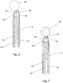
- Fig. 5 shows another embodiment of a surgical snare.
- a sharp edge or blade 154 is attached to or integrally formed with the surface of the end cap 130 (i.e. as part of the reaction surface mentioned above).
- the blade 154 may further assist in obtaining a clean cut.
- the blade 154 and/or end cap 130 are configured to ensure that they reside fully within the catheter 110.
- the distal edge of the blade 154 is located proximally to the distal end of the tip section 122 of the catheter 110.
- the end cap 130 may include gaps or channels in the side walls of the top piece 136 to permit the loop of wire 112 to pass out beyond the catheter 110.
- Fig. 6 shows another embodiment of a surgical snare.
- the operative part of the snare is formed by a looped length of wire 156.
- the ends of the length of wire 156 forming the loop are not attached.
- one end 158 is attached to an inside surface of the catheter 110, e.g. in the tip section 122 thereof. The point of attachment is set back from the distal end of the tip section to allow the loop to be full retracted.
- the other end 160 of the length of wire 156 is attached, e.g. welded, to the distal end of the inner push rod 128.
- the length of wire 156 may be formed from an alloy that exhibits shape memory properties (e.g. nitinol) so that it tends to adopt a looped configuration when extended out of the catheter 110.
- an end cap 162 terminates the distal end of the flexible actuator shaft 124.
- the end cap 162 may comprise an axial passageway through which the length of wire 156 (and inner push rod 128) travel during deployment of the snare.
- the end cap 162 may thus be formed as a single piece (e.g. of stainless steel).
- the end cap 162 may have a channel 164 or gap formed in its outer surface to permit the length of wire to travel past it from the attachment point inside the catheter 110.
- the length of wire may act like a cheese wire to pull biological tissue encircled by the loop against the top surface of the end cap 162.
- Fig. 7 shows another embodiment of a surgical snare.
- the operative part of the snare is formed by a double looped length of wire 166.
- the end cap includes a U-shaped passage 168 for receiving a portion of the double looped length of wire 166. This has the effect of utilising the force used to close the loop as means for supporting the reaction surface, which may give greater control over the cutting process.
- the end cap may include a movable tip portion 170 (which may be biased back into the end cap by a spring or the like) which can be brought out of the end cap into contact with tissue gather in the loop during closure of the loop.
- the movable tip portion 170 may have a sharpened distal edge or a blade mounted thereon.
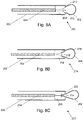
- Fig. 8A shows a schematic cross-sectional view through a distal end of a snare device 200 according to another embodiment.
- the snare device 200 comprises a flexible actuator shaft comprising an outer sleeve 202 (e.g. made form nylon) and an inner push rod 204 (e.g. made from stainless steel) that is mounted within and slidable relative to the outer sleeve 202.
- a nibless loop of wire 206 is connected to a distal end of the inner push rod.
- the loop of wire may be made of a plurality of braided nitinol strands or a single nitinol strand. In this example, both ends of the loop are connected to the push rod 204.
- one end is fixed to the end cap 208 (e.g. in the internal passageway) and the other end connected to the push rod 204.
- the loop of wire 206 in slidable by the action of the push rod 204 through an end cap 208 that is mounted at a distal end of the outer sleeve 202.
- the end cap may be made from stainless steel.
- the end cap 208 has an internal passageway (not shown) for receiving the nibless loop of wire.
- the end cap 208 has an indented distal surface 210 from which projects a thin blade 212.
- the blade 212 spans across the entrance to the internal passageway to provide a reaction surface against which the nibless loop of wire 206 bears when fully retracted into the end cap 208.
- the blade assists cutting of tissue captured in the loop.
- the indented distal surface ensures that the tip of the blade does not project substantially beyond the end of the outer sleeve 202.
- Fig. 8B shows a schematic cross-sectional view through a distal end of a snare device 214 according to another embodiment.
- the end cap 208 comprises a pair of internal passageways, one for each end of the loop 206.
- the end cap 208 has a concave distal face 216 that is sharpened in a cutting region 218 between the entrances to the internal passageways.
- the cutting region 218 forms a reaction surface against which the nibless loop of wire 206 bears when fully retracted into the end cap 208.
- the concave distal face 216 ensures that the cutting region does not project beyond the end of the outer sleeve 202.
- Fig. 8C shows a schematic cross-sectional view through a distal end of a snare device 220 according to another embodiment.
- the end cap 208 also comprises a pair of internal passageways (not shown), one for each end of the loop 206.
- the end cap 208 has a recessed mouth 222, and the distal end of the pair of passageway open into the base of the recessed mouth.
- the base of the recessed mouth 222 is sharpened in a cutting region 224 between the entrances to the internal passageways.
- the cutting region 224 forms a reaction surface against which the nibless loop of wire 206 bears when fully retracted into the end cap 208.
- the recessed mouth 222 ensures that the cutting region does not project beyond the end of the outer sleeve 202.
- the loop of wire extends distally from the tip section of the catheter.
- the passageway in the snare cap may open through a side surface of the tip section, so that the loop of wire is directed to one side of the device.
Landscapes
- Health & Medical Sciences (AREA)
- Life Sciences & Earth Sciences (AREA)
- Surgery (AREA)
- Molecular Biology (AREA)
- General Health & Medical Sciences (AREA)
- Biomedical Technology (AREA)
- Heart & Thoracic Surgery (AREA)
- Medical Informatics (AREA)
- Nuclear Medicine, Radiotherapy & Molecular Imaging (AREA)
- Animal Behavior & Ethology (AREA)
- Engineering & Computer Science (AREA)
- Public Health (AREA)
- Veterinary Medicine (AREA)
- Orthopedic Medicine & Surgery (AREA)
- Vascular Medicine (AREA)
- Surgical Instruments (AREA)
- Materials For Medical Uses (AREA)
- Saccharide Compounds (AREA)
Applications Claiming Priority (2)
| Application Number | Priority Date | Filing Date | Title |
|---|---|---|---|
| GBGB1418368.5A GB201418368D0 (en) | 2014-10-16 | 2014-10-16 | Surgical snare |
| PCT/EP2015/074004 WO2016059210A1 (en) | 2014-10-16 | 2015-10-16 | Surgical snare |
Publications (2)
| Publication Number | Publication Date |
|---|---|
| EP3206601A1 EP3206601A1 (en) | 2017-08-23 |
| EP3206601B1 true EP3206601B1 (en) | 2022-07-27 |
Family
ID=52013082
Family Applications (1)
| Application Number | Title | Priority Date | Filing Date |
|---|---|---|---|
| EP15784000.0A Active EP3206601B1 (en) | 2014-10-16 | 2015-10-16 | Surgical snare |
Country Status (13)
| Country | Link |
|---|---|
| US (1) | US10835270B2 (enExample) |
| EP (1) | EP3206601B1 (enExample) |
| JP (1) | JP6607933B2 (enExample) |
| KR (1) | KR20170068495A (enExample) |
| CN (1) | CN107072687B (enExample) |
| AU (1) | AU2015332595B2 (enExample) |
| BR (1) | BR112017007354B1 (enExample) |
| CA (1) | CA2964668C (enExample) |
| ES (1) | ES2926060T3 (enExample) |
| GB (2) | GB201418368D0 (enExample) |
| PT (1) | PT3206601T (enExample) |
| SG (1) | SG11201703052UA (enExample) |
| WO (1) | WO2016059210A1 (enExample) |
Families Citing this family (46)
| Publication number | Priority date | Publication date | Assignee | Title |
|---|---|---|---|---|
| US6814739B2 (en) | 2001-05-18 | 2004-11-09 | U.S. Endoscopy Group, Inc. | Retrieval device |
| US8591521B2 (en) | 2007-06-08 | 2013-11-26 | United States Endoscopy Group, Inc. | Retrieval device |
| US8070694B2 (en) | 2008-07-14 | 2011-12-06 | Medtronic Vascular, Inc. | Fiber based medical devices and aspiration catheters |
| US9572591B2 (en) | 2013-09-03 | 2017-02-21 | United States Endoscopy Group, Inc. | Endoscopic snare device |
| US9265512B2 (en) | 2013-12-23 | 2016-02-23 | Silk Road Medical, Inc. | Transcarotid neurovascular catheter |
| US9629747B2 (en) | 2014-09-17 | 2017-04-25 | Iantech, Inc. | Devices and methods for cutting lenticular tissue |
| CN112826657B (zh) | 2014-09-17 | 2023-10-17 | 卡尔蔡司白内障医疗技术公司 | 用于取出晶状体组织的装置和方法 |
| EP4674460A3 (en) | 2015-02-04 | 2026-03-25 | Route 92 Medical, Inc. | Rapid aspiration thrombectomy system |
| US11065019B1 (en) | 2015-02-04 | 2021-07-20 | Route 92 Medical, Inc. | Aspiration catheter systems and methods of use |
| US10426497B2 (en) | 2015-07-24 | 2019-10-01 | Route 92 Medical, Inc. | Anchoring delivery system and methods |
| US10716915B2 (en) * | 2015-11-23 | 2020-07-21 | Mivi Neuroscience, Inc. | Catheter systems for applying effective suction in remote vessels and thrombectomy procedures facilitated by catheter systems |
| US10624785B2 (en) | 2016-01-30 | 2020-04-21 | Carl Zeiss Meditec Cataract Technology Inc. | Devices and methods for ocular surgery |
| WO2017203582A1 (ja) * | 2016-05-23 | 2017-11-30 | オリンパス株式会社 | 内視鏡用デバイスおよび内視鏡システム |
| CN110114023B (zh) | 2016-10-26 | 2022-03-29 | 卡尔蔡司白内障医疗技术公司 | 用于在眼睛中切割晶状体的方法和装置 |
| WO2018129551A1 (en) * | 2017-01-09 | 2018-07-12 | United States Endoscopy Group, Inc. | Endoscopic snare device |
| AU2018208460B2 (en) | 2017-01-10 | 2023-03-16 | Route 92 Medical, Inc. | Aspiration catheter systems and methods of use |
| CN106725738A (zh) * | 2017-01-17 | 2017-05-31 | 李达周 | 软式内镜组织粉碎装置 |
| CN114916978B (zh) | 2017-01-20 | 2025-02-25 | 92号医疗公司 | 单操作者颅内医疗装置输送系统和使用方法 |
| CN106983539B (zh) * | 2017-05-08 | 2020-05-19 | 南微医学科技股份有限公司 | 一种医用可旋转圈套器 |
| AU2018266237B2 (en) * | 2017-05-12 | 2021-04-22 | Ellenial Surgical, LLC | Fecalith removal system |
| US10478535B2 (en) | 2017-05-24 | 2019-11-19 | Mivi Neuroscience, Inc. | Suction catheter systems for applying effective aspiration in remote vessels, especially cerebral arteries |
| US11234723B2 (en) | 2017-12-20 | 2022-02-01 | Mivi Neuroscience, Inc. | Suction catheter systems for applying effective aspiration in remote vessels, especially cerebral arteries |
| KR102058037B1 (ko) * | 2017-10-11 | 2020-01-22 | (주)비엠에이 | 의료용 스네어 |
| KR102035102B1 (ko) * | 2017-11-09 | 2019-10-22 | 석재일 | 내시경 시술 기구 |
| JP7208237B2 (ja) * | 2017-12-08 | 2023-01-18 | オーリス ヘルス インコーポレイテッド | 医療手技を行うシステム及び医療機器 |
| KR102726086B1 (ko) | 2017-12-14 | 2024-11-06 | 칼 짜이스 메디텍 캐터랙트 테크놀로지 인크. | 안과 수술용 디바이스 |
| CN112423824B (zh) | 2018-05-17 | 2023-02-21 | 92号医疗公司 | 抽吸导管系统和使用方法 |
| AU2019326548B2 (en) | 2018-08-24 | 2023-11-23 | Auris Health, Inc. | Manually and robotically controllable medical instruments |
| JP7536752B2 (ja) | 2018-09-28 | 2024-08-20 | オーリス ヘルス インコーポレイテッド | 内視鏡支援経皮的医療処置のためのシステム及び方法 |
| KR102852843B1 (ko) | 2018-09-28 | 2025-09-03 | 아우리스 헬스, 인코포레이티드 | 의료 기구를 도킹시키기 위한 시스템 및 방법 |
| WO2020081946A1 (en) * | 2018-10-19 | 2020-04-23 | New Wave Endo-Surgery Inc. | Method and apparatus for intra-abdominal assembly, disassembly and retrieval of laparoscopic instruments |
| CN113226202B (zh) | 2018-12-28 | 2024-12-03 | 奥瑞斯健康公司 | 用于机器人医疗系统的经皮护套和方法 |
| US11007079B1 (en) | 2019-12-02 | 2021-05-18 | Richard Mackool | Ophthalmic surgical instruments and snares thereof |
| JP7526500B2 (ja) * | 2019-06-24 | 2024-08-01 | マククール,リチャード | 眼科用手術器具およびそのスネア |
| KR20220050151A (ko) | 2019-08-15 | 2022-04-22 | 아우리스 헬스, 인코포레이티드 | 다수의 굽힘 섹션을 갖는 의료 장치 |
| EP4084720A4 (en) | 2019-12-31 | 2024-01-17 | Auris Health, Inc. | ALIGNMENT TECHNIQUES FOR PERCUTANEOUS ACCESS |
| CN114929148B (zh) | 2019-12-31 | 2024-05-10 | 奥瑞斯健康公司 | 用于经皮进入的对准界面 |
| KR20220123273A (ko) | 2019-12-31 | 2022-09-06 | 아우리스 헬스, 인코포레이티드 | 해부학적 특징부 식별 및 표적설정 |
| US11617865B2 (en) | 2020-01-24 | 2023-04-04 | Mivi Neuroscience, Inc. | Suction catheter systems with designs allowing rapid clearing of clots |
| US11737663B2 (en) | 2020-03-30 | 2023-08-29 | Auris Health, Inc. | Target anatomical feature localization |
| DE202020104255U1 (de) | 2020-07-23 | 2021-10-26 | Hms Medical Gmbh | Vorrichtung zum Entfernen von erhabenem Zellgewebe, insbesondere von Tumoren |
| US11980412B2 (en) | 2020-09-15 | 2024-05-14 | Boston Scientific Medical Device Limited | Elongated medical sheath |
| EP4225167A4 (en) | 2020-10-09 | 2024-10-09 | Route 92 Medical, Inc. | ASPIRATION CATHETER SYSTEMS AND METHODS OF USE |
| WO2022159956A1 (en) | 2021-01-21 | 2022-07-28 | University Hospitals Cleveland Medical Center | Endoscopic tissue resection device |
| US20230346405A1 (en) * | 2022-04-28 | 2023-11-02 | United States Government As Represented By The Department Of Veterans Affairs | Clot Disruptor And Systems And Methods Of Using Same |
| KR102791309B1 (ko) * | 2022-07-01 | 2025-04-08 | 한정모 | 복수의 와이어를 이용한 수정체 절개 장치 |
Citations (3)
| Publication number | Priority date | Publication date | Assignee | Title |
|---|---|---|---|---|
| JPH1014922A (ja) * | 1996-07-03 | 1998-01-20 | Osamu Yoshida | 臓器細切器および臓器細切装置 |
| US6007546A (en) * | 1998-10-26 | 1999-12-28 | Boston Scientific Ltd. | Injection snare |
| WO2013103934A1 (en) * | 2012-01-06 | 2013-07-11 | University Of Louisville Research Foundation, Inc. | Endoscopic snare device |
Family Cites Families (29)
| Publication number | Priority date | Publication date | Assignee | Title |
|---|---|---|---|---|
| JPS482474Y1 (enExample) | 1969-12-23 | 1973-01-22 | ||
| US4538611A (en) * | 1983-06-13 | 1985-09-03 | Kelman Charles D | Surgical instrument and method of cutting a lens of an eye |
| US4718419A (en) | 1985-08-05 | 1988-01-12 | Olympus Optical Co., Ltd. | Snare assembly for endoscope |
| US5318564A (en) | 1992-05-01 | 1994-06-07 | Hemostatic Surgery Corporation | Bipolar surgical snare and methods of use |
| JP3806516B2 (ja) | 1998-07-02 | 2006-08-09 | オリンパス株式会社 | 内視鏡システム |
| AU4311199A (en) * | 1998-05-29 | 1999-12-20 | Proton Energy Systems | Fluids management system for water electrolysis |
| AU2001233500B2 (en) * | 2000-02-17 | 2005-02-17 | Kanag Baska | Surgical snare |
| WO2001060265A1 (en) * | 2000-02-17 | 2001-08-23 | Kanag Baska | Surgical snare |
| US6602262B2 (en) * | 2000-06-02 | 2003-08-05 | Scimed Life Systems, Inc. | Medical device having linear to rotation control |
| US20040220604A1 (en) | 2003-04-30 | 2004-11-04 | Fogarty Thomas J. | Tissue separation apparatus and method |
| JP2005110860A (ja) * | 2003-10-06 | 2005-04-28 | Olympus Corp | 医療用結紮装置 |
| JP4638683B2 (ja) | 2004-03-25 | 2011-02-23 | テルモ株式会社 | 血管内異物除去吸引用カテーテル |
| US7658738B2 (en) * | 2004-05-14 | 2010-02-09 | Ethicon Endo-Surgery, Inc. | Medical devices for use with endoscope |
| CN2745521Y (zh) | 2004-12-06 | 2005-12-14 | 何菊 | 动脉粥样硬化斑块切割器 |
| NZ554828A (en) | 2004-12-06 | 2010-07-30 | Washington Biotech Corp | Medicine injection devices and methods |
| US20060173468A1 (en) | 2005-01-28 | 2006-08-03 | Marc Simmon | Obturator introducer with snare |
| JP4823533B2 (ja) * | 2005-02-04 | 2011-11-24 | オリンパス株式会社 | 医療用縫合結紮具及び医療用縫合結紮装置 |
| US8932208B2 (en) * | 2005-05-26 | 2015-01-13 | Maquet Cardiovascular Llc | Apparatus and methods for performing minimally-invasive surgical procedures |
| EP2079373B1 (en) * | 2006-09-21 | 2018-12-19 | Mayo Foundation For Medical Education And Research | Devices for ligating anatomical structures |
| US8298243B2 (en) * | 2007-07-30 | 2012-10-30 | Tyco Healthcare Group Lp | Combination wire electrode and tube electrode polypectomy device |
| EP2052688B1 (en) * | 2007-10-25 | 2012-06-06 | pfm medical ag | Snare mechanism for surgical retrieval |
| US20090182324A1 (en) | 2008-01-16 | 2009-07-16 | Mel Kurtulus | Laproscopic electronic surgical instruments |
| EP2676626B1 (en) * | 2008-01-31 | 2019-11-20 | Covidien LP | Polyp removal device |
| US8961543B2 (en) * | 2008-10-20 | 2015-02-24 | Mayo Foundation For Medical Education And Research | Tissue ligation devices and methods |
| CN201453327U (zh) * | 2009-06-25 | 2010-05-12 | 安瑞医疗器械(杭州)有限公司 | 一种圈套器 |
| CN102639068B (zh) * | 2009-10-30 | 2015-07-08 | 库克医学技术有限责任公司 | 利用环圈构件在组织上维持力的装置 |
| CN202010184U (zh) * | 2011-02-17 | 2011-10-19 | 上海菲捷实业有限公司 | 一次性手术用高频圈套器 |
| WO2014116877A2 (en) * | 2013-01-23 | 2014-07-31 | Endochoice, Inc. | Surgical snare device |
| US10945756B2 (en) * | 2013-03-01 | 2021-03-16 | Catch Medical, Llc | Device of inserting and controlling a snare |
-
2014
- 2014-10-16 GB GBGB1418368.5A patent/GB201418368D0/en not_active Ceased
-
2015
- 2015-10-16 KR KR1020177011687A patent/KR20170068495A/ko not_active Abandoned
- 2015-10-16 WO PCT/EP2015/074004 patent/WO2016059210A1/en not_active Ceased
- 2015-10-16 JP JP2017520455A patent/JP6607933B2/ja not_active Expired - Fee Related
- 2015-10-16 US US15/518,725 patent/US10835270B2/en active Active
- 2015-10-16 ES ES15784000T patent/ES2926060T3/es active Active
- 2015-10-16 CN CN201580056221.3A patent/CN107072687B/zh not_active Expired - Fee Related
- 2015-10-16 PT PT157840000T patent/PT3206601T/pt unknown
- 2015-10-16 EP EP15784000.0A patent/EP3206601B1/en active Active
- 2015-10-16 CA CA2964668A patent/CA2964668C/en active Active
- 2015-10-16 SG SG11201703052UA patent/SG11201703052UA/en unknown
- 2015-10-16 BR BR112017007354-4A patent/BR112017007354B1/pt not_active IP Right Cessation
- 2015-10-16 GB GB1518324.7A patent/GB2532596B/en not_active Expired - Fee Related
- 2015-10-16 AU AU2015332595A patent/AU2015332595B2/en not_active Ceased
Patent Citations (3)
| Publication number | Priority date | Publication date | Assignee | Title |
|---|---|---|---|---|
| JPH1014922A (ja) * | 1996-07-03 | 1998-01-20 | Osamu Yoshida | 臓器細切器および臓器細切装置 |
| US6007546A (en) * | 1998-10-26 | 1999-12-28 | Boston Scientific Ltd. | Injection snare |
| WO2013103934A1 (en) * | 2012-01-06 | 2013-07-11 | University Of Louisville Research Foundation, Inc. | Endoscopic snare device |
Also Published As
| Publication number | Publication date |
|---|---|
| GB2532596A (en) | 2016-05-25 |
| CN107072687A (zh) | 2017-08-18 |
| PT3206601T (pt) | 2022-08-31 |
| BR112017007354B1 (pt) | 2022-11-16 |
| JP2017531512A (ja) | 2017-10-26 |
| KR20170068495A (ko) | 2017-06-19 |
| ES2926060T3 (es) | 2022-10-21 |
| CA2964668C (en) | 2023-01-17 |
| AU2015332595B2 (en) | 2019-08-01 |
| GB2532596B (en) | 2017-05-10 |
| GB201518324D0 (en) | 2015-12-02 |
| AU2015332595A1 (en) | 2017-05-18 |
| WO2016059210A1 (en) | 2016-04-21 |
| US20170231647A1 (en) | 2017-08-17 |
| CA2964668A1 (en) | 2016-04-21 |
| GB201418368D0 (en) | 2014-12-03 |
| SG11201703052UA (en) | 2017-05-30 |
| EP3206601A1 (en) | 2017-08-23 |
| US10835270B2 (en) | 2020-11-17 |
| BR112017007354A2 (pt) | 2017-12-19 |
| JP6607933B2 (ja) | 2019-11-20 |
| CN107072687B (zh) | 2023-12-05 |
Similar Documents
| Publication | Publication Date | Title |
|---|---|---|
| EP3206601B1 (en) | Surgical snare | |
| AU2015201540B2 (en) | Devices, systems, and methods for obtaining a tissue sample using a biopsy tool | |
| EP4005517B1 (en) | Endoscopic treatment tool | |
| US20180000470A1 (en) | Endoscopic vessel harvesting system components | |
| EP1522269A1 (en) | High-frequency knife and endoscopic apparatus | |
| CA2739003C (en) | Barrel system for use with an endoscope | |
| US9549661B2 (en) | Medical device actuation systems and related methods of use | |
| US10765444B2 (en) | Medical instrument for ablation of tissue | |
| US20140336611A1 (en) | Catheter sheath and tip | |
| US20140222014A1 (en) | Surgical Snare Device | |
| HK1243296A1 (en) | Surgical snare | |
| EP2011440A1 (en) | Endoscopic vessel harvesting system components | |
| EP4480432A2 (en) | Systems for a dissection tool | |
| JP2010094337A (ja) | 内視鏡用止血鉗子 |
Legal Events
| Date | Code | Title | Description |
|---|---|---|---|
| STAA | Information on the status of an ep patent application or granted ep patent |
Free format text: STATUS: THE INTERNATIONAL PUBLICATION HAS BEEN MADE |
|
| PUAI | Public reference made under article 153(3) epc to a published international application that has entered the european phase |
Free format text: ORIGINAL CODE: 0009012 |
|
| STAA | Information on the status of an ep patent application or granted ep patent |
Free format text: STATUS: REQUEST FOR EXAMINATION WAS MADE |
|
| 17P | Request for examination filed |
Effective date: 20170515 |
|
| AK | Designated contracting states |
Kind code of ref document: A1 Designated state(s): AL AT BE BG CH CY CZ DE DK EE ES FI FR GB GR HR HU IE IS IT LI LT LU LV MC MK MT NL NO PL PT RO RS SE SI SK SM TR |
|
| AX | Request for extension of the european patent |
Extension state: BA ME |
|
| DAV | Request for validation of the european patent (deleted) | ||
| DAX | Request for extension of the european patent (deleted) | ||
| STAA | Information on the status of an ep patent application or granted ep patent |
Free format text: STATUS: EXAMINATION IS IN PROGRESS |
|
| 17Q | First examination report despatched |
Effective date: 20201118 |
|
| GRAP | Despatch of communication of intention to grant a patent |
Free format text: ORIGINAL CODE: EPIDOSNIGR1 |
|
| STAA | Information on the status of an ep patent application or granted ep patent |
Free format text: STATUS: GRANT OF PATENT IS INTENDED |
|
| INTG | Intention to grant announced |
Effective date: 20220228 |
|
| GRAS | Grant fee paid |
Free format text: ORIGINAL CODE: EPIDOSNIGR3 |
|
| GRAA | (expected) grant |
Free format text: ORIGINAL CODE: 0009210 |
|
| STAA | Information on the status of an ep patent application or granted ep patent |
Free format text: STATUS: THE PATENT HAS BEEN GRANTED |
|
| AK | Designated contracting states |
Kind code of ref document: B1 Designated state(s): AL AT BE BG CH CY CZ DE DK EE ES FI FR GB GR HR HU IE IS IT LI LT LU LV MC MK MT NL NO PL PT RO RS SE SI SK SM TR |
|
| REG | Reference to a national code |
Ref country code: CH Ref legal event code: EP |
|
| REG | Reference to a national code |
Ref country code: DE Ref legal event code: R096 Ref document number: 602015080055 Country of ref document: DE |
|
| REG | Reference to a national code |
Ref country code: AT Ref legal event code: REF Ref document number: 1506547 Country of ref document: AT Kind code of ref document: T Effective date: 20220815 |
|
| REG | Reference to a national code |
Ref country code: IE Ref legal event code: FG4D Ref country code: PT Ref legal event code: SC4A Ref document number: 3206601 Country of ref document: PT Date of ref document: 20220831 Kind code of ref document: T Free format text: AVAILABILITY OF NATIONAL TRANSLATION Effective date: 20220825 |
|
| REG | Reference to a national code |
Ref country code: NL Ref legal event code: FP |
|
| REG | Reference to a national code |
Ref country code: ES Ref legal event code: FG2A Ref document number: 2926060 Country of ref document: ES Kind code of ref document: T3 Effective date: 20221021 |
|
| PGFP | Annual fee paid to national office [announced via postgrant information from national office to epo] |
Ref country code: PT Payment date: 20220920 Year of fee payment: 8 |
|
| REG | Reference to a national code |
Ref country code: LT Ref legal event code: MG9D |
|
| PGFP | Annual fee paid to national office [announced via postgrant information from national office to epo] |
Ref country code: NL Payment date: 20221024 Year of fee payment: 8 |
|
| PG25 | Lapsed in a contracting state [announced via postgrant information from national office to epo] |
Ref country code: SE Free format text: LAPSE BECAUSE OF FAILURE TO SUBMIT A TRANSLATION OF THE DESCRIPTION OR TO PAY THE FEE WITHIN THE PRESCRIBED TIME-LIMIT Effective date: 20220727 Ref country code: RS Free format text: LAPSE BECAUSE OF FAILURE TO SUBMIT A TRANSLATION OF THE DESCRIPTION OR TO PAY THE FEE WITHIN THE PRESCRIBED TIME-LIMIT Effective date: 20220727 Ref country code: NO Free format text: LAPSE BECAUSE OF FAILURE TO SUBMIT A TRANSLATION OF THE DESCRIPTION OR TO PAY THE FEE WITHIN THE PRESCRIBED TIME-LIMIT Effective date: 20221027 Ref country code: LV Free format text: LAPSE BECAUSE OF FAILURE TO SUBMIT A TRANSLATION OF THE DESCRIPTION OR TO PAY THE FEE WITHIN THE PRESCRIBED TIME-LIMIT Effective date: 20220727 Ref country code: LT Free format text: LAPSE BECAUSE OF FAILURE TO SUBMIT A TRANSLATION OF THE DESCRIPTION OR TO PAY THE FEE WITHIN THE PRESCRIBED TIME-LIMIT Effective date: 20220727 Ref country code: FI Free format text: LAPSE BECAUSE OF FAILURE TO SUBMIT A TRANSLATION OF THE DESCRIPTION OR TO PAY THE FEE WITHIN THE PRESCRIBED TIME-LIMIT Effective date: 20220727 |
|
| PGFP | Annual fee paid to national office [announced via postgrant information from national office to epo] |
Ref country code: AT Payment date: 20220927 Year of fee payment: 8 |
|
| PG25 | Lapsed in a contracting state [announced via postgrant information from national office to epo] |
Ref country code: PL Free format text: LAPSE BECAUSE OF FAILURE TO SUBMIT A TRANSLATION OF THE DESCRIPTION OR TO PAY THE FEE WITHIN THE PRESCRIBED TIME-LIMIT Effective date: 20220727 Ref country code: IS Free format text: LAPSE BECAUSE OF FAILURE TO SUBMIT A TRANSLATION OF THE DESCRIPTION OR TO PAY THE FEE WITHIN THE PRESCRIBED TIME-LIMIT Effective date: 20221127 Ref country code: HR Free format text: LAPSE BECAUSE OF FAILURE TO SUBMIT A TRANSLATION OF THE DESCRIPTION OR TO PAY THE FEE WITHIN THE PRESCRIBED TIME-LIMIT Effective date: 20220727 Ref country code: GR Free format text: LAPSE BECAUSE OF FAILURE TO SUBMIT A TRANSLATION OF THE DESCRIPTION OR TO PAY THE FEE WITHIN THE PRESCRIBED TIME-LIMIT Effective date: 20221028 |
|
| PGFP | Annual fee paid to national office [announced via postgrant information from national office to epo] |
Ref country code: CH Payment date: 20221026 Year of fee payment: 8 |
|
| PG25 | Lapsed in a contracting state [announced via postgrant information from national office to epo] |
Ref country code: SM Free format text: LAPSE BECAUSE OF FAILURE TO SUBMIT A TRANSLATION OF THE DESCRIPTION OR TO PAY THE FEE WITHIN THE PRESCRIBED TIME-LIMIT Effective date: 20220727 Ref country code: RO Free format text: LAPSE BECAUSE OF FAILURE TO SUBMIT A TRANSLATION OF THE DESCRIPTION OR TO PAY THE FEE WITHIN THE PRESCRIBED TIME-LIMIT Effective date: 20220727 Ref country code: DK Free format text: LAPSE BECAUSE OF FAILURE TO SUBMIT A TRANSLATION OF THE DESCRIPTION OR TO PAY THE FEE WITHIN THE PRESCRIBED TIME-LIMIT Effective date: 20220727 Ref country code: CZ Free format text: LAPSE BECAUSE OF FAILURE TO SUBMIT A TRANSLATION OF THE DESCRIPTION OR TO PAY THE FEE WITHIN THE PRESCRIBED TIME-LIMIT Effective date: 20220727 |
|
| REG | Reference to a national code |
Ref country code: DE Ref legal event code: R097 Ref document number: 602015080055 Country of ref document: DE |
|
| PG25 | Lapsed in a contracting state [announced via postgrant information from national office to epo] |
Ref country code: SK Free format text: LAPSE BECAUSE OF FAILURE TO SUBMIT A TRANSLATION OF THE DESCRIPTION OR TO PAY THE FEE WITHIN THE PRESCRIBED TIME-LIMIT Effective date: 20220727 Ref country code: MC Free format text: LAPSE BECAUSE OF FAILURE TO SUBMIT A TRANSLATION OF THE DESCRIPTION OR TO PAY THE FEE WITHIN THE PRESCRIBED TIME-LIMIT Effective date: 20220727 Ref country code: EE Free format text: LAPSE BECAUSE OF FAILURE TO SUBMIT A TRANSLATION OF THE DESCRIPTION OR TO PAY THE FEE WITHIN THE PRESCRIBED TIME-LIMIT Effective date: 20220727 |
|
| PLBE | No opposition filed within time limit |
Free format text: ORIGINAL CODE: 0009261 |
|
| STAA | Information on the status of an ep patent application or granted ep patent |
Free format text: STATUS: NO OPPOSITION FILED WITHIN TIME LIMIT |
|
| REG | Reference to a national code |
Ref country code: BE Ref legal event code: MM Effective date: 20221031 |
|
| PG25 | Lapsed in a contracting state [announced via postgrant information from national office to epo] |
Ref country code: LU Free format text: LAPSE BECAUSE OF NON-PAYMENT OF DUE FEES Effective date: 20221016 Ref country code: AL Free format text: LAPSE BECAUSE OF FAILURE TO SUBMIT A TRANSLATION OF THE DESCRIPTION OR TO PAY THE FEE WITHIN THE PRESCRIBED TIME-LIMIT Effective date: 20220727 |
|
| 26N | No opposition filed |
Effective date: 20230502 |
|
| REG | Reference to a national code |
Ref country code: AT Ref legal event code: UEP Ref document number: 1506547 Country of ref document: AT Kind code of ref document: T Effective date: 20220727 |
|
| PG25 | Lapsed in a contracting state [announced via postgrant information from national office to epo] |
Ref country code: SI Free format text: LAPSE BECAUSE OF FAILURE TO SUBMIT A TRANSLATION OF THE DESCRIPTION OR TO PAY THE FEE WITHIN THE PRESCRIBED TIME-LIMIT Effective date: 20220727 |
|
| PG25 | Lapsed in a contracting state [announced via postgrant information from national office to epo] |
Ref country code: BE Free format text: LAPSE BECAUSE OF NON-PAYMENT OF DUE FEES Effective date: 20221031 |
|
| PGFP | Annual fee paid to national office [announced via postgrant information from national office to epo] |
Ref country code: GB Payment date: 20231023 Year of fee payment: 9 |
|
| PGFP | Annual fee paid to national office [announced via postgrant information from national office to epo] |
Ref country code: ES Payment date: 20231101 Year of fee payment: 9 |
|
| PGFP | Annual fee paid to national office [announced via postgrant information from national office to epo] |
Ref country code: IT Payment date: 20231024 Year of fee payment: 9 Ref country code: IE Payment date: 20231023 Year of fee payment: 9 Ref country code: FR Payment date: 20231027 Year of fee payment: 9 Ref country code: DE Payment date: 20231027 Year of fee payment: 9 |
|
| PG25 | Lapsed in a contracting state [announced via postgrant information from national office to epo] |
Ref country code: HU Free format text: LAPSE BECAUSE OF FAILURE TO SUBMIT A TRANSLATION OF THE DESCRIPTION OR TO PAY THE FEE WITHIN THE PRESCRIBED TIME-LIMIT; INVALID AB INITIO Effective date: 20151016 |
|
| PG25 | Lapsed in a contracting state [announced via postgrant information from national office to epo] |
Ref country code: CY Free format text: LAPSE BECAUSE OF FAILURE TO SUBMIT A TRANSLATION OF THE DESCRIPTION OR TO PAY THE FEE WITHIN THE PRESCRIBED TIME-LIMIT Effective date: 20220727 |
|
| PG25 | Lapsed in a contracting state [announced via postgrant information from national office to epo] |
Ref country code: MK Free format text: LAPSE BECAUSE OF FAILURE TO SUBMIT A TRANSLATION OF THE DESCRIPTION OR TO PAY THE FEE WITHIN THE PRESCRIBED TIME-LIMIT Effective date: 20220727 |
|
| REG | Reference to a national code |
Ref country code: CH Ref legal event code: PL |
|
| REG | Reference to a national code |
Ref country code: NL Ref legal event code: MM Effective date: 20231101 |
|
| REG | Reference to a national code |
Ref country code: AT Ref legal event code: MM01 Ref document number: 1506547 Country of ref document: AT Kind code of ref document: T Effective date: 20231016 |
|
| PG25 | Lapsed in a contracting state [announced via postgrant information from national office to epo] |
Ref country code: TR Free format text: LAPSE BECAUSE OF FAILURE TO SUBMIT A TRANSLATION OF THE DESCRIPTION OR TO PAY THE FEE WITHIN THE PRESCRIBED TIME-LIMIT Effective date: 20220727 |
|
| PG25 | Lapsed in a contracting state [announced via postgrant information from national office to epo] |
Ref country code: CH Free format text: LAPSE BECAUSE OF NON-PAYMENT OF DUE FEES Effective date: 20231031 Ref country code: NL Free format text: LAPSE BECAUSE OF NON-PAYMENT OF DUE FEES Effective date: 20231101 |
|
| PG25 | Lapsed in a contracting state [announced via postgrant information from national office to epo] |
Ref country code: AT Free format text: LAPSE BECAUSE OF NON-PAYMENT OF DUE FEES Effective date: 20231016 |
|
| PG25 | Lapsed in a contracting state [announced via postgrant information from national office to epo] |
Ref country code: NL Free format text: LAPSE BECAUSE OF NON-PAYMENT OF DUE FEES Effective date: 20231101 Ref country code: CH Free format text: LAPSE BECAUSE OF NON-PAYMENT OF DUE FEES Effective date: 20231031 Ref country code: BG Free format text: LAPSE BECAUSE OF FAILURE TO SUBMIT A TRANSLATION OF THE DESCRIPTION OR TO PAY THE FEE WITHIN THE PRESCRIBED TIME-LIMIT Effective date: 20220727 Ref country code: AT Free format text: LAPSE BECAUSE OF NON-PAYMENT OF DUE FEES Effective date: 20231016 |
|
| PG25 | Lapsed in a contracting state [announced via postgrant information from national office to epo] |
Ref country code: PT Free format text: LAPSE BECAUSE OF NON-PAYMENT OF DUE FEES Effective date: 20240416 |
|
| PG25 | Lapsed in a contracting state [announced via postgrant information from national office to epo] |
Ref country code: PT Free format text: LAPSE BECAUSE OF NON-PAYMENT OF DUE FEES Effective date: 20240416 |
|
| PG25 | Lapsed in a contracting state [announced via postgrant information from national office to epo] |
Ref country code: MT Free format text: LAPSE BECAUSE OF FAILURE TO SUBMIT A TRANSLATION OF THE DESCRIPTION OR TO PAY THE FEE WITHIN THE PRESCRIBED TIME-LIMIT Effective date: 20220727 |
|
| REG | Reference to a national code |
Ref country code: DE Ref legal event code: R119 Ref document number: 602015080055 Country of ref document: DE |
|
| GBPC | Gb: european patent ceased through non-payment of renewal fee |
Effective date: 20241016 |
|
| PG25 | Lapsed in a contracting state [announced via postgrant information from national office to epo] |
Ref country code: DE Free format text: LAPSE BECAUSE OF NON-PAYMENT OF DUE FEES Effective date: 20250501 |
|
| PG25 | Lapsed in a contracting state [announced via postgrant information from national office to epo] |
Ref country code: GB Free format text: LAPSE BECAUSE OF NON-PAYMENT OF DUE FEES Effective date: 20241016 |
|
| PG25 | Lapsed in a contracting state [announced via postgrant information from national office to epo] |
Ref country code: FR Free format text: LAPSE BECAUSE OF NON-PAYMENT OF DUE FEES Effective date: 20241031 |
|
| PG25 | Lapsed in a contracting state [announced via postgrant information from national office to epo] |
Ref country code: IT Free format text: LAPSE BECAUSE OF NON-PAYMENT OF DUE FEES Effective date: 20241016 |
|
| PG25 | Lapsed in a contracting state [announced via postgrant information from national office to epo] |
Ref country code: IE Free format text: LAPSE BECAUSE OF NON-PAYMENT OF DUE FEES Effective date: 20241016 |
|
| REG | Reference to a national code |
Ref country code: ES Ref legal event code: FD2A Effective date: 20251203 |
|
| PG25 | Lapsed in a contracting state [announced via postgrant information from national office to epo] |
Ref country code: ES Free format text: LAPSE BECAUSE OF NON-PAYMENT OF DUE FEES Effective date: 20241017 |