EP3205366A1 - Hüllen für polymergerüst - Google Patents
Hüllen für polymergerüst Download PDFInfo
- Publication number
- EP3205366A1 EP3205366A1 EP17159927.7A EP17159927A EP3205366A1 EP 3205366 A1 EP3205366 A1 EP 3205366A1 EP 17159927 A EP17159927 A EP 17159927A EP 3205366 A1 EP3205366 A1 EP 3205366A1
- Authority
- EP
- European Patent Office
- Prior art keywords
- sheath
- scaffold
- length
- protecting
- catheter
- Prior art date
- Legal status (The legal status is an assumption and is not a legal conclusion. Google has not performed a legal analysis and makes no representation as to the accuracy of the status listed.)
- Withdrawn
Links
- 229920000642 polymer Polymers 0.000 title abstract description 33
- 238000002788 crimping Methods 0.000 abstract description 28
- 230000036541 health Effects 0.000 abstract description 17
- 238000000034 method Methods 0.000 description 38
- 239000002184 metal Substances 0.000 description 17
- 239000000463 material Substances 0.000 description 16
- 229910052751 metal Inorganic materials 0.000 description 16
- 230000036316 preload Effects 0.000 description 14
- 230000008569 process Effects 0.000 description 11
- 230000000452 restraining effect Effects 0.000 description 8
- 230000002452 interceptive effect Effects 0.000 description 6
- 210000004204 blood vessel Anatomy 0.000 description 4
- 230000007246 mechanism Effects 0.000 description 4
- 229920001432 poly(L-lactide) Polymers 0.000 description 4
- 230000009467 reduction Effects 0.000 description 4
- 230000002829 reductive effect Effects 0.000 description 4
- JVTAAEKCZFNVCJ-REOHCLBHSA-N L-lactic acid Chemical compound C[C@H](O)C(O)=O JVTAAEKCZFNVCJ-REOHCLBHSA-N 0.000 description 3
- 229910001092 metal group alloy Inorganic materials 0.000 description 3
- 239000002861 polymer material Substances 0.000 description 3
- 208000031481 Pathologic Constriction Diseases 0.000 description 2
- 238000002399 angioplasty Methods 0.000 description 2
- 239000011248 coating agent Substances 0.000 description 2
- 238000000576 coating method Methods 0.000 description 2
- 230000006870 function Effects 0.000 description 2
- 239000007769 metal material Substances 0.000 description 2
- 230000004048 modification Effects 0.000 description 2
- 238000012986 modification Methods 0.000 description 2
- 238000004806 packaging method and process Methods 0.000 description 2
- 229920001434 poly(D-lactide) Polymers 0.000 description 2
- -1 poly(L-lactide) Polymers 0.000 description 2
- 229920001606 poly(lactic acid-co-glycolic acid) Polymers 0.000 description 2
- 238000004513 sizing Methods 0.000 description 2
- 230000036262 stenosis Effects 0.000 description 2
- 208000037804 stenosis Diseases 0.000 description 2
- RBMHUYBJIYNRLY-UHFFFAOYSA-N 2-[(1-carboxy-1-hydroxyethyl)-hydroxyphosphoryl]-2-hydroxypropanoic acid Chemical compound OC(=O)C(O)(C)P(O)(=O)C(C)(O)C(O)=O RBMHUYBJIYNRLY-UHFFFAOYSA-N 0.000 description 1
- 241001082241 Lythrum hyssopifolia Species 0.000 description 1
- 239000004677 Nylon Substances 0.000 description 1
- 229920002614 Polyether block amide Polymers 0.000 description 1
- 208000007536 Thrombosis Diseases 0.000 description 1
- 230000002411 adverse Effects 0.000 description 1
- 229910045601 alloy Inorganic materials 0.000 description 1
- 239000000956 alloy Substances 0.000 description 1
- 210000001367 artery Anatomy 0.000 description 1
- 238000005452 bending Methods 0.000 description 1
- 229920013641 bioerodible polymer Polymers 0.000 description 1
- 150000001875 compounds Chemical class 0.000 description 1
- 238000010276 construction Methods 0.000 description 1
- 238000007887 coronary angioplasty Methods 0.000 description 1
- 238000005336 cracking Methods 0.000 description 1
- 239000003814 drug Substances 0.000 description 1
- 229940079593 drug Drugs 0.000 description 1
- 238000012377 drug delivery Methods 0.000 description 1
- 230000002708 enhancing effect Effects 0.000 description 1
- 230000035876 healing Effects 0.000 description 1
- 238000010348 incorporation Methods 0.000 description 1
- 238000013152 interventional procedure Methods 0.000 description 1
- 230000002427 irreversible effect Effects 0.000 description 1
- 150000002739 metals Chemical class 0.000 description 1
- 229920001778 nylon Polymers 0.000 description 1
- 229920003023 plastic Polymers 0.000 description 1
- 239000004033 plastic Substances 0.000 description 1
- 239000004417 polycarbonate Substances 0.000 description 1
- 229920000515 polycarbonate Polymers 0.000 description 1
- 239000004810 polytetrafluoroethylene Substances 0.000 description 1
- 229920001343 polytetrafluoroethylene Polymers 0.000 description 1
- 230000005855 radiation Effects 0.000 description 1
- 230000008439 repair process Effects 0.000 description 1
- 239000000126 substance Substances 0.000 description 1
- 230000002792 vascular Effects 0.000 description 1
Images


Classifications
-
- A—HUMAN NECESSITIES
- A61—MEDICAL OR VETERINARY SCIENCE; HYGIENE
- A61M—DEVICES FOR INTRODUCING MEDIA INTO, OR ONTO, THE BODY; DEVICES FOR TRANSDUCING BODY MEDIA OR FOR TAKING MEDIA FROM THE BODY; DEVICES FOR PRODUCING OR ENDING SLEEP OR STUPOR
- A61M25/00—Catheters; Hollow probes
- A61M25/10—Balloon catheters
-
- A—HUMAN NECESSITIES
- A61—MEDICAL OR VETERINARY SCIENCE; HYGIENE
- A61F—FILTERS IMPLANTABLE INTO BLOOD VESSELS; PROSTHESES; DEVICES PROVIDING PATENCY TO, OR PREVENTING COLLAPSING OF, TUBULAR STRUCTURES OF THE BODY, e.g. STENTS; ORTHOPAEDIC, NURSING OR CONTRACEPTIVE DEVICES; FOMENTATION; TREATMENT OR PROTECTION OF EYES OR EARS; BANDAGES, DRESSINGS OR ABSORBENT PADS; FIRST-AID KITS
- A61F2/00—Filters implantable into blood vessels; Prostheses, i.e. artificial substitutes or replacements for parts of the body; Appliances for connecting them with the body; Devices providing patency to, or preventing collapsing of, tubular structures of the body, e.g. stents
- A61F2/0095—Packages or dispensers for prostheses or other implants
-
- A—HUMAN NECESSITIES
- A61—MEDICAL OR VETERINARY SCIENCE; HYGIENE
- A61F—FILTERS IMPLANTABLE INTO BLOOD VESSELS; PROSTHESES; DEVICES PROVIDING PATENCY TO, OR PREVENTING COLLAPSING OF, TUBULAR STRUCTURES OF THE BODY, e.g. STENTS; ORTHOPAEDIC, NURSING OR CONTRACEPTIVE DEVICES; FOMENTATION; TREATMENT OR PROTECTION OF EYES OR EARS; BANDAGES, DRESSINGS OR ABSORBENT PADS; FIRST-AID KITS
- A61F2/00—Filters implantable into blood vessels; Prostheses, i.e. artificial substitutes or replacements for parts of the body; Appliances for connecting them with the body; Devices providing patency to, or preventing collapsing of, tubular structures of the body, e.g. stents
- A61F2/95—Instruments specially adapted for placement or removal of stents or stent-grafts
- A61F2/9522—Means for mounting a stent or stent-graft onto or into a placement instrument
- A61F2/9524—Iris-type crimpers
-
- A—HUMAN NECESSITIES
- A61—MEDICAL OR VETERINARY SCIENCE; HYGIENE
- A61F—FILTERS IMPLANTABLE INTO BLOOD VESSELS; PROSTHESES; DEVICES PROVIDING PATENCY TO, OR PREVENTING COLLAPSING OF, TUBULAR STRUCTURES OF THE BODY, e.g. STENTS; ORTHOPAEDIC, NURSING OR CONTRACEPTIVE DEVICES; FOMENTATION; TREATMENT OR PROTECTION OF EYES OR EARS; BANDAGES, DRESSINGS OR ABSORBENT PADS; FIRST-AID KITS
- A61F2/00—Filters implantable into blood vessels; Prostheses, i.e. artificial substitutes or replacements for parts of the body; Appliances for connecting them with the body; Devices providing patency to, or preventing collapsing of, tubular structures of the body, e.g. stents
- A61F2/95—Instruments specially adapted for placement or removal of stents or stent-grafts
- A61F2/958—Inflatable balloons for placing stents or stent-grafts
-
- A—HUMAN NECESSITIES
- A61—MEDICAL OR VETERINARY SCIENCE; HYGIENE
- A61F—FILTERS IMPLANTABLE INTO BLOOD VESSELS; PROSTHESES; DEVICES PROVIDING PATENCY TO, OR PREVENTING COLLAPSING OF, TUBULAR STRUCTURES OF THE BODY, e.g. STENTS; ORTHOPAEDIC, NURSING OR CONTRACEPTIVE DEVICES; FOMENTATION; TREATMENT OR PROTECTION OF EYES OR EARS; BANDAGES, DRESSINGS OR ABSORBENT PADS; FIRST-AID KITS
- A61F2/00—Filters implantable into blood vessels; Prostheses, i.e. artificial substitutes or replacements for parts of the body; Appliances for connecting them with the body; Devices providing patency to, or preventing collapsing of, tubular structures of the body, e.g. stents
- A61F2/95—Instruments specially adapted for placement or removal of stents or stent-grafts
- A61F2/962—Instruments specially adapted for placement or removal of stents or stent-grafts having an outer sleeve
-
- A—HUMAN NECESSITIES
- A61—MEDICAL OR VETERINARY SCIENCE; HYGIENE
- A61M—DEVICES FOR INTRODUCING MEDIA INTO, OR ONTO, THE BODY; DEVICES FOR TRANSDUCING BODY MEDIA OR FOR TAKING MEDIA FROM THE BODY; DEVICES FOR PRODUCING OR ENDING SLEEP OR STUPOR
- A61M25/00—Catheters; Hollow probes
- A61M25/10—Balloon catheters
- A61M25/1027—Making of balloon catheters
- A61M25/1036—Making parts for balloon catheter systems, e.g. shafts or distal ends
-
- A—HUMAN NECESSITIES
- A61—MEDICAL OR VETERINARY SCIENCE; HYGIENE
- A61F—FILTERS IMPLANTABLE INTO BLOOD VESSELS; PROSTHESES; DEVICES PROVIDING PATENCY TO, OR PREVENTING COLLAPSING OF, TUBULAR STRUCTURES OF THE BODY, e.g. STENTS; ORTHOPAEDIC, NURSING OR CONTRACEPTIVE DEVICES; FOMENTATION; TREATMENT OR PROTECTION OF EYES OR EARS; BANDAGES, DRESSINGS OR ABSORBENT PADS; FIRST-AID KITS
- A61F2/00—Filters implantable into blood vessels; Prostheses, i.e. artificial substitutes or replacements for parts of the body; Appliances for connecting them with the body; Devices providing patency to, or preventing collapsing of, tubular structures of the body, e.g. stents
- A61F2/95—Instruments specially adapted for placement or removal of stents or stent-grafts
- A61F2/958—Inflatable balloons for placing stents or stent-grafts
- A61F2002/9583—Means for holding the stent on the balloon, e.g. using protrusions, adhesives or an outer sleeve
-
- A—HUMAN NECESSITIES
- A61—MEDICAL OR VETERINARY SCIENCE; HYGIENE
- A61M—DEVICES FOR INTRODUCING MEDIA INTO, OR ONTO, THE BODY; DEVICES FOR TRANSDUCING BODY MEDIA OR FOR TAKING MEDIA FROM THE BODY; DEVICES FOR PRODUCING OR ENDING SLEEP OR STUPOR
- A61M25/00—Catheters; Hollow probes
- A61M25/10—Balloon catheters
- A61M2025/1043—Balloon catheters with special features or adapted for special applications
- A61M2025/1081—Balloon catheters with special features or adapted for special applications having sheaths or the like for covering the balloon but not forming a permanent part of the balloon, e.g. retractable, dissolvable or tearable sheaths
-
- Y—GENERAL TAGGING OF NEW TECHNOLOGICAL DEVELOPMENTS; GENERAL TAGGING OF CROSS-SECTIONAL TECHNOLOGIES SPANNING OVER SEVERAL SECTIONS OF THE IPC; TECHNICAL SUBJECTS COVERED BY FORMER USPC CROSS-REFERENCE ART COLLECTIONS [XRACs] AND DIGESTS
- Y10—TECHNICAL SUBJECTS COVERED BY FORMER USPC
- Y10T—TECHNICAL SUBJECTS COVERED BY FORMER US CLASSIFICATION
- Y10T29/00—Metal working
- Y10T29/49—Method of mechanical manufacture
- Y10T29/49826—Assembling or joining
- Y10T29/49863—Assembling or joining with prestressing of part
- Y10T29/49865—Assembling or joining with prestressing of part by temperature differential [e.g., shrink fit]
-
- Y—GENERAL TAGGING OF NEW TECHNOLOGICAL DEVELOPMENTS; GENERAL TAGGING OF CROSS-SECTIONAL TECHNOLOGIES SPANNING OVER SEVERAL SECTIONS OF THE IPC; TECHNICAL SUBJECTS COVERED BY FORMER USPC CROSS-REFERENCE ART COLLECTIONS [XRACs] AND DIGESTS
- Y10—TECHNICAL SUBJECTS COVERED BY FORMER USPC
- Y10T—TECHNICAL SUBJECTS COVERED BY FORMER US CLASSIFICATION
- Y10T29/00—Metal working
- Y10T29/49—Method of mechanical manufacture
- Y10T29/49826—Assembling or joining
- Y10T29/49908—Joining by deforming
- Y10T29/49909—Securing cup or tube between axially extending concentric annuli
- Y10T29/49913—Securing cup or tube between axially extending concentric annuli by constricting outer annulus
Definitions
- a variety of non-surgical interventional procedures have been developed over the years for opening stenosed or occluded blood vessels in a patient caused by the build up of plaque or other substances on the walls of the blood vessel. Such procedures usually involve the percutaneous introduction of an interventional device into the lumen of the artery.
- the stenosis can be treated by placing an expandable interventional device such as an expandable stent into the stenosed region to hold open and sometimes expand the segment of blood vessel or other arterial lumen.
- Metal or metal alloy stents have been found useful in the treatment or repair of blood vessels after a stenosis has been compressed by percutaneous transluminal coronary angioplasty (PTCA), percutaneous transluminal angioplasty (PTA) or removal by other means.
- Metal stents are typically delivered in a compressed condition to the target site, then deployed at the target into an expanded condition or deployed state to support the vessel.
- Metal stents have traditionally fallen into two general categories - balloon expanded and self-expanding.
- the later type expands to a deployed or expanded state within a vessel when a radial restraint is removed, while the former relies on an externally-applied force to configure it from a crimped or stowed state to the deployed or expanded state.
- Balloon expanded stents are expanded upon application of an external force through inflation of a balloon, upon which the stent is crimped.
- the expanding balloon applies a radial outward force on the luminal surfaces of the stent.
- the stent undergoes a plastic or irreversible deformation in the sense that the stent will essentially maintain its deformed, deployed state after balloon pressure is withdrawn.
- Balloon expanded stents may also be disposed within a sheath, either during a transluminal delivery to a target site or during the assembly of the stent-balloon catheter delivery system.
- the balloon expanded stent may be contained within a sheath when delivered to a target site to minimize dislodgment of the stent from the balloon while en route to the target vessel.
- Sheaths may also be used to protect a drug eluting stent during a crimping process, which presses or crimps the stent to the balloon catheter.
- the blades of the crimper When an iris-type crimping mechanism, for example, is used to crimp a stent to balloon, the blades of the crimper, often hardened metal, can form gouges in a drug-polymer coating or even strip off coating such as when the blades and/or stent struts are misaligned during the diameter reduction.
- stents that utilize a sheath to protect the stent during a crimping process are found in US 6783542 and US 6805703 .
- a stent in a body may be necessary for a limited period of time until its intended function of, for example, maintaining vascular patency and/or drug delivery is accomplished.
- biodegradable scaffolds as opposed to a metal stent, allow for improved healing of the anatomical lumen and reduced incidence of late stent thrombosis.
- a polymer scaffold in particular a bioerodible polymer scaffold, as opposed to a metal stent, so that the prosthesis's presence in the vessel is for a limited duration.
- a delivery system having a polymer scaffold there are numerous challenges to overcome when developing a delivery system having a polymer scaffold.
- Polymer material considered for use as a polymeric scaffold e.g. poly(L-lactide) ("PLLA”), poly(L-lactide-co-glycolide) (“PLGA”), poly(D-lactide-co-glycolide) or poly(L-lactide-co-D-lactide) (“PLLA-co-PDLA”) with less than 10% D-lactide, and PLLD/PDLA stereo complex, may be described, through comparison with a metallic material used to form a stent, in some of the following ways.
- a suitable polymer has a low strength to weight ratio, which means more material is needed to provide an equivalent mechanical property to that of a metal.
- struts must be made thicker and wider to have the required strength for a stent to support lumen walls at a desired radius.
- the scaffold made from such polymers also tends to be brittle or have limited fracture toughness.
- the anisotropic and rate-dependant inelastic properties i.e., strength / stiffness of the material varies depending upon the rate at which the material is deformed) inherent in the material only compound this complexity in working with a polymer, particularly, bio-absorbable polymer such as PLLA or PLGA. Challenges faced when securing a polymer scaffold to a delivery balloon are discussed in U.S. Patent Application Serial No. 12/861,719 (Attorney docket 62571.448).
- a metal stent may be crimped to a balloon in such a manner as to minimize, if not eliminate recoil in the metal structure after removal from the crimp head.
- Metal materials used for stents are generally capable of being worked more during the crimping process than polymer materials. This desirable property of the metal allows for less concern over the metal stent - balloon engagement changing over time when the stent-catheter is packaged and awaiting use in a medical procedure.
- Sheaths arranged according to the invention provide an effective radial constraint for preventing recoil in a crimped scaffold, yet are comparatively easy to manually remove from the scaffold.
- a sheath that applies a radial constraint can be difficult to remove manually without damaging the crimped scaffold, dislodging or shifting it on the balloon.
- a sheath pair is used to impose a higher radial inward constraint on a crimped polymer scaffold than is possible using a single sheath that must be manually removed from the scaffold before the scaffold can be introduced into a patient.
- a sheath pair covering a crimped scaffold is removed by sliding a first sheath over a second sheath until the first sheath abuts an end of the second sheath, at which point the second sheath is removed by simultaneously pulling on both sheaths.
- a method for assembling a scaffold-balloon catheter comprising providing a balloon-catheter having a scaffold crimped to the balloon; and constraining the crimped scaffold including placing a protecting sheath over the scaffold to protect the scaffold, then pushing a constraining sheath over the protecting sheath to constrain recoil in the scaffold using the constraining sheath; wherein the scaffold is configured for being passed through the body of a patient only after the constraining sheath and protecting sheath are removed.
- an apparatus comprising a catheter assembly having a distal end and including a scaffold comprising a polymer crimped to a balloon; a sheath disposed over the scaffold, the sheath applying a radial inward force on the crimped scaffold to limit recoil of the scaffold; the sheath extending distally of the catheter distal end by about a length equal to the length of the scaffold; and wherein the apparatus is configured for being passed through the body of a patient only after the sheath is removed.
- the sheath may comprise a protecting sheath and a constraining sheath that is placed over the protecting sheath and the crimped scaffold to limit recoil of the scaffold by an applying an inwardly directed radial force on the crimped scaffold.
- an apparatus comprising a scaffold crimped to a balloon of a catheter, the catheter having a distal end and the scaffold being crimped to the balloon proximally of the distal end; a first sheath disposed over the scaffold, the first sheath including an extension that is distal of the catheter distal end; and a second sheath disposed over the scaffold; wherein the first sheath and second sheath are configured such that the apparatus is capable of being configured into a medical device suitable for being introduced into a patient by (a) pulling the second sheath distally along the first sheath outer surface such that the second sheath is displaced to a location substantially distal of the scaffold or the catheter distal end, and (b) after the first sheath has been moved to the substantially distal location, removing the first sheath from the scaffold by pulling the second sheath against the first sheath extension, thereby displacing the first sheath distally with the second sheath.
- an apparatus comprising a scaffold crimped to a balloon of a catheter, the catheter having a distal end and the scaffold being crimped to the balloon proximally of the distal end; a first sheath disposed over the scaffold, the first sheath including an extension distal of the catheter distal end and a portion forming an interfering ledge disposed proximal to the scaffold; and a second sheath disposed over the scaffold and first sheath, the second sheath applying a preload to the scaffold and the first sheath to maintain contact between the first sheath and scaffold; wherein the first sheath is removable from the scaffold only after the second sheath has been moved to the distal extension such that the interfering ledge is capable of deflecting away from the scaffold only when the second sheath is removed from the scaffold; and wherein the apparatus is configured as a medical device suitable for being introduced into a patient when the first and second sheaths are removed from the catheter.
- the ratio of the starting diameter (before crimping) to the final crimp diameter may be 2:1, 2.5:1, 3:1, or higher.
- the ratio of starting diameter to final crimped diameter may be greater than the ratio of the deployed diameter to the final crimped diameter of the scaffold, e.g., from about 4:1 to 6:1.
- Examples of polymers that may be used to construct sheaths described herein are Pebax, PTFE, Polyethelene, Polycarbonate, Polymide and Nylon.
- Examples of restraining sheaths for polymer scaffold, and methods for attaching and removing restraining sheaths for polymer scaffold are described in U.S. application no. 12/916,349 (docket no. 104584.7).
- FIG. 1 shows a side view of a distal portion of a scaffold-balloon catheter assembly 2.
- the catheter assembly 2 includes a catheter shaft 4 and a scaffold 10 crimped to a delivery balloon 12. As shown there are two separate sheaths 20, 30 disposed over the scaffold 10.
- the scaffold 10 is contained within a protecting sheath 20 and a constraining sheath 30, which is slid over the outer surface of the protecting sheath 20 to position it over the scaffold 10.
- both the constraining sheath 30 and protecting sheath 20 are removed by a health professional.
- the sheaths 20, 30 provide an effective radial constraint for reducing recoil in the crimped scaffold 10. Yet the sheaths 20, 30 are also easily removed by a health professional at the time of a medical procedure. A sheath that applies a radial constraint can be difficult to manually remove without adversely affecting the structural integrity of the medical device. In these cases, it is desirable to arrange the sheaths so that special handling is not required by the health professional when the sheath is manually removed. By making the sheath removal process easy to follow or intuitive, the possibility that a health professional will damage the medical device by improperly removing the sheath is reduced.
- the constraint imposed by the sheaths 20, 30 maintain the scaffold 10 at essentially the same, or close to the same diameter it had when removed from the crimping mechanism, i.e., the crimped crossing profile, which is needed for traversing tortuous vessels to deliver the scaffold 10 to a target location in a body.
- the sheath 30 is tightly fit over the sheath 20 and scaffold 10 so that the radial inward force applied on the scaffold 10 can reduce recoil in the scaffold 10.
- the health professional may then remove both sheaths at the time of the medical procedure. As such, any potential recoil in the scaffold 10 prior to using the medical device is minimized.
- the constraining sheath 30 is located over the section of the protecting sheath 20 where the crimped scaffold 10 is found.
- This sheath 30 is made from a polymer tube material having a thickness and pre-stressed inner diameter size suitably chosen to cause the sheath 30 to apply a radially inward directed force on the scaffold 10. The thicker the tube and the smaller the pre-stressed inner diameter size for the sheath 30 the higher this constraint will be on the scaffold 10. However, the sheath 30 thickness should not be too thick, nor its inner diameter too small as this will make it difficult to slide the sheath 30 over, or remove the sheath 30 from the scaffold 10. If excessive force is needed to reposition the sheath 30, the scaffold 10 can dislodge from the balloon 12 or become damaged when the sheath 30 is moved.
- the sheath 20 serves to protect the integrity of the scaffold-balloon structure as the sheath 30 is repositioned relative to the scaffold 10.
- the protecting sheath 20 extends over the entire length of the scaffold (as shown) and beyond the distal tip 6 of the catheter, for reasons that will become apparent.
- the protecting sheath 20 is preferably formed from a unitary piece of polymer material, which is shaped to form differently sized portions 22, 24 and 25 for protecting the scaffold/balloon 10/12.
- a raised end 22 in the form of a cylinder section having a larger diameter than the body portion 21 of the sheath 20 to the right of end 22 which covers the scaffold 10 in FIG. 1 .
- raised end 22 provides an abutting surface with respect to distal movement of sheath 30, i.e., end 30b of sheath 30 abuts end 22 when sheath 30 is moved to the left in FIG. 1 .
- End 22 may alternatively take the shape of a cone with the largest diameter end of the cone being the most distal end of the sheath 20.
- the raised end 22 is used to remove the sheaths 20, 30, as explained below.
- the protecting sheath 20 has a cut 26, extending from the proximal end 20a to a location about at the distal the tip 6 of the catheter assembly 2.
- the cut 26 forms an upper and lower separable halve 28, 29 of the sheath 20. These halves 29, 28 are configured to freely move apart when the sheath 30 is positioned towards the distal end 20b.
- the location 26a may be thought of as a living hinge 26a about which the upper half 29 and lower half 28 of the sheath 20 can rotate, or deflect away from the scaffold 10.
- halves 28, 29 will tend to open up naturally, due to the preload applied by sheath 30 near hinge 26a (the separable halves 28, 29 can be more clearly seen in FIGS. 2A-2D ).
- This arrangement for halves 29, 28 allows sheath 20 it to be easily removed from the scaffold 10 with minimal disruption to scaffold-balloon structural integrity, after sheath 30 is moved to distal end 20b.
- the presence of the halves 28, 29 prevent direct contact between the sliding sheath 30 and the surface of the scaffold 10.
- portions 24 and 25 formed when the combined proximal ends of halves 28, 29 are brought together as in FIG. 1 .
- the portions 24 and 25 take the form of a stepped or notched portion 25 and a raised end 24 similar to end 22, as shown in FIG. 1 and the cross-sectional view of the proximal end 20a of the assembly of FIG. 1A .
- the notched or stepped portion 25 has an outer diameter less than the outer diameter of the portion 21 of the sheath that covers the scaffold 10, as well as the outer diameter of the scaffold/balloon 10/12.
- the raised end 24 has a diameter that is greater than the body portion 21.
- FIG. 1A shows the distal end 20a with the sheath 30 (shown in phantom) replaced by the inwardly directed preload F30 it applies to sheath portion 21 when positioned over the scaffold 10.
- a distal end of portion 25 forms a ledge 25a.
- the inwardly directed preload F30 applied to sheath portion 21 urges the halves 29, 28 together.
- the scaffold/balloon proximal end 14a blocks movement of the sheath 20 to the left in FIG. 1A by interfering with the movement of the ledge 25a to the left.
- the first sheath 30 is moved to the distal end 20b of the sheath 20 (thereby removing the preload F30) so that the halves 28, 29 freely open up to allow the ledge 25a to easily pass over the scaffold 10 so that sheath 20 is removed without resistance.
- the user is thereby informed that the sheath 20 is removed properly when there is no resistance to removing the sheath 20 from the balloon-catheter assembly 2.
- This length beyond the distal end 6 facilitates an intuitive sliding removal or attachment of the sheath 30 from / to the scaffold 10 by respectively sliding the sheath 30 along the sheath 20 extension that is distal of tip 6 of the catheter assembly 2.
- the length of the sheath 20 that extends beyond the distal end 4 of the catheter assembly 2 may depend on the choice of sheaths used.
- a thicker or higher modulus sheath 20 and/or sheath 30 may be desirable to increase the resistance to improper removal of sheath 20, e.g., as when a user attempts to remove sheath 20 with, or before removing sheath 30 from the scaffold 10 (as discussed earlier).
- FIG. 2A shows the sheath 20 with the sheath 30.
- sheath 30 is sized to have a length L30 such that sheath 30 applies a sufficiently uniform radial inward force or preload on the scaffold 10 when end 30a abuts end 24a.
- the length L30 should therefore be slightly greater than the length of the scaffold-balloon structure.
- the sheath 30 can be slid towards or away from the scaffold location (i.e., its location in FIG. 2A or FIG. 1 ) over the sheath outer surface 20.
- FIG. 2D is a perspective view of the upper and lower halves 28, 29 separated from each other. As can be appreciated from this view, the halves 28, 29 rotate about the hinge 26a when they separate.
- FIGS. 2B and 2C show an additional side and perspective view, respectively, of the sheath 20 showing the aforementioned structure, including the portions of notched or stepped portion 25 and end 24 discussed earlier.
- the length L20 in FIG. 2C should be chosen to extend over the scaffold 10 length as well as a sufficient distance beyond the scaffold 10 so that the sheath 30 can be pushed onto the scaffold 10, and removed from the scaffold 10 while the halves 28, 29 are disposed over the scaffold 10.
- sheath 30 thickness and/or inner diameter size is selected with the sheath 20 in mind. That is, the sizing of one can determine what sizing to use for the other, based on achieving an appropriate balance among the amount of pre-load F30 ( FIG.
- the ease in which the sheath 30 can be placed over or removed from the scaffold 10 location increasing resistance to improper removal of sheath 20 (ledge 25a abutting proximal end 14a, as discussed above) and avoiding disruption to the integrity of the scaffold-balloon structure, e.g., pulling the scaffold 10 off the balloon when the sheath 30 is being removed.
- the sheath 30 will impose a higher localized pre-load on the scaffold 10.
- the scaffold 10 is more likely to be affected by sheath 30 movement because the sheath 20 easily deforms under the movement of the sheath 30.
- the scaffold 10 will not be as affected by movement of the sheath 30. And local changes in pre-load on the scaffold 10 will tend to be lower since the sheath 20 does not deform as easily under the movement of the sheath 30.
- the scaffold 10 is crimped to the balloon 12 of the catheter assembly 2 using a crimping mechanism.
- the diameter reduction during crimping may be 2:1, 2.5:1, 3:1, 4:1 or higher. This diameter reduction introduces high stresses in the scaffold structure.
- the memory in the material following crimping causes recoil of the scaffold structure, as discussed earlier.
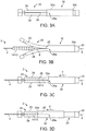
- the sheath pair shown in FIG. 3A , is placed on a mandrel 8 before being attached to the catheter assembly 2.
- the mandrel 8 is passed through the catheter shaft 4 guidewire lumen (not shown), and exits at the distal end 6 of the catheter assembly 2.
- the sheath pair is then placed on the mandrel 8 distally of the catheter assembly 2.
- the mandrel 8 is then used to guide the sheath pair over the scaffold-balloon 10/12 as illustrated in FIGS. 3B-3D .
- the distal end 30a of the sheath 30 is adjacent to the raised end 22 of the sheath 20.
- the halves 28, 29 can freely open or close.
- the sheath pair is then brought towards the scaffold-balloon 10/12.
- the halves 28, 29 easily deflect over the scaffold-balloon 10/12.
- the sheath pair may be slid towards the scaffold-balloon 10/12 as follows. Holding the catheter assembly 2 stationary, grasping the mandrel 8 with one hand and the sheath pair with the other hand and sliding the sheath pair over the mandrel 8 until the halves 28, 29 are located over the scaffold-balloon 10/12 as shown in FIG. 3C .
- the portions 24, 25 are positioned with respect to proximal end 14a as shown in FIG. 1A .
- the constraining sheath 30 can be pushed over the scaffold-balloon 10/12 (as indicated in FIGS. 3C-3D by P).
- the sheath 30 may be pushed over the scaffold-balloon 10/12 in the following manner.
- the raised end 22 and mandrel 8 are grasped with one hand to hold the two stationary.
- the sheath 30 is pushed over the scaffold-balloon 10/12 until the end 30a of sheath 30 is disposed adjacent to, or abuts the raised end 24 of the sheath 20, which indicates the proximate location of the proximal end 14a of the balloon-scaffold 10/12.
- the portion 24 and catheter shaft 4 may be simultaneously held with on hand, while the sheath 30 is pushed towards the scaffold 10 with the other hand.
- the halves 28, 29 are held in place relative to the scaffold 10 while the sheath 30 is being pushed over the scaffold 10.
- FIG. 4A depicts the arrangement of the sheaths 20, 30 at the distal end of the catheter assembly 2 when the packaged and sterile medical device is received by a health professional. Examples of such sterile packaging is found in U.S. patent publication no. US 2008-0010947 (docket no. 62571.60).
- the sheath 20 extends well-beyond the distal end 6 of the catheter 2 assembly such that it overhangs the distal end 6.
- FIGS. 4B-4C methods for removing the sheath pair from the scaffold-balloon 10/12 by the health professional are now described. These illustrations refer to moving the sheath pair over the mandrel 8; however, a mandrel 8 is not necessary. The sheath pair may be safely removed from the catheter assembly 2 without using a mandrel 8.
- the sheath 30 is pulled away from the scaffold-balloon 10/12 structure, where it is shown positioned in FIG. 4A .
- the sheath 30 may be withdrawn or pulled away from the scaffold-balloon 10/12 in the following manner.
- One hand grasps the raised end 22 and mandrel 8, to hold the two stationary, while the other hand grasps and pulls the sheath 30 towards the raised end 22.
- the sheath 30 reaches the raised end 22 the halves 28, 29 should freely deflect away from the scaffold 10 surface, since a majority if not all of the cut 26 is to the left of the sheath 30 ( FIG. 4B ).
- both sheaths 20, 30 can be simultaneously pulled away from the scaffold-balloon 10/12.
- the raised end 22 therefore functions as an abutment for removing both sheaths in a safe manner with minimal disruption to the crimped scaffold.
- This final pulling away of the sheath 20 from scaffold 10 may also simultaneously remove the stiffening mandrel 8 from the catheter shaft 4 lumen.
- the proximal abutment 224 is shown in a frontal view in FIG. 5B .
- the abutment 224 may take the form of a cross having ends 225a, 225b, 225c and 225d.
- the ends 225 form raised abutment surfaces that prevent or resist the sheath 30 from being moved to the left of the sheath 200 when the two are positioned over the scaffold.
- the sheath 30 may slip proximally of the scaffold 10, thereby removing the constraint on the scaffold.
- the same type of abutment 222 may also be formed at the distal end.
- the raised ends 222, 224 may be formed after the sheaths 20, 30 have been positioned over the scaffold-balloon 10/12 structure using, e.g., a hand crimper.
- the hand crimper is applied at the location 224 to form the cross members 225 ( FIG. 5B ) and also at the distal end of sheath 200 a similar structure 222.
Landscapes
- Health & Medical Sciences (AREA)
- Engineering & Computer Science (AREA)
- Biomedical Technology (AREA)
- Heart & Thoracic Surgery (AREA)
- Life Sciences & Earth Sciences (AREA)
- Animal Behavior & Ethology (AREA)
- Veterinary Medicine (AREA)
- Public Health (AREA)
- General Health & Medical Sciences (AREA)
- Transplantation (AREA)
- Vascular Medicine (AREA)
- Oral & Maxillofacial Surgery (AREA)
- Cardiology (AREA)
- Child & Adolescent Psychology (AREA)
- Biophysics (AREA)
- Pulmonology (AREA)
- Anesthesiology (AREA)
- Hematology (AREA)
- Materials For Medical Uses (AREA)
- Media Introduction/Drainage Providing Device (AREA)
Applications Claiming Priority (2)
| Application Number | Priority Date | Filing Date | Title |
|---|---|---|---|
| US13/118,311 US8414528B2 (en) | 2011-05-27 | 2011-05-27 | Polymer scaffold sheaths |
| EP12725274.0A EP2714171B1 (de) | 2011-05-27 | 2012-05-25 | Hüllen für polymergerüst |
Related Parent Applications (1)
| Application Number | Title | Priority Date | Filing Date |
|---|---|---|---|
| EP12725274.0A Division EP2714171B1 (de) | 2011-05-27 | 2012-05-25 | Hüllen für polymergerüst |
Publications (1)
| Publication Number | Publication Date |
|---|---|
| EP3205366A1 true EP3205366A1 (de) | 2017-08-16 |
Family
ID=46201883
Family Applications (2)
| Application Number | Title | Priority Date | Filing Date |
|---|---|---|---|
| EP17159927.7A Withdrawn EP3205366A1 (de) | 2011-05-27 | 2012-05-25 | Hüllen für polymergerüst |
| EP12725274.0A Not-in-force EP2714171B1 (de) | 2011-05-27 | 2012-05-25 | Hüllen für polymergerüst |
Family Applications After (1)
| Application Number | Title | Priority Date | Filing Date |
|---|---|---|---|
| EP12725274.0A Not-in-force EP2714171B1 (de) | 2011-05-27 | 2012-05-25 | Hüllen für polymergerüst |
Country Status (5)
| Country | Link |
|---|---|
| US (3) | US8414528B2 (de) |
| EP (2) | EP3205366A1 (de) |
| JP (1) | JP5979738B2 (de) |
| CN (2) | CN103826687B (de) |
| WO (1) | WO2012166661A1 (de) |
Families Citing this family (40)
| Publication number | Priority date | Publication date | Assignee | Title |
|---|---|---|---|---|
| CN102014806B (zh) * | 2008-05-09 | 2013-10-30 | 安吉奥米德医药技术有限责任两合公司 | 将扩张件置入套管中的方法 |
| GB0815339D0 (en) * | 2008-08-21 | 2008-10-01 | Angiomed Ag | Method of loading a stent into a sheath |
| US8414528B2 (en) | 2011-05-27 | 2013-04-09 | Abbott Cardiovascular Systems Inc. | Polymer scaffold sheaths |
| US8852257B2 (en) | 2011-06-21 | 2014-10-07 | Abbott Cardiovascular Systems Inc. | Sheaths used with polymer scaffold |
| US9956097B2 (en) | 2012-10-23 | 2018-05-01 | Abbott Cardiovascular Systems Inc. | Methods for vascular restoration therapy |
| US9072590B2 (en) | 2012-12-07 | 2015-07-07 | Abbott Cardiovascular Systems Inc. | Sheaths reducing recoil and loss of retention for polymer scaffolds crimped to balloons |
| US9078740B2 (en) | 2013-01-21 | 2015-07-14 | Howmedica Osteonics Corp. | Instrumentation and method for positioning and securing a graft |
| US9662231B2 (en) | 2013-03-15 | 2017-05-30 | Abbott Cardiovascular Systems Inc. | Polymer scaffolds having enhanced axial fatigue properties |
| CN105307716B (zh) * | 2013-05-03 | 2021-09-14 | C·R·巴德公司 | 可剥离保护套 |
| US10039656B2 (en) | 2013-06-05 | 2018-08-07 | Abbott Cardiovascular Systems Inc. | Coupled scaffold segments |
| US9675483B2 (en) | 2013-06-21 | 2017-06-13 | Abbott Cardiovascular Systems Inc. | Protective sheath assembly for a polymer scaffold |
| US9788983B2 (en) * | 2013-06-21 | 2017-10-17 | Abbott Cardiovascular Systems Inc. | Removable sheath assembly for a polymer scaffold |
| US10245145B2 (en) * | 2013-09-16 | 2019-04-02 | Symetis Sa | Method and apparatus for compressing/loading stent-valves |
| US10098771B2 (en) | 2013-09-25 | 2018-10-16 | Abbott Cardiovascular Systems Inc. | Clip sheath for a polymer scaffold |
| US9913958B2 (en) | 2014-02-28 | 2018-03-13 | Abbott Cardiovascular Systems Inc. | Protective sheaths for medical devices |
| US9364361B2 (en) * | 2014-03-13 | 2016-06-14 | Abbott Cardiovascular Systems Inc. | Striped sheaths for medical devices |
| WO2016044788A2 (en) | 2014-09-18 | 2016-03-24 | Abbott Cardiovascular Systems Inc. | Thermal processing of polymer scaffolds |
| US10569063B2 (en) | 2014-10-03 | 2020-02-25 | W. L. Gore & Associates, Inc. | Removable covers for drug eluting medical devices |
| US10080675B2 (en) | 2015-08-24 | 2018-09-25 | Abbott Cardiovascular Systems Inc. | System and method for conditioning an endoprosthesis |
| WO2017055919A1 (en) | 2015-09-28 | 2017-04-06 | M-V Arterica AB | Vascular closure device |
| WO2017215427A1 (zh) * | 2016-06-12 | 2017-12-21 | 上海微创医疗器械(集团)有限公司 | 束缚装置、支架系统以及束缚装置的使用方法 |
| CN107488345B (zh) * | 2016-06-12 | 2020-08-25 | 上海微创医疗器械(集团)有限公司 | 装置、支架束缚装置以及支架束缚方法 |
| CN108113783B (zh) * | 2016-11-28 | 2019-11-26 | 上海微创医疗器械(集团)有限公司 | 支架的保护装置及其制造方法、医疗装置 |
| CN110381897A (zh) * | 2016-12-29 | 2019-10-25 | 波士顿科学国际有限公司 | 用于将支架装载至递送装置中的方法 |
| JP6949546B2 (ja) * | 2017-04-28 | 2021-10-13 | 川澄化学工業株式会社 | 搬送用カテーテル及び血管内留置具搬送装置 |
| JP7103721B2 (ja) * | 2017-06-05 | 2022-07-20 | Sbカワスミ株式会社 | 搬送用カテーテル及び血管内留置具搬送装置 |
| WO2019098921A1 (en) | 2017-11-16 | 2019-05-23 | M-V Arterica AB | Vascular closure device, a hemostasis device comprising collapsible tubes adjacent anchors, and methods for using the devices. |
| US20190142403A1 (en) | 2017-11-16 | 2019-05-16 | M-V Arterica AB | Tissue closure device |
| US10668255B2 (en) | 2018-01-19 | 2020-06-02 | Medtronic Vascular, Inc. | Sheath for medically expandable balloon |
| US10737071B2 (en) * | 2018-01-19 | 2020-08-11 | Medtronic, Inc. | Splittable sheath |
| US10682492B2 (en) | 2018-01-19 | 2020-06-16 | Medtronic Vascular, Inc. | Expandable balloon sheath |
| US10688287B2 (en) | 2018-01-19 | 2020-06-23 | Medtronic, Inc. | Sheath including sheath body and sheath insert |
| US10702673B2 (en) * | 2018-01-19 | 2020-07-07 | Medtronic Vascular, Inc. | Expandable balloon sheaths |
| CN110123497A (zh) * | 2018-02-02 | 2019-08-16 | 上海微创医疗器械(集团)有限公司 | 支架的保护装置及医疗装置 |
| US11389627B1 (en) | 2018-10-02 | 2022-07-19 | Lutonix Inc. | Balloon protectors, balloon-catheter assemblies, and methods thereof |
| US12108945B2 (en) * | 2018-10-24 | 2024-10-08 | Arterica Inc. | Self-expanding hemostatic devices and methods for fascia and vessel passages |
| JP7712683B2 (ja) | 2019-11-19 | 2025-07-24 | アーテリカ, インコーポレイテッド | 血管閉鎖デバイスおよび方法 |
| CN111529154A (zh) * | 2020-04-30 | 2020-08-14 | 北京阿迈特医疗器械有限公司 | 具有回弹性或自膨胀性能的医疗器械的保护结构 |
| TW202237215A (zh) * | 2020-12-31 | 2022-10-01 | 美商阿比奥梅德公司 | 用於可壓縮導管泵的壓接工具 |
| US20240082537A1 (en) * | 2022-09-08 | 2024-03-14 | Orlando Health, Inc. | Catheter cover for urinary catheter |
Citations (11)
| Publication number | Priority date | Publication date | Assignee | Title |
|---|---|---|---|---|
| WO1998039056A2 (en) * | 1997-03-05 | 1998-09-11 | Scimed Life Systems, Inc. | Catheter with removable balloon protector and stent delivery system with removable stent protector |
| US6254609B1 (en) | 1999-01-11 | 2001-07-03 | Scimed Life Systems, Inc. | Self-expanding stent delivery system with two sheaths |
| US20020052640A1 (en) | 2000-08-04 | 2002-05-02 | Steve Bigus | Sheath for self-expanding stents |
| WO2002060345A2 (en) * | 2001-01-22 | 2002-08-08 | Gore Enterprise Holdings, Inc. | Deployment system for intraluminal devices |
| US20030004561A1 (en) | 2001-06-28 | 2003-01-02 | Steve Bigus | Peeling sheath for self-expanding stent |
| US20040093005A1 (en) * | 2002-09-30 | 2004-05-13 | Durcan Jonathan P. | Protective sleeve assembly for a balloon catheter |
| US6783542B2 (en) | 2001-02-22 | 2004-08-31 | Scimed Life Systems, Inc | Crimpable balloon/stent protector |
| US6805703B2 (en) | 2001-09-18 | 2004-10-19 | Scimed Life Systems, Inc. | Protective membrane for reconfiguring a workpiece |
| US20080010947A1 (en) | 2006-07-13 | 2008-01-17 | Bin Huang | Reduced temperature sterilization of stents |
| US20100004735A1 (en) | 2008-05-02 | 2010-01-07 | Arlene Sucy Yang | Polymeric Stent |
| WO2011094048A1 (en) * | 2010-01-27 | 2011-08-04 | Abbott Laboratories | Dual sheath assembly and method of use |
Family Cites Families (82)
| Publication number | Priority date | Publication date | Assignee | Title |
|---|---|---|---|---|
| US4243050A (en) | 1977-12-13 | 1981-01-06 | Littleford Philip O | Method for inserting pacemaker electrodes and the like |
| US4581025A (en) | 1983-11-14 | 1986-04-08 | Cook Incorporated | Sheath |
| US4710181A (en) | 1985-06-11 | 1987-12-01 | Genus Catheter Technologies, Inc. | Variable diameter catheter |
| US4846811A (en) | 1987-01-29 | 1989-07-11 | International Medical Innovators, Inc. | Sliding sheath for medical needles |
| US5015231A (en) | 1989-04-21 | 1991-05-14 | Scimed Life Systems, Inc. | Multipart split sleeve balloon protector for dilatation catheter |
| DE4018525C2 (de) | 1990-06-09 | 1994-05-05 | Kaltenbach Martin | Katheter mit einem aufweitbaren Bereich |
| CA2060067A1 (en) | 1991-01-28 | 1992-07-29 | Lilip Lau | Stent delivery system |
| US5158545A (en) | 1991-05-02 | 1992-10-27 | Brigham And Women's Hospital | Diameter expansion cannula |
| US5386817A (en) | 1991-06-10 | 1995-02-07 | Endomedical Technologies, Inc. | Endoscope sheath and valve system |
| US5935122A (en) | 1991-12-13 | 1999-08-10 | Endovascular Technologies, Inc. | Dual valve, flexible expandable sheath and method |
| US5395349A (en) | 1991-12-13 | 1995-03-07 | Endovascular Technologies, Inc. | Dual valve reinforced sheath and method |
| US5643175A (en) | 1992-09-01 | 1997-07-01 | Adair; Edwin L. | Sterilizable endoscope with separable disposable tube assembly |
| US5352236A (en) | 1992-09-29 | 1994-10-04 | Medtronic, Inc. | Balloon protector |
| US5250033A (en) | 1992-10-28 | 1993-10-05 | Interventional Thermodynamics, Inc. | Peel-away introducer sheath having proximal fitting |
| US5458615A (en) | 1993-07-06 | 1995-10-17 | Advanced Cardiovascular Systems, Inc. | Stent delivery system |
| KR970004845Y1 (ko) | 1993-09-27 | 1997-05-21 | 주식회사 수호메디테크 | 내강확장용 의료용구 |
| DE69533952T2 (de) | 1994-02-07 | 2006-01-12 | Kabushiki Kaisha Igaki Iryo Sekkei | Stentvorrichtung und stentversorgungssystem |
| DE69528216T2 (de) | 1994-06-17 | 2003-04-17 | Terumo K.K., Tokio/Tokyo | Verfahren zur Herstellung eines Dauerstents |
| US5569294A (en) | 1994-09-26 | 1996-10-29 | Medtronic, Inc. | Two piece balloon protector |
| US5765682A (en) | 1994-10-13 | 1998-06-16 | Menlo Care, Inc. | Restrictive package for expandable or shape memory medical devices and method of preventing premature change of same |
| US5591226A (en) | 1995-01-23 | 1997-01-07 | Schneider (Usa) Inc. | Percutaneous stent-graft and method for delivery thereof |
| US5647857A (en) | 1995-03-16 | 1997-07-15 | Endotex Interventional Systems, Inc. | Protective intraluminal sheath |
| US5788707A (en) | 1995-06-07 | 1998-08-04 | Scimed Life Systems, Inc. | Pull back sleeve system with compression resistant inner shaft |
| US5776141A (en) | 1995-08-28 | 1998-07-07 | Localmed, Inc. | Method and apparatus for intraluminal prosthesis delivery |
| GB9518400D0 (en) | 1995-09-08 | 1995-11-08 | Anson Medical Ltd | A surgical graft/stent system |
| DK0775470T3 (da) | 1995-11-14 | 1999-10-18 | Schneider Europ Gmbh | Stenindsætningsapparat |
| US5693066A (en) | 1995-12-21 | 1997-12-02 | Medtronic, Inc. | Stent mounting and transfer device and method |
| US5749852A (en) | 1996-07-23 | 1998-05-12 | Medtronic, Inc. | Sheath system for autoperfusion dilatation catheter balloon |
| US5868707A (en) | 1996-08-15 | 1999-02-09 | Advanced Cardiovascular Systems, Inc. | Protective sheath for catheter balloons |
| US5800517A (en) | 1996-08-19 | 1998-09-01 | Scimed Life Systems, Inc. | Stent delivery system with storage sleeve |
| US6254628B1 (en) | 1996-12-09 | 2001-07-03 | Micro Therapeutics, Inc. | Intracranial stent |
| DE69726317T2 (de) * | 1996-09-18 | 2004-09-16 | Micro Therapeutics, Inc., Irvine | Intrakranialer stent |
| US6010529A (en) | 1996-12-03 | 2000-01-04 | Atrium Medical Corporation | Expandable shielded vessel support |
| US5893868A (en) | 1997-03-05 | 1999-04-13 | Scimed Life Systems, Inc. | Catheter with removable balloon protector and stent delivery system with removable stent protector |
| US5992000A (en) | 1997-10-16 | 1999-11-30 | Scimed Life Systems, Inc. | Stent crimper |
| IE980241A1 (en) * | 1998-04-02 | 1999-10-20 | Salviac Ltd | Delivery catheter with split sheath |
| US6110146A (en) | 1998-09-30 | 2000-08-29 | Medtronic Ave, Inc. | Protector for catheter balloon with guidewire backloading system |
| US6544278B1 (en) | 1998-11-06 | 2003-04-08 | Scimed Life Systems, Inc. | Rolling membrane stent delivery system |
| NL1012527C2 (nl) | 1999-07-06 | 2001-01-09 | Cordis Europ | Ballonkatheter met scheurlijn. |
| US6533806B1 (en) | 1999-10-01 | 2003-03-18 | Scimed Life Systems, Inc. | Balloon yielded delivery system and endovascular graft design for easy deployment |
| JP2001175745A (ja) | 1999-12-21 | 2001-06-29 | Matsushita Electric Ind Co Ltd | 電子商取引システムならびに電子取引方法 |
| US6749584B2 (en) * | 2001-08-17 | 2004-06-15 | Reva Medical, Inc. | Balloon protector sleeve |
| US6790224B2 (en) | 2002-02-04 | 2004-09-14 | Scimed Life Systems, Inc. | Medical devices |
| US6939327B2 (en) | 2002-05-07 | 2005-09-06 | Cardiac Pacemakers, Inc. | Peel-away sheath |
| EP1513472B1 (de) | 2002-05-31 | 2015-12-09 | Cook Medical Technologies LLC | Gerät zur einführung eines stents |
| US7396538B2 (en) | 2002-09-26 | 2008-07-08 | Endovascular Devices, Inc. | Apparatus and method for delivery of mitomycin through an eluting biocompatible implantable medical device |
| US7753945B2 (en) | 2003-01-17 | 2010-07-13 | Gore Enterprise Holdings, Inc. | Deployment system for an endoluminal device |
| US7198636B2 (en) | 2003-01-17 | 2007-04-03 | Gore Enterprise Holdings, Inc. | Deployment system for an endoluminal device |
| US20050118344A1 (en) | 2003-12-01 | 2005-06-02 | Pacetti Stephen D. | Temperature controlled crimping |
| EP1679095A4 (de) * | 2003-10-15 | 2011-08-03 | Igaki Iryo Sekkei Kk | Gefäss-stent-zuführer |
| US20050288766A1 (en) | 2004-06-28 | 2005-12-29 | Xtent, Inc. | Devices and methods for controlling expandable prostheses during deployment |
| US8308789B2 (en) | 2004-07-16 | 2012-11-13 | W. L. Gore & Associates, Inc. | Deployment system for intraluminal devices |
| US7765670B2 (en) | 2004-08-13 | 2010-08-03 | Boston Scientific Scimed, Inc. | Method to simultaneously load and cover self expanding stents |
| US7347868B2 (en) | 2004-10-26 | 2008-03-25 | Baronova, Inc. | Medical device delivery catheter |
| US7918880B2 (en) * | 2005-02-16 | 2011-04-05 | Boston Scientific Scimed, Inc. | Self-expanding stent and delivery system |
| US20070061001A1 (en) | 2005-09-13 | 2007-03-15 | Advanced Cardiovascular Systems, Inc. | Packaging sheath for drug coated stent |
| US20070208408A1 (en) | 2006-03-06 | 2007-09-06 | Boston Scientific Scimed, Inc. | Non-foreshortening sheaths and assemblies for use |
| US8333000B2 (en) | 2006-06-19 | 2012-12-18 | Advanced Cardiovascular Systems, Inc. | Methods for improving stent retention on a balloon catheter |
| US7886419B2 (en) | 2006-07-18 | 2011-02-15 | Advanced Cardiovascular Systems, Inc. | Stent crimping apparatus and method |
| US8439961B2 (en) * | 2006-07-31 | 2013-05-14 | Boston Scientific Scimed, Inc. | Stent retaining mechanisms |
| US20080269865A1 (en) * | 2006-08-07 | 2008-10-30 | Xtent, Inc. | Custom Length Stent Apparatus |
| US20080319388A1 (en) * | 2007-06-21 | 2008-12-25 | David Slattery | Device delivery system with balloon-relative sheath positioning |
| US8046897B2 (en) | 2007-09-28 | 2011-11-01 | Abbott Cardiovascular Systems Inc. | Method and apparatus for stent retention on a balloon catheter |
| DE102008011688A1 (de) * | 2008-02-28 | 2009-09-10 | Osypka, Peter, Dr. Ing. | Einführungshülse für ein Einführungsbesteck |
| WO2009122299A2 (en) | 2008-04-03 | 2009-10-08 | Gardia Medical Ltd. | Delivery catheter with constraining sheath and methods of deploying medical devices into a body lumen |
| US8123793B2 (en) | 2008-09-10 | 2012-02-28 | Boston Scientific Scimed, Inc. | Pre-crimp balloon inflation |
| CN201379671Y (zh) * | 2009-01-19 | 2010-01-13 | 加奇生物科技(上海)有限公司 | 可回撤自弹式脑神经支架的输送装置 |
| US20110208292A1 (en) | 2010-02-19 | 2011-08-25 | Abbott Laboratories | Hinged sheath assembly and method of use |
| US8752261B2 (en) | 2010-07-07 | 2014-06-17 | Abbott Cardiovascular Systems Inc. | Mounting stents on stent delivery systems |
| US8539663B2 (en) * | 2010-08-23 | 2013-09-24 | Abbott Cardiovascular Systems Inc. | Reducing crimping damage to polymer scaffold |
| US10111767B2 (en) * | 2010-10-29 | 2018-10-30 | Abbott Cardiovascular Systems Inc. | Sheaths used in polymer scaffold delivery systems |
| US8961848B2 (en) | 2011-04-18 | 2015-02-24 | Abbott Cardiovascular Systems Inc. | Methods for increasing a retention force between a polymeric scaffold and a delivery balloon |
| US8752265B2 (en) | 2011-05-13 | 2014-06-17 | Abbott Cardiovascular Systems Inc. | Methods for crimping a polymeric scaffold to a delivery balloon and achieving stable mechanical properties in the scaffold after crimping |
| US8414528B2 (en) | 2011-05-27 | 2013-04-09 | Abbott Cardiovascular Systems Inc. | Polymer scaffold sheaths |
| US8852257B2 (en) | 2011-06-21 | 2014-10-07 | Abbott Cardiovascular Systems Inc. | Sheaths used with polymer scaffold |
| JP2013188252A (ja) | 2012-03-12 | 2013-09-26 | Terumo Corp | ステントデリバリーシステムおよびバルーンカテーテルシステム |
| US9072590B2 (en) | 2012-12-07 | 2015-07-07 | Abbott Cardiovascular Systems Inc. | Sheaths reducing recoil and loss of retention for polymer scaffolds crimped to balloons |
| US9675483B2 (en) | 2013-06-21 | 2017-06-13 | Abbott Cardiovascular Systems Inc. | Protective sheath assembly for a polymer scaffold |
| US9788983B2 (en) | 2013-06-21 | 2017-10-17 | Abbott Cardiovascular Systems Inc. | Removable sheath assembly for a polymer scaffold |
| US10098771B2 (en) | 2013-09-25 | 2018-10-16 | Abbott Cardiovascular Systems Inc. | Clip sheath for a polymer scaffold |
| US9913958B2 (en) | 2014-02-28 | 2018-03-13 | Abbott Cardiovascular Systems Inc. | Protective sheaths for medical devices |
| US9364361B2 (en) | 2014-03-13 | 2016-06-14 | Abbott Cardiovascular Systems Inc. | Striped sheaths for medical devices |
-
2011
- 2011-05-27 US US13/118,311 patent/US8414528B2/en active Active
-
2012
- 2012-05-25 EP EP17159927.7A patent/EP3205366A1/de not_active Withdrawn
- 2012-05-25 WO PCT/US2012/039719 patent/WO2012166661A1/en not_active Ceased
- 2012-05-25 EP EP12725274.0A patent/EP2714171B1/de not_active Not-in-force
- 2012-05-25 CN CN201280033660.9A patent/CN103826687B/zh not_active Expired - Fee Related
- 2012-05-25 CN CN201610333770.7A patent/CN105919700B/zh not_active Expired - Fee Related
- 2012-05-25 JP JP2014512167A patent/JP5979738B2/ja not_active Expired - Fee Related
-
2013
- 2013-03-21 US US13/848,683 patent/US9119741B2/en not_active Expired - Fee Related
-
2015
- 2015-08-24 US US14/834,345 patent/US10232147B2/en not_active Expired - Fee Related
Patent Citations (11)
| Publication number | Priority date | Publication date | Assignee | Title |
|---|---|---|---|---|
| WO1998039056A2 (en) * | 1997-03-05 | 1998-09-11 | Scimed Life Systems, Inc. | Catheter with removable balloon protector and stent delivery system with removable stent protector |
| US6254609B1 (en) | 1999-01-11 | 2001-07-03 | Scimed Life Systems, Inc. | Self-expanding stent delivery system with two sheaths |
| US20020052640A1 (en) | 2000-08-04 | 2002-05-02 | Steve Bigus | Sheath for self-expanding stents |
| WO2002060345A2 (en) * | 2001-01-22 | 2002-08-08 | Gore Enterprise Holdings, Inc. | Deployment system for intraluminal devices |
| US6783542B2 (en) | 2001-02-22 | 2004-08-31 | Scimed Life Systems, Inc | Crimpable balloon/stent protector |
| US20030004561A1 (en) | 2001-06-28 | 2003-01-02 | Steve Bigus | Peeling sheath for self-expanding stent |
| US6805703B2 (en) | 2001-09-18 | 2004-10-19 | Scimed Life Systems, Inc. | Protective membrane for reconfiguring a workpiece |
| US20040093005A1 (en) * | 2002-09-30 | 2004-05-13 | Durcan Jonathan P. | Protective sleeve assembly for a balloon catheter |
| US20080010947A1 (en) | 2006-07-13 | 2008-01-17 | Bin Huang | Reduced temperature sterilization of stents |
| US20100004735A1 (en) | 2008-05-02 | 2010-01-07 | Arlene Sucy Yang | Polymeric Stent |
| WO2011094048A1 (en) * | 2010-01-27 | 2011-08-04 | Abbott Laboratories | Dual sheath assembly and method of use |
Also Published As
| Publication number | Publication date |
|---|---|
| US8414528B2 (en) | 2013-04-09 |
| US10232147B2 (en) | 2019-03-19 |
| CN105919700A (zh) | 2016-09-07 |
| CN105919700B (zh) | 2018-04-06 |
| CN103826687B (zh) | 2016-05-25 |
| US20150360006A1 (en) | 2015-12-17 |
| EP2714171A1 (de) | 2014-04-09 |
| WO2012166661A1 (en) | 2012-12-06 |
| JP5979738B2 (ja) | 2016-08-31 |
| EP2714171B1 (de) | 2017-03-15 |
| JP2014516708A (ja) | 2014-07-17 |
| US20130218256A1 (en) | 2013-08-22 |
| CN103826687A (zh) | 2014-05-28 |
| US20120302955A1 (en) | 2012-11-29 |
| US9119741B2 (en) | 2015-09-01 |
Similar Documents
| Publication | Publication Date | Title |
|---|---|---|
| US10232147B2 (en) | Method for assembling a scaffold-balloon catheter | |
| US10470907B2 (en) | Sheaths used with polymer scaffolds | |
| US9072590B2 (en) | Sheaths reducing recoil and loss of retention for polymer scaffolds crimped to balloons | |
| US9788983B2 (en) | Removable sheath assembly for a polymer scaffold | |
| US20190110914A1 (en) | Protective sheath assembly for a polymer scaffold | |
| US10098771B2 (en) | Clip sheath for a polymer scaffold | |
| US10449074B2 (en) | Striped sheaths for medical devices | |
| HK1196788B (en) | Polymer scaffold sheaths | |
| HK1196788A (en) | Polymer scaffold sheaths |
Legal Events
| Date | Code | Title | Description |
|---|---|---|---|
| PUAI | Public reference made under article 153(3) epc to a published international application that has entered the european phase |
Free format text: ORIGINAL CODE: 0009012 |
|
| STAA | Information on the status of an ep patent application or granted ep patent |
Free format text: STATUS: THE APPLICATION HAS BEEN PUBLISHED |
|
| AC | Divisional application: reference to earlier application |
Ref document number: 2714171 Country of ref document: EP Kind code of ref document: P |
|
| AK | Designated contracting states |
Kind code of ref document: A1 Designated state(s): AL AT BE BG CH CY CZ DE DK EE ES FI FR GB GR HR HU IE IS IT LI LT LU LV MC MK MT NL NO PL PT RO RS SE SI SK SM TR |
|
| RIN1 | Information on inventor provided before grant (corrected) |
Inventor name: MCNIVEN, SEAN A. Inventor name: LIU, ANNIE P. Inventor name: PHILLIPS, JASON Inventor name: JOHNSON, MARK C. |
|
| STAA | Information on the status of an ep patent application or granted ep patent |
Free format text: STATUS: REQUEST FOR EXAMINATION WAS MADE |
|
| 17P | Request for examination filed |
Effective date: 20180216 |
|
| RBV | Designated contracting states (corrected) |
Designated state(s): AL AT BE BG CH CY CZ DE DK EE ES FI FR GB GR HR HU IE IS IT LI LT LU LV MC MK MT NL NO PL PT RO RS SE SI SK SM TR |
|
| STAA | Information on the status of an ep patent application or granted ep patent |
Free format text: STATUS: EXAMINATION IS IN PROGRESS |
|
| 17Q | First examination report despatched |
Effective date: 20190618 |
|
| STAA | Information on the status of an ep patent application or granted ep patent |
Free format text: STATUS: THE APPLICATION IS DEEMED TO BE WITHDRAWN |
|
| 18D | Application deemed to be withdrawn |
Effective date: 20191029 |