EP3203096B1 - Lager und lagerplatte - Google Patents
Lager und lagerplatte Download PDFInfo
- Publication number
- EP3203096B1 EP3203096B1 EP15808068.9A EP15808068A EP3203096B1 EP 3203096 B1 EP3203096 B1 EP 3203096B1 EP 15808068 A EP15808068 A EP 15808068A EP 3203096 B1 EP3203096 B1 EP 3203096B1
- Authority
- EP
- European Patent Office
- Prior art keywords
- bearing
- pad
- rotating shaft
- aperture
- conduit
- Prior art date
- Legal status (The legal status is an assumption and is not a legal conclusion. Google has not performed a legal analysis and makes no representation as to the accuracy of the status listed.)
- Active
Links
- 239000000314 lubricant Substances 0.000 claims description 58
- 238000011144 upstream manufacturing Methods 0.000 claims description 19
- 239000003921 oil Substances 0.000 description 93
- 230000008901 benefit Effects 0.000 description 14
- 230000000694 effects Effects 0.000 description 12
- 238000000034 method Methods 0.000 description 10
- 238000010586 diagram Methods 0.000 description 9
- 238000009826 distribution Methods 0.000 description 9
- 239000000463 material Substances 0.000 description 6
- 238000005553 drilling Methods 0.000 description 5
- 238000001816 cooling Methods 0.000 description 3
- 238000002474 experimental method Methods 0.000 description 3
- 239000010687 lubricating oil Substances 0.000 description 3
- 230000008569 process Effects 0.000 description 3
- 230000000630 rising effect Effects 0.000 description 3
- 238000004088 simulation Methods 0.000 description 3
- 239000007921 spray Substances 0.000 description 3
- 230000012447 hatching Effects 0.000 description 2
- 238000004519 manufacturing process Methods 0.000 description 2
- 230000015572 biosynthetic process Effects 0.000 description 1
- ZTXONRUJVYXVTJ-UHFFFAOYSA-N chromium copper Chemical compound [Cr][Cu][Cr] ZTXONRUJVYXVTJ-UHFFFAOYSA-N 0.000 description 1
- 238000000605 extraction Methods 0.000 description 1
- 230000002401 inhibitory effect Effects 0.000 description 1
- 230000004048 modification Effects 0.000 description 1
- 238000012986 modification Methods 0.000 description 1
- 230000000149 penetrating effect Effects 0.000 description 1
- 230000002093 peripheral effect Effects 0.000 description 1
- 238000002360 preparation method Methods 0.000 description 1
- 238000003892 spreading Methods 0.000 description 1
- 230000007480 spreading Effects 0.000 description 1
Images


Classifications
-
- F—MECHANICAL ENGINEERING; LIGHTING; HEATING; WEAPONS; BLASTING
- F16—ENGINEERING ELEMENTS AND UNITS; GENERAL MEASURES FOR PRODUCING AND MAINTAINING EFFECTIVE FUNCTIONING OF MACHINES OR INSTALLATIONS; THERMAL INSULATION IN GENERAL
- F16C—SHAFTS; FLEXIBLE SHAFTS; ELEMENTS OR CRANKSHAFT MECHANISMS; ROTARY BODIES OTHER THAN GEARING ELEMENTS; BEARINGS
- F16C33/00—Parts of bearings; Special methods for making bearings or parts thereof
- F16C33/02—Parts of sliding-contact bearings
- F16C33/04—Brasses; Bushes; Linings
- F16C33/06—Sliding surface mainly made of metal
- F16C33/10—Construction relative to lubrication
- F16C33/1025—Construction relative to lubrication with liquid, e.g. oil, as lubricant
- F16C33/106—Details of distribution or circulation inside the bearings, e.g. details of the bearing surfaces to affect flow or pressure of the liquid
- F16C33/108—Details of distribution or circulation inside the bearings, e.g. details of the bearing surfaces to affect flow or pressure of the liquid with a plurality of elements forming the bearing surfaces, e.g. bearing pads
-
- F—MECHANICAL ENGINEERING; LIGHTING; HEATING; WEAPONS; BLASTING
- F16—ENGINEERING ELEMENTS AND UNITS; GENERAL MEASURES FOR PRODUCING AND MAINTAINING EFFECTIVE FUNCTIONING OF MACHINES OR INSTALLATIONS; THERMAL INSULATION IN GENERAL
- F16C—SHAFTS; FLEXIBLE SHAFTS; ELEMENTS OR CRANKSHAFT MECHANISMS; ROTARY BODIES OTHER THAN GEARING ELEMENTS; BEARINGS
- F16C33/00—Parts of bearings; Special methods for making bearings or parts thereof
- F16C33/02—Parts of sliding-contact bearings
- F16C33/04—Brasses; Bushes; Linings
-
- F—MECHANICAL ENGINEERING; LIGHTING; HEATING; WEAPONS; BLASTING
- F16—ENGINEERING ELEMENTS AND UNITS; GENERAL MEASURES FOR PRODUCING AND MAINTAINING EFFECTIVE FUNCTIONING OF MACHINES OR INSTALLATIONS; THERMAL INSULATION IN GENERAL
- F16C—SHAFTS; FLEXIBLE SHAFTS; ELEMENTS OR CRANKSHAFT MECHANISMS; ROTARY BODIES OTHER THAN GEARING ELEMENTS; BEARINGS
- F16C33/00—Parts of bearings; Special methods for making bearings or parts thereof
- F16C33/02—Parts of sliding-contact bearings
- F16C33/04—Brasses; Bushes; Linings
- F16C33/06—Sliding surface mainly made of metal
- F16C33/10—Construction relative to lubrication
-
- F—MECHANICAL ENGINEERING; LIGHTING; HEATING; WEAPONS; BLASTING
- F01—MACHINES OR ENGINES IN GENERAL; ENGINE PLANTS IN GENERAL; STEAM ENGINES
- F01D—NON-POSITIVE DISPLACEMENT MACHINES OR ENGINES, e.g. STEAM TURBINES
- F01D25/00—Component parts, details, or accessories, not provided for in, or of interest apart from, other groups
- F01D25/16—Arrangement of bearings; Supporting or mounting bearings in casings
-
- F—MECHANICAL ENGINEERING; LIGHTING; HEATING; WEAPONS; BLASTING
- F16—ENGINEERING ELEMENTS AND UNITS; GENERAL MEASURES FOR PRODUCING AND MAINTAINING EFFECTIVE FUNCTIONING OF MACHINES OR INSTALLATIONS; THERMAL INSULATION IN GENERAL
- F16C—SHAFTS; FLEXIBLE SHAFTS; ELEMENTS OR CRANKSHAFT MECHANISMS; ROTARY BODIES OTHER THAN GEARING ELEMENTS; BEARINGS
- F16C17/00—Sliding-contact bearings for exclusively rotary movement
- F16C17/02—Sliding-contact bearings for exclusively rotary movement for radial load only
-
- F—MECHANICAL ENGINEERING; LIGHTING; HEATING; WEAPONS; BLASTING
- F16—ENGINEERING ELEMENTS AND UNITS; GENERAL MEASURES FOR PRODUCING AND MAINTAINING EFFECTIVE FUNCTIONING OF MACHINES OR INSTALLATIONS; THERMAL INSULATION IN GENERAL
- F16C—SHAFTS; FLEXIBLE SHAFTS; ELEMENTS OR CRANKSHAFT MECHANISMS; ROTARY BODIES OTHER THAN GEARING ELEMENTS; BEARINGS
- F16C17/00—Sliding-contact bearings for exclusively rotary movement
- F16C17/02—Sliding-contact bearings for exclusively rotary movement for radial load only
- F16C17/03—Sliding-contact bearings for exclusively rotary movement for radial load only with tiltably-supported segments, e.g. Michell bearings
-
- F—MECHANICAL ENGINEERING; LIGHTING; HEATING; WEAPONS; BLASTING
- F16—ENGINEERING ELEMENTS AND UNITS; GENERAL MEASURES FOR PRODUCING AND MAINTAINING EFFECTIVE FUNCTIONING OF MACHINES OR INSTALLATIONS; THERMAL INSULATION IN GENERAL
- F16C—SHAFTS; FLEXIBLE SHAFTS; ELEMENTS OR CRANKSHAFT MECHANISMS; ROTARY BODIES OTHER THAN GEARING ELEMENTS; BEARINGS
- F16C17/00—Sliding-contact bearings for exclusively rotary movement
- F16C17/04—Sliding-contact bearings for exclusively rotary movement for axial load only
- F16C17/06—Sliding-contact bearings for exclusively rotary movement for axial load only with tiltably-supported segments, e.g. Michell bearings
-
- F—MECHANICAL ENGINEERING; LIGHTING; HEATING; WEAPONS; BLASTING
- F16—ENGINEERING ELEMENTS AND UNITS; GENERAL MEASURES FOR PRODUCING AND MAINTAINING EFFECTIVE FUNCTIONING OF MACHINES OR INSTALLATIONS; THERMAL INSULATION IN GENERAL
- F16C—SHAFTS; FLEXIBLE SHAFTS; ELEMENTS OR CRANKSHAFT MECHANISMS; ROTARY BODIES OTHER THAN GEARING ELEMENTS; BEARINGS
- F16C17/00—Sliding-contact bearings for exclusively rotary movement
- F16C17/10—Sliding-contact bearings for exclusively rotary movement for both radial and axial load
-
- F—MECHANICAL ENGINEERING; LIGHTING; HEATING; WEAPONS; BLASTING
- F16—ENGINEERING ELEMENTS AND UNITS; GENERAL MEASURES FOR PRODUCING AND MAINTAINING EFFECTIVE FUNCTIONING OF MACHINES OR INSTALLATIONS; THERMAL INSULATION IN GENERAL
- F16C—SHAFTS; FLEXIBLE SHAFTS; ELEMENTS OR CRANKSHAFT MECHANISMS; ROTARY BODIES OTHER THAN GEARING ELEMENTS; BEARINGS
- F16C33/00—Parts of bearings; Special methods for making bearings or parts thereof
- F16C33/02—Parts of sliding-contact bearings
- F16C33/04—Brasses; Bushes; Linings
- F16C33/06—Sliding surface mainly made of metal
- F16C33/10—Construction relative to lubrication
- F16C33/1025—Construction relative to lubrication with liquid, e.g. oil, as lubricant
- F16C33/106—Details of distribution or circulation inside the bearings, e.g. details of the bearing surfaces to affect flow or pressure of the liquid
- F16C33/1065—Grooves on a bearing surface for distributing or collecting the liquid
-
- F—MECHANICAL ENGINEERING; LIGHTING; HEATING; WEAPONS; BLASTING
- F16—ENGINEERING ELEMENTS AND UNITS; GENERAL MEASURES FOR PRODUCING AND MAINTAINING EFFECTIVE FUNCTIONING OF MACHINES OR INSTALLATIONS; THERMAL INSULATION IN GENERAL
- F16C—SHAFTS; FLEXIBLE SHAFTS; ELEMENTS OR CRANKSHAFT MECHANISMS; ROTARY BODIES OTHER THAN GEARING ELEMENTS; BEARINGS
- F16C33/00—Parts of bearings; Special methods for making bearings or parts thereof
- F16C33/02—Parts of sliding-contact bearings
- F16C33/04—Brasses; Bushes; Linings
- F16C33/06—Sliding surface mainly made of metal
- F16C33/10—Construction relative to lubrication
- F16C33/1025—Construction relative to lubrication with liquid, e.g. oil, as lubricant
- F16C33/106—Details of distribution or circulation inside the bearings, e.g. details of the bearing surfaces to affect flow or pressure of the liquid
- F16C33/1085—Channels or passages to recirculate the liquid in the bearing
-
- F—MECHANICAL ENGINEERING; LIGHTING; HEATING; WEAPONS; BLASTING
- F16—ENGINEERING ELEMENTS AND UNITS; GENERAL MEASURES FOR PRODUCING AND MAINTAINING EFFECTIVE FUNCTIONING OF MACHINES OR INSTALLATIONS; THERMAL INSULATION IN GENERAL
- F16C—SHAFTS; FLEXIBLE SHAFTS; ELEMENTS OR CRANKSHAFT MECHANISMS; ROTARY BODIES OTHER THAN GEARING ELEMENTS; BEARINGS
- F16C37/00—Cooling of bearings
-
- F—MECHANICAL ENGINEERING; LIGHTING; HEATING; WEAPONS; BLASTING
- F16—ENGINEERING ELEMENTS AND UNITS; GENERAL MEASURES FOR PRODUCING AND MAINTAINING EFFECTIVE FUNCTIONING OF MACHINES OR INSTALLATIONS; THERMAL INSULATION IN GENERAL
- F16C—SHAFTS; FLEXIBLE SHAFTS; ELEMENTS OR CRANKSHAFT MECHANISMS; ROTARY BODIES OTHER THAN GEARING ELEMENTS; BEARINGS
- F16C37/00—Cooling of bearings
- F16C37/002—Cooling of bearings of fluid bearings
-
- F—MECHANICAL ENGINEERING; LIGHTING; HEATING; WEAPONS; BLASTING
- F16—ENGINEERING ELEMENTS AND UNITS; GENERAL MEASURES FOR PRODUCING AND MAINTAINING EFFECTIVE FUNCTIONING OF MACHINES OR INSTALLATIONS; THERMAL INSULATION IN GENERAL
- F16C—SHAFTS; FLEXIBLE SHAFTS; ELEMENTS OR CRANKSHAFT MECHANISMS; ROTARY BODIES OTHER THAN GEARING ELEMENTS; BEARINGS
- F16C2360/00—Engines or pumps
- F16C2360/23—Gas turbine engines
Definitions
- the present invention relates to a bearing that rotatably supports a rotating shaft via a bearing pad and that is supplied with a lubricant oil a space between the bearing pad and the rotating shaft and also relates to the bearing pad.
- a tilting pad bearing and a thrust pad bearing each of which configures the bearing surface with multiple independent bearing pads, have an advantage of rapidly absorbing vibration of rotating shafts. Due to this advantage, bearings of these types have been broadly applied to rotating machine, such as a steam turbine and a gas turbine. In recent years, such rotating machine has cherished heightening of the output and lowering of the loss than ever. For this purpose, bearing loss needs to be suppressed by reducing the size of the bearing that bears the rotating shaft of the rotating machine. However, it is sure that a small bearing can suppress bearing loss, but the resultant small pressed area of the bearing increases the bearing load (weight on the bearing per unit area) to raise the temperature of the bearing pads.
- each bearing pad if being a journal bearing, becomes hotter towards the inner surface close to the rotating shaft and becomes also hotter towards the downstream of the rotating direction of the rotating shaft. This means that the bearing pad has an inner temperature difference and would become deformed due to differential expansion (differential thermal expansion).
- each tilting pad becomes hotter at a portion closer to the inner circumference side nearer to the rotating shaft and thereby has an internal temperature difference between the inner circumference side and the outer circumference side, the tilting pad becomes deformed so as to increase the radius of curvature opposing to the rotating shaft, so that the bearing has a degraded capability of dealing with load.
- the tilting pad journal bearing has tilting pads each of which has an inner circumference surface (supporting surface) opposing to the outer circumference surface (supported surface) of the rotating shaft, and a lubricant oil film is formed at a space between the opposing surfaces. The presence of the lubricant oil film enables the bearing to smoothly support the rotating shaft.
- the bearing has a degraded capability of dealing with the load.
- deformation of a tilting pad affects the dynamic stability of the tilting pad. Namely, the attenuation coefficient lowers and therefore the tilting pad fails to rapidly absorb the vibration of the rotating shaft.
- JP 2001-200847 A refers to a bearing device and a turbine.
- a bearing device provided at a steam turbine is provided with bearing pads having bearing surfaces.
- Oil films LF of lubricating oil are formed in clearances between journals of rotors and the respective bearing surfaces, and the rotors are supported by the oil films.
- the respective bearing pads are provided with scrapers which are provided at the end parts in the downstream in the direction of rotation of the rotors to regulate the outflow of lubricating oil into the gaps between the bearing pads, and oil discharge holes provided in the neighborhood in the upstream of the scrapers to introduce lubricating oil to the back side.
- JP 2001-200847 A discloses a bearing according to the preamble of claim 1.
- JP 2009-063015 A does not have a significant differential pressure between the front end surface and the rear end surface, and does require a pump to let the low-temperature additional oil flow through the inner conduit, separately from a pump for the lubricant oil supply, which is however not described in JP 2009-063015 A .
- the technique also requires preparation of the low-temperature additional oil separately from the lubricant oil.
- JP 2009-063015 A endures increase in production cost and running cost.
- the object of the present invention is to provide a bearing and a bearing pad that are free from increase in cost and that suppress deformation of the bearing pad.
- the high temperature zone may lie within a range of 70-100 % of a length of the sliding surface from an upstream edge of the sliding surface with respect to the rotating direction.
- the supported surface may be a circumference surface along a radius direction of the rotating shaft.
- the rotating shaft may include a thrust collar that extends outward in a radius direction of the rotating shaft; and the supported surface may be an end surface of the thrust collar towards an axis direction of the rotating shaft.
- the differential pressure between the first aperture and the second aperture lets the lubricant oil flow through the conduit from the first aperture to the second aperture, which means that the first aperture serves as an inlet and the second aperture serves as an exit.
- the bearing pad includes a conduit that extends from a first aperture formed on a high temperature zone of a sliding surface opposing to the supported surface in a direction apart from the supported surface and that reaches a second aperture; the high temperature zone is positioned at a pad rear portion in the downstream region of the sliding surface with respect to the rotating direction of the shaft, and the second aperture is positioned on a pad forward portion upstream of the first aperture with respect to the rotating direction; and the conduit is a flow path having the first aperture as an inlet and the second aperture as an exit and having a differential pressure letting the lubricant oil flowing therethrough.
- the differential pressure between the first aperture and the second aperture lets the lubricant oil flow through the conduit from the first aperture to the second aperture, which means that the first aperture serves as an inlet and the second aperture serves as an exit.
- the lubricant oil at the second aperture at the end of the conduit extending in a direction apart from the supported surface is lower than the first aperture in temperature and pressure, which generates a differential pressure between the first aperture and the second aperture. Accordingly, the differential pressure lets the lubricant oil flow through the conduit from the first aperture to the second aperture.
- the temperature of the bearing pad is made uniform by using the differential pressure to let the lubricant oil flow through the conduit.
- This structure can eliminate the requirement of a pump to let the lubricant oil flow through the conduit, also the requirement for using an additional oil for cooling in addition to the lubricant oil, and the requirement for using material having a high thermal conductivity as the material for the bearing pad.
- the bearing pad can be avoided from being deformed without rising costs.
- the bearing pad is tiltable towards a rotating direction of the rotating shaft and also the second aperture is positioned on a pad forward portion upstream of the first aperture with respect to the rotating direction, the temperature of the bearing pad can be widely made uniform.
- the bearing pad tilts to have a wider space between the bearing pad and the rotating shaft at a pad forward portion upstream along the rotating direction of the rotating shaft and a narrower space between the bearing pad and the rotating shaft at a pad rear portion downstream along the rotating direction of the rotating shaft.
- This tilting orientation rises the pressure of the lubricant oil between the rotating shaft and the bearing pad as approaching downstream of the rotating direction, which accompanies a rise in temperature of the lubricant oil as approaching downstream along the rotating direction.
- the second aperture at the pad forward portion upstream of the first aperture with respect to the rotating direction forms the exit (second aperture) of the conduit at a lower temperature portion of the bearing pad, so that the temperature of a wide range of the bearing pad can be made uniform.
- the second aperture is arranged on the back surface opposite to the sliding surface, it is possible to prevent the hot lubricant oil exhausted from the second aperture, that is, the exit of the conduit, from reflowing into the opposite sliding surface. This can further suppress a rise in the temperature of the bearing pad.
- the conduit is formed at a wider range across the bearing pad, so that the region in which the temperature is made uniform can be widened.
- FIGs. 1 , 2A , 2B , 5A and 5B illustrate exemplary embodiments arer are not part of the invention.
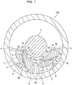
- a bearing 100 of the first embodiment is configured to be a journal bearing that rotatably supports a rotating shaft 1, which rotates in the direction of arrow A (hereinafter the direction is also called the rotating direction), from the radius direction.
- the bearing 100 includes multiple (two in this example) tilting pads (bearing pad of the first embodiment) 2 that support the rotating shaft 1 in the vertically upward direction, a bearing housing 4 arranged around the rotating shaft 1 and the tilting pads 2, and oil supply nozzles 6 that each sprays lubricant oil from the ejector 6a disposed at the tip of the nozzle 6.
- multiple (two in this example) pivots 5 are installed, which swingably support the respective tilting pads 2.
- Two oil supply nozzles 6 are provided for each tilting pad 2. Specifically, one oil supply nozzle 6 is arranged at the forward portion (i.e., an upstream portion of the rotating direction A of the rotating shaft 1) and the other is arranged at the backward portion (i.e., a downstream portion of the rotating direction A of the rotating shaft 1).
- the additional lubricant oil sprayed from the ejectors 6a of the respective oil supply nozzles 6 forms an oil film between the circumference surface (supported surface, hereinafter also called a rotating shaft circumference surface) 1a of the rotating shaft 1 and a sliding surface (hereinafter also called a pad sliding surface) 2a of a tilting pad 2 opposing to the rotating shaft circumference surface 1a.
- a conduit 3 is formed so as to connect a first aperture (hereinafter also called aperture or inlet) 3a formed on the sliding surface 2a to a second aperture (hereinafter also called aperture or exit) 3d formed on the back surface (surface on the opposite side of the sliding surface 2a and opposing to the bearing housing 4) 3d.
- the conduit 3 is divided into two parts of a path 3b towards the sliding surface 2a and a path 3c towards the back surface 2b that have different angles and therefor the conduit 3 bends.
- the first aperture 3a of the conduit 3 is arranged within the high temperature zone 2H that is also a high pressure zone while the second aperture 3d of the conduit 3 is arranged on the pad back surface 2b.
- the lubricant oil near the second aperture 3d on the pad back surface 2b is lower in temperature and pressure than that near the first aperture 3a (than the lubricant oil in the state of being pressurized and evolving heat between circumference surface 1a and sliding surface 2a) and has a pressure close to atmospheric pressure.
- the oil pressure near the first aperture 3a on the sliding surface 2a has a large differential pressure from the oil pressure near the second aperture 3d on the pad back surface 2b.
- This differential pressure lets the lubricant oil spontaneously flow through the conduit 3 in the direction of the arrow a from the first aperture 3a as the inlet to the second aperture 3d as the exit.
- the conduit 3 functions as an oil extraction hole.
- FIGs. 2A and 2B Multiple lines appearing on the tilting pad 2 in FIGs. 2A and 2B are isotherms that connect points having respective temperatures ta to tk attached to the respective lines when the tilting pad 2 is assumed not to have the conduit 3 ( FIG. 2B illustrates only an isotherm of the temperature ta on the sliding surface 2a and isotherms of the temperatures ti and tj on the pad back surface 2b).
- the temperatures ta to tk represent higher temperatures in the descending order. Namely, among the temperatures ta to tk, the temperature ta is the highest while the temperature tk is the lowest.
- a high temperature zone here, a zone surrounded by the isotherm of temperature ta and having a temperature ta or higher
- 2H including a point having the highest temperature lies at the pad rear portion (i.e., downstream direction along the rotating direction) 2c on the sliding surface 2a.
- the high temperature zone 2H lies at the pad rear portion 2c of the sliding surface 2a as the above description for the following reasons.
- the lubricant oil (lubricant oil film) being pressurized between the rotating shaft circumference surface 1a and the tilting pad 2 has an oil pressure (hereinafter also called oil film pressure) much higher than the oil pressure on the pad back surface 2b as described above, and above all has a particularly high oil film pressure at the pad rear portion 2c.
- oil film pressure oil pressure
- the orientation of the tilting pad 2 keeps its balance in the state of tilting (namely, the tilting pad 2 comes closer to the circumference surface 1a at the pad rear portion 2c, that is the downstream portion with respect to the rotating direction A, while comes apart from the circumference surface 1a at a pad forward portion 2d, that is the upstream portion with respect to the rotating direction A).
- 2A represents the oil film pressure P, which comes to be the minimum in the vicinity of the atmospheric pressure at the inlet (front edge) and the exit (rear edge) and comes to be the maximum at the pad rear portion 2c, where the space between the circumference surface 1a and the sliding surface 2a is narrow to make the oil film thin.
- the temperature of the lubricant oil film and the temperature of the tilting pad 2 which are assumed not to form the conduit 3 therein have a high temperature zone 2H at the pad rear portion 2c of the sliding surface 2a.
- the maximum value of the oil film pressure P lies within a range of 70-90 % of the length Lt (see FIG. 2B ) from the upstream edge 2e to the downstream edge 2g.
- the temperature of the sliding surface 2a rises as the oil film pressure P rises, and the highest temperature on the sliding surface 2a is expected to lie within a range of 70-100 % of the length Lt from the upstream edge 2e. Accordingly, it is satisfactory that the high temperature zone 2H is in the range of 70-100 % of the length Lt of the sliding surface 2a and the inlet 3a is formed in this range.
- the high temperature zone 2H may be determined by estimating, through experiment or simulation, a zone having a high possibility of including the highest temperature portion for each bearing and the inlet 3a may be set within the estimated high temperature zone 2H. Otherwise, a point having the highest temperature may be estimated through experiment or simulation and the inlet 3a of the conduit 3 may be set at this estimated point.
- multiple conduits 3 are arranged across the width direction (hereinafter called pad width direction) of the tilting pad 2 so as to cover substantially entire position of high temperature zone 2H spreading across the pad width direction.
- the conduit 3 consists of the paths 3b, 3c having different angles.
- the upstream path 3b which passes through the high temperature zone 2H extends in a direction substantially along the thickness direction (hereinafter also called pad thickness direction) of the tilting pad 2 while the downstream path 3c extends in a direction substantially along the front-rear direction (hereinafter also called pad front-rear direction) of the tilting pad 2.
- the tilting pad 2 has a temperature distribution that lowers in a direction substantially along the pad thickness direction around the high temperature zone 2H and lowers in a direction substantially along the pad front-rear direction in the remaining zone, and therefore the conduit 3 is formed to let the lubricant oil flow to conform such a temperature distribution. Namely, since lubricant oil, which carries heat, moves from a higher-temperature side to a lower-temperature side by the path 3b around the high temperature zone 2H and by the path 3c around the remaining zone, so that the temperature of the tilting pad 2 can be efficiently made uniform.
- the conduit 3 is formed into a straight line connecting the inlet 3a to the exit 3b, the conduit 3 at the high temperature zone 2H lies in a shallow position from the sliding surface 2a.
- This structure has a possibility of lowering the strength of the tilting pad 2 at the high temperature side, which requires further rigidness.
- the conduit 3 is bent also to avoid this inconvenience.
- the conduit 3 may be formed into a straight line connecting the inlet 3a to the exit 3b.
- the conduit 3 having a bent structure requires two processes of drilling from the inlet 3a and drilling from the exit 3b (sic) .
- forming the straight-line conduit 3 can be completed through a single process of drilling from either the inlet 3a or the exit3d.
- the paths 3b, 3c may be formed to have a curved connection therebetween. Also in this case, using a bendable drilling rod electrode makes it possible to form a curved conduit in a single process of drilling from either the inlet 3a or the exit 3d.
- An excessively large diameter of the conduit 3 may affect formation of the oil film pressure between the pad sliding surface 2a and the circumference surface 1a, and therefore a preferable diameter of the conduit 3 is equal to or less than 5 % of the size of the pad width.
- the conduit 3 has the inlet 3a arranged within the high temperature zone 2H that is also a high pressure zone and the exit 3d is opened to the pad back surface 2b of the low temperature zone that is a low pressure zone having the substantially atmospheric pressure.
- the conduit 3 consequently has a large differential pressure between the inlet 3a and the exit 3d to let the lubricant oil spontaneously flow through the conduit 3 in the direction of the arrow a. At that time, the flowing lubricant oil moves heat in the high temperature zone 2H to the low temperature side.
- the presence of the conduit 3 lowers the temperature at the pad rear portion 2c accommodating the high temperature zone 2H of the tilting pad 2 and also raises the temperature at the pad forward portion 2d lower in temperature than the pad rear portion 2c so that the temperature of the tilting pad 2 is made uniform as compared with a tilting pad not having a conduit 3. Consequently, the tilting pad 2 can be escaped from locally having a high temperature portion and the highest temperature can be lowered. This can suppress thermal deformation accompanied by differential thermal expansion and therefore can eliminate the requirement of using expensive material having a high terminal conductivity for the bearing pad.
- the differential pressure is used to let the lubricant oil flow through the conduit 3 to make the temperature of the tilting pad 2 uniform.
- This structure can eliminate the requirement for a pump to let the lubricant oil flow through the conduit 3.
- letting the lubricant oil flow through the conduit 3 avoids locally raising the temperature of the tilting pad 2 and also lowers the highest temperature of the tilting pad 2.
- This structure can eliminate the requirement to prepare a low-temperature additional oil for the purpose of cooling in addition to the lubricant oil.
- a tilting pad having a larger spring constant bounces the rotating shaft 1 and makes it difficult to absorb the vibration.
- a tilting pad having a larger attenuation coefficient more absorbs the vibration of the rotating shaft 1 to cease the vibration more rapidly. Inhibiting deformation of the tilting pad 2 can keep the attenuation coefficient to be high as compared with a traditional tilting pad not being inhibited from being deformed but even having an equivalent sprint constant.
- the hot lubricant oil heated by the friction loss between the rotating shaft circumference surface 1a and the sliding surface 2a does not re-flow onto the sliding surface 2a after passing through the exit 3d.
- the hot lubricant oil does not re-flow onto the sliding surface 2a, the low-temperature additional lubricant oil (additional oil) supplied from each oil supply nozzle 6 is not inhibited from flowing into the sliding surface 2a. Accordingly, rising the temperature of the rotating shaft 1 and the tilting pad 2 can be advantageously avoided.
- the bearing device according to the second embodiment of the present invention uses tilting pads (bearing pads according to the second embodiment of the present invention) 2A illustrated in FIGs. 3A and 3B in the bearing of the first embodiment.
- the tilting pad 2A of the second embodiment is different from the tilting pad 2 of the first embodiment in the point that the tilting pad 2A arranges the exit 3d of the conduit 3A on the front surface (hereinafter called tilting pad front surface) 2g of the tilting pad 2A pointing towards the upstream of rotating direction A while the tilting pad 2 of the first embodiment arranges the exit 3d of the conduit 3 on the pad back surface 2b.
- tilting pad front surface the tilting pad front surface
- the structure of the conduit 3A will now be further detailed by comparing the conduit 3 of the first embodiment.
- the path 3b from the inlet 3a (the pad sliding surface 2a side) of the conduit 3A is the same as the first embodiment, but the path 3c to the exit 3d lies shallower than the path 3c of the first embodiment (in other words, the path 3c of the second embodiment runs more parallel with the front-rear direction of the pad). Accordingly, this arranges the exit 3d of the end of the path 3c on the front surface 2g, not on the pad back surface 2b.
- the conduit 3A may take a form of a straight line that connects the inlet 3a to the exit 3d if the structure rigidness permits, and further alternatively, the conduit 3A may have a curved connection between the paths 3b and 3c as illustrated by the two-dotted line in FIG. 3A .
- the journal bearing and the tilting pad 2A of the second embodiment arranges the exit 3d of the conduit 3A on the pad front surface 2g around which the oil pressure is in the same extent as the atmospheric pressure.
- This structure allows the hot lubricant oil to spontaneously flow from the inlet 3a high in temperature and pressure to the exit 3d low in temperature and pressure, so that the same effects and advantages as the first embodiment can be obtained.
- the exit 3d of the conduit 3A is arranged on the pad front surface 2g, which can widen the area of the tilting pad through which the conduit passes as compared with the structure in which the exit 3d is arranged on the pad back surface 2b. This makes the temperature of the tilting pad 2A uniform over the wider area.
- a bearing 200 of the third embodiment takes a form of a thrust bearing that supports a rotating shaft 21 that rotates in the direction (hereinafter called rotating direction) indicated by the arrow A from the axis direction of the rotating shaft 21.
- the bearing 200 includes tilting pads (bearing pads of the third embodiment) 22 that rotatably support a thrust collar (supported portion) 21a in the form of a flange portion of the rotating shaft 21 from the axis direction of the rotating shaft 21, a bearing housing 24 arranged around the rotating shaft 21 and tilting pads 22, and oil supply nozzles 26 that spray lubricant oil from the respective ejectors 26a at the tips of the nozzles.
- tilting pads bearing pads of the third embodiment 22 that rotatably support a thrust collar (supported portion) 21a in the form of a flange portion of the rotating shaft 21 from the axis direction of the rotating shaft 21, a bearing housing 24 arranged around the rotating shaft 21 and tilting pads 22, and oil supply nozzles 26 that spray lubricant oil from the respective ejectors 26a at the tips of the nozzles.
- the tilting pads 22 are arranged on the both sides of the thrust collar 21a along the axis direction. Specifically, multiple (in this example, twelve) tilting pads 22 are arranged around the entire circumference of each side of the thrust collar (supported portion) 21a. On the back surface (hereinafter also called pad back surface) 22b of the each tilting pad 22, a pivot 25 is arranged to make the tilting pad 2 swingably.
- the oil supply nozzles 26 are alternately arranged with the tilting pads 22 and spray the lubricant oil (additional oil) from the ejectors 26a thereof to form an oil film between the thrust collar 21a serving as the supported portion and the sliding surfaces (hereinafter also called pad sliding surfaces) 22a of the tilting pads 22 opposing to the thrust collar 21a.
- the rotating shaft 21 is also supported by a journal bearing 300 as well as by the thrust bearing 200.
- the bearing housing 24 further includes one or more non-illustrated exhausting holes through which old lubricant oil is successively drained out in place of the additional oil fed from the oil supply nozzles 26.
- each tilting pad 22 includes a conduit 23 that runs from a first aperture (hereinafter also called aperture or inlet) 23a formed on the sliding surface 22a to a second aperture (hereinafter called aperture or exit) 23b formed on the back surface 22b.
- the conduit 23 here is formed into a straight line connecting the inlet 23a to the exit 23b.
- the inlet 23a is formed on a high-temperature zone 23H located in the rear portion (downstream portion of the rotating direction A) 22c on the pad sliding surface 22a while the exit 23b is formed in the forward portion (upstream portion of the rotating direction A) 22d on the pad back surface 22b.
- the inlet 3a is formed in this range.
- FIGs. 4A , 6A, and 6B designate same parts or elements between the third and fourth embodiments, so repetitious description is omitted here.
- the bearing according to the fourth embodiment takes a form of a thrust bearing as illustrated in FIG. 4A likewise the third embodiment.
- the fourth embodiment is different from that of the third embodiment only in the point of the structure of a tilting pad (bearing pad of the fourth embodiment of the present invention) 22A.
- the tilting pad 22A of this embodiment has an exit 23b of the conduit 23A formed at the front surface 22e of the tilting pad 22A while the exit 23b of the conduit 23 of the third embodiment is formed on the pad back surface 22b.
- the conduit 23A of the fourth embodiment takes the form of a straight line connecting the inlet 23a to the exit 23b.
- the tilting pads 2, 2A are arranged only below the rotating shaft 1.
- the tilting pads 2, 2A may be arranged around the entire circumference of the rotating shaft 1 including the upper side of the rotating shaft 1.
- the conduits 3, 3A there is no requirement to form the conduits 3, 3A in all the tilting pads 2, 2A, but it is satisfactory to form the conduits 3, 3A in at least lower tilting pads 2, 2A that are highly loaded.
- the conduits 23, 23A of the third and fourth embodiments each takes a form of straight lines.
- the conduits 23, 23A may be bent or curved to conform the inner temperature distribution of the tilting pads as carried out in the first and the second embodiments.
- the foregoing embodiments regard the range of 70-100 % of the length Lt from the frond edge of the pad sliding surface to be the high temperature zone.
- the high temperature zone is not limited to this.
- the downstream portion i.e., within a range of 50 % or more of the length Lt from the front edge of the pad sliding surface
- the foregoing embodiments arrange the exits (second apertures) upstream of the respective inlets (first apertures) in the rotating direction of the rotating shaft.
- the arrangement of the first and second apertures is not limited to this.
- the exit of the conduit may be arranged at the same position as the inlet with respect to the rotating direction of the rotating shaft.
- the bearing of the present invention provides a conduit passing through the high temperature zone and a zone of lower temperature than that of the high temperature zone in a bearing pad, so that the heat that would remain in the high-temperature zone if the conduit is absent is moved to the other zone to lower the highest temperature of the bearing pad to finally make the temperature in the bearing pad uniform.
- any zone that can let the lubricant oil flow through the conduit by using differential pressure and is relatively higher in temperature than the remaining zone through which the conduit passes i.e., a zone peripheral to the conduit
Landscapes
- Engineering & Computer Science (AREA)
- General Engineering & Computer Science (AREA)
- Mechanical Engineering (AREA)
- Chemical & Material Sciences (AREA)
- Oil, Petroleum & Natural Gas (AREA)
- Physics & Mathematics (AREA)
- Fluid Mechanics (AREA)
- Sliding-Contact Bearings (AREA)
- Mounting Of Bearings Or Others (AREA)
Claims (4)
- Lager, das eine Drehwelle (1, 21) mittels eines oder mehrerer Lagerplatten (2A, 22A) stützt und das mit einem Schmieröl zu einem Raum zwischen den Lagerplatten und einer gestützten Fläche (1a) der Drehwelle versorgt wird, wobei:mindestens eine der Lagerplatten (2A, 22A) eine Leitung (3A, 23A) umfasst, die sich von einer ersten Öffnung (3a, 23a), die an einer Hochtemperaturzone (2H, 22H) einer Schiebefläche (2a, 22a) gegenüber der gestützten Fläche (1a) gebildet ist, in einer Richtung weg von der gestützten Fläche erstreckt und die eine zweite Öffnung (3d, 23b) erreicht;jede der Lagerplatten zu einer Drehrichtung der Drehwelle hin neigbar ist;die Hochtemperaturzone bei einem Lagerplattenrückseitenabschnitt im stromabwärtigen Bereich der Schiebefläche in Bezug auf die Drehrichtung der Welle positioniert ist und die zweite Öffnung an einem Lagerplattenvorderabschnitt stromaufwärts der ersten Öffnung (3a, 23a) in Bezug auf die Drehrichtung positioniert ist; unddie Leitung (3A, 23A) ein Strömungspfad ist, der die erste Öffnung (3a, 23a) als einen Einlass und die zweite Öffnung (3d, 23b) als einen Ausgang aufweist und einen Differenzdruck aufweist, der das Schmieröl dort hindurch strömen lässt,dadurch gekennzeichnet, dassdie zweite Öffnung (3d, 23b) an einer Vorderfläche (2g, 22e) der mindestens einen der Lagerplatten (2A, 22A) angeordnet ist, die stromaufwärts der Drehrichtung zeigt.
- Lager nach Anspruch 1, wobei die Hochtemperaturzone (2H, 22H) innerhalb einer Spanne von 70-100 % einer Länge der Schiebefläche (2a, 22a) von einer stromaufwärtigen Kante der Schiebefläche (2a, 22a) in Bezug auf die Drehrichtung liegt.
- Lager nach einem der Ansprüche 1-2, wobei die gestützte Fläche (1a) eine Umfangsfläche entlang einer Radiusrichtung der Drehwelle (1, 21) ist.
- Lager nach einem der Ansprüche 1-2, wobei:die Drehwelle (1, 21) einen Druckring (200) umfasst, der sich in einer Radiusrichtung der Drehwelle nach außen erstreckt; unddie gestützte Fläche (1a) eine Endfläche des Druckrings zu einer Achsrichtung der Drehwelle (1, 21) hin ist.
Applications Claiming Priority (2)
| Application Number | Priority Date | Filing Date | Title |
|---|---|---|---|
| JP2014192545A JP6038088B2 (ja) | 2014-09-22 | 2014-09-22 | 軸受及び軸受パッド |
| PCT/JP2015/053805 WO2016047159A1 (ja) | 2014-09-22 | 2015-02-12 | 軸受及び軸受パッド |
Publications (3)
| Publication Number | Publication Date |
|---|---|
| EP3203096A1 EP3203096A1 (de) | 2017-08-09 |
| EP3203096A4 EP3203096A4 (de) | 2018-10-10 |
| EP3203096B1 true EP3203096B1 (de) | 2019-12-25 |
Family
ID=55580703
Family Applications (1)
| Application Number | Title | Priority Date | Filing Date |
|---|---|---|---|
| EP15808068.9A Active EP3203096B1 (de) | 2014-09-22 | 2015-02-12 | Lager und lagerplatte |
Country Status (6)
| Country | Link |
|---|---|
| US (1) | US9759257B2 (de) |
| EP (1) | EP3203096B1 (de) |
| JP (1) | JP6038088B2 (de) |
| KR (1) | KR101834626B1 (de) |
| CN (1) | CN105658973B (de) |
| WO (1) | WO2016047159A1 (de) |
Families Citing this family (17)
| Publication number | Priority date | Publication date | Assignee | Title |
|---|---|---|---|---|
| JP6709061B2 (ja) * | 2016-02-04 | 2020-06-10 | 三菱重工コンプレッサ株式会社 | ティルティングパッドガス軸受 |
| JP6920026B2 (ja) * | 2016-02-29 | 2021-08-18 | 三菱パワー株式会社 | ジャーナル軸受および回転機械 |
| DE102016206139A1 (de) * | 2016-04-13 | 2017-10-19 | Robert Bosch Gmbh | Vorrichtung mit einem Reibkontakt und Verfahren zum Betreiben einer Vorrichtung mit einem Reibkontakt |
| KR102693337B1 (ko) * | 2016-11-08 | 2024-08-08 | 한화파워시스템 주식회사 | 트레일링 에지에 홈이 형성된 틸팅 패드 저널 베어링 |
| KR102777759B1 (ko) * | 2017-02-21 | 2025-03-10 | 한화파워시스템 주식회사 | 틸팅 패드 저널 베어링 |
| WO2018217794A1 (en) | 2017-05-22 | 2018-11-29 | Waukesha Bearings Corporation | Bearing monitoring/analysis system |
| CN107191489A (zh) * | 2017-07-12 | 2017-09-22 | 哈尔滨理工大学 | 一种可控可调式推力轴承装置 |
| DE102018202465A1 (de) * | 2018-02-19 | 2019-08-22 | Siemens Aktiengesellschaft | Rotorlagerung mit Kühlung |
| DE102018216055A1 (de) * | 2018-09-20 | 2020-03-26 | Siemens Aktiengesellschaft | Lagerstein |
| IT201900007995A1 (it) | 2019-06-04 | 2020-12-04 | Nuovo Pignone Tecnologie Srl | Un cuscinetto con tacchetti aventi al proprio interno micro-canali di refrigerazione e metodo |
| CN110529500A (zh) * | 2019-08-20 | 2019-12-03 | 东方电气集团东方汽轮机有限公司 | 一种带轴向回油槽直接润滑可倾瓦轴承 |
| CN111120504A (zh) * | 2019-12-27 | 2020-05-08 | 西安交通大学 | 一种自反馈调节热变形的高承载推力滑动轴承 |
| JP7588499B2 (ja) * | 2020-11-26 | 2024-11-22 | 三菱重工業株式会社 | 軸受パッド、及び軸受装置 |
| DE102021124857A1 (de) | 2021-09-27 | 2023-03-30 | Voith Patent Gmbh | Kippsegmentlager, insbesondere Radialkippsegmentgleitlager |
| US12135057B2 (en) | 2022-08-31 | 2024-11-05 | Elliott Company | Tilt pad journal bearing with lubrication arrangement |
| US12247617B2 (en) | 2022-12-08 | 2025-03-11 | Hamilton Sundstrand Corporation | Cavitation resistant journal bearing |
| CN116498654B (zh) * | 2023-04-28 | 2025-11-18 | 东方电气集团东方电机有限公司 | 轴瓦组件及推力轴承 |
Family Cites Families (33)
| Publication number | Priority date | Publication date | Assignee | Title |
|---|---|---|---|---|
| US2363260A (en) * | 1941-10-10 | 1944-11-21 | American Steel & Wire Co | Bearing for rope stranding machines |
| US3004804A (en) | 1959-08-26 | 1961-10-17 | Gen Electric | Pivoted shoe bearing with force-feed lubrication |
| US3339990A (en) * | 1964-07-13 | 1967-09-05 | Worthington Corp | Lubricated bearing shoe |
| GB1199147A (en) * | 1966-09-26 | 1970-07-15 | Glacier Co Ltd | Thrust Bearing Assemblies |
| JPS4981742A (de) * | 1972-12-13 | 1974-08-07 | ||
| AR195103A1 (es) * | 1973-03-07 | 1973-09-10 | Atencio F | Un cojinete de empuje con congelacion del lubricante |
| CH550340A (de) * | 1973-10-11 | 1974-06-14 | Sulzer Ag | Gasgeschmiertes, selbst druckerzeugendes radiallager. |
| US3887249A (en) * | 1974-04-08 | 1975-06-03 | Allis Chalmers | Journal bearing for supporting both radial loads and axial thrust loads |
| US3893737A (en) * | 1974-04-19 | 1975-07-08 | Marchem Resources Inc | Thrust bearing having lubrication system |
| JPS5316750U (de) * | 1976-07-23 | 1978-02-13 | ||
| DE2931383A1 (de) * | 1979-08-02 | 1981-02-19 | Polysius Ag | Hydrodynamisches lager |
| US4413864A (en) * | 1981-07-31 | 1983-11-08 | Optimetrix Corporation | Gas bearing |
| IL97378A (en) * | 1990-03-08 | 1994-04-12 | Plastic Bearings & Housings Au | Bearing assemblies |
| US6499883B2 (en) * | 1997-03-31 | 2002-12-31 | Whm Holding Corporation | Tilting pad for bearings |
| US6200034B1 (en) * | 1997-03-31 | 2001-03-13 | Whm Holding Corporation | Self-stabilizing, true-tilting pad with generally tapered pocket for journal bearing |
| AT407404B (de) * | 1998-07-29 | 2001-03-26 | Miba Gleitlager Ag | Zwischenschicht, insbesondere bindungsschicht, aus einer legierung auf aluminiumbasis |
| JP2001200847A (ja) * | 1999-11-08 | 2001-07-27 | Mitsubishi Heavy Ind Ltd | 軸受装置、及び、タービン |
| CA2324322C (en) * | 2000-10-26 | 2008-12-30 | General Electric Canada Inc. | Thrust bearing |
| US6739756B2 (en) * | 2001-03-12 | 2004-05-25 | Whm Holding Corporation | Combination thrust bearing and journal bearing, and method for distributing fluid to same |
| US6485182B2 (en) * | 2001-03-28 | 2002-11-26 | Rotating Machinery Technology, Inc. | Sleeve bearing with bypass cooling |
| US20050047690A1 (en) * | 2003-08-27 | 2005-03-03 | General Electric Company | Bearing assembly with fluid circuit for delivery of lubricating fluid between bearing surfaces |
| US7758247B2 (en) * | 2005-02-28 | 2010-07-20 | Kingsbury, Inc. | Journal bearing having surface-contact retained shoes |
| EP2002136A1 (de) * | 2006-03-31 | 2008-12-17 | Alstom Technology Ltd | Hydrodynamisches axialgleitlager und zugehöriges betriebsverfahren |
| JP4930290B2 (ja) | 2007-09-04 | 2012-05-16 | 株式会社日立プラントテクノロジー | ティルティングパッド型ジャーナル軸受 |
| JP2010151292A (ja) * | 2008-12-26 | 2010-07-08 | Ihi Corp | ティルティングパッド軸受 |
| IT1395717B1 (it) * | 2009-09-22 | 2012-10-19 | Nuovo Pignone Spa | Cuscinetto, meccanismo di distribuzione olio e metodo. |
| WO2012114445A1 (ja) * | 2011-02-21 | 2012-08-30 | 株式会社日立製作所 | ティルティングパッド型ジャーナル軸受及びこれを備えた回転機械 |
| EP2758679A4 (de) * | 2011-09-21 | 2016-01-20 | Dresser Rand Co | Kippsegmentlager mit schwenkschmierung |
| AU2012318550B2 (en) * | 2011-10-06 | 2016-04-14 | Telsmith, Inc. | Apparatus and method for a bearing assembly system |
| EP2669537A1 (de) * | 2012-06-01 | 2013-12-04 | Alstom Technology Ltd. | Radiales Segmentlager für Turbine |
| JP2014119080A (ja) * | 2012-12-19 | 2014-06-30 | Hitachi Ltd | すべり軸受装置 |
| KR101676987B1 (ko) * | 2013-01-31 | 2016-11-16 | 미츠비시 히타치 파워 시스템즈 가부시키가이샤 | 틸팅 패드 베어링 장치 |
| JP6412788B2 (ja) * | 2014-12-10 | 2018-10-24 | 三菱日立パワーシステムズ株式会社 | ティルティングパッド軸受 |
-
2014
- 2014-09-22 JP JP2014192545A patent/JP6038088B2/ja active Active
-
2015
- 2015-02-12 WO PCT/JP2015/053805 patent/WO2016047159A1/ja not_active Ceased
- 2015-02-12 EP EP15808068.9A patent/EP3203096B1/de active Active
- 2015-02-12 CN CN201580000980.8A patent/CN105658973B/zh active Active
- 2015-02-12 KR KR1020157036353A patent/KR101834626B1/ko active Active
- 2015-02-12 US US14/392,311 patent/US9759257B2/en active Active
Non-Patent Citations (1)
| Title |
|---|
| None * |
Also Published As
| Publication number | Publication date |
|---|---|
| JP6038088B2 (ja) | 2016-12-07 |
| US9759257B2 (en) | 2017-09-12 |
| WO2016047159A1 (ja) | 2016-03-31 |
| CN105658973A (zh) | 2016-06-08 |
| KR20160052464A (ko) | 2016-05-12 |
| JP2016061430A (ja) | 2016-04-25 |
| EP3203096A1 (de) | 2017-08-09 |
| EP3203096A4 (de) | 2018-10-10 |
| CN105658973B (zh) | 2018-02-13 |
| KR101834626B1 (ko) | 2018-03-05 |
| US20160265590A1 (en) | 2016-09-15 |
Similar Documents
| Publication | Publication Date | Title |
|---|---|---|
| EP3203096B1 (de) | Lager und lagerplatte | |
| CN101563547B (zh) | 用于大型涡轮机组的承载能力极高的液力的向心滑动轴承 | |
| JP6412788B2 (ja) | ティルティングパッド軸受 | |
| US8845282B2 (en) | Seal plate with cooling passage | |
| JP4604099B2 (ja) | ジャーナル軸受装置 | |
| CN109952443B (zh) | 可倾瓦轴承和其制造方法 | |
| US10359072B2 (en) | Journal bearing and rotary machine | |
| CN102667269B (zh) | 迷宫式密封装置和用于制造迷宫式密封装置的方法 | |
| JPH07293554A (ja) | ティルティングパッド型軸受装置 | |
| JP2015007463A (ja) | ティルティングパッド軸受 | |
| US20040057642A1 (en) | Thrust bearing arrangement | |
| JP4559781B2 (ja) | 蒸気タービンケーシングおよび蒸気タービン | |
| JP6332919B2 (ja) | ティルティングパッド軸受装置 | |
| JP5094833B2 (ja) | ティルティングパッドジャーナル軸受装置 | |
| KR102115856B1 (ko) | 저널 베어링 및 회전 기계 | |
| US20040032996A1 (en) | Reduced width tilting pad journal bearing and related method | |
| JP2003120675A (ja) | 軸受装置及び軸受装置の潤滑油供給量制御方法 | |
| JP6818668B2 (ja) | ティルティングパッドジャーナル軸受及びこれを用いた遠心圧縮機 | |
| WO2020021866A1 (ja) | ティルティングパッド型ジャーナル軸受及びそれを用いた回転機械 | |
| US11828331B2 (en) | Bearing with pads having cooling micro-channels therein, and method | |
| JP2006138353A (ja) | すべり軸受及びすべり軸受を備えた回転電機 | |
| JP2016217398A (ja) | 軸受装置 | |
| JP5602122B2 (ja) | すべり軸受とそれを用いたポンプ装置 | |
| JP6798950B2 (ja) | ティルティングパッドジャーナル軸受装置 | |
| JP5978946B2 (ja) | 過給機 |
Legal Events
| Date | Code | Title | Description |
|---|---|---|---|
| PUAI | Public reference made under article 153(3) epc to a published international application that has entered the european phase |
Free format text: ORIGINAL CODE: 0009012 |
|
| STAA | Information on the status of an ep patent application or granted ep patent |
Free format text: STATUS: REQUEST FOR EXAMINATION WAS MADE |
|
| 17P | Request for examination filed |
Effective date: 20151222 |
|
| AK | Designated contracting states |
Kind code of ref document: A1 Designated state(s): AL AT BE BG CH CY CZ DE DK EE ES FI FR GB GR HR HU IE IS IT LI LT LU LV MC MK MT NL NO PL PT RO RS SE SI SK SM TR |
|
| AX | Request for extension of the european patent |
Extension state: BA ME |
|
| DAX | Request for extension of the european patent (deleted) | ||
| A4 | Supplementary search report drawn up and despatched |
Effective date: 20180912 |
|
| RIC1 | Information provided on ipc code assigned before grant |
Ipc: F16C 17/03 20060101AFI20180906BHEP Ipc: F16C 37/00 20060101ALI20180906BHEP Ipc: F16C 17/06 20060101ALI20180906BHEP Ipc: F16C 33/10 20060101ALI20180906BHEP |
|
| STAA | Information on the status of an ep patent application or granted ep patent |
Free format text: STATUS: EXAMINATION IS IN PROGRESS |
|
| 17Q | First examination report despatched |
Effective date: 20190405 |
|
| GRAP | Despatch of communication of intention to grant a patent |
Free format text: ORIGINAL CODE: EPIDOSNIGR1 |
|
| STAA | Information on the status of an ep patent application or granted ep patent |
Free format text: STATUS: GRANT OF PATENT IS INTENDED |
|
| INTG | Intention to grant announced |
Effective date: 20190822 |
|
| RIN1 | Information on inventor provided before grant (corrected) |
Inventor name: SANO, TAKESHI |
|
| GRAS | Grant fee paid |
Free format text: ORIGINAL CODE: EPIDOSNIGR3 |
|
| GRAA | (expected) grant |
Free format text: ORIGINAL CODE: 0009210 |
|
| STAA | Information on the status of an ep patent application or granted ep patent |
Free format text: STATUS: THE PATENT HAS BEEN GRANTED |
|
| AK | Designated contracting states |
Kind code of ref document: B1 Designated state(s): AL AT BE BG CH CY CZ DE DK EE ES FI FR GB GR HR HU IE IS IT LI LT LU LV MC MK MT NL NO PL PT RO RS SE SI SK SM TR |
|
| REG | Reference to a national code |
Ref country code: GB Ref legal event code: FG4D |
|
| REG | Reference to a national code |
Ref country code: CH Ref legal event code: EP |
|
| REG | Reference to a national code |
Ref country code: AT Ref legal event code: REF Ref document number: 1217440 Country of ref document: AT Kind code of ref document: T Effective date: 20200115 |
|
| REG | Reference to a national code |
Ref country code: DE Ref legal event code: R096 Ref document number: 602015044378 Country of ref document: DE |
|
| REG | Reference to a national code |
Ref country code: IE Ref legal event code: FG4D |
|
| REG | Reference to a national code |
Ref country code: NL Ref legal event code: MP Effective date: 20191225 |
|
| PG25 | Lapsed in a contracting state [announced via postgrant information from national office to epo] |
Ref country code: LT Free format text: LAPSE BECAUSE OF FAILURE TO SUBMIT A TRANSLATION OF THE DESCRIPTION OR TO PAY THE FEE WITHIN THE PRESCRIBED TIME-LIMIT Effective date: 20191225 Ref country code: FI Free format text: LAPSE BECAUSE OF FAILURE TO SUBMIT A TRANSLATION OF THE DESCRIPTION OR TO PAY THE FEE WITHIN THE PRESCRIBED TIME-LIMIT Effective date: 20191225 Ref country code: BG Free format text: LAPSE BECAUSE OF FAILURE TO SUBMIT A TRANSLATION OF THE DESCRIPTION OR TO PAY THE FEE WITHIN THE PRESCRIBED TIME-LIMIT Effective date: 20200325 Ref country code: GR Free format text: LAPSE BECAUSE OF FAILURE TO SUBMIT A TRANSLATION OF THE DESCRIPTION OR TO PAY THE FEE WITHIN THE PRESCRIBED TIME-LIMIT Effective date: 20200326 Ref country code: NO Free format text: LAPSE BECAUSE OF FAILURE TO SUBMIT A TRANSLATION OF THE DESCRIPTION OR TO PAY THE FEE WITHIN THE PRESCRIBED TIME-LIMIT Effective date: 20200325 Ref country code: LV Free format text: LAPSE BECAUSE OF FAILURE TO SUBMIT A TRANSLATION OF THE DESCRIPTION OR TO PAY THE FEE WITHIN THE PRESCRIBED TIME-LIMIT Effective date: 20191225 Ref country code: SE Free format text: LAPSE BECAUSE OF FAILURE TO SUBMIT A TRANSLATION OF THE DESCRIPTION OR TO PAY THE FEE WITHIN THE PRESCRIBED TIME-LIMIT Effective date: 20191225 |
|
| REG | Reference to a national code |
Ref country code: LT Ref legal event code: MG4D |
|
| PG25 | Lapsed in a contracting state [announced via postgrant information from national office to epo] |
Ref country code: RS Free format text: LAPSE BECAUSE OF FAILURE TO SUBMIT A TRANSLATION OF THE DESCRIPTION OR TO PAY THE FEE WITHIN THE PRESCRIBED TIME-LIMIT Effective date: 20191225 Ref country code: HR Free format text: LAPSE BECAUSE OF FAILURE TO SUBMIT A TRANSLATION OF THE DESCRIPTION OR TO PAY THE FEE WITHIN THE PRESCRIBED TIME-LIMIT Effective date: 20191225 |
|
| PG25 | Lapsed in a contracting state [announced via postgrant information from national office to epo] |
Ref country code: AL Free format text: LAPSE BECAUSE OF FAILURE TO SUBMIT A TRANSLATION OF THE DESCRIPTION OR TO PAY THE FEE WITHIN THE PRESCRIBED TIME-LIMIT Effective date: 20191225 |
|
| PG25 | Lapsed in a contracting state [announced via postgrant information from national office to epo] |
Ref country code: RO Free format text: LAPSE BECAUSE OF FAILURE TO SUBMIT A TRANSLATION OF THE DESCRIPTION OR TO PAY THE FEE WITHIN THE PRESCRIBED TIME-LIMIT Effective date: 20191225 Ref country code: PT Free format text: LAPSE BECAUSE OF FAILURE TO SUBMIT A TRANSLATION OF THE DESCRIPTION OR TO PAY THE FEE WITHIN THE PRESCRIBED TIME-LIMIT Effective date: 20200520 Ref country code: CZ Free format text: LAPSE BECAUSE OF FAILURE TO SUBMIT A TRANSLATION OF THE DESCRIPTION OR TO PAY THE FEE WITHIN THE PRESCRIBED TIME-LIMIT Effective date: 20191225 Ref country code: NL Free format text: LAPSE BECAUSE OF FAILURE TO SUBMIT A TRANSLATION OF THE DESCRIPTION OR TO PAY THE FEE WITHIN THE PRESCRIBED TIME-LIMIT Effective date: 20191225 Ref country code: EE Free format text: LAPSE BECAUSE OF FAILURE TO SUBMIT A TRANSLATION OF THE DESCRIPTION OR TO PAY THE FEE WITHIN THE PRESCRIBED TIME-LIMIT Effective date: 20191225 |
|
| PG25 | Lapsed in a contracting state [announced via postgrant information from national office to epo] |
Ref country code: SK Free format text: LAPSE BECAUSE OF FAILURE TO SUBMIT A TRANSLATION OF THE DESCRIPTION OR TO PAY THE FEE WITHIN THE PRESCRIBED TIME-LIMIT Effective date: 20191225 Ref country code: IS Free format text: LAPSE BECAUSE OF FAILURE TO SUBMIT A TRANSLATION OF THE DESCRIPTION OR TO PAY THE FEE WITHIN THE PRESCRIBED TIME-LIMIT Effective date: 20200425 Ref country code: SM Free format text: LAPSE BECAUSE OF FAILURE TO SUBMIT A TRANSLATION OF THE DESCRIPTION OR TO PAY THE FEE WITHIN THE PRESCRIBED TIME-LIMIT Effective date: 20191225 |
|
| REG | Reference to a national code |
Ref country code: DE Ref legal event code: R097 Ref document number: 602015044378 Country of ref document: DE |
|
| REG | Reference to a national code |
Ref country code: CH Ref legal event code: PL |
|
| REG | Reference to a national code |
Ref country code: BE Ref legal event code: MM Effective date: 20200229 |
|
| PG25 | Lapsed in a contracting state [announced via postgrant information from national office to epo] |
Ref country code: MC Free format text: LAPSE BECAUSE OF FAILURE TO SUBMIT A TRANSLATION OF THE DESCRIPTION OR TO PAY THE FEE WITHIN THE PRESCRIBED TIME-LIMIT Effective date: 20191225 Ref country code: ES Free format text: LAPSE BECAUSE OF FAILURE TO SUBMIT A TRANSLATION OF THE DESCRIPTION OR TO PAY THE FEE WITHIN THE PRESCRIBED TIME-LIMIT Effective date: 20191225 Ref country code: LU Free format text: LAPSE BECAUSE OF NON-PAYMENT OF DUE FEES Effective date: 20200212 Ref country code: DK Free format text: LAPSE BECAUSE OF FAILURE TO SUBMIT A TRANSLATION OF THE DESCRIPTION OR TO PAY THE FEE WITHIN THE PRESCRIBED TIME-LIMIT Effective date: 20191225 |
|
| PLBE | No opposition filed within time limit |
Free format text: ORIGINAL CODE: 0009261 |
|
| STAA | Information on the status of an ep patent application or granted ep patent |
Free format text: STATUS: NO OPPOSITION FILED WITHIN TIME LIMIT |
|
| REG | Reference to a national code |
Ref country code: AT Ref legal event code: MK05 Ref document number: 1217440 Country of ref document: AT Kind code of ref document: T Effective date: 20191225 |
|
| PG25 | Lapsed in a contracting state [announced via postgrant information from national office to epo] |
Ref country code: CH Free format text: LAPSE BECAUSE OF NON-PAYMENT OF DUE FEES Effective date: 20200229 Ref country code: SI Free format text: LAPSE BECAUSE OF FAILURE TO SUBMIT A TRANSLATION OF THE DESCRIPTION OR TO PAY THE FEE WITHIN THE PRESCRIBED TIME-LIMIT Effective date: 20191225 Ref country code: LI Free format text: LAPSE BECAUSE OF NON-PAYMENT OF DUE FEES Effective date: 20200229 |
|
| 26N | No opposition filed |
Effective date: 20200928 |
|
| PG25 | Lapsed in a contracting state [announced via postgrant information from national office to epo] |
Ref country code: IE Free format text: LAPSE BECAUSE OF NON-PAYMENT OF DUE FEES Effective date: 20200212 Ref country code: AT Free format text: LAPSE BECAUSE OF FAILURE TO SUBMIT A TRANSLATION OF THE DESCRIPTION OR TO PAY THE FEE WITHIN THE PRESCRIBED TIME-LIMIT Effective date: 20191225 Ref country code: IT Free format text: LAPSE BECAUSE OF FAILURE TO SUBMIT A TRANSLATION OF THE DESCRIPTION OR TO PAY THE FEE WITHIN THE PRESCRIBED TIME-LIMIT Effective date: 20191225 Ref country code: FR Free format text: LAPSE BECAUSE OF NON-PAYMENT OF DUE FEES Effective date: 20200225 |
|
| PG25 | Lapsed in a contracting state [announced via postgrant information from national office to epo] |
Ref country code: BE Free format text: LAPSE BECAUSE OF NON-PAYMENT OF DUE FEES Effective date: 20200229 Ref country code: PL Free format text: LAPSE BECAUSE OF FAILURE TO SUBMIT A TRANSLATION OF THE DESCRIPTION OR TO PAY THE FEE WITHIN THE PRESCRIBED TIME-LIMIT Effective date: 20191225 |
|
| GBPC | Gb: european patent ceased through non-payment of renewal fee |
Effective date: 20200325 |
|
| PG25 | Lapsed in a contracting state [announced via postgrant information from national office to epo] |
Ref country code: GB Free format text: LAPSE BECAUSE OF NON-PAYMENT OF DUE FEES Effective date: 20200325 |
|
| PG25 | Lapsed in a contracting state [announced via postgrant information from national office to epo] |
Ref country code: TR Free format text: LAPSE BECAUSE OF FAILURE TO SUBMIT A TRANSLATION OF THE DESCRIPTION OR TO PAY THE FEE WITHIN THE PRESCRIBED TIME-LIMIT Effective date: 20191225 Ref country code: MT Free format text: LAPSE BECAUSE OF FAILURE TO SUBMIT A TRANSLATION OF THE DESCRIPTION OR TO PAY THE FEE WITHIN THE PRESCRIBED TIME-LIMIT Effective date: 20191225 Ref country code: CY Free format text: LAPSE BECAUSE OF FAILURE TO SUBMIT A TRANSLATION OF THE DESCRIPTION OR TO PAY THE FEE WITHIN THE PRESCRIBED TIME-LIMIT Effective date: 20191225 |
|
| PG25 | Lapsed in a contracting state [announced via postgrant information from national office to epo] |
Ref country code: MK Free format text: LAPSE BECAUSE OF FAILURE TO SUBMIT A TRANSLATION OF THE DESCRIPTION OR TO PAY THE FEE WITHIN THE PRESCRIBED TIME-LIMIT Effective date: 20191225 |
|
| PGFP | Annual fee paid to national office [announced via postgrant information from national office to epo] |
Ref country code: DE Payment date: 20241231 Year of fee payment: 11 |