EP3202999B1 - Betätigungshandhabe und einsatzkörper für eine betätigungshandhabe - Google Patents
Betätigungshandhabe und einsatzkörper für eine betätigungshandhabe Download PDFInfo
- Publication number
- EP3202999B1 EP3202999B1 EP17152823.5A EP17152823A EP3202999B1 EP 3202999 B1 EP3202999 B1 EP 3202999B1 EP 17152823 A EP17152823 A EP 17152823A EP 3202999 B1 EP3202999 B1 EP 3202999B1
- Authority
- EP
- European Patent Office
- Prior art keywords
- handle
- contact area
- locking
- wear protection
- protection means
- Prior art date
- Legal status (The legal status is an assumption and is not a legal conclusion. Google has not performed a legal analysis and makes no representation as to the accuracy of the status listed.)
- Active
Links
Images


Classifications
-
- E—FIXED CONSTRUCTIONS
- E05—LOCKS; KEYS; WINDOW OR DOOR FITTINGS; SAFES
- E05B—LOCKS; ACCESSORIES THEREFOR; HANDCUFFS
- E05B15/00—Other details of locks; Parts for engagement by bolts of fastening devices
- E05B15/16—Use of special materials for parts of locks
- E05B15/1614—Use of special materials for parts of locks of hard materials, to prevent drilling
-
- E—FIXED CONSTRUCTIONS
- E05—LOCKS; KEYS; WINDOW OR DOOR FITTINGS; SAFES
- E05B—LOCKS; ACCESSORIES THEREFOR; HANDCUFFS
- E05B3/00—Fastening knobs or handles to lock or latch parts
-
- E—FIXED CONSTRUCTIONS
- E05—LOCKS; KEYS; WINDOW OR DOOR FITTINGS; SAFES
- E05B—LOCKS; ACCESSORIES THEREFOR; HANDCUFFS
- E05B3/00—Fastening knobs or handles to lock or latch parts
- E05B3/04—Fastening the knob or the handle shank to the spindle by screws, springs or snap bolts
-
- E—FIXED CONSTRUCTIONS
- E05—LOCKS; KEYS; WINDOW OR DOOR FITTINGS; SAFES
- E05B—LOCKS; ACCESSORIES THEREFOR; HANDCUFFS
- E05B3/00—Fastening knobs or handles to lock or latch parts
- E05B2003/006—Fastening knobs or handles to the spindle by means of tilt-plates
Definitions
- the invention relates to an operating handle according to the preamble of claim 1. Furthermore, the invention relates to an insert body for an operating handle according to the preamble of claim 13.
- Actuating handles are known in numerous configurations. They are used, for example, to open and close a window, a door or the like, with a handle mostly via a driver, e.g. a square pin is designed for the rotary entrainment of an actuating device in the window or door sash, such as a window gear or a lock nut.
- a driver e.g. a square pin is designed for the rotary entrainment of an actuating device in the window or door sash, such as a window gear or a lock nut.
- the driver In addition to the torque, the driver usually also has to transmit axial tensile forces, e.g. in the case of door fittings.
- the connection between the handle and the driver must be designed so that both are axially and non-rotatably anchored to one another after assembly, whereby - depending on the design of the window or the door - an adaptation of the pin connection to the respective thickness of the window frame or the door leaf must be possible.
- an actuating handle in which a device is provided between the handle and the driver element which allows a relative movement between the handle and the driver element in a first axial direction and blocks it in the opposite axial direction. This makes it possible to simply slide the handle onto the driver element which is inserted laterally into the door leaf and protrudes through a lock nut until the desired insertion depth is reached.
- a device is provided in the handle which has a locking or clamping element which is acted upon by a spring force and which can be brought into force, positive and / or frictional engagement with the driver element.
- the locking element can be designed as a locking frame which has an angular recess in the center through which the driver element can be guided, so that the locking frame encloses the driver element at least in sections.
- the locking effect is achieved in that the spring force presses the locking or clamping elements against a contact surface, so that the locking or clamping elements are tilted into an inclined position and the edges of the recess of the locking or clamping elements press against the driver element and thus an axial movement of the Lock the driver element in one direction.
- Similar devices are from the EP 2 241 704 A1 and the JP 2001 254538 A known.
- the disadvantage here is that the pivotably mounted locking or clamping elements are pressed directly onto the contact area by the spring force. If forces act on the locking device after installation and prolonged, intended use of the operating handle, ie the opening and closing of a door or window, the contact area of the locking or clamping elements can be severely worn. The cause of this wear and tear is that when tensile or compressive forces act, the locking or clamping elements move and rub on the contact area. The resulting wear can lead to a deterioration in the locking function. In particular, abrasion can lead to a change in the geometry of the contact area, so that the function of a stop, which enables the inclined position of the locking or clamping elements required for the locking effect, can no longer be fulfilled.
- the aim of the invention is to overcome these and other disadvantages of the prior art and to create an actuating handle that enables a tool-free and permanently reliable connection between the driver and the handle, with the locking effect being maintained even with prolonged and frequently repeated use of the actuating handle remains.
- a locking device being provided between the handle and the driver element, which is designed such that the introduction of the driver element into the handle can be brought about in a first direction and locked in the opposite direction, the locking device having at least one locking element which is acted upon by a spring force and which can be brought into force, positive and / or frictional engagement with the driver element is, wherein the locking element is designed as a locking frame that encloses the driver element at least in sections, and wherein the locking element is pivotably mounted and is supported on a contact area in the area of the handle, the invention provides that a coating or a separate body in the contact area a v wear-resistant and / or hardened material is arranged or designed as wear protection means, wherein the wear protection means has a different material than the contact area, and wherein the locking element is supported essentially on or on the wear protection means.
- the wear protection agent can be selected from higher quality materials with better wear protection properties.
- wear-resistant hard materials can also be used as material for the wear protection agent according to the invention.
- metallic hard materials such as carbides, nitrides, carbonitrides, borides and silicides of the transition metals, hard material mixed crystals (e.g. TiC-WC, TiC-TaC-WC, TiC-TiN), double carbides and complex carbides (e.g. Co 3 W 3 C, Ni 3 W 3 C) and intermetallic compounds (e.g. W-Co, W-Os, W-Re, W-Ir, Mo-Be).
- metallic hard materials such as carbides, nitrides, carbonitrides, borides and silicides of the transition metals
- hard material mixed crystals e.g. TiC-WC, TiC-TaC-WC, TiC-TiN
- double carbides and complex carbides e.g. Co 3 W 3 C, Ni 3 W 3 C
- intermetallic compounds e.g. W-Co, W-Os,
- the non-metallic hard materials are carbides, nitrides and oxides of main group elements and some modifications of the pure elements, such as natural and synthetic diamond, corundum (Al 2 O 3 ), natural and synthetic precious and semi-precious stones (e.g. sapphire, ruby, zircon), boron, Boron carbide (B 4 C), cubic boron nitride (BN, "Borazon”), beryllium carbide, silicon carbide (SiC), silicon nitride (Si 3 N 4 ) and aluminum nitride (AlN) are possible.
- Composite materials with high wear resistance that consist of more than just one material are also conceivable.
- a coating for the use of a coating as a wear protection agent, among other things, metal alloys are known as wear-resistant coatings. These alloys are applied to the base body by spraying or welding and adhere to it Fusion, adhesion or the formation of an intermediate layer. Applying the coating by painting is also conceivable.
- the advantage of the coating is that the coating can extend over the entire contact surface and thus its wear protection property is extended to the entire stressed surface. In addition, in the case of a coating, no additional spatial body has to be introduced into the device, which simplifies production and assembly.
- the blocking element When using a separate body as a wear protection means, the blocking element is essentially supported on this separate body, so that direct contact between the blocking element and the contact area is avoided and the contact area cannot be worn out.
- the body can be connected to the contact area, in particular by gluing or welding, so that a load-bearing connection can be achieved between the body and the wear protection means.
- the wear protection means is a separate body which is at least partially received in a bore in the contact area.
- the arrangement of the wear protection means can be determined by the arrangement of the bore. In this way, the installation of the wear protection means can be carried out relatively easily, and damaged wear protection means can be replaced in a simple manner. If the wear protection agent is to be permanently attached, this could be achieved, for example, by means of hot isostatic pressing with the contact area.
- the wear protection means is designed as a separate, rotationally symmetrical, in particular roller-shaped or spherically symmetrical body.
- the locking element thus has little or no contact with the contact area, which is usually made of zamak alloy in the zinc die-casting process and is therefore not very wear-resistant, so that wear on the contact surface is avoided.
- a spherical body as a wear protection means has the advantage that it offers only a small contact area for the locking element.
- the locking device is formed in the handle neck.
- the handle has a main handle part and a handle neck, the handle neck having a recess at the end and the locking device being formed in the recess. It is particularly advantageous if an insert body is inserted into the front side of the recess, the locking element being pressed by the spring force of a spring which is supported in the handle neck against the wear protection means which is arranged on the contact area. It is particularly advantageous if the contact area is formed on the insert body.
- the insert body is designed as a socket which is inserted in the recess in the handle neck, the locking element being arranged in the socket and the locking element being acted upon by the spring force of a spring which is arranged in the socket.
- the insert body with the locking device can be designed as a preassembled unit. This unit can then simply be screwed, glued or pressed into the handle neck of the handle. This not only simplifies warehousing but can also be installed in any door or window handle at the factory, depending on the customer's requirements.
- the contact area is formed by an inclined surface of the insert body. It is particularly advantageous if the direction of inclination of the inclined surface runs diagonally to the cross section of the driver element.
- the inclined surface ensures that the locking element always forms a maximally large lever arm.
- no separate support edge is required as an axis of rotation, so that the blocking element can be produced quickly and inexpensively, in particular by punching.
- the locking element is inclined to the axial direction and is at least on the edge of the wear protection means. In this way, the contact area between the wear protection means and the locking element can be additionally reduced while the locking effect remains the same.
- the abrasive forces only act on a particularly small, almost punctiform area of the wear protection agent.
- the invention relates to an insert body for an actuating handle which is fixed or fixable in a handle neck of the actuating handle, the insert body being designed as a socket which can be inserted at the end into the handle neck of an actuating handle, a locking device being formed in the insert body which has at least one locking element which is acted upon by a spring force and wherein the The locking element is designed as a locking frame and the locking element is pivotably mounted and is supported on a contact area in the interior of the socket, wherein according to the invention a wear protection agent is arranged in the contact area, the locking element being supported essentially on or on the wear protection agent.
- the wear protection agent forms part of the contact area on which the blocking element rests.
- the wear protection agent prevents direct contact between the blocking element and the contact area, so that wear and tear on the contact area can be prevented effectively and precisely. This leads to a longer service life of the plant area and to the preservation of its functionality. The durability of the locking effect is thus guaranteed even with prolonged and frequently repeated use of the actuating handle.
- the insert body can be prefabricated as a pre-encapsulated unit.
- An insert body designed as a socket in this way can be manufactured as an independent component and easily combined with handles to form an actuating handle. The unit can then simply be screwed, glued or pressed into the handle neck of the handle.
- Such an insert not only simplifies storage but can also be provided at the factory in any door or window handle, depending on the customer's requirements.
- the wear protection agent has a different material than the contact area. This allows the advantages of two different materials to be optimally used. While the contact area and the parts that form this contact area can be produced inexpensively and quickly by die casting from metal, in particular by zinc die casting, the wear protection agent can be selected from higher quality materials with better wear protection properties.
- the wear protection means can particularly advantageously consist of a hardened material and / or wear-resistant material.
- a targeted change and transformation of its structure increases the strength. This increase in strength brings with it a higher wear resistance, so that such a material, in particular a hardened metal such as hardened steel, can be used particularly effectively as a wear protection agent.
- wear-resistant hard materials can also be used as material for the wear protection agent according to the invention.
- metallic hard materials such as carbides, nitrides, carbonitrides, borides and silicides of transition metals, hard mixed crystals (e.g. TiC-WC, TiC-TaC-WC, TiC-TiN), double carbides and complex carbides (e.g. Co3W3C, Ni3W3C) and intermetallic compounds (e.g. W-Co, W-Os, W-Re, W -Ir, Mo-Be).
- metallic hard materials such as carbides, nitrides, carbonitrides, borides and silicides of transition metals, hard mixed crystals (e.g. TiC-WC, TiC-TaC-WC, TiC-TiN), double carbides and complex carbides (e.g. Co3W3C, Ni3W3C) and intermetallic compounds (e.g. W-Co, W-Os, W-Re, W
- the non-metallic hard materials are carbides, nitrides and oxides of main group elements and some modifications of the pure elements, such as natural and synthetic diamond, corundum (AI2O3), natural and synthetic precious and semi-precious stones (e.g. sapphire, ruby, zircon), boron, boron carbide (B4C ), cubic boron nitride (BN, "Borazon”), beryllium carbide, silicon carbide (SiC), silicon nitride (Si3N4) and aluminum nitride (AIN).
- Composite materials with high wear resistance that consist of more than just one material are also conceivable.
- the wear protection agent is a coating.
- Metal alloys are known as wear-resistant coatings. These alloys are applied to the base body by spraying or welding and adhere to it by fusing, by adhesion or by forming an intermediate layer. Applying the coating by painting is also conceivable.
- the advantage of the coating is that the coating can extend over the entire contact surface and thus its wear protection property is extended to the entire stressed surface. In addition, in the case of a coating, no additional spatial body has to be introduced into the device, which simplifies production and assembly.
- the wear protection means is a separate body.
- the blocking element is essentially supported on this separate body, so that direct contact between the blocking element and the contact area is avoided and the contact area cannot be worn down.
- the body can be connected to the contact area, in particular by gluing or welding, so that a load-bearing connection can be achieved between the body and the wear protection means.
- the wear protection means is a separate body which is at least partially received in a bore in the contact area.
- the arrangement of the wear protection means can be determined by the arrangement of the bore. In this way, the installation of the wear protection means can be carried out relatively easily, and damaged wear protection means can be replaced in a simple manner. If the wear protection agent is to be permanently attached, this could be achieved, for example, by means of hot isostatic pressing with the contact area. It has proven to be advantageous if the wear protection means is designed as a separate, rotationally symmetrical, in particular roller-shaped or spherically symmetrical body.
- the locking element thus has little or no contact with the contact area, which is usually made of zamak alloy in the zinc die-casting process and is therefore not very wear-resistant, so that wear on the contact surface is avoided.
- a spherical body as a wear protection means has the advantage that it offers only a small contact area for the locking element.
- the locking element is arranged in the socket and the locking element is acted upon by the spring force of a spring which is arranged in the socket. It is particularly advantageous if the contact area is formed by an inclined surface in the interior of the socket.
- the locking element is inclined to the axial direction and is at least on the edge of the wear protection means. In this way, the contact area between the wear protection means and the locking element can be additionally reduced while the locking effect remains the same.
- the abrasive forces only act on a particularly small, almost punctiform area of the wear protection agent.
- Fig. 1 shows a schematic representation of an operating handle 10, as it is used, for example, as a door handle for opening and closing doors.
- the actuating handle 10 essentially consists of a main handle part 22 which, for example, when used as a door set or door fitting, can be connected to an opposite handle on the opposite side of a door leaf via a driver element 30.
- the driver element 30 is rectangular or square in cross section and can be inserted into a corresponding receptacle in the main handle part 22, so that when the main handle part 22 is actuated on one side of the door leaf, the opposite main handle part 22 is on the opposite side of the door leaf moved synchronously.
- the driver element also called a square pin, usually penetrates a lock nut in a door lock, which is inserted into the front of the door leaf.
- the handle main part 22 is - like Fig. 1 shows - in the handle 20, which is usually gripped by the hand of the operator when the handle is operated, and a handle neck divided.
- the handle neck 23 is arranged at right angles to the handle 20.
- the driver element 30 is first inserted into a corresponding receptacle in the handle neck along a first displacement direction R1. The driver element 30 is then guided through a corresponding recess out of the door leaf or the window frame and, on the opposite side, likewise introduced into the handle neck 23 of a counterpart handle main part.
- the driver element 30 is inserted into the handle neck 23 of the main handle part along a first direction R1, but cannot then be removed again from the handle neck 23 without using appropriate tools along a direction R2 opposite to the first direction R1 .
- a locking device 40 is provided according to the invention, which is arranged in an insert body 70.
- the insert body 70 is in turn inserted into a corresponding recess in the handle neck 23 and is permanently fastened in the handle neck 23, for example by being pressed.
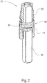
- the Fig. 2 shows a longitudinal section through such an insert body 70, which can be produced from die-cast zinc in a die-casting process, for example.
- the insert body 70 is designed as a bushing 80 which can be inserted into a corresponding recess 24 of the handle neck 23.
- the inner region of the bushing 80 forms a guide into which the driver element 30 can be inserted when the main handle part 22 is assembled.
- a recess is provided within the socket 80 in which the locking device 40 is provided.
- the locking device 40 is composed of a locking element 41 and a restoring element or a spring 42.
- the spring 42 is arranged on a stop of the bushing 80 in such a way that the spring 42 exerts a force F on the locking element 41 in the direction R2 when it is compressed.
- the locking element 41 is in turn designed as a disk-shaped element with a recess, the shape of the recess corresponding to the cross-sectional shape of the driver element 30. It is provided that the dimensions of the recess are designed so that when the driver element 30 is inserted into the recess, an air gap remains between the driver element 30 and the walls of the recess, so that a transverse play of the driver element 30 with respect to the locking element 41 remains.
- the Fig. 3 shows the insert body of the Fig. 2 without a locking element 41, driver element 30 inserted into the insert body 70 and without the spring 42 in a longitudinal section.
- the recess into which the driver element 30 can be inserted, as well as the recess (hereinafter referred to as interior 81), which is designed to accommodate the locking device 40, can again be seen clearly.
- the interior space 81 is limited in the axial direction of the insert body 70 on the one hand by the support surface 53, which is provided for mounting the spring 42.
- the interior space 81 is delimited in the opposite axial direction by an inclined surface 52 which is tilted by an angle ⁇ with respect to a plane perpendicular to the longitudinal axis L of the insert body 70.
- the direction of the tilting preferably extends along a diagonal of the cross section of the recess for the driver element 30.
- the spring 42 causes a force F on the discs of the Locking element 41, so that the locking element 41 is pressed onto the inclined surface 52.
- the angle ⁇ by which the inclined surface 52 is tilted is preferably selected such that the projection of the opening of the locking element 41 in the plane perpendicular to the longitudinal direction L of the insert body 70 is smaller in at least one direction than the cross section of the driver element 30.
- the driver element 30 exerts a force against the direction of the spring force F on the locking element 41 until the locking element 41 has been tilted so far that the driver element 30 through the opening of the locking element 41 can be passed through.
- the blocking element usually only rests on the area of the inclined surface 52 designated as the contact area 50.
- the driver element 30 If, after the driver element 30 has been inserted into the opening of the locking element 41, the driver element 30 is moved in a direction R2 opposite to the direction R1 along the direction R1, the spring 42 causes the locking element 41 to tilt about an axis that passes through the contact point of the locking element 41 is defined on the contact area 50 of the interior space 81. As a result, the locking element 41 tilts with the driver element 30, so that the driver element 30 is effectively prevented from being pulled out of the insert body 70.
- a lateral opening 54 is provided on the insert body 70. Using a suitable tool, it is thus possible to exert a force on the locking element 41 through the opening 54 against the direction of the spring force F, so that the locking element 41 is tilted so far that the locking element 41 is no longer tilted with the driver element 30.
- a Wear protection means 60 are provided.
- the wear protection means 60 can be, for example, a coating with a wear-resistant hard material, or an additional element made of a wear-resistant material such as hardened steel and attached to the corresponding surface of the insert body 70.
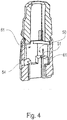
- the Fig. 4 shows a further embodiment of an insert body according to the invention with a wear protection means 60.
- an opening for example a bore 51
- a separate body 61 is mounted in the contact area 50, in which a separate body 61 is mounted.
- the position of the bore 51 and the shape and size of the separate body 61 are preferably selected such that the locking element 41 rests exclusively on the separate body 61 when the driver element 30 is inserted.
- the separate body 61 can be designed as a ball, for example, which is made of a wear-resistant material or coated with a wear-resistant material.
- an actuating handle 10 for components such as windows, doors, etc. has at least one handle 20 and a driver element 30 which can be engaged with the handle 20 in a rotationally fixed manner, with a locking device between the handle 20 and the driver element 30 40 is provided, which is designed such that the introduction of the driver element 30 into the handle 20 can be brought about in a first direction R1 and is blocked in the opposite direction R2.
- the locking device 40 has at least one locking element 41 which is acted upon by a spring force F and which can be brought into non-positive, positive and / or frictional engagement with the driver element 30, wherein the locking element 41 is designed as a locking frame that supports the driver element 30 at least in sections, and wherein the locking element 41 is pivotably mounted and is supported on a contact area 50 in the area of the handle 20.
- a wear protection means 60 is arranged or formed in the contact area 50, the blocking element 41 being supported essentially on or on the wear protection means 60 and the wear protection means 60 comprises a different material than the contact area 50.
- the wear protection means 60 consists of a wear-resistant and / or hardened material, wherein the wear protection means 60 can be a coating or a separate body 61. The latter is preferably at least partially received in a bore 51 or a recess in the contact area 50.
- the locking device 40 is designed as a preassembled structural unit in the handle 20, preferably in a handle neck 23 which has a recess 24 on the front side for receiving the locking device 40. The latter is pressed or caulked in the recess 24 in a rotationally fixed manner.
- the locking device 40 has an insert body 70, which is preferably designed as a socket 80, the locking element 41 being arranged in the socket 80 and being acted upon by the spring force F of a spring 42 which is arranged in the socket 80.
- the blocking element 41 is pressed against the wear protection means 60, which is arranged on the contact area 50, the contact area 50 being formed on the insert body 70.
- the contact area 50 is formed by an inclined surface 52 in the insert body 70, which - in a further design - is also inclined diagonally to the cross section of the driver element 30.
- the blocking element 41 rests obliquely to an axial direction A and at least at the edge on the wear protection means 50.
Landscapes
- Engineering & Computer Science (AREA)
- Mechanical Engineering (AREA)
- Lock And Its Accessories (AREA)
- Multiple-Way Valves (AREA)
- Purses, Travelling Bags, Baskets, Or Suitcases (AREA)
Priority Applications (1)
| Application Number | Priority Date | Filing Date | Title |
|---|---|---|---|
| PL17152823T PL3202999T3 (pl) | 2016-02-04 | 2017-01-24 | Uchwyt uruchamiający oraz wkładka do uchwytu uruchamiającego |
Applications Claiming Priority (1)
| Application Number | Priority Date | Filing Date | Title |
|---|---|---|---|
| DE102016102013.3A DE102016102013A1 (de) | 2016-02-04 | 2016-02-04 | Betätigungshandhabe und Einsatzkörper für eine Betätigungshandhabe |
Publications (2)
| Publication Number | Publication Date |
|---|---|
| EP3202999A1 EP3202999A1 (de) | 2017-08-09 |
| EP3202999B1 true EP3202999B1 (de) | 2020-08-26 |
Family
ID=57890692
Family Applications (1)
| Application Number | Title | Priority Date | Filing Date |
|---|---|---|---|
| EP17152823.5A Active EP3202999B1 (de) | 2016-02-04 | 2017-01-24 | Betätigungshandhabe und einsatzkörper für eine betätigungshandhabe |
Country Status (7)
| Country | Link |
|---|---|
| EP (1) | EP3202999B1 (pl) |
| CN (1) | CN107035228A (pl) |
| DE (1) | DE102016102013A1 (pl) |
| ES (1) | ES2822834T3 (pl) |
| PL (1) | PL3202999T3 (pl) |
| PT (1) | PT3202999T (pl) |
| RU (1) | RU2721044C2 (pl) |
Families Citing this family (2)
| Publication number | Priority date | Publication date | Assignee | Title |
|---|---|---|---|---|
| ES2973973T3 (es) * | 2021-01-13 | 2024-06-25 | Hoppe Ag | Manija de accionamiento para ventanas y puertas sin rosetas |
| DE102021107252A1 (de) * | 2021-03-23 | 2022-09-29 | Griffwerk GmbH | Betätigungshandhabe |
Family Cites Families (11)
| Publication number | Priority date | Publication date | Assignee | Title |
|---|---|---|---|---|
| US556587A (en) * | 1896-03-17 | Knob attachment | ||
| US1549060A (en) * | 1923-11-05 | 1925-08-11 | Edward Stephens | Doorknob |
| GB2268965B (en) * | 1992-07-24 | 1995-07-19 | Regent Lock Co Ltd | A keeper |
| DE29602822U1 (de) * | 1996-02-17 | 1996-05-15 | Bks Gmbh, 42549 Velbert | Lageranordnung mit Gleitlagerung für einen Türdrücker |
| JP4477187B2 (ja) * | 2000-03-14 | 2010-06-09 | 株式会社西製作所 | ドアハンドルの接続構造 |
| EP1683933B1 (de) | 2005-01-17 | 2012-07-25 | Hoppe Ag | Betätigungshandhabe |
| ITBS20090072A1 (it) * | 2009-04-17 | 2010-10-18 | Zamet Italia S R L | Dispositivo di interconnessione meccanica con uno stelo per maniglie di porte |
| EP2998484B1 (de) * | 2014-09-22 | 2018-12-26 | dormakaba Deutschland GmbH | Beschlag für eine gebäudetür |
| CN204492344U (zh) * | 2015-02-17 | 2015-07-22 | 刘毅 | 一种门锁执手面板 |
| CN204728814U (zh) * | 2015-05-14 | 2015-10-28 | 北京安恒利通科技股份公司 | 门把手 |
| DE202015104725U1 (de) * | 2015-09-04 | 2015-10-08 | Assa Abloy Sicherheitstechnik Gmbh | Türöffner mit Gehäusedeckel mit Schlossfallenführungsfläche |
-
2016
- 2016-02-04 DE DE102016102013.3A patent/DE102016102013A1/de not_active Ceased
-
2017
- 2017-01-24 PL PL17152823T patent/PL3202999T3/pl unknown
- 2017-01-24 ES ES17152823T patent/ES2822834T3/es active Active
- 2017-01-24 PT PT171528235T patent/PT3202999T/pt unknown
- 2017-01-24 EP EP17152823.5A patent/EP3202999B1/de active Active
- 2017-01-26 RU RU2017102470A patent/RU2721044C2/ru active
- 2017-02-03 CN CN201710063163.8A patent/CN107035228A/zh active Pending
Non-Patent Citations (1)
| Title |
|---|
| None * |
Also Published As
| Publication number | Publication date |
|---|---|
| CN107035228A (zh) | 2017-08-11 |
| ES2822834T3 (es) | 2021-05-05 |
| EP3202999A1 (de) | 2017-08-09 |
| DE102016102013A1 (de) | 2017-08-10 |
| PL3202999T3 (pl) | 2020-12-28 |
| PT3202999T (pt) | 2020-10-08 |
| RU2017102470A (ru) | 2018-07-26 |
| RU2721044C2 (ru) | 2020-05-15 |
| RU2017102470A3 (pl) | 2020-02-10 |
Similar Documents
| Publication | Publication Date | Title |
|---|---|---|
| EP3019244B1 (de) | Spreizerspitze für ein bergegerät | |
| DE102005004000A1 (de) | Mitnehmer | |
| DE10260597A1 (de) | Bremsmechanismus für eine Scheibenbremse | |
| EP3202999B1 (de) | Betätigungshandhabe und einsatzkörper für eine betätigungshandhabe | |
| DE10250960A1 (de) | Fenster-/Türgriff | |
| DE4317564A1 (de) | Türöffner mit einer verriegelbaren, schwenkbaren Falle | |
| DE202013100325U1 (de) | Drückerlagerung eines Tür- oder Fensterdrückers | |
| DE102007015199A1 (de) | Beschlag zur Verriegelung von Fenstern oder Türen | |
| DE102008058419B4 (de) | Schlosseinlauflippe mit eingelegtem Metallstreifen | |
| WO2022200421A1 (de) | Betätigungshandhabe | |
| EP1457638A1 (de) | Insektenschutzgitter mit einem Rahmen | |
| DE102022120478A1 (de) | Betätigungshandhabe | |
| DE10213024B4 (de) | Handwerkzeug und Messer zum Entgraten | |
| EP3553260B1 (de) | Falleneinsatz mit tagstellung zur bedingten freigabe einer schlossfalle eines türschlossmechanismus | |
| WO2003014500A1 (de) | Beschlag | |
| DE102016123468B3 (de) | Schnell-dreh-antriebswerkzeug | |
| EP1116838A1 (de) | Schutzbeschlag | |
| EP1757759B1 (de) | Beschlagteil für einen Treibstangenbeschlag | |
| EP2818619A1 (de) | Vorrichtung zur Regelung der Schließfolge einer zweiflügeligen Drehtüranlage | |
| DE102008064970B4 (de) | Schlosseinlauflippe mit eingeletem Metallstreifen | |
| EP1455041B1 (de) | Mehrriegelschloss mit Schubstange und mit einer Haltevorrichtung | |
| DE8913973U1 (de) | Griff-Dorn-Befestigungseinrichtung für die Betätigung eines Blattes eines Tores o.dgl. | |
| EP1818229A1 (de) | Handbremseinrichtung | |
| DE10136019C1 (de) | Handwerkzeug mit auswechselbaren Werkzeugen | |
| EP3450664B1 (de) | Verriegelungsanordnung für einen flügel |
Legal Events
| Date | Code | Title | Description |
|---|---|---|---|
| PUAI | Public reference made under article 153(3) epc to a published international application that has entered the european phase |
Free format text: ORIGINAL CODE: 0009012 |
|
| STAA | Information on the status of an ep patent application or granted ep patent |
Free format text: STATUS: THE APPLICATION HAS BEEN PUBLISHED |
|
| AK | Designated contracting states |
Kind code of ref document: A1 Designated state(s): AL AT BE BG CH CY CZ DE DK EE ES FI FR GB GR HR HU IE IS IT LI LT LU LV MC MK MT NL NO PL PT RO RS SE SI SK SM TR |
|
| AX | Request for extension of the european patent |
Extension state: BA ME |
|
| STAA | Information on the status of an ep patent application or granted ep patent |
Free format text: STATUS: REQUEST FOR EXAMINATION WAS MADE |
|
| 17P | Request for examination filed |
Effective date: 20180202 |
|
| RBV | Designated contracting states (corrected) |
Designated state(s): AL AT BE BG CH CY CZ DE DK EE ES FI FR GB GR HR HU IE IS IT LI LT LU LV MC MK MT NL NO PL PT RO RS SE SI SK SM TR |
|
| GRAP | Despatch of communication of intention to grant a patent |
Free format text: ORIGINAL CODE: EPIDOSNIGR1 |
|
| STAA | Information on the status of an ep patent application or granted ep patent |
Free format text: STATUS: GRANT OF PATENT IS INTENDED |
|
| INTG | Intention to grant announced |
Effective date: 20200323 |
|
| GRAS | Grant fee paid |
Free format text: ORIGINAL CODE: EPIDOSNIGR3 |
|
| GRAA | (expected) grant |
Free format text: ORIGINAL CODE: 0009210 |
|
| STAA | Information on the status of an ep patent application or granted ep patent |
Free format text: STATUS: THE PATENT HAS BEEN GRANTED |
|
| AK | Designated contracting states |
Kind code of ref document: B1 Designated state(s): AL AT BE BG CH CY CZ DE DK EE ES FI FR GB GR HR HU IE IS IT LI LT LU LV MC MK MT NL NO PL PT RO RS SE SI SK SM TR |
|
| REG | Reference to a national code |
Ref country code: GB Ref legal event code: FG4D Free format text: NOT ENGLISH |
|
| REG | Reference to a national code |
Ref country code: CH Ref legal event code: EP |
|
| REG | Reference to a national code |
Ref country code: DE Ref legal event code: R096 Ref document number: 502017006879 Country of ref document: DE |
|
| REG | Reference to a national code |
Ref country code: AT Ref legal event code: REF Ref document number: 1306517 Country of ref document: AT Kind code of ref document: T Effective date: 20200915 |
|
| REG | Reference to a national code |
Ref country code: IE Ref legal event code: FG4D Free format text: LANGUAGE OF EP DOCUMENT: GERMAN |
|
| REG | Reference to a national code |
Ref country code: CH Ref legal event code: NV Representative=s name: VALIPAT S.A. C/O BOVARD SA NEUCHATEL, CH |
|
| REG | Reference to a national code |
Ref country code: DK Ref legal event code: T3 Effective date: 20201002 |
|
| REG | Reference to a national code |
Ref country code: FI Ref legal event code: FGE |
|
| REG | Reference to a national code |
Ref country code: PT Ref legal event code: SC4A Ref document number: 3202999 Country of ref document: PT Date of ref document: 20201008 Kind code of ref document: T Free format text: AVAILABILITY OF NATIONAL TRANSLATION Effective date: 20201001 |
|
| REG | Reference to a national code |
Ref country code: SE Ref legal event code: TRGR |
|
| REG | Reference to a national code |
Ref country code: NL Ref legal event code: FP |
|
| REG | Reference to a national code |
Ref country code: NO Ref legal event code: T2 Effective date: 20200826 |
|
| REG | Reference to a national code |
Ref country code: GR Ref legal event code: EP Ref document number: 20200402749 Country of ref document: GR Effective date: 20201116 |
|
| REG | Reference to a national code |
Ref country code: LT Ref legal event code: MG4D |
|
| PG25 | Lapsed in a contracting state [announced via postgrant information from national office to epo] |
Ref country code: LT Free format text: LAPSE BECAUSE OF FAILURE TO SUBMIT A TRANSLATION OF THE DESCRIPTION OR TO PAY THE FEE WITHIN THE PRESCRIBED TIME-LIMIT Effective date: 20200826 Ref country code: BG Free format text: LAPSE BECAUSE OF FAILURE TO SUBMIT A TRANSLATION OF THE DESCRIPTION OR TO PAY THE FEE WITHIN THE PRESCRIBED TIME-LIMIT Effective date: 20201126 Ref country code: HR Free format text: LAPSE BECAUSE OF FAILURE TO SUBMIT A TRANSLATION OF THE DESCRIPTION OR TO PAY THE FEE WITHIN THE PRESCRIBED TIME-LIMIT Effective date: 20200826 |
|
| PG25 | Lapsed in a contracting state [announced via postgrant information from national office to epo] |
Ref country code: IS Free format text: LAPSE BECAUSE OF FAILURE TO SUBMIT A TRANSLATION OF THE DESCRIPTION OR TO PAY THE FEE WITHIN THE PRESCRIBED TIME-LIMIT Effective date: 20201226 Ref country code: LV Free format text: LAPSE BECAUSE OF FAILURE TO SUBMIT A TRANSLATION OF THE DESCRIPTION OR TO PAY THE FEE WITHIN THE PRESCRIBED TIME-LIMIT Effective date: 20200826 Ref country code: RS Free format text: LAPSE BECAUSE OF FAILURE TO SUBMIT A TRANSLATION OF THE DESCRIPTION OR TO PAY THE FEE WITHIN THE PRESCRIBED TIME-LIMIT Effective date: 20200826 |
|
| PG25 | Lapsed in a contracting state [announced via postgrant information from national office to epo] |
Ref country code: SM Free format text: LAPSE BECAUSE OF FAILURE TO SUBMIT A TRANSLATION OF THE DESCRIPTION OR TO PAY THE FEE WITHIN THE PRESCRIBED TIME-LIMIT Effective date: 20200826 Ref country code: RO Free format text: LAPSE BECAUSE OF FAILURE TO SUBMIT A TRANSLATION OF THE DESCRIPTION OR TO PAY THE FEE WITHIN THE PRESCRIBED TIME-LIMIT Effective date: 20200826 Ref country code: EE Free format text: LAPSE BECAUSE OF FAILURE TO SUBMIT A TRANSLATION OF THE DESCRIPTION OR TO PAY THE FEE WITHIN THE PRESCRIBED TIME-LIMIT Effective date: 20200826 |
|
| REG | Reference to a national code |
Ref country code: ES Ref legal event code: FG2A Ref document number: 2822834 Country of ref document: ES Kind code of ref document: T3 Effective date: 20210505 |
|
| REG | Reference to a national code |
Ref country code: DE Ref legal event code: R097 Ref document number: 502017006879 Country of ref document: DE |
|
| PG25 | Lapsed in a contracting state [announced via postgrant information from national office to epo] |
Ref country code: AL Free format text: LAPSE BECAUSE OF FAILURE TO SUBMIT A TRANSLATION OF THE DESCRIPTION OR TO PAY THE FEE WITHIN THE PRESCRIBED TIME-LIMIT Effective date: 20200826 |
|
| PG25 | Lapsed in a contracting state [announced via postgrant information from national office to epo] |
Ref country code: SK Free format text: LAPSE BECAUSE OF FAILURE TO SUBMIT A TRANSLATION OF THE DESCRIPTION OR TO PAY THE FEE WITHIN THE PRESCRIBED TIME-LIMIT Effective date: 20200826 |
|
| PLBE | No opposition filed within time limit |
Free format text: ORIGINAL CODE: 0009261 |
|
| STAA | Information on the status of an ep patent application or granted ep patent |
Free format text: STATUS: NO OPPOSITION FILED WITHIN TIME LIMIT |
|
| 26N | No opposition filed |
Effective date: 20210527 |
|
| PG25 | Lapsed in a contracting state [announced via postgrant information from national office to epo] |
Ref country code: MC Free format text: LAPSE BECAUSE OF FAILURE TO SUBMIT A TRANSLATION OF THE DESCRIPTION OR TO PAY THE FEE WITHIN THE PRESCRIBED TIME-LIMIT Effective date: 20200826 Ref country code: SI Free format text: LAPSE BECAUSE OF FAILURE TO SUBMIT A TRANSLATION OF THE DESCRIPTION OR TO PAY THE FEE WITHIN THE PRESCRIBED TIME-LIMIT Effective date: 20200826 |
|
| PG25 | Lapsed in a contracting state [announced via postgrant information from national office to epo] |
Ref country code: LU Free format text: LAPSE BECAUSE OF NON-PAYMENT OF DUE FEES Effective date: 20210124 |
|
| PG25 | Lapsed in a contracting state [announced via postgrant information from national office to epo] |
Ref country code: HU Free format text: LAPSE BECAUSE OF FAILURE TO SUBMIT A TRANSLATION OF THE DESCRIPTION OR TO PAY THE FEE WITHIN THE PRESCRIBED TIME-LIMIT; INVALID AB INITIO Effective date: 20170124 |
|
| PG25 | Lapsed in a contracting state [announced via postgrant information from national office to epo] |
Ref country code: CY Free format text: LAPSE BECAUSE OF FAILURE TO SUBMIT A TRANSLATION OF THE DESCRIPTION OR TO PAY THE FEE WITHIN THE PRESCRIBED TIME-LIMIT Effective date: 20200826 |
|
| PG25 | Lapsed in a contracting state [announced via postgrant information from national office to epo] |
Ref country code: MK Free format text: LAPSE BECAUSE OF FAILURE TO SUBMIT A TRANSLATION OF THE DESCRIPTION OR TO PAY THE FEE WITHIN THE PRESCRIBED TIME-LIMIT Effective date: 20200826 |
|
| PG25 | Lapsed in a contracting state [announced via postgrant information from national office to epo] |
Ref country code: MT Free format text: LAPSE BECAUSE OF FAILURE TO SUBMIT A TRANSLATION OF THE DESCRIPTION OR TO PAY THE FEE WITHIN THE PRESCRIBED TIME-LIMIT Effective date: 20200826 |
|
| REG | Reference to a national code |
Ref country code: CH Ref legal event code: U11 Free format text: ST27 STATUS EVENT CODE: U-0-0-U10-U11 (AS PROVIDED BY THE NATIONAL OFFICE) Effective date: 20260201 |
|
| PGFP | Annual fee paid to national office [announced via postgrant information from national office to epo] |
Ref country code: NL Payment date: 20260121 Year of fee payment: 10 |
|
| PGFP | Annual fee paid to national office [announced via postgrant information from national office to epo] |
Ref country code: SE Payment date: 20260121 Year of fee payment: 10 |
|
| PGFP | Annual fee paid to national office [announced via postgrant information from national office to epo] |
Ref country code: GB Payment date: 20260123 Year of fee payment: 10 |
|
| PGFP | Annual fee paid to national office [announced via postgrant information from national office to epo] |
Ref country code: ES Payment date: 20260227 Year of fee payment: 10 |
|
| PGFP | Annual fee paid to national office [announced via postgrant information from national office to epo] |
Ref country code: DE Payment date: 20260131 Year of fee payment: 10 Ref country code: NO Payment date: 20260123 Year of fee payment: 10 Ref country code: DK Payment date: 20260126 Year of fee payment: 10 Ref country code: IE Payment date: 20260122 Year of fee payment: 10 |
|
| PGFP | Annual fee paid to national office [announced via postgrant information from national office to epo] |
Ref country code: AT Payment date: 20260122 Year of fee payment: 10 |
|
| PGFP | Annual fee paid to national office [announced via postgrant information from national office to epo] |
Ref country code: BE Payment date: 20260121 Year of fee payment: 10 Ref country code: FI Payment date: 20260129 Year of fee payment: 10 Ref country code: IT Payment date: 20260126 Year of fee payment: 10 |
|
| PGFP | Annual fee paid to national office [announced via postgrant information from national office to epo] |
Ref country code: FR Payment date: 20260123 Year of fee payment: 10 |
|
| PGFP | Annual fee paid to national office [announced via postgrant information from national office to epo] |
Ref country code: TR Payment date: 20260120 Year of fee payment: 10 |
|
| PGFP | Annual fee paid to national office [announced via postgrant information from national office to epo] |
Ref country code: PT Payment date: 20260120 Year of fee payment: 10 Ref country code: CZ Payment date: 20260121 Year of fee payment: 10 Ref country code: CH Payment date: 20260201 Year of fee payment: 10 |
|
| PGFP | Annual fee paid to national office [announced via postgrant information from national office to epo] |
Ref country code: GR Payment date: 20260122 Year of fee payment: 10 Ref country code: PL Payment date: 20260121 Year of fee payment: 10 |