EP3202484A1 - Inline-diafiltrierung mit mehrkanaliger pumpe - Google Patents
Inline-diafiltrierung mit mehrkanaliger pumpe Download PDFInfo
- Publication number
- EP3202484A1 EP3202484A1 EP17151017.5A EP17151017A EP3202484A1 EP 3202484 A1 EP3202484 A1 EP 3202484A1 EP 17151017 A EP17151017 A EP 17151017A EP 3202484 A1 EP3202484 A1 EP 3202484A1
- Authority
- EP
- European Patent Office
- Prior art keywords
- fluid
- diafiltration
- feed
- permeate
- separate
- Prior art date
- Legal status (The legal status is an assumption and is not a legal conclusion. Google has not performed a legal analysis and makes no representation as to the accuracy of the status listed.)
- Granted
Links
Images


Classifications
-
- B—PERFORMING OPERATIONS; TRANSPORTING
- B01—PHYSICAL OR CHEMICAL PROCESSES OR APPARATUS IN GENERAL
- B01D—SEPARATION
- B01D61/00—Processes of separation using semi-permeable membranes, e.g. dialysis, osmosis or ultrafiltration; Apparatus, accessories or auxiliary operations specially adapted therefor
- B01D61/02—Reverse osmosis; Hyperfiltration ; Nanofiltration
- B01D61/025—Reverse osmosis; Hyperfiltration
- B01D61/026—Reverse osmosis; Hyperfiltration comprising multiple reverse osmosis steps
-
- A—HUMAN NECESSITIES
- A61—MEDICAL OR VETERINARY SCIENCE; HYGIENE
- A61M—DEVICES FOR INTRODUCING MEDIA INTO, OR ONTO, THE BODY; DEVICES FOR TRANSDUCING BODY MEDIA OR FOR TAKING MEDIA FROM THE BODY; DEVICES FOR PRODUCING OR ENDING SLEEP OR STUPOR
- A61M1/00—Suction or pumping devices for medical purposes; Devices for carrying-off, for treatment of, or for carrying-over, body-liquids; Drainage systems
- A61M1/34—Filtering material out of the blood by passing it through a membrane, i.e. hemofiltration or diafiltration
- A61M1/3413—Diafiltration
-
- B—PERFORMING OPERATIONS; TRANSPORTING
- B01—PHYSICAL OR CHEMICAL PROCESSES OR APPARATUS IN GENERAL
- B01D—SEPARATION
- B01D61/00—Processes of separation using semi-permeable membranes, e.g. dialysis, osmosis or ultrafiltration; Apparatus, accessories or auxiliary operations specially adapted therefor
- B01D61/02—Reverse osmosis; Hyperfiltration ; Nanofiltration
- B01D61/08—Apparatus therefor
-
- B—PERFORMING OPERATIONS; TRANSPORTING
- B01—PHYSICAL OR CHEMICAL PROCESSES OR APPARATUS IN GENERAL
- B01D—SEPARATION
- B01D61/00—Processes of separation using semi-permeable membranes, e.g. dialysis, osmosis or ultrafiltration; Apparatus, accessories or auxiliary operations specially adapted therefor
- B01D61/02—Reverse osmosis; Hyperfiltration ; Nanofiltration
- B01D61/12—Controlling or regulating
-
- B—PERFORMING OPERATIONS; TRANSPORTING
- B01—PHYSICAL OR CHEMICAL PROCESSES OR APPARATUS IN GENERAL
- B01D—SEPARATION
- B01D61/00—Processes of separation using semi-permeable membranes, e.g. dialysis, osmosis or ultrafiltration; Apparatus, accessories or auxiliary operations specially adapted therefor
- B01D61/14—Ultrafiltration; Microfiltration
-
- B—PERFORMING OPERATIONS; TRANSPORTING
- B01—PHYSICAL OR CHEMICAL PROCESSES OR APPARATUS IN GENERAL
- B01D—SEPARATION
- B01D61/00—Processes of separation using semi-permeable membranes, e.g. dialysis, osmosis or ultrafiltration; Apparatus, accessories or auxiliary operations specially adapted therefor
- B01D61/14—Ultrafiltration; Microfiltration
- B01D61/145—Ultrafiltration
-
- B—PERFORMING OPERATIONS; TRANSPORTING
- B01—PHYSICAL OR CHEMICAL PROCESSES OR APPARATUS IN GENERAL
- B01D—SEPARATION
- B01D61/00—Processes of separation using semi-permeable membranes, e.g. dialysis, osmosis or ultrafiltration; Apparatus, accessories or auxiliary operations specially adapted therefor
- B01D61/14—Ultrafiltration; Microfiltration
- B01D61/18—Apparatus therefor
-
- B—PERFORMING OPERATIONS; TRANSPORTING
- B01—PHYSICAL OR CHEMICAL PROCESSES OR APPARATUS IN GENERAL
- B01D—SEPARATION
- B01D61/00—Processes of separation using semi-permeable membranes, e.g. dialysis, osmosis or ultrafiltration; Apparatus, accessories or auxiliary operations specially adapted therefor
- B01D61/14—Ultrafiltration; Microfiltration
- B01D61/22—Controlling or regulating
-
- B—PERFORMING OPERATIONS; TRANSPORTING
- B01—PHYSICAL OR CHEMICAL PROCESSES OR APPARATUS IN GENERAL
- B01D—SEPARATION
- B01D63/00—Apparatus in general for separation processes using semi-permeable membranes
- B01D63/08—Flat membrane modules
-
- B—PERFORMING OPERATIONS; TRANSPORTING
- B01—PHYSICAL OR CHEMICAL PROCESSES OR APPARATUS IN GENERAL
- B01D—SEPARATION
- B01D63/00—Apparatus in general for separation processes using semi-permeable membranes
- B01D63/08—Flat membrane modules
- B01D63/082—Flat membrane modules comprising a stack of flat membranes
- B01D63/084—Flat membrane modules comprising a stack of flat membranes at least one flow duct intersecting the membranes
- B01D63/085—Flat membrane modules comprising a stack of flat membranes at least one flow duct intersecting the membranes specially adapted for two fluids in mass exchange flow
-
- C—CHEMISTRY; METALLURGY
- C07—ORGANIC CHEMISTRY
- C07K—PEPTIDES
- C07K1/00—General methods for the preparation of peptides, i.e. processes for the organic chemical preparation of peptides or proteins of any length
- C07K1/14—Extraction; Separation; Purification
- C07K1/34—Extraction; Separation; Purification by filtration, ultrafiltration or reverse osmosis
-
- C—CHEMISTRY; METALLURGY
- C07—ORGANIC CHEMISTRY
- C07K—PEPTIDES
- C07K16/00—Immunoglobulins [IG], e.g. monoclonal or polyclonal antibodies
-
- C—CHEMISTRY; METALLURGY
- C12—BIOCHEMISTRY; BEER; SPIRITS; WINE; VINEGAR; MICROBIOLOGY; ENZYMOLOGY; MUTATION OR GENETIC ENGINEERING
- C12N—MICROORGANISMS OR ENZYMES; COMPOSITIONS THEREOF; PROPAGATING, PRESERVING, OR MAINTAINING MICROORGANISMS; MUTATION OR GENETIC ENGINEERING; CULTURE MEDIA
- C12N15/00—Mutation or genetic engineering; DNA or RNA concerning genetic engineering, vectors, e.g. plasmids, or their isolation, preparation or purification; Use of hosts therefor
- C12N15/09—Recombinant DNA-technology
- C12N15/10—Processes for the isolation, preparation or purification of DNA or RNA
- C12N15/1003—Extracting or separating nucleic acids from biological samples, e.g. pure separation or isolation methods; Conditions, buffers or apparatuses therefor
- C12N15/1017—Extracting or separating nucleic acids from biological samples, e.g. pure separation or isolation methods; Conditions, buffers or apparatuses therefor by filtration, e.g. using filters, frits, membranes
-
- B—PERFORMING OPERATIONS; TRANSPORTING
- B01—PHYSICAL OR CHEMICAL PROCESSES OR APPARATUS IN GENERAL
- B01D—SEPARATION
- B01D2311/00—Details relating to membrane separation process operations and control
- B01D2311/04—Specific process operations in the feed stream; Feed pretreatment
-
- B—PERFORMING OPERATIONS; TRANSPORTING
- B01—PHYSICAL OR CHEMICAL PROCESSES OR APPARATUS IN GENERAL
- B01D—SEPARATION
- B01D2311/00—Details relating to membrane separation process operations and control
- B01D2311/06—Specific process operations in the permeate stream
-
- B—PERFORMING OPERATIONS; TRANSPORTING
- B01—PHYSICAL OR CHEMICAL PROCESSES OR APPARATUS IN GENERAL
- B01D—SEPARATION
- B01D2311/00—Details relating to membrane separation process operations and control
- B01D2311/14—Pressure control
-
- B—PERFORMING OPERATIONS; TRANSPORTING
- B01—PHYSICAL OR CHEMICAL PROCESSES OR APPARATUS IN GENERAL
- B01D—SEPARATION
- B01D2311/00—Details relating to membrane separation process operations and control
- B01D2311/16—Flow or flux control
-
- B—PERFORMING OPERATIONS; TRANSPORTING
- B01—PHYSICAL OR CHEMICAL PROCESSES OR APPARATUS IN GENERAL
- B01D—SEPARATION
- B01D2311/00—Details relating to membrane separation process operations and control
- B01D2311/16—Flow or flux control
- B01D2311/165—Cross-flow velocity control
-
- B—PERFORMING OPERATIONS; TRANSPORTING
- B01—PHYSICAL OR CHEMICAL PROCESSES OR APPARATUS IN GENERAL
- B01D—SEPARATION
- B01D2313/00—Details relating to membrane modules or apparatus
- B01D2313/18—Specific valves
-
- B—PERFORMING OPERATIONS; TRANSPORTING
- B01—PHYSICAL OR CHEMICAL PROCESSES OR APPARATUS IN GENERAL
- B01D—SEPARATION
- B01D2313/00—Details relating to membrane modules or apparatus
- B01D2313/24—Specific pressurizing or depressurizing means
- B01D2313/243—Pumps
-
- B—PERFORMING OPERATIONS; TRANSPORTING
- B01—PHYSICAL OR CHEMICAL PROCESSES OR APPARATUS IN GENERAL
- B01D—SEPARATION
- B01D2313/00—Details relating to membrane modules or apparatus
- B01D2313/54—Modularity of membrane module elements
-
- B—PERFORMING OPERATIONS; TRANSPORTING
- B01—PHYSICAL OR CHEMICAL PROCESSES OR APPARATUS IN GENERAL
- B01D—SEPARATION
- B01D2315/00—Details relating to the membrane module operation
- B01D2315/10—Cross-flow filtration
-
- B—PERFORMING OPERATIONS; TRANSPORTING
- B01—PHYSICAL OR CHEMICAL PROCESSES OR APPARATUS IN GENERAL
- B01D—SEPARATION
- B01D2315/00—Details relating to the membrane module operation
- B01D2315/12—Feed-and-bleed systems
-
- B—PERFORMING OPERATIONS; TRANSPORTING
- B01—PHYSICAL OR CHEMICAL PROCESSES OR APPARATUS IN GENERAL
- B01D—SEPARATION
- B01D2315/00—Details relating to the membrane module operation
- B01D2315/16—Diafiltration
-
- B—PERFORMING OPERATIONS; TRANSPORTING
- B01—PHYSICAL OR CHEMICAL PROCESSES OR APPARATUS IN GENERAL
- B01D—SEPARATION
- B01D2319/00—Membrane assemblies within one housing
- B01D2319/04—Elements in parallel
Definitions
- Diafiltration is a technique that uses ultrafiltration (UF) membranes to remove, replace, or lower the concentration of undesirable materials such as salts and/or solvents from fluids containing desirable materials, for example, desired biomolecules such as proteins, peptides, and nucleic acids.
- UF membrane retains molecules that are larger than the pores of the membrane (the solution containing the retained molecules is referred to as the retentate or concentrate), and smaller molecules such as salts, solvents, and water (which are 100% permeable), freely pass through the membrane (providing a solution referred to as the permeate or filtrate).
- Continuous diafiltration involves washing out the original buffer salts (and/or other low molecular weight species) in the retentate by adding water or new buffer to the retentate at the same rate as filtrate is being generated.
- the retentate volume and product concentration does not change during the diafiltration process. If water is used for diafiltering, the salts will be washed out and the conductivity lowered. If a buffer is used for diafiltering, the new buffer salt concentration will increase at a rate inversely proportional to that of the species being removed, and the conductivity will be increased. The amount of salt removed is related to the filtrate volume generated, relative to the retentate volume.
- the filtrate volume generated is usually referred to in terms of "diafiltration volumes.”
- a single diafiltration volume (DV) is the volume of retentate when diafiltration is started.
- liquid is added at the same rate as filtrate is generated.
- the volume of filtrate collected equals the starting retentate volume, 1 DV has been processed.
- greater than 99.5% of a 100% permeable solute can be removed by washing through 6 retentate volumes (6DV) with the buffer of choice.
- the present invention provides for ameliorating at least some of the disadvantages of the prior art.
- An embodiment of the invention provides a diafiltration system comprising (a) a fluid treatment assembly comprising two or more fluid treatment modules, the fluid treatment assembly comprising a feed inlet, and permeate outlet, and a retentate outlet; (i) each fluid treatment module comprising a cross flow treatment assembly including at least one ultrafiltration membrane, the fluid treatment assembly comprising having at least one feed side and at least one opposite permeate side, and a diafiltration fluid distribution plate comprising a diafiltration fluid feed inlet and a common feed permeate/diafiltration fluid permeate outlet port; (b) two or more separate diafiltration fluid conduits, each separate diafiltration fluid conduit in fluid communication with a respective single diafiltration fluid feed inlet; and, (c) a diafiltration fluid pump, the diafiltration fluid pump comprising at least a first multiple channel pump head having at least two channels including separate channels for separate diafiltration fluid conduits in fluid communication with respective single diafiltration fluid feed inlets, wherein the diafiltration pump provides simultaneously controlled diafiltration fluid
- a method of diafiltration comprising passing a feed fluid containing undesirable material and desirable biomolecules, and a diafiltration fluid suitable for washing out undesirable material from the feed fluid, through the fluid treatment assembly in an embodiment of the diafiltration system, wherein the method includes (a) passing the feed fluid at a controlled feed fluid flow rate through the feed inlet of the fluid treatment assembly; (b) passing the diafiltration fluid at a controlled diafiltration fluid flow rate through each of the separate diafiltration fluid conduits in fluid communication with respective single diafiltration fluid feed inlets, such that the diafiltration fluid washes undesirable material from the feed fluid, wherein the controlled diafiltration fluid flow rate is simultaneously controlled through each of the separate diafiltration fluid conduits; (c) passing a feed permeate/diafiltration fluid permeate fluid through each of the common feed permeate/diafiltration fluid permeate outlet ports; (d) passing a retentate fluid from the retentate outlet of fluid treatment assembly, the retentate fluid comprising
- a diafiltration system comprising (a) a fluid treatment assembly comprising two or more fluid treatment modules, the fluid treatment assembly comprising a feed inlet, and permeate outlet, and a retentate outlet; (i) each fluid treatment module comprising a cross flow treatment assembly including at least one ultrafiltration membrane, the cross flow treatment assembly having at least one feed side and at least one opposite permeate side, and a diafiltration fluid distribution plate comprising a diafiltration fluid feed inlet and a common feed permeate/diafiltration fluid permeate outlet port; (b) two or more separate diafiltration fluid conduits, each separate diafiltration fluid conduit in fluid communication with a respective single diafiltration fluid feed inlet; and, (c) a diafiltration fluid pump, the diafiltration fluid pump comprising at least a first multiple channel pump head having at least two channels including separate channels for separate diafiltration fluid conduits in fluid communication with respective single diafiltration fluid feed inlets, wherein the diafiltration
- a diafiltration fluid distribution plate comprising a diafiltration fluid feed inlet and the diafiltration fluid feed channel communicating with the diafiltration fluid feed inlet, and a common feed retentate port, wherein the common feed retentate port has 2 different inner diameters.
- the diafiltration system further comprises a feed fluid pump and a feed fluid conduit, wherein the feed fluid conduit is in fluid communication with the fluid treatment assembly feed inlet, wherein the feed fluid pump provides a controlled feed fluid flow rate through the feed fluid conduit to the fluid treatment assembly feed inlet.
- the diafiltration system includes at least one additional channel pump head having including a separate channel for a separate diafiltration fluid conduit in fluid communication with a single diafiltration fluid feed inlet, wherein the pump, via the first multiple channel pump head and the additional channel pump head, provides simultaneously controlled diafiltration fluid flow rates through each of the separate diafiltration fluid conduits to the respective single diafiltration fluid feed inlets.
- an embodiment of the diafiltration system of claim includes at least one additional multiple channel pump head having at least two channels including a separate channel for a separate diafiltration fluid conduit in fluid communication with a single diafiltration fluid feed inlet, wherein the pump, via the first multiple channel pump head and the additional multiple channel pump head, provides simultaneously controlled diafiltration fluid flow rates through each of the separate diafiltration fluid conduits to the respective single diafiltration fluid feed inlets.
- the diafiltration system further comprises a retentate throttling valve, arranged to allow the system to maintain a desired ratio of feed flow rate to retentate flow rate.
- a method of diafiltration comprising passing a feed fluid containing undesirable material and desirable biomolecules, and a diafiltration fluid suitable for washing out undesirable material from the feed fluid, through the fluid treatment assembly in an embodiment of the diafiltration system, wherein the method includes (a) passing the feed fluid at a controlled feed fluid flow rate through the feed inlet of the fluid treatment assembly; (b) passing the diafiltration fluid at a controlled diafiltration fluid flow rate through each of the separate diafiltration fluid conduits in fluid communication with respective single diafiltration fluid feed inlets, such that the diafiltration fluid washes undesirable material from the feed fluid, wherein the controlled diafiltration fluid flow rate is simultaneously controlled through each of the separate diafiltration fluid conduits; (c) passing a feed permeate/diafiltration fluid permeate fluid through each of the common feed permeate/diafiltration fluid permeate outlet ports; (d) passing a retentate fluid from the retentate outlet of fluid treatment assembly, the retentate fluid comprising
- the feed fluid pump provides a controlled feed fluid flow rate through the feed fluid conduit to the fluid treatment assembly feed inlet at a flow rate that is lower than (e.g., at least about 10% lower than) the simultaneously controlled diafiltration fluid flow rates through each of the separate diafiltration fluid conduits provided by the diafiltration pump.
- the invention is suitable for discontinuous diafiltration (including sequential dilution and volume reduction), and, more preferably, continuous diafiltration, wherein the diafiltration fluid flow rate is managed through a single point of control.
- continuous diafiltration as conventionally carried out involves the continuous addition of buffer to into the product tank, and the product of interest (e.g., desirable proteins) is recirculated within the system
- embodiments of the invention can encompass "continuous diafiltration in its entirety," such that the product of interest is not recirculated within the system; rather, it is processed continuously in a single-pass mode of operation.
- Fluids can be passed through the fluid treatment assembly in co-current and counter-current flow directions, in a single-pass mode or a continuous-pass mode.
- Fluid treatment assemblies can include any number of fluid treatment modules (e.g., "stages,” such as 2, 3, 4, 5, 6, 7, or more, stages), wherein an individual module (stage) includes one or more cross fluid treatment assemblies).
- Fluid treatment assemblies (including feed and/or permeate channels) can be arranged in any flow configuration (serial flow and/or parallel flow) to provide a fluid path of desired length (e.g., 1-in-series, 2-in-series, etc.). In-line diafiltration is preferred.
- Advantages include one or more of any of the following: a reduced footprint, a reduced number of moving parts, improved process integration including simplified operational requirements, reduced working volume, and reduced hold up volume.
- a variety of desired removal efficiencies can be obtained, e.g., about 99% (2 log), about 99.9% (3 log) and about 99.99% (4 log), or even higher. However, for some applications, lower buffer efficiencies are suitable.
- the feed fluid pump provides a controlled feed fluid flow rate through the feed fluid conduit to the fluid treatment assembly feed inlet at a flow rate that is lower than the simultaneously controlled diafiltration fluid flow rates through each of the separate diafiltration fluid conduits provided by the diafiltration pump (i.e., the diafiltration fluid rate rate through each channel is higher than the feed fluid flow rate).
- the controlled diafiltration fluid flow rates through each of the separate diafiltration fluid conduits is at least about 13% higher, providing a 2 log removal efficiency; at least about 50% higher, providing a 3 log removal efficiency; and at least about 70% higher, providing a 4 log removal efficiency.
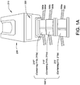
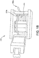
- Fig. 1A shows an illustrative embodiment of a diafiltration system 1000, comprising a diafiltration pump 200 including a driver 210 (preferably microprocessor controlled), multiple channel pump heads 215' (including separate channels 215 and 215a), 215" (including separate channels 215b and 215c), and 215"' (including separate channels 215d and 215e) (215' with separate channels 215, 215a, shown in more detail in Fig. 1B ), wherein the channels are suitable for receiving conduits such as diafiltration fluid conduits, wherein the system also includes a fluid treatment assembly 500.
- the diafiltration pump also includes a display 220.
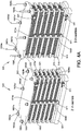
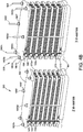
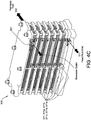
- the illustrative fluid treatment assembly 500 shown in Figures 2A-2D , and 4A-4C comprises a bottom support plate 501, a top support plate 502, a bottom manifold plate 510 (e.g., a feed bottom manifold plate), and a top manifold plate 520 (e.g., a retentate/permeate top manifold plate), wherein the bottom and top manifold plates include one or more ports, such as a feed inlet 511, a retentate outlet 521, and a permeate outlet 522.
- the bottom manifold plate 510 comprises the feed inlet 511 (for introducing feed solution into the filter assembly), and the top manifold plate comprises the retentate outlet 521 (which allows buffer exchanged feed (e.g., protein) solution to pass to a collection vessel) and the permeate outlet 522 (which discharges exchange buffer).
- the feed inlet 511 for introducing feed solution into the filter assembly
- the top manifold plate comprises the retentate outlet 521 (which allows buffer exchanged feed (e.g., protein) solution to pass to a collection vessel) and the permeate outlet 522 (which discharges exchange buffer).
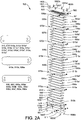
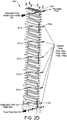
- the fluid treatment assembly 500 includes two or more fluid treatment modules 530, (530a, 530b, 530c, 530d, 530e). While a fluid treatment module can include a single cross flow treatment assembly, typically, and as illustrated in Figure 2A for example, an individual treatment module includes a plurality of cross flow treatment assemblies (550, 550', 550a, 550a', 550b, 550b', 550c, 550c', 550d, 550d', 550e, 550e'), each including at least one ultrafiltration membrane (membranes are shown in Figure 2B , illustrating membranes 560, 560', 560" and 560"' in a single cross flow treatment assembly), the cross flow treatment assembly having at least one feed side (sometimes referred to as a feed channel or feed layer) (illustratively shown in Figure 2B , showing feed channels 561, 561'), and at least one opposite permeate side (sometimes referred to as a perme
- the diafiltration plate can include a common feed permeate/diafiltration fluid permeate outlet channel 744 (744a, 744b, 744c, 744d, 744e) and a common feed permeate/diafiltration fluid permeate aperture 745 (745a, 745b, 745c, 745d, 745e) in fluid communication with the common feed permeate/diafiltration fluid permeate outlet port.
- some or all of the apertures are capped, preventing fluid flow therethrough (such that fluid flows through the common feed permeate/diafiltration fluid permeate outlet port 700, but not the common feed permeate/diafiltration fluid permeate outlet channel 744 or the common feed permeate/diafiltration fluid permeate aperture 745).
- Figures 3A and 3B also various configurations for the common feed/retentate port and the diafiltration fluid feed channel in the diafiltration plate, for introducing the diafiltration fluid into the feed/retentate port at different angles.
- the "teardrop shaped" port 600 has 2 different inner diameters (601 having a larger opening coming to a point 603 at one surface of the plate, the opening being larger than the opening 602 in the round port below, such that there is a lip or shoulder 604 between the teardrop shape and the round aperture) may provide improved results, e.g., by providing a larger surface area for the mixing of feed and diafiltration (buffer) fluid streams.
- the fluid treatment assembly includes at least one, more preferably, at least two, gaskets, wherein at least one gasket has 3 apertures and at least one gasket has 2 apertures.
- Figure 2A illustrates gasket 510a between the first stage 530 and lower manifold plate 510, gasket 520b between sixth stage 530e and the upper manifold plate 520, and gasket 510b between diafiltration plate 570 and cross treatment assembly 550, wherein each gasket has 2 apertures
- Figure 2A also illustrates gaskets 515 (515', 515a, 515a', 515a", 515b, 515b', 515b", 515c, 515c', 515c", 515d, 515d', 515d", 515e, 515e') each having 3 apertures, on either side of the cross flow assemblies, with the exception of the first and last cross flow assemblies (wherein gaskets 510b and 520a are on one side of the cross flow treatment assemblies).
- the illustrated system 1000 includes a plurality of separate diafiltration fluid feed conduits 590' (590, 590a, 590b, 590c, 590d, 590e), in fluid communication with a diafiltration fluid (e.g., buffer fluid) source 1570, and diafiltration fluid feed inlets, wherein the diafiltration fluid feed conduits are separately arranged in the separate channels of the multiple channel pump head(s).
- a diafiltration fluid e.g., buffer fluid
- the fluid treatment assembly can be assembled as is known in the art. In the illustrated assembly shown in Figs. 4A and 4B , the modules are stacked. If desired, the fluid treatment assemblies can include, for example, rods (e.g., compression and/or mounting rods), bolts, nuts, and washers, including, for example, as disclosed in U.S. Patent 7,918,999 , and U.S. Patent Application Publications 2008/0135499 and 2013/0118971 .
- rods e.g., compression and/or mounting rods
- bolts e.g., nuts, and washers
- the fluid treatment assemblies include threaded compression rods 1800 (1800a, 1800b, 1800c), threaded mounting rods 1800', 1800a' (wherein the mounting rods only pass through the support plates, and the compression rods pass through the support plates, the manifold plates and the diafiltration plates), washers 1801 (1801a, 1801b, 1801 c; 1801', 1800a') and threaded nuts 1802 (1802a, 1802b, 1802c; 1802', 1802a'), wherein the top and bottom support plates, the top and bottom manifold plates, and the diafiltration distribution plates, include holes allowing the rods to pass therethrough such that the modules can be stacked.
- the mounting rods provide alignment support during stacking and assembling the modules, and the compression rods ensure application of a desired load and torque to functionalize the fluid treatment assembly.
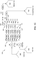
- the system 1000 further comprises a feed fluid pump 1500, a feed fluid source 1510, and at least one feed fluid conduit, 1511, in fluid communication with the feed inlet 511, at least one retentate conduit 1521 in fluid communication with the retentate outlet 521 and a collection container 1621, at least one permeate conduit 1522 in fluid communication with the permeate outlet 522 and a permeate/waste container 1622, typically, wherein the permeate conduit 1522 is also in fluid communication with one or more common feed permeate/diafiltration fluid permeate outlet ports (e.g., Figure 2D shows permeate passing through each of the common permeate ports (700, 700a, 700b, 700c, 700d, 700e) through permeate outlet 522 to permeate conduit 1522).
- Figure 2D shows permeate passing through each of the common permeate ports (700, 700a, 700b, 700c, 700d, 700e) through permeate outlet 522 to permeate conduit 1522).
- the system can include one or more diafiltration fluid permeate conduits in fluid communication with the common feed permeate/diafiltration fluid permeate outlet channels 744 (744, 744a, 744b) and the common feed permeate/diafiltration fluid permeate apertures (745, 745a, 745b (the apertures shown as capped in Figure 2D )) and the permeate/waste container 1622 and/or a diafiltration permeate container (conduits and diafiltration permeate container not shown).
- the system can also include, for example, one or more monitoring devices for monitoring one or more of any of the following: pressure (e.g., inlet pressure, outlet pressure and/or backpressure), flow rates, and conductivity, and/or one or more valves, e.g., retentate and/or permeate throttling valves (sometimes referred to as control valves), for example, for adjusting one or more of any of the following: flow ratio between feed and retentate, and/or adjusting backpressure.
- pressure e.g., inlet pressure, outlet pressure and/or backpressure
- valves e.g., retentate and/or permeate throttling valves (sometimes referred to as control valves)
- retentate and/or permeate throttling valves sometimes referred to as control valves
- Suitable flow meters, pressure sensors, conductivity sensors, and throttle valves are known in the art.
- the system comprises flow meters and pressure sensors associated with each inlet fluid flow path communicating with the fluid treatment assembly, and with the retentate fluid path path exiting the fluid treatment assembly, and conductivity sensors and throttle valves associated with the retentate and permeate fluid flow paths exiting the fluid treatment assembly.
- a flow meter and a pressure sensor are associated with the feed fluid inlet fluid flow path
- a flow meter and a pressure sensor is associated with the retentate fluid flow path.
- the embodiment of the system illustrated in Fig. 1C comprises a flow meter 800' and 900' associated with feed conduit 1511, as well as flow meters 800 (800a, 800b, 800c, 800d, 800e) and pressure sensors 900 (900a, 900b, 900c, 900d, 900e) associated with the respective diafiltration feed fluid conduits 590 (590, 590a, 590b, 590c, 590d, 590e), also comprising flow meter 821 and pressure sensor 921 associated with retentate conduit 1521, as well as conductivity sensor 1021 and throttle valve 1121 associated with retentate conduit 1521, and conductivity sensor 1022 and throttle valve 1122 associated with permeate conduit 1522.
- the throttle valve 1122 is replaced with a flow meter, and the system does not include flow meters and pressure sensors associated with the respective diafiltration feed fluid conduits.
- a variety of diafiltration fluid and feed fluid pumps preferably microprocessor controlled drive pumps
- multiple channel (e.g., 2, 4, 8, 12, 16, and 24 channel, or more channels) pump heads are suitable for use in the invention, and suitable pumps and pump heads are commercially available (e.g., from Cole-Palmer Instrument Company (Vernon Hills, IL), under the names MASTERFLEX, and ISMATEC, among others).
- the pumps have multiple rollers, e.g., 2, 3, 4, or more rollers).
- the diafiltration pump (and for some applications, the feed pump) provides a calibrated flow rate, and, if desired, a calibrated dispensing volume.
- the multiple channel pump head is integral with the pump.
- a multiple channel head can be used, along with additional pump heads that can be multiple channel and/or single channel.
- Embodiments of the invention can utilize a variety of tubing sizes and/or tubing materials, and suitable sizes and materials are known to one of skill in the art.
- the diafiltration distribution plate can be formed of various materials known in the art, including, for example, polymeric materials such as polypropylene.
- feed channels and permeate channels are suitable for use in the invention.
- the feed channels and permeate channels include spacer materials and/or perforate materials such as screens or meshes.
- the screens or meshes can have any suitable size openings, e.g., fine, medium, or coarse size openings.
- a cross fluid treatment assembly can have any number of membranes, feed channels, and permeate channels, including, for example, those disclosed in U.S. Patent 8,980,088 .
- Figure 2B illustrates an exemplary cross fluid treatment assembly 550 comprising 4 UF membranes (560, 560', 560", 560"'), wherein each membrane is arranged between a permeate channel (562, 562', 562") and a feed channel (561, 561').
- cross fluid treatment assembly components can be combined to provide cross fluid treatment sub-assemblies, e.g., wherein a permeate channel and a membrane are combined to form a permeate channel/membrane sub-assembly.
- Figure 2C shows top, middle, and bottom permeate channel/membrane sub-assemblies 550-1, 550-2, and 550-3, respectively, and a feed channel is arranged between the top and middle sub-assembly, and another feed channel is arranged between the middle sub-assembly and the bottom sub-assembly.
- Figure 2C shows various seals associated with various cross fluid treatment components, illustrated as feed channel seals 561a', 561a", 561'a', 561'a", and permeate channel seals 562a', 562a".
- the UF membrane can be formed from any of numerous materials, including those known in the art, including, for example, a natural or synthetic polymer, including, e.g., regenerated cellulose, polyethersulfone, etc.
- the membrane can be supported or unsupported.
- the membrane can have any suitable pore structure, e.g., a wide range of molecular cutoffs (such as, e.g., 10 kDa, 30 kDa, etc.) or removal ratings. Suitable membranes include those known in the art.
- the membrane may have, or may be modified to have, any of a myriad of fluid treatment characteristics.
- the membrane may have a positive, negative, or neutral electrical charge; it may be liquiphobic or liquiphilic, including hydrophobic or hydrophilic or oleophobic or oleophilic; and/or it may have attached functional groups, such as ligands or any other reactive moiety, that can chemically bind to substances in the fluid.
- the membrane may be formed from, impregnated with, or otherwise contain a variety of materials that function to further treat the fluid in any of numerous ways.
- These functional materials may include, for example, sorbents, ion exchange resins, chromatography media, enzymes, reactants, or catalysts of all types that may chemically and/or physically bind, react with, catalyze, deliver, or otherwise affect substances in the fluid or the fluid itself.
- the membrane can have any desired critical wetting surface tension (CWST, as defined in, for example, U.S. Patent 4,925,572 ).
- CWST can be selected as is known in the art, e.g., as additionally disclosed in, for example, U.S. Patents 5,152,905 , 5,443,743 , 5,472,621 , and 6,074,869 .
- a diafiltration system is set up including a fluid treatment assembly as generally shown in Fig. 4 (A and B), wherein the diafiltration pump and diafiltration system are arranged as generally shown in Figs. 1A and 1C , including a MASTERFLEX L/S Precision Variable Speed Pump Drive (Model No: EW-07528-30), with three MASTERFLEX L/S Multi-channel Pump Heads (Model No: 07536-002) and MASTERFLEX L/S High Performance Precision 2-stop tubing sets (L/S 15, 06421-15) (Cole-Palmer Instrument Company, Vernon Hills, IL).
- MASTERFLEX L/S Precision Variable Speed Pump Drive Model No: EW-07528-30
- MASTERFLEX L/S Multi-channel Pump Heads Model No: 07536-002
- MASTERFLEX L/S High Performance Precision 2-stop tubing sets L/S 15, 06421-15
- the fluid treatment assembly has 6 stages, each stage having 2-in-series cross fluid treatment assemblies, each cross fluid treatment assembly including Delta regenerated cellulose UF membranes, each with a 30 kDa cutoff and a surface area of 186 cm 2 (total membrane area for the fluid treatment assembly is 2232 cm 2 ).
- the feed solution is 10 g/L polyclonal bovine IgG in 0.025 M sodium acetate plus 0.5 M sodium chloride (NaCl) (conductivity 47 mS/cm).
- the diafiltration (DF) solution (buffer solution) is 0.025 M sodium acetate plus 0.05 M NaCl (conductivity 6.7 mS/cm).
- the diafiltration fluid flow rate in each channel is about 11.7 mL/min, and when the feed fluid flow rate is 20 mL/min, the diafiltration fluid flow rate in each channel is about 23.3 mL/min.
- the diafiltration system, fluid treatment assembly, and feed and DF solutions are as described in Example 1.
- the diafiltration fluid flow rate in each channel is about 10.8 mL/min, and when the feed fluid flow rate is 10 mL/min, the diafiltration fluid flow rate in each channel is about 22.7 mL/min.
- both the pressure and flow rate management is relatively easy and uniform for targeting the 99.9% removal efficiency.
- the diafiltration system, fluid treatment assembly, and feed and DF solutions are as described in Example 1.
- a diafiltration system is set up including a fluid treatment assembly as generally described in Example 1.
- the fluid treatment assembly has 6 stages, each stage having 3-in-series cross fluid treatment assemblies, each cross fluid treatment assembly including Delta regenerated cellulose UF membranes, each with a 30 kDa cutoff and a surface area of 186 cm 2 .
- the feed solution is 60 g/L polyclonal bovine IgG in 0.025 M sodium acetate plus 0.5 M sodium chloride (NaCl) (conductivity 47 mS/cm).
- the diafiltration (DF) solution (buffer solution) is 0.025 M sodium acetate plus 0.05 M NaCl (conductivity 6.7 mS/cm).
- the diafiltration fluid flow rate in each channel is about 11.7 mL/min, and when the feed fluid flow rate is 6 mL/min, the diafiltration fluid flow rate in each channel is about 13 mL/min.
- This example illustrates testing utilizing diafiltration markers for better quantification of target percent removal efficiencies.
- the fluid treatment assembly is as described in Example 4.
- the feed solution is 60 g/L polyclonal bovine IgG with glucose as a representative small molecule.
- the feed solution is 60 g/L IgG in 0.025 M Na Acetate plus 0.05 M NaCl plus 50 g/L glucose (conductivity 6.7 mS/cm).
- the DF solution buffer solution is 0.025 M Na Acetate plus 0.05 M NaCl (conductivity 6.7 mS/cm).
- the detection limit of the glucose is 0.03 g/L.
Landscapes
- Chemical & Material Sciences (AREA)
- Engineering & Computer Science (AREA)
- Water Supply & Treatment (AREA)
- Chemical Kinetics & Catalysis (AREA)
- Health & Medical Sciences (AREA)
- Organic Chemistry (AREA)
- Life Sciences & Earth Sciences (AREA)
- Genetics & Genomics (AREA)
- General Health & Medical Sciences (AREA)
- Molecular Biology (AREA)
- Biophysics (AREA)
- Biochemistry (AREA)
- Biomedical Technology (AREA)
- Proteomics, Peptides & Aminoacids (AREA)
- Medicinal Chemistry (AREA)
- Analytical Chemistry (AREA)
- Heart & Thoracic Surgery (AREA)
- Nanotechnology (AREA)
- Biotechnology (AREA)
- General Engineering & Computer Science (AREA)
- Wood Science & Technology (AREA)
- Zoology (AREA)
- Bioinformatics & Cheminformatics (AREA)
- Public Health (AREA)
- Vascular Medicine (AREA)
- Anesthesiology (AREA)
- Hematology (AREA)
- Animal Behavior & Ethology (AREA)
- Veterinary Medicine (AREA)
- Plant Pathology (AREA)
- Physics & Mathematics (AREA)
- Crystallography & Structural Chemistry (AREA)
- Microbiology (AREA)
- Immunology (AREA)
- Separation Using Semi-Permeable Membranes (AREA)
- Apparatus Associated With Microorganisms And Enzymes (AREA)
Applications Claiming Priority (1)
| Application Number | Priority Date | Filing Date | Title |
|---|---|---|---|
| US15/015,350 US10183108B2 (en) | 2016-02-04 | 2016-02-04 | Inline diafiltration with multi-channel pump |
Publications (2)
| Publication Number | Publication Date |
|---|---|
| EP3202484A1 true EP3202484A1 (de) | 2017-08-09 |
| EP3202484B1 EP3202484B1 (de) | 2020-05-06 |
Family
ID=58009662
Family Applications (1)
| Application Number | Title | Priority Date | Filing Date |
|---|---|---|---|
| EP17151017.5A Active EP3202484B1 (de) | 2016-02-04 | 2017-01-11 | Inline-diafiltrierung mit mehrkanaliger pumpe |
Country Status (8)
| Country | Link |
|---|---|
| US (1) | US10183108B2 (de) |
| EP (1) | EP3202484B1 (de) |
| JP (1) | JP6402375B2 (de) |
| KR (1) | KR101917663B1 (de) |
| CN (1) | CN107029556B (de) |
| AU (1) | AU2017200496B2 (de) |
| CA (1) | CA2956615C (de) |
| SG (1) | SG10201700425WA (de) |
Families Citing this family (9)
| Publication number | Priority date | Publication date | Assignee | Title |
|---|---|---|---|---|
| LT3466432T (lt) | 2014-05-15 | 2020-12-28 | Insmed Incorporated | Būdai, skirti plaučių netuberkuliozinėms mikobakterinėms infekcijoms gydyti |
| EP3773505B1 (de) * | 2018-03-30 | 2026-04-29 | Insmed Incorporated | Verfahren zur kontinuierlichen herstellung von liposomalen arzneimittelprodukten |
| JP7449275B2 (ja) | 2018-05-02 | 2024-03-13 | インスメッド インコーポレイテッド | リポソーム薬物製剤の製造方法 |
| EP4523717A3 (de) * | 2018-05-18 | 2025-04-23 | The Regents of The University of California | In-vivo-blutfiltrationsmembranen und -vorrichtungen |
| US11602589B2 (en) * | 2019-05-21 | 2023-03-14 | Covidien Lp | Peristaltic pumps with selective activation of multiple fluid lines and fluid management systems including the same |
| JP7653244B2 (ja) * | 2019-11-13 | 2025-03-28 | ノリタケ株式会社 | 連続精製用限外ろ過ユニットおよび連続精製用限外ろ過ユニットを用いたタンパク質の製造方法 |
| KR102630018B1 (ko) * | 2020-01-21 | 2024-01-26 | 멤브레인 테크놀로지 앤드 리서치, 인크. | 직교류 멤브레인 모듈 |
| CA3210568A1 (en) * | 2021-03-08 | 2022-09-15 | Boehringer Ingelheim International Gmbh | Systems and methods for single pass counter current diafiltration |
| EP4719645A1 (de) * | 2023-06-02 | 2026-04-08 | Sanofi Pasteur Inc. | Systeme und vorrichtungen zur filtrierung biologischer produkte und verfahren zur verwendung davon |
Citations (12)
| Publication number | Priority date | Publication date | Assignee | Title |
|---|---|---|---|---|
| US4925572A (en) | 1987-10-20 | 1990-05-15 | Pall Corporation | Device and method for depletion of the leukocyte content of blood and blood components |
| US5152905A (en) | 1989-09-12 | 1992-10-06 | Pall Corporation | Method for processing blood for human transfusion |
| US5443743A (en) | 1991-09-11 | 1995-08-22 | Pall Corporation | Gas plasma treated porous medium and method of separation using same |
| US5472621A (en) | 1992-06-10 | 1995-12-05 | Pall Corporation | Method for treating transition zone material |
| US6074869A (en) | 1994-07-28 | 2000-06-13 | Pall Corporation | Fibrous web for processing a fluid |
| US20080135499A1 (en) | 2006-12-11 | 2008-06-12 | Pall Corporation | Filtration assemblies and methods of maintaining compression of filtration units in filtration assemblies |
| US7918999B2 (en) | 2006-12-11 | 2011-04-05 | Pall Corporation | Filtration assemblies, filtration manifolds, filtration units, and methods of channeling permeate |
| US20120168368A1 (en) * | 2005-12-29 | 2012-07-05 | Spf Innovations, Llc | Method and apparatus for the filtration of biological solutions |
| US20130118971A1 (en) | 2011-11-10 | 2013-05-16 | Pall Corporation | Fluid treatment assemblies |
| US8980088B2 (en) | 2011-04-19 | 2015-03-17 | Pall Corporation | Fluid treatment arrangements and methods of making fluid treatment arrangements |
| US20150360180A1 (en) * | 2014-06-16 | 2015-12-17 | Emd Millipore Corporation | Single-pass filtration systems and processes |
| US20150375173A1 (en) * | 2014-06-25 | 2015-12-31 | Emd Millipore Corporation | Compact spiral-wound filter elements, modules and systems |
Family Cites Families (17)
| Publication number | Priority date | Publication date | Assignee | Title |
|---|---|---|---|---|
| US5616595A (en) | 1995-06-07 | 1997-04-01 | Abbott Laboratories | Process for recovering water insoluble compounds from a fermentation broth |
| JP3371783B2 (ja) | 1997-12-11 | 2003-01-27 | 栗田工業株式会社 | 菌体分離方法 |
| US6214221B1 (en) | 1999-02-22 | 2001-04-10 | Henry B. Kopf | Method and apparatus for purification of biological substances |
| US6607669B2 (en) | 2000-06-23 | 2003-08-19 | Scilog, Inc. | Method and apparatus for enhancing filtration yields in tangential flow filtration |
| US6645380B2 (en) | 2001-12-19 | 2003-11-11 | Petro Sep International Ltd. | Membrane separation apparatus |
| CN2600159Y (zh) | 2002-11-28 | 2004-01-21 | 华南理工大学 | 一种用于生物大分子分离提纯的电超滤-溶析结晶装置 |
| CA2553234C (en) | 2004-01-21 | 2012-07-24 | Toray Industries, Inc. | Fractionator and method of fractionation |
| US7410587B2 (en) | 2004-08-03 | 2008-08-12 | Scilog, Inc. | Liquid handling for filtration and preparative chromatography |
| US20060043021A1 (en) * | 2004-09-02 | 2006-03-02 | Millipore Corporation | Port adapter for tangential flow filtration |
| US7988859B2 (en) | 2009-02-05 | 2011-08-02 | Chromatan Inc. | Countercurrent tangential chromatography methods, systems, and apparatus |
| WO2012171030A2 (en) | 2011-06-10 | 2012-12-13 | Biovest International, Inc. | Method and apparatus for antibody production and purification |
| KR101536769B1 (ko) | 2011-08-12 | 2015-07-14 | 폴 코포레이션 | 유체 처리 어셈블리, 유체 처리 어셈블리용 매니폴드, 및 유체 처리 방법 |
| DE102012204011A1 (de) * | 2012-03-14 | 2013-09-19 | Bwt Ag | Verfahren zum Betreiben einer Membrantrennvorrichtung, Regelvorrichtung für eine Membrantrennvorrichtung und Vorrichtung zum Regeln und/oder Steuern einer Membrantrennvorrichtung |
| US20140042072A1 (en) | 2012-08-10 | 2014-02-13 | Pall Corporation | Fluid treatment assemblies, fluid treatment segments, and methods of making fluid treatment systems |
| EP3022287A4 (de) | 2013-07-19 | 2017-05-10 | Circle Technologies, Inc. | Systeme und verfahren zur analyse biologischer prozesse |
| SG11201508664VA (en) | 2014-08-29 | 2016-03-30 | Emd Millipore Corp | Single Pass Tangential Flow Filtration Systems and Tangential Flow Filtration Systems withRecirculation of Retentate |
| CN108325391B (zh) | 2014-08-29 | 2021-05-18 | Emd 密理博公司 | 过滤液体进料的方法 |
-
2016
- 2016-02-04 US US15/015,350 patent/US10183108B2/en active Active
-
2017
- 2017-01-11 EP EP17151017.5A patent/EP3202484B1/de active Active
- 2017-01-12 JP JP2017003672A patent/JP6402375B2/ja active Active
- 2017-01-18 SG SG10201700425WA patent/SG10201700425WA/en unknown
- 2017-01-25 AU AU2017200496A patent/AU2017200496B2/en active Active
- 2017-01-26 CN CN201710056870.4A patent/CN107029556B/zh active Active
- 2017-01-31 KR KR1020170013716A patent/KR101917663B1/ko active Active
- 2017-01-31 CA CA2956615A patent/CA2956615C/en active Active
Patent Citations (12)
| Publication number | Priority date | Publication date | Assignee | Title |
|---|---|---|---|---|
| US4925572A (en) | 1987-10-20 | 1990-05-15 | Pall Corporation | Device and method for depletion of the leukocyte content of blood and blood components |
| US5152905A (en) | 1989-09-12 | 1992-10-06 | Pall Corporation | Method for processing blood for human transfusion |
| US5443743A (en) | 1991-09-11 | 1995-08-22 | Pall Corporation | Gas plasma treated porous medium and method of separation using same |
| US5472621A (en) | 1992-06-10 | 1995-12-05 | Pall Corporation | Method for treating transition zone material |
| US6074869A (en) | 1994-07-28 | 2000-06-13 | Pall Corporation | Fibrous web for processing a fluid |
| US20120168368A1 (en) * | 2005-12-29 | 2012-07-05 | Spf Innovations, Llc | Method and apparatus for the filtration of biological solutions |
| US20080135499A1 (en) | 2006-12-11 | 2008-06-12 | Pall Corporation | Filtration assemblies and methods of maintaining compression of filtration units in filtration assemblies |
| US7918999B2 (en) | 2006-12-11 | 2011-04-05 | Pall Corporation | Filtration assemblies, filtration manifolds, filtration units, and methods of channeling permeate |
| US8980088B2 (en) | 2011-04-19 | 2015-03-17 | Pall Corporation | Fluid treatment arrangements and methods of making fluid treatment arrangements |
| US20130118971A1 (en) | 2011-11-10 | 2013-05-16 | Pall Corporation | Fluid treatment assemblies |
| US20150360180A1 (en) * | 2014-06-16 | 2015-12-17 | Emd Millipore Corporation | Single-pass filtration systems and processes |
| US20150375173A1 (en) * | 2014-06-25 | 2015-12-31 | Emd Millipore Corporation | Compact spiral-wound filter elements, modules and systems |
Also Published As
| Publication number | Publication date |
|---|---|
| CA2956615A1 (en) | 2017-08-04 |
| EP3202484B1 (de) | 2020-05-06 |
| AU2017200496B2 (en) | 2021-02-25 |
| US20170225123A1 (en) | 2017-08-10 |
| CN107029556B (zh) | 2020-03-03 |
| US10183108B2 (en) | 2019-01-22 |
| KR101917663B1 (ko) | 2018-11-12 |
| CN107029556A (zh) | 2017-08-11 |
| KR20170093070A (ko) | 2017-08-14 |
| AU2017200496A1 (en) | 2017-08-24 |
| SG10201700425WA (en) | 2017-09-28 |
| CA2956615C (en) | 2020-07-07 |
| JP2017200691A (ja) | 2017-11-09 |
| JP6402375B2 (ja) | 2018-10-10 |
Similar Documents
| Publication | Publication Date | Title |
|---|---|---|
| CA2956615C (en) | Inline diafiltration with multi-channel pump | |
| US12201925B2 (en) | Processes for filtering liquids using single pass tangential flow filtration systems and tangential flow filtration systems with recirculation of retentate | |
| US11565215B2 (en) | Permeate channel alterations for counter current filtration for use in cross-flow filtration modules useful in osmotic systems | |
| EP3185996B1 (de) | Einzelschritt-querstromfilterungssysteme und querstromfilterungssysteme mit retentat-rückführung | |
| US8231787B2 (en) | Tangential flow filtration system | |
| CA3060705C (en) | Tangential flow filtration device for perfusion applications | |
| JP5927706B2 (ja) | 流体処理アセンブリ、流体処理アセンブリのためのマニホールド、および流体を処理するための方法 | |
| EP2156882A1 (de) | Flüssigkeitsbehandlungsanordnungen und -verfahren unter Verwendung mehrerer Membranmodule | |
| US20100133183A1 (en) | Filtration system | |
| CN120502238A (zh) | 用于连续渗滤的错流过滤单元 | |
| JP2019025405A (ja) | 中空糸膜モジュール | |
| KR100658423B1 (ko) | 역삼투 분리막에 의한 다단 분리시스템 | |
| CN221131706U (zh) | 一种在线连续浓缩洗滤系统 | |
| EP4252882A1 (de) | Trennsystem zur trennung und reinigung einer zielkomponente | |
| KR20250168417A (ko) | 과여과 어레이의 유동 분포를 개선하기 위한 시스템 및 방법 |
Legal Events
| Date | Code | Title | Description |
|---|---|---|---|
| PUAI | Public reference made under article 153(3) epc to a published international application that has entered the european phase |
Free format text: ORIGINAL CODE: 0009012 |
|
| STAA | Information on the status of an ep patent application or granted ep patent |
Free format text: STATUS: THE APPLICATION HAS BEEN PUBLISHED |
|
| AK | Designated contracting states |
Kind code of ref document: A1 Designated state(s): AL AT BE BG CH CY CZ DE DK EE ES FI FR GB GR HR HU IE IS IT LI LT LU LV MC MK MT NL NO PL PT RO RS SE SI SK SM TR |
|
| AX | Request for extension of the european patent |
Extension state: BA ME |
|
| STAA | Information on the status of an ep patent application or granted ep patent |
Free format text: STATUS: REQUEST FOR EXAMINATION WAS MADE |
|
| 17P | Request for examination filed |
Effective date: 20180202 |
|
| RBV | Designated contracting states (corrected) |
Designated state(s): AL AT BE BG CH CY CZ DE DK EE ES FI FR GB GR HR HU IE IS IT LI LT LU LV MC MK MT NL NO PL PT RO RS SE SI SK SM TR |
|
| STAA | Information on the status of an ep patent application or granted ep patent |
Free format text: STATUS: EXAMINATION IS IN PROGRESS |
|
| 17Q | First examination report despatched |
Effective date: 20180628 |
|
| REG | Reference to a national code |
Ref country code: DE Ref legal event code: R079 Ref document number: 602017015912 Country of ref document: DE Free format text: PREVIOUS MAIN CLASS: B01D0061140000 Ipc: C07K0016000000 |
|
| RIC1 | Information provided on ipc code assigned before grant |
Ipc: A61M 1/34 20060101ALI20190624BHEP Ipc: C07K 1/34 20060101ALI20190624BHEP Ipc: B01D 63/08 20060101ALI20190624BHEP Ipc: C07K 16/00 20060101AFI20190624BHEP Ipc: B01D 61/22 20060101ALI20190624BHEP Ipc: B01D 61/14 20060101ALI20190624BHEP Ipc: B01D 61/18 20060101ALI20190624BHEP |
|
| GRAP | Despatch of communication of intention to grant a patent |
Free format text: ORIGINAL CODE: EPIDOSNIGR1 |
|
| STAA | Information on the status of an ep patent application or granted ep patent |
Free format text: STATUS: GRANT OF PATENT IS INTENDED |
|
| INTG | Intention to grant announced |
Effective date: 20190802 |
|
| GRAS | Grant fee paid |
Free format text: ORIGINAL CODE: EPIDOSNIGR3 |
|
| GRAJ | Information related to disapproval of communication of intention to grant by the applicant or resumption of examination proceedings by the epo deleted |
Free format text: ORIGINAL CODE: EPIDOSDIGR1 |
|
| GRAL | Information related to payment of fee for publishing/printing deleted |
Free format text: ORIGINAL CODE: EPIDOSDIGR3 |
|
| STAA | Information on the status of an ep patent application or granted ep patent |
Free format text: STATUS: EXAMINATION IS IN PROGRESS |
|
| INTC | Intention to grant announced (deleted) | ||
| GRAP | Despatch of communication of intention to grant a patent |
Free format text: ORIGINAL CODE: EPIDOSNIGR1 |
|
| STAA | Information on the status of an ep patent application or granted ep patent |
Free format text: STATUS: GRANT OF PATENT IS INTENDED |
|
| GRAA | (expected) grant |
Free format text: ORIGINAL CODE: 0009210 |
|
| STAA | Information on the status of an ep patent application or granted ep patent |
Free format text: STATUS: THE PATENT HAS BEEN GRANTED |
|
| INTG | Intention to grant announced |
Effective date: 20200318 |
|
| AK | Designated contracting states |
Kind code of ref document: B1 Designated state(s): AL AT BE BG CH CY CZ DE DK EE ES FI FR GB GR HR HU IE IS IT LI LT LU LV MC MK MT NL NO PL PT RO RS SE SI SK SM TR |
|
| REG | Reference to a national code |
Ref country code: GB Ref legal event code: FG4D |
|
| REG | Reference to a national code |
Ref country code: AT Ref legal event code: REF Ref document number: 1266581 Country of ref document: AT Kind code of ref document: T Effective date: 20200515 Ref country code: CH Ref legal event code: EP |
|
| REG | Reference to a national code |
Ref country code: NL Ref legal event code: FP Ref country code: IE Ref legal event code: FG4D |
|
| REG | Reference to a national code |
Ref country code: DE Ref legal event code: R096 Ref document number: 602017015912 Country of ref document: DE |
|
| REG | Reference to a national code |
Ref country code: SE Ref legal event code: TRGR |
|
| REG | Reference to a national code |
Ref country code: LT Ref legal event code: MG4D |
|
| PG25 | Lapsed in a contracting state [announced via postgrant information from national office to epo] |
Ref country code: PT Free format text: LAPSE BECAUSE OF FAILURE TO SUBMIT A TRANSLATION OF THE DESCRIPTION OR TO PAY THE FEE WITHIN THE PRESCRIBED TIME-LIMIT Effective date: 20200907 Ref country code: NO Free format text: LAPSE BECAUSE OF FAILURE TO SUBMIT A TRANSLATION OF THE DESCRIPTION OR TO PAY THE FEE WITHIN THE PRESCRIBED TIME-LIMIT Effective date: 20200806 Ref country code: IS Free format text: LAPSE BECAUSE OF FAILURE TO SUBMIT A TRANSLATION OF THE DESCRIPTION OR TO PAY THE FEE WITHIN THE PRESCRIBED TIME-LIMIT Effective date: 20200906 Ref country code: FI Free format text: LAPSE BECAUSE OF FAILURE TO SUBMIT A TRANSLATION OF THE DESCRIPTION OR TO PAY THE FEE WITHIN THE PRESCRIBED TIME-LIMIT Effective date: 20200506 Ref country code: GR Free format text: LAPSE BECAUSE OF FAILURE TO SUBMIT A TRANSLATION OF THE DESCRIPTION OR TO PAY THE FEE WITHIN THE PRESCRIBED TIME-LIMIT Effective date: 20200807 Ref country code: LT Free format text: LAPSE BECAUSE OF FAILURE TO SUBMIT A TRANSLATION OF THE DESCRIPTION OR TO PAY THE FEE WITHIN THE PRESCRIBED TIME-LIMIT Effective date: 20200506 |
|
| PG25 | Lapsed in a contracting state [announced via postgrant information from national office to epo] |
Ref country code: BG Free format text: LAPSE BECAUSE OF FAILURE TO SUBMIT A TRANSLATION OF THE DESCRIPTION OR TO PAY THE FEE WITHIN THE PRESCRIBED TIME-LIMIT Effective date: 20200806 Ref country code: LV Free format text: LAPSE BECAUSE OF FAILURE TO SUBMIT A TRANSLATION OF THE DESCRIPTION OR TO PAY THE FEE WITHIN THE PRESCRIBED TIME-LIMIT Effective date: 20200506 Ref country code: RS Free format text: LAPSE BECAUSE OF FAILURE TO SUBMIT A TRANSLATION OF THE DESCRIPTION OR TO PAY THE FEE WITHIN THE PRESCRIBED TIME-LIMIT Effective date: 20200506 Ref country code: HR Free format text: LAPSE BECAUSE OF FAILURE TO SUBMIT A TRANSLATION OF THE DESCRIPTION OR TO PAY THE FEE WITHIN THE PRESCRIBED TIME-LIMIT Effective date: 20200506 |
|
| REG | Reference to a national code |
Ref country code: AT Ref legal event code: MK05 Ref document number: 1266581 Country of ref document: AT Kind code of ref document: T Effective date: 20200506 |
|
| PG25 | Lapsed in a contracting state [announced via postgrant information from national office to epo] |
Ref country code: AL Free format text: LAPSE BECAUSE OF FAILURE TO SUBMIT A TRANSLATION OF THE DESCRIPTION OR TO PAY THE FEE WITHIN THE PRESCRIBED TIME-LIMIT Effective date: 20200506 |
|
| PG25 | Lapsed in a contracting state [announced via postgrant information from national office to epo] |
Ref country code: RO Free format text: LAPSE BECAUSE OF FAILURE TO SUBMIT A TRANSLATION OF THE DESCRIPTION OR TO PAY THE FEE WITHIN THE PRESCRIBED TIME-LIMIT Effective date: 20200506 Ref country code: ES Free format text: LAPSE BECAUSE OF FAILURE TO SUBMIT A TRANSLATION OF THE DESCRIPTION OR TO PAY THE FEE WITHIN THE PRESCRIBED TIME-LIMIT Effective date: 20200506 Ref country code: AT Free format text: LAPSE BECAUSE OF FAILURE TO SUBMIT A TRANSLATION OF THE DESCRIPTION OR TO PAY THE FEE WITHIN THE PRESCRIBED TIME-LIMIT Effective date: 20200506 Ref country code: EE Free format text: LAPSE BECAUSE OF FAILURE TO SUBMIT A TRANSLATION OF THE DESCRIPTION OR TO PAY THE FEE WITHIN THE PRESCRIBED TIME-LIMIT Effective date: 20200506 Ref country code: SM Free format text: LAPSE BECAUSE OF FAILURE TO SUBMIT A TRANSLATION OF THE DESCRIPTION OR TO PAY THE FEE WITHIN THE PRESCRIBED TIME-LIMIT Effective date: 20200506 Ref country code: DK Free format text: LAPSE BECAUSE OF FAILURE TO SUBMIT A TRANSLATION OF THE DESCRIPTION OR TO PAY THE FEE WITHIN THE PRESCRIBED TIME-LIMIT Effective date: 20200506 Ref country code: CZ Free format text: LAPSE BECAUSE OF FAILURE TO SUBMIT A TRANSLATION OF THE DESCRIPTION OR TO PAY THE FEE WITHIN THE PRESCRIBED TIME-LIMIT Effective date: 20200506 |
|
| REG | Reference to a national code |
Ref country code: DE Ref legal event code: R097 Ref document number: 602017015912 Country of ref document: DE |
|
| PG25 | Lapsed in a contracting state [announced via postgrant information from national office to epo] |
Ref country code: PL Free format text: LAPSE BECAUSE OF FAILURE TO SUBMIT A TRANSLATION OF THE DESCRIPTION OR TO PAY THE FEE WITHIN THE PRESCRIBED TIME-LIMIT Effective date: 20200506 Ref country code: SK Free format text: LAPSE BECAUSE OF FAILURE TO SUBMIT A TRANSLATION OF THE DESCRIPTION OR TO PAY THE FEE WITHIN THE PRESCRIBED TIME-LIMIT Effective date: 20200506 |
|
| PLBE | No opposition filed within time limit |
Free format text: ORIGINAL CODE: 0009261 |
|
| STAA | Information on the status of an ep patent application or granted ep patent |
Free format text: STATUS: NO OPPOSITION FILED WITHIN TIME LIMIT |
|
| 26N | No opposition filed |
Effective date: 20210209 |
|
| PG25 | Lapsed in a contracting state [announced via postgrant information from national office to epo] |
Ref country code: SI Free format text: LAPSE BECAUSE OF FAILURE TO SUBMIT A TRANSLATION OF THE DESCRIPTION OR TO PAY THE FEE WITHIN THE PRESCRIBED TIME-LIMIT Effective date: 20200506 |
|
| PG25 | Lapsed in a contracting state [announced via postgrant information from national office to epo] |
Ref country code: MC Free format text: LAPSE BECAUSE OF FAILURE TO SUBMIT A TRANSLATION OF THE DESCRIPTION OR TO PAY THE FEE WITHIN THE PRESCRIBED TIME-LIMIT Effective date: 20200506 |
|
| REG | Reference to a national code |
Ref country code: CH Ref legal event code: PL |
|
| PG25 | Lapsed in a contracting state [announced via postgrant information from national office to epo] |
Ref country code: LU Free format text: LAPSE BECAUSE OF NON-PAYMENT OF DUE FEES Effective date: 20210111 |
|
| PG25 | Lapsed in a contracting state [announced via postgrant information from national office to epo] |
Ref country code: CH Free format text: LAPSE BECAUSE OF NON-PAYMENT OF DUE FEES Effective date: 20210131 Ref country code: LI Free format text: LAPSE BECAUSE OF NON-PAYMENT OF DUE FEES Effective date: 20210131 |
|
| PG25 | Lapsed in a contracting state [announced via postgrant information from national office to epo] |
Ref country code: IE Free format text: LAPSE BECAUSE OF NON-PAYMENT OF DUE FEES Effective date: 20210111 |
|
| PG25 | Lapsed in a contracting state [announced via postgrant information from national office to epo] |
Ref country code: HU Free format text: LAPSE BECAUSE OF FAILURE TO SUBMIT A TRANSLATION OF THE DESCRIPTION OR TO PAY THE FEE WITHIN THE PRESCRIBED TIME-LIMIT; INVALID AB INITIO Effective date: 20170111 |
|
| PG25 | Lapsed in a contracting state [announced via postgrant information from national office to epo] |
Ref country code: CY Free format text: LAPSE BECAUSE OF FAILURE TO SUBMIT A TRANSLATION OF THE DESCRIPTION OR TO PAY THE FEE WITHIN THE PRESCRIBED TIME-LIMIT Effective date: 20200506 |
|
| P01 | Opt-out of the competence of the unified patent court (upc) registered |
Effective date: 20230530 |
|
| PG25 | Lapsed in a contracting state [announced via postgrant information from national office to epo] |
Ref country code: MK Free format text: LAPSE BECAUSE OF FAILURE TO SUBMIT A TRANSLATION OF THE DESCRIPTION OR TO PAY THE FEE WITHIN THE PRESCRIBED TIME-LIMIT Effective date: 20200506 |
|
| PG25 | Lapsed in a contracting state [announced via postgrant information from national office to epo] |
Ref country code: TR Free format text: LAPSE BECAUSE OF FAILURE TO SUBMIT A TRANSLATION OF THE DESCRIPTION OR TO PAY THE FEE WITHIN THE PRESCRIBED TIME-LIMIT Effective date: 20200506 |
|
| PG25 | Lapsed in a contracting state [announced via postgrant information from national office to epo] |
Ref country code: MT Free format text: LAPSE BECAUSE OF FAILURE TO SUBMIT A TRANSLATION OF THE DESCRIPTION OR TO PAY THE FEE WITHIN THE PRESCRIBED TIME-LIMIT Effective date: 20200506 |
|
| PGFP | Annual fee paid to national office [announced via postgrant information from national office to epo] |
Ref country code: NL Payment date: 20260122 Year of fee payment: 10 |
|
| PGFP | Annual fee paid to national office [announced via postgrant information from national office to epo] |
Ref country code: SE Payment date: 20260126 Year of fee payment: 10 |
|
| PGFP | Annual fee paid to national office [announced via postgrant information from national office to epo] |
Ref country code: GB Payment date: 20260126 Year of fee payment: 10 |
|
| PGFP | Annual fee paid to national office [announced via postgrant information from national office to epo] |
Ref country code: DE Payment date: 20260127 Year of fee payment: 10 |
|
| PGFP | Annual fee paid to national office [announced via postgrant information from national office to epo] |
Ref country code: BE Payment date: 20260123 Year of fee payment: 10 Ref country code: IT Payment date: 20260123 Year of fee payment: 10 |
|
| PGFP | Annual fee paid to national office [announced via postgrant information from national office to epo] |
Ref country code: FR Payment date: 20260126 Year of fee payment: 10 |