EP3200288A1 - Boîtier de connecteur électrique ou destiné à recevoir un connecteur électrique - Google Patents
Boîtier de connecteur électrique ou destiné à recevoir un connecteur électrique Download PDFInfo
- Publication number
- EP3200288A1 EP3200288A1 EP17150986.2A EP17150986A EP3200288A1 EP 3200288 A1 EP3200288 A1 EP 3200288A1 EP 17150986 A EP17150986 A EP 17150986A EP 3200288 A1 EP3200288 A1 EP 3200288A1
- Authority
- EP
- European Patent Office
- Prior art keywords
- housing
- tab
- conductor
- housing part
- electrical
- Prior art date
- Legal status (The legal status is an assumption and is not a legal conclusion. Google has not performed a legal analysis and makes no representation as to the accuracy of the status listed.)
- Granted
Links
Images


Classifications
-
- H—ELECTRICITY
- H01—ELECTRIC ELEMENTS
- H01R—ELECTRICALLY-CONDUCTIVE CONNECTIONS; STRUCTURAL ASSOCIATIONS OF A PLURALITY OF MUTUALLY-INSULATED ELECTRICAL CONNECTING ELEMENTS; COUPLING DEVICES; CURRENT COLLECTORS
- H01R13/00—Details of coupling devices of the kinds covered by groups H01R12/70 or H01R24/00 - H01R33/00
- H01R13/44—Means for preventing access to live contacts
-
- H—ELECTRICITY
- H01—ELECTRIC ELEMENTS
- H01R—ELECTRICALLY-CONDUCTIVE CONNECTIONS; STRUCTURAL ASSOCIATIONS OF A PLURALITY OF MUTUALLY-INSULATED ELECTRICAL CONNECTING ELEMENTS; COUPLING DEVICES; CURRENT COLLECTORS
- H01R13/00—Details of coupling devices of the kinds covered by groups H01R12/70 or H01R24/00 - H01R33/00
- H01R13/58—Means for relieving strain on wire connection, e.g. cord grip, for avoiding loosening of connections between wires and terminals within a coupling device terminating a cable
- H01R13/582—Means for relieving strain on wire connection, e.g. cord grip, for avoiding loosening of connections between wires and terminals within a coupling device terminating a cable the cable being clamped between assembled parts of the housing
- H01R13/5829—Means for relieving strain on wire connection, e.g. cord grip, for avoiding loosening of connections between wires and terminals within a coupling device terminating a cable the cable being clamped between assembled parts of the housing the clamping part being flexibly or hingedly connected to the housing
-
- H—ELECTRICITY
- H01—ELECTRIC ELEMENTS
- H01R—ELECTRICALLY-CONDUCTIVE CONNECTIONS; STRUCTURAL ASSOCIATIONS OF A PLURALITY OF MUTUALLY-INSULATED ELECTRICAL CONNECTING ELEMENTS; COUPLING DEVICES; CURRENT COLLECTORS
- H01R13/00—Details of coupling devices of the kinds covered by groups H01R12/70 or H01R24/00 - H01R33/00
- H01R13/02—Contact members
- H01R13/04—Pins or blades for co-operation with sockets
- H01R13/05—Resilient pins or blades
-
- H—ELECTRICITY
- H01—ELECTRIC ELEMENTS
- H01R—ELECTRICALLY-CONDUCTIVE CONNECTIONS; STRUCTURAL ASSOCIATIONS OF A PLURALITY OF MUTUALLY-INSULATED ELECTRICAL CONNECTING ELEMENTS; COUPLING DEVICES; CURRENT COLLECTORS
- H01R13/00—Details of coupling devices of the kinds covered by groups H01R12/70 or H01R24/00 - H01R33/00
- H01R13/46—Bases; Cases
- H01R13/52—Dustproof, splashproof, drip-proof, waterproof, or flameproof cases
- H01R13/5205—Sealing means between cable and housing, e.g. grommet
-
- H—ELECTRICITY
- H01—ELECTRIC ELEMENTS
- H01R—ELECTRICALLY-CONDUCTIVE CONNECTIONS; STRUCTURAL ASSOCIATIONS OF A PLURALITY OF MUTUALLY-INSULATED ELECTRICAL CONNECTING ELEMENTS; COUPLING DEVICES; CURRENT COLLECTORS
- H01R13/00—Details of coupling devices of the kinds covered by groups H01R12/70 or H01R24/00 - H01R33/00
- H01R13/58—Means for relieving strain on wire connection, e.g. cord grip, for avoiding loosening of connections between wires and terminals within a coupling device terminating a cable
- H01R13/5837—Means for relieving strain on wire connection, e.g. cord grip, for avoiding loosening of connections between wires and terminals within a coupling device terminating a cable specially adapted for accommodating various sized cables
Definitions
- the invention relates to a housing of an electrical connector, i. a connector housing, or a housing for receiving an electrical connector, such. a strain relief housing, i. a housing having a strain relief device for a connected cable.
- the housing has as separate components at least a first housing part and a second housing part, which are connectable to one another via connecting means and in the connected state completely or partially enclose an interior of the housing, wherein in the interior of a conductor passage is formed for at least one electrical conductor.
- Such a housing is eg as a strain relief from the DE 20 2013 101 929 U1 known. Due to its open design, the housing there is not intended for applications with increased requirements for contact protection in order to avoid accidents due to contact with electrical potentials.
- a housing of an electrical connector or for receiving an electrical connector wherein the housing has as separate components at least a first housing part and a second housing part, which are connectable to each other via connecting means and in the connected state, an interior of the housing in whole or in part enclose, wherein in the interior, a conductor passage for at least one electrical conductor is formed, wherein on the first housing part an elastically deflectable tab is arranged, which faces in the direction of the second housing part and thereby the conductor passage in the interior completely or at least partially blocked.
- the elastically deflectable tab of the conductor passage is thus completely or partially blocked in the sense that the conductor passage is closed, but nevertheless an electrical conductor can be passed through the conductor passage due to the elastic deflectability of the tab.
- the elastically deflectable tab then differs or springs so far that the electrical conductor can be arranged in the conductor passage, the passage, however, is essentially blocked by the tab.
- the electrical conductor may be a single conductor, in particular a conductor with insulation, or a conductor with several individual conductors, e.g. in the sense of a multi-core cable.
- the conductor passage may in particular be a hollow or channel-like passage, so that a passage cavity for receiving the electrical conductor is formed.
- the housing has, in particular, a conductor leadthrough opening. The electrical conductor can therefore extend from the outside through the conductor passage opening into the interior or into the conductor passage.
- the elastically deflectable tab Due to its elasticity, the elastically deflectable tab has a resilient property, ie, with elastic deflection from its production-related form, it builds up a counterforce against the force that causes the deflection.
- the tab is elastically deflectable by an arranged inside the housing electrical conductor, so that the electrical conductor can be arranged in the conductor passage, the conductor passage, however, is essentially blocked by the tab.
- This has the advantage that the tab continues to fulfill its safety function even with imported electrical conductor and provides the desired contact protection.
- the tab By the inside of the housing, i. in the conductor passage, arranged electrical conductor, the tab is elastically deflected and thus pushes with a certain spring force on the electrical conductor. The tab thus deforms as a result of the connected electrical conductor, but is applied to the electrical conductor and thus blocks the conductor passage, at least to the extent that a strigdorn can not penetrate.
- the tab is integrally attached to the first housing part.
- the integral attachment may e.g. be realized in that the tab is attached by injection molding on an insulating material of the first housing part.
- the tab can thus be produced in a single manufacturing process, a plastic injection molding process, together with the first housing part.
- the tab need not be manually or mechanically attached as a separate component, which in turn saves manufacturing steps.
- the one-piece attachment of the tab on the housing part has the further advantage that the tab is stably fixed to the first housing part and can withstand even greater loads.
- the latching clip is accessible from the outside of the housing for moving the latching clip in a tension-relieving the electrical conductor latching position.
- the tab is pre-bent in the direction of the plug contact region of the electrical connector or in the direction of the conductor leadthrough opening.
- a plug contact region of the electrical connector in particular the area is considered in which the electrical plug contacts are arranged.
- the region of the housing in which the conductor leadthrough opening is located and possibly the strain relief device is arranged is also referred to as the connection region.
- the tab according to the invention can in particular in the connection area obtained an IP2XD approval, in the contact area an IP40 approval.
- the cross-sectional area and / or the material thickness of the tab decreases in the direction of the free end of the tab.
- This has the advantage that the elasticity of the tab can also be changed to the free end, namely, increases, so that the tab is stiffer in the transition region to the first housing part and thus less deformable than at the free end. Accordingly, the tab can easily yield to the electrical conductor, but is not deflected by a test mandrel inserted in the conductor extension direction under test conditions.
- the conductor passage is delimited by surface sections of the housing material which are arranged laterally in each case in the region of the tab.
- the tab has a rectangular outer contour in a viewing direction in the longitudinal direction of the electrical conductor. This has the advantage that laterally of the tab existing column in terms of their gap even in deformation of the tab does not increase. In this way, regardless of the thickness of an inserted electrical conductor, the safety against contact and the protection against the penetration of a strigdorns be maintained.
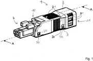
- the FIG. 1 shows a housing 1, which has a first housing part 2 and a second housing part 3 as separate components.
- the first housing part 2 is an upper housing part, which is placed on the second, designed as a housing lower part housing part 3 to form the housing 1.
- the housing parts 1, 2 can be connected to one another via connection means 20, 30.
- the connecting means 20, 30 are formed here as a latching connection, for example, with the second housing part 3 integrally formed latching hooks 30 and corresponding detent openings 20 on the first housing part 2.
- the housing parts 1, 2 are connected to each other by another type of connection means, for example a screw connection.
- the housing 1 has a front-side connector receiving area 10 and a rearward cable receiving area 11 arranged at the other end.
- the FIG. 1 shows that an electrical connector 4 is connected to the housing 1 by arranging a specific portion of the connector 4 within the connector housing portion 10 and fixed therein.
- the housing 1 may also be formed integrally with the connector 4, so that it is the housing of an electrical connector.
- the housing for receiving an electrical connector it is assumed that a housing for receiving an electrical connector.
- the housing 1 has a strain relief device with a latching clip 31, by means of which a cable or an electrical conductor arranged in the interior of the housing 1 is strain-relieved.
- the latching clip 31 is in the FIG. 1 as well as in further Figures 2 and 3 shown in two operating positions in which it is displaceable, but in fact the latching clip 31 is present only once.
- FIG. 2 shows the housing 1 with the electrical connector 4 according to FIG. 1 in a sectional view along the cutting plane AA, as in FIG. 1 located.
- the electrical connector 4 has a plug-in contact region 41, in which the electrical plug contacts of the connector are arranged for contacting with a mating connector.
- the plug contact region 41 protrudes from the housing 1.
- An attachment portion 40 of the electrical connector 4 is disposed in the connector receiving portion 10 of the housing 1 and held therein by the housing parts 2, 3 in a form-fitting manner.
- the strain relief with the locking bracket 31 (again shown in duplicate) and corresponding clamping means 32 on the second housing part 3 and further clamping means 33 on the locking bracket 31 can be seen.
- the clamping means 32, 33 an electric cable is clamped in between and accordingly protected against occurring tensile loads in accordance with actuated latching clip 31.
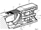
- FIG. 3 shows the in FIG. 2 marked section B in an enlarged view, so that the details of the strain relief and the elastically deflectable flap 5 are even more clearly visible.
- the tab 5 has a root region 52, in which it can be integrally formed on the first housing part 2.
- the tab 5 extends from the root area 52 via a production side already pre-bent portion 51 toward a free end 50 of the tab 5.
- the thickness of the tab 5 is reduced from the root portion 52 in the direction of the free end 50 of the tab fifth
- FIG. 4 shows in side cross-sectional view of the housing 1 and the connector 4 with a cable 6 inserted in the housing 1 with a first cable cross-section. From the cable 6 electrical conductors 60 emerge in the direction of the connector 4 out and are electrically connected there to the plug contacts of the connector 4. It can be seen in particular that the tab 5 is deflected upward and accordingly not in its lower, in the Figures 2 and 3 shown positions remains, but occupies the upper position shown. In this case, the free end 50 of the tab 5 rests on the electrical conductors 60.
- the latching clip 31 of the strain relief device is made of in the Figures 2 and 3 noticeable upper starting position shifted down, so that the cable 6 is clamped between the clamping means 32 on the second housing part 3 and the other clamping means 33 on the locking bracket 31.
- FIG. 5 shows in a similar view as the FIG. 4 the arrangement of a cable 6 in the housing 1, which has a second, larger cross section than the first cross section of the cable 6 of FIG. 4 having. It can be seen that the latching clip 31 is not or only minimally displaced downwards in order to clamp the cable 6 by means of the clamping means 32, 33.
- conductors 60 exit from the cable 6.
- this is again shown in duplicate, namely once in the upper position, as in FIG. 4 , and additionally in a lower position, which would be assumed if no cable 6 or no conductors 60 were inserted.
- FIG. 6 shows the arrangement according to FIG. 4 in a cross section in the plane CC, as in FIG. 4 located. Based on FIG. 6 the operation of the strain relief can be further explained. It can be seen that the latching clip 31 is arranged on pins 26 fastened to the second housing part 3, which have an outwardly directed toothing 25. The latching clip 31 has a corresponding, inwardly directed toothing 35, which is in engagement with the toothing 25. About the teeth 25, 35, the locking bracket 31 can be moved from an upper starting position downwards, wherein after each skip over a tooth of the teeth 25, 35, a fixing of the locking clip 31 against movement upwards takes place.
- the locking clip 31 is manually operable via recesses, which are provided in the first housing part 2, from the outside. It has an actuating region 34 with slit-shaped depressions, into which e.g. a screwdriver for actuating the latching clip 31 can be inserted.
- FIG. 7 shows the arrangement according to FIG. 4 in the section plane DD. Recognizable in turn is the locking between the housing parts 2, 3 via the locking hooks 30 and the latching openings 20. Also visible is the tab 5, which rests with its free end 52 on the electrical conductors 60.
- the tab 5 is formed in a viewing direction in the longitudinal direction of the electrical conductor 60 with a substantially rectangular outer contour.
- the conductor passage is bounded by surface portions 27 of the housing material arranged there, in this case the first housing part 2. In this way it is prevented that a strigdorn can be guided laterally on the tab 5.
- the tab 5 is deflected by the inserted electrical conductor 60 upwards. This results in the lower region, i. below the tab 5 laterally from the electrical conductor a certain amount of space.
- the wall 36 is additionally provided on the second housing part 3 in the lower area to the inner space 12 out rounded wall 36 which is disposed between the tab 5 and the strain relief device with the latch bracket 31. Due to its profiling, the wall 36 permits the passage of the electrical conductors 60 towards the plug-in connector 4, but prevents the passage of a test mandrel in the lower region laterally past the electrical conductors 60.
- additional surface sections are provided by the wall 36, through which the conductor passage is laterally bounded by the tab 5.
Landscapes
- Details Of Connecting Devices For Male And Female Coupling (AREA)
- Connector Housings Or Holding Contact Members (AREA)
Applications Claiming Priority (1)
| Application Number | Priority Date | Filing Date | Title |
|---|---|---|---|
| DE102016101621.7A DE102016101621B4 (de) | 2016-01-29 | 2016-01-29 | Gehäuse für einen elektrischen Steckverbinder |
Publications (2)
| Publication Number | Publication Date |
|---|---|
| EP3200288A1 true EP3200288A1 (fr) | 2017-08-02 |
| EP3200288B1 EP3200288B1 (fr) | 2019-08-21 |
Family
ID=57777550
Family Applications (1)
| Application Number | Title | Priority Date | Filing Date |
|---|---|---|---|
| EP17150986.2A Active EP3200288B1 (fr) | 2016-01-29 | 2017-01-11 | Boîtier de connecteur électrique ou destiné à recevoir un connecteur électrique |
Country Status (3)
| Country | Link |
|---|---|
| EP (1) | EP3200288B1 (fr) |
| CN (2) | CN112003058B (fr) |
| DE (1) | DE102016101621B4 (fr) |
Families Citing this family (1)
| Publication number | Priority date | Publication date | Assignee | Title |
|---|---|---|---|---|
| AU2021292753B2 (en) | 2020-06-18 | 2023-12-21 | Ideal Industries, Inc. | Conductor terminal |
Citations (6)
| Publication number | Priority date | Publication date | Assignee | Title |
|---|---|---|---|---|
| US4632489A (en) * | 1985-11-27 | 1986-12-30 | Custom Cable Assemblies, Inc. | Hood for electronic cable connector |
| EP0280450A2 (fr) * | 1987-02-26 | 1988-08-31 | Molex Incorporated | Connecteur électrique |
| EP0818855A1 (fr) * | 1996-07-12 | 1998-01-14 | Sumitomo Wiring Systems, Ltd. | Connecteur |
| DE202013101929U1 (de) | 2013-05-03 | 2013-06-06 | Wago Verwaltungsgesellschaft Mbh | Zugentlastungsgehäuse |
| DE102012206102A1 (de) * | 2012-04-13 | 2013-10-17 | Tyco Electronics Amp Gmbh | Elektrischer Verbinder |
| US20150162686A1 (en) * | 2012-04-24 | 2015-06-11 | Dongguan Yuqiu Electronics Co., Ltd. | Electric connector for flat conductor and assembly method for electric connector and flat conductor |
Family Cites Families (11)
| Publication number | Priority date | Publication date | Assignee | Title |
|---|---|---|---|---|
| CA1295383C (fr) * | 1988-04-29 | 1992-02-04 | Robert W. Harrington | Connecteur de cables |
| GB8814968D0 (en) * | 1988-06-23 | 1988-07-27 | Electrolux Northern | Improvements in electric appliances |
| EP0352347A1 (fr) | 1988-07-27 | 1990-01-31 | C.A. Weidmüller GmbH & Co. | Connecteur électrique |
| US5422437A (en) * | 1993-04-16 | 1995-06-06 | Hubbell Incorporated | Electrical connector assembly |
| GB9510886D0 (en) | 1995-05-30 | 1995-07-26 | Amp Great Britain | Wire cutting electrical connector having test probe access |
| US6116945A (en) * | 1997-12-30 | 2000-09-12 | The Whitaker Corporation | Microphone connector assembly |
| AT410616B (de) * | 2001-03-27 | 2003-06-25 | Weingartner Bernhard | Elektrischer kabelstecker |
| DE202011005477U1 (de) * | 2011-04-20 | 2011-06-30 | WAGO Verwaltungsgesellschaft mbH, 32423 | Zugentlastungsgehäuse für elektrische Bauteile |
| DE102011051951A1 (de) * | 2011-07-19 | 2013-01-24 | Phoenix Contact Gmbh & Co. Kg | Steckverbinder mit Zugentlastung |
| DE202013105944U1 (de) * | 2013-12-26 | 2014-01-22 | Wago Verwaltungsgesellschaft Mbh | Federkraft-Klemmanschluss und Steckverbinder hiermit |
| GB201403941D0 (en) * | 2014-03-06 | 2014-04-23 | Scolmore Int Ltd | Electrical connector |
-
2016
- 2016-01-29 DE DE102016101621.7A patent/DE102016101621B4/de not_active Expired - Fee Related
-
2017
- 2017-01-11 EP EP17150986.2A patent/EP3200288B1/fr active Active
- 2017-01-25 CN CN202010692487.XA patent/CN112003058B/zh active Active
- 2017-01-25 CN CN201710060986.5A patent/CN107026347B/zh not_active Expired - Fee Related
Patent Citations (6)
| Publication number | Priority date | Publication date | Assignee | Title |
|---|---|---|---|---|
| US4632489A (en) * | 1985-11-27 | 1986-12-30 | Custom Cable Assemblies, Inc. | Hood for electronic cable connector |
| EP0280450A2 (fr) * | 1987-02-26 | 1988-08-31 | Molex Incorporated | Connecteur électrique |
| EP0818855A1 (fr) * | 1996-07-12 | 1998-01-14 | Sumitomo Wiring Systems, Ltd. | Connecteur |
| DE102012206102A1 (de) * | 2012-04-13 | 2013-10-17 | Tyco Electronics Amp Gmbh | Elektrischer Verbinder |
| US20150162686A1 (en) * | 2012-04-24 | 2015-06-11 | Dongguan Yuqiu Electronics Co., Ltd. | Electric connector for flat conductor and assembly method for electric connector and flat conductor |
| DE202013101929U1 (de) | 2013-05-03 | 2013-06-06 | Wago Verwaltungsgesellschaft Mbh | Zugentlastungsgehäuse |
Also Published As
| Publication number | Publication date |
|---|---|
| CN112003058A (zh) | 2020-11-27 |
| CN112003058B (zh) | 2022-05-10 |
| DE102016101621B4 (de) | 2018-10-18 |
| CN107026347B (zh) | 2020-08-18 |
| EP3200288B1 (fr) | 2019-08-21 |
| CN107026347A (zh) | 2017-08-08 |
| DE102016101621A1 (de) | 2017-08-03 |
Similar Documents
| Publication | Publication Date | Title |
|---|---|---|
| DE102006016882B4 (de) | Steckverbinder | |
| DE102011115637B4 (de) | Elektrische Anschlussklemme | |
| DE102011055919B4 (de) | Anschlussklemme | |
| EP2752944A2 (fr) | Borne de raccordement électrique et son procédé de montage | |
| DE102014213659A1 (de) | Gehäuseteil für einen elektrischen Steckverbinder | |
| EP2738884B1 (fr) | Montage d'un dispositif de raccordement | |
| EP3224907B1 (fr) | Connecteur pour films de circuit imprimé flexibles | |
| EP2380241B1 (fr) | Connecteur de contact et connexion par connecteur de contact | |
| EP2606538B1 (fr) | Connecteur | |
| DE102012104857B4 (de) | Elektrische Steckverbindung | |
| DE102015114080B4 (de) | Elektrischer steckverbinder und damit ausgestattete elektrische steckverbindung | |
| EP3849018A1 (fr) | Borne de raccordement de conducteur | |
| DE102006004782B4 (de) | Verfahren zur Herstellung einer Verrastungsvorrichtung für einen elektrischen Kontakt in einem Steckverbinder | |
| EP3200288B1 (fr) | Boîtier de connecteur électrique ou destiné à recevoir un connecteur électrique | |
| DE102016105192B3 (de) | Leiteranschlussklemme | |
| DE102010009807A1 (de) | Anschlussklemmmenanordnung | |
| DE2452091A1 (de) | Vorrichtung zum festklemmen miteinander elektrisch zu verbindender leiter | |
| DE3118574A1 (de) | Elektrisches kontaktstueck sowie elektrische steckeranordnung | |
| EP2067212A1 (fr) | Connecteur à fiches électrique avec guidage | |
| DE102016000384B4 (de) | Mehrpoliger elektrischer Verbinder | |
| EP3123566B1 (fr) | Douille de contact pour prise électrique | |
| DE10227235A1 (de) | Leiteranschluss | |
| AT410616B (de) | Elektrischer kabelstecker | |
| EP3152801B1 (fr) | Pièce de retenue pour contact avec blocage en traction fiable | |
| DE19747115A1 (de) | Elektrische Steckverbinderanordnung und elektrischer Kontakt |
Legal Events
| Date | Code | Title | Description |
|---|---|---|---|
| PUAI | Public reference made under article 153(3) epc to a published international application that has entered the european phase |
Free format text: ORIGINAL CODE: 0009012 |
|
| STAA | Information on the status of an ep patent application or granted ep patent |
Free format text: STATUS: THE APPLICATION HAS BEEN PUBLISHED |
|
| AK | Designated contracting states |
Kind code of ref document: A1 Designated state(s): AL AT BE BG CH CY CZ DE DK EE ES FI FR GB GR HR HU IE IS IT LI LT LU LV MC MK MT NL NO PL PT RO RS SE SI SK SM TR |
|
| AX | Request for extension of the european patent |
Extension state: BA ME |
|
| STAA | Information on the status of an ep patent application or granted ep patent |
Free format text: STATUS: REQUEST FOR EXAMINATION WAS MADE |
|
| 17P | Request for examination filed |
Effective date: 20170815 |
|
| RBV | Designated contracting states (corrected) |
Designated state(s): AL AT BE BG CH CY CZ DE DK EE ES FI FR GB GR HR HU IE IS IT LI LT LU LV MC MK MT NL NO PL PT RO RS SE SI SK SM TR |
|
| STAA | Information on the status of an ep patent application or granted ep patent |
Free format text: STATUS: EXAMINATION IS IN PROGRESS |
|
| 17Q | First examination report despatched |
Effective date: 20180606 |
|
| REG | Reference to a national code |
Ref country code: DE Ref legal event code: R079 Ref document number: 502017002054 Country of ref document: DE Free format text: PREVIOUS MAIN CLASS: H01R0013580000 Ipc: H01R0013520000 |
|
| GRAP | Despatch of communication of intention to grant a patent |
Free format text: ORIGINAL CODE: EPIDOSNIGR1 |
|
| STAA | Information on the status of an ep patent application or granted ep patent |
Free format text: STATUS: GRANT OF PATENT IS INTENDED |
|
| RIC1 | Information provided on ipc code assigned before grant |
Ipc: H01R 13/52 20060101AFI20190218BHEP Ipc: H01R 13/58 20060101ALI20190218BHEP |
|
| INTG | Intention to grant announced |
Effective date: 20190318 |
|
| GRAS | Grant fee paid |
Free format text: ORIGINAL CODE: EPIDOSNIGR3 |
|
| GRAA | (expected) grant |
Free format text: ORIGINAL CODE: 0009210 |
|
| STAA | Information on the status of an ep patent application or granted ep patent |
Free format text: STATUS: THE PATENT HAS BEEN GRANTED |
|
| AK | Designated contracting states |
Kind code of ref document: B1 Designated state(s): AL AT BE BG CH CY CZ DE DK EE ES FI FR GB GR HR HU IE IS IT LI LT LU LV MC MK MT NL NO PL PT RO RS SE SI SK SM TR |
|
| REG | Reference to a national code |
Ref country code: GB Ref legal event code: FG4D Free format text: NOT ENGLISH |
|
| REG | Reference to a national code |
Ref country code: CH Ref legal event code: EP |
|
| REG | Reference to a national code |
Ref country code: DE Ref legal event code: R096 Ref document number: 502017002054 Country of ref document: DE |
|
| REG | Reference to a national code |
Ref country code: AT Ref legal event code: REF Ref document number: 1170816 Country of ref document: AT Kind code of ref document: T Effective date: 20190915 |
|
| REG | Reference to a national code |
Ref country code: IE Ref legal event code: FG4D Free format text: LANGUAGE OF EP DOCUMENT: GERMAN |
|
| REG | Reference to a national code |
Ref country code: LT Ref legal event code: MG4D |
|
| REG | Reference to a national code |
Ref country code: NL Ref legal event code: MP Effective date: 20190821 |
|
| PG25 | Lapsed in a contracting state [announced via postgrant information from national office to epo] |
Ref country code: FI Free format text: LAPSE BECAUSE OF FAILURE TO SUBMIT A TRANSLATION OF THE DESCRIPTION OR TO PAY THE FEE WITHIN THE PRESCRIBED TIME-LIMIT Effective date: 20190821 Ref country code: NO Free format text: LAPSE BECAUSE OF FAILURE TO SUBMIT A TRANSLATION OF THE DESCRIPTION OR TO PAY THE FEE WITHIN THE PRESCRIBED TIME-LIMIT Effective date: 20191121 Ref country code: SE Free format text: LAPSE BECAUSE OF FAILURE TO SUBMIT A TRANSLATION OF THE DESCRIPTION OR TO PAY THE FEE WITHIN THE PRESCRIBED TIME-LIMIT Effective date: 20190821 Ref country code: HR Free format text: LAPSE BECAUSE OF FAILURE TO SUBMIT A TRANSLATION OF THE DESCRIPTION OR TO PAY THE FEE WITHIN THE PRESCRIBED TIME-LIMIT Effective date: 20190821 Ref country code: LT Free format text: LAPSE BECAUSE OF FAILURE TO SUBMIT A TRANSLATION OF THE DESCRIPTION OR TO PAY THE FEE WITHIN THE PRESCRIBED TIME-LIMIT Effective date: 20190821 Ref country code: NL Free format text: LAPSE BECAUSE OF FAILURE TO SUBMIT A TRANSLATION OF THE DESCRIPTION OR TO PAY THE FEE WITHIN THE PRESCRIBED TIME-LIMIT Effective date: 20190821 Ref country code: BG Free format text: LAPSE BECAUSE OF FAILURE TO SUBMIT A TRANSLATION OF THE DESCRIPTION OR TO PAY THE FEE WITHIN THE PRESCRIBED TIME-LIMIT Effective date: 20191121 Ref country code: PT Free format text: LAPSE BECAUSE OF FAILURE TO SUBMIT A TRANSLATION OF THE DESCRIPTION OR TO PAY THE FEE WITHIN THE PRESCRIBED TIME-LIMIT Effective date: 20191223 |
|
| PG25 | Lapsed in a contracting state [announced via postgrant information from national office to epo] |
Ref country code: AL Free format text: LAPSE BECAUSE OF FAILURE TO SUBMIT A TRANSLATION OF THE DESCRIPTION OR TO PAY THE FEE WITHIN THE PRESCRIBED TIME-LIMIT Effective date: 20190821 Ref country code: LV Free format text: LAPSE BECAUSE OF FAILURE TO SUBMIT A TRANSLATION OF THE DESCRIPTION OR TO PAY THE FEE WITHIN THE PRESCRIBED TIME-LIMIT Effective date: 20190821 Ref country code: GR Free format text: LAPSE BECAUSE OF FAILURE TO SUBMIT A TRANSLATION OF THE DESCRIPTION OR TO PAY THE FEE WITHIN THE PRESCRIBED TIME-LIMIT Effective date: 20191122 Ref country code: IS Free format text: LAPSE BECAUSE OF FAILURE TO SUBMIT A TRANSLATION OF THE DESCRIPTION OR TO PAY THE FEE WITHIN THE PRESCRIBED TIME-LIMIT Effective date: 20191221 Ref country code: RS Free format text: LAPSE BECAUSE OF FAILURE TO SUBMIT A TRANSLATION OF THE DESCRIPTION OR TO PAY THE FEE WITHIN THE PRESCRIBED TIME-LIMIT Effective date: 20190821 Ref country code: ES Free format text: LAPSE BECAUSE OF FAILURE TO SUBMIT A TRANSLATION OF THE DESCRIPTION OR TO PAY THE FEE WITHIN THE PRESCRIBED TIME-LIMIT Effective date: 20190821 |
|
| PG25 | Lapsed in a contracting state [announced via postgrant information from national office to epo] |
Ref country code: TR Free format text: LAPSE BECAUSE OF FAILURE TO SUBMIT A TRANSLATION OF THE DESCRIPTION OR TO PAY THE FEE WITHIN THE PRESCRIBED TIME-LIMIT Effective date: 20190821 |
|
| PG25 | Lapsed in a contracting state [announced via postgrant information from national office to epo] |
Ref country code: PL Free format text: LAPSE BECAUSE OF FAILURE TO SUBMIT A TRANSLATION OF THE DESCRIPTION OR TO PAY THE FEE WITHIN THE PRESCRIBED TIME-LIMIT Effective date: 20190821 Ref country code: DK Free format text: LAPSE BECAUSE OF FAILURE TO SUBMIT A TRANSLATION OF THE DESCRIPTION OR TO PAY THE FEE WITHIN THE PRESCRIBED TIME-LIMIT Effective date: 20190821 Ref country code: EE Free format text: LAPSE BECAUSE OF FAILURE TO SUBMIT A TRANSLATION OF THE DESCRIPTION OR TO PAY THE FEE WITHIN THE PRESCRIBED TIME-LIMIT Effective date: 20190821 Ref country code: IT Free format text: LAPSE BECAUSE OF FAILURE TO SUBMIT A TRANSLATION OF THE DESCRIPTION OR TO PAY THE FEE WITHIN THE PRESCRIBED TIME-LIMIT Effective date: 20190821 Ref country code: RO Free format text: LAPSE BECAUSE OF FAILURE TO SUBMIT A TRANSLATION OF THE DESCRIPTION OR TO PAY THE FEE WITHIN THE PRESCRIBED TIME-LIMIT Effective date: 20190821 |
|
| PG25 | Lapsed in a contracting state [announced via postgrant information from national office to epo] |
Ref country code: CZ Free format text: LAPSE BECAUSE OF FAILURE TO SUBMIT A TRANSLATION OF THE DESCRIPTION OR TO PAY THE FEE WITHIN THE PRESCRIBED TIME-LIMIT Effective date: 20190821 Ref country code: SM Free format text: LAPSE BECAUSE OF FAILURE TO SUBMIT A TRANSLATION OF THE DESCRIPTION OR TO PAY THE FEE WITHIN THE PRESCRIBED TIME-LIMIT Effective date: 20190821 Ref country code: SK Free format text: LAPSE BECAUSE OF FAILURE TO SUBMIT A TRANSLATION OF THE DESCRIPTION OR TO PAY THE FEE WITHIN THE PRESCRIBED TIME-LIMIT Effective date: 20190821 Ref country code: IS Free format text: LAPSE BECAUSE OF FAILURE TO SUBMIT A TRANSLATION OF THE DESCRIPTION OR TO PAY THE FEE WITHIN THE PRESCRIBED TIME-LIMIT Effective date: 20200224 |
|
| REG | Reference to a national code |
Ref country code: DE Ref legal event code: R097 Ref document number: 502017002054 Country of ref document: DE |
|
| PLBE | No opposition filed within time limit |
Free format text: ORIGINAL CODE: 0009261 |
|
| STAA | Information on the status of an ep patent application or granted ep patent |
Free format text: STATUS: NO OPPOSITION FILED WITHIN TIME LIMIT |
|
| PG2D | Information on lapse in contracting state deleted |
Ref country code: IS |
|
| 26N | No opposition filed |
Effective date: 20200603 |
|
| PG25 | Lapsed in a contracting state [announced via postgrant information from national office to epo] |
Ref country code: SI Free format text: LAPSE BECAUSE OF FAILURE TO SUBMIT A TRANSLATION OF THE DESCRIPTION OR TO PAY THE FEE WITHIN THE PRESCRIBED TIME-LIMIT Effective date: 20190821 Ref country code: MC Free format text: LAPSE BECAUSE OF FAILURE TO SUBMIT A TRANSLATION OF THE DESCRIPTION OR TO PAY THE FEE WITHIN THE PRESCRIBED TIME-LIMIT Effective date: 20190821 |
|
| REG | Reference to a national code |
Ref country code: CH Ref legal event code: PL |
|
| REG | Reference to a national code |
Ref country code: BE Ref legal event code: MM Effective date: 20200131 |
|
| PG25 | Lapsed in a contracting state [announced via postgrant information from national office to epo] |
Ref country code: LU Free format text: LAPSE BECAUSE OF NON-PAYMENT OF DUE FEES Effective date: 20200111 Ref country code: FR Free format text: LAPSE BECAUSE OF NON-PAYMENT OF DUE FEES Effective date: 20200131 |
|
| PG25 | Lapsed in a contracting state [announced via postgrant information from national office to epo] |
Ref country code: LI Free format text: LAPSE BECAUSE OF NON-PAYMENT OF DUE FEES Effective date: 20200131 Ref country code: BE Free format text: LAPSE BECAUSE OF NON-PAYMENT OF DUE FEES Effective date: 20200131 Ref country code: CH Free format text: LAPSE BECAUSE OF NON-PAYMENT OF DUE FEES Effective date: 20200131 |
|
| PG25 | Lapsed in a contracting state [announced via postgrant information from national office to epo] |
Ref country code: IE Free format text: LAPSE BECAUSE OF NON-PAYMENT OF DUE FEES Effective date: 20200111 |
|
| PGFP | Annual fee paid to national office [announced via postgrant information from national office to epo] |
Ref country code: DE Payment date: 20210129 Year of fee payment: 5 |
|
| GBPC | Gb: european patent ceased through non-payment of renewal fee |
Effective date: 20210111 |
|
| PG25 | Lapsed in a contracting state [announced via postgrant information from national office to epo] |
Ref country code: GB Free format text: LAPSE BECAUSE OF NON-PAYMENT OF DUE FEES Effective date: 20210111 |
|
| PG25 | Lapsed in a contracting state [announced via postgrant information from national office to epo] |
Ref country code: MT Free format text: LAPSE BECAUSE OF FAILURE TO SUBMIT A TRANSLATION OF THE DESCRIPTION OR TO PAY THE FEE WITHIN THE PRESCRIBED TIME-LIMIT Effective date: 20190821 Ref country code: CY Free format text: LAPSE BECAUSE OF FAILURE TO SUBMIT A TRANSLATION OF THE DESCRIPTION OR TO PAY THE FEE WITHIN THE PRESCRIBED TIME-LIMIT Effective date: 20190821 |
|
| PG25 | Lapsed in a contracting state [announced via postgrant information from national office to epo] |
Ref country code: MK Free format text: LAPSE BECAUSE OF FAILURE TO SUBMIT A TRANSLATION OF THE DESCRIPTION OR TO PAY THE FEE WITHIN THE PRESCRIBED TIME-LIMIT Effective date: 20190821 |
|
| REG | Reference to a national code |
Ref country code: DE Ref legal event code: R119 Ref document number: 502017002054 Country of ref document: DE |
|
| PG25 | Lapsed in a contracting state [announced via postgrant information from national office to epo] |
Ref country code: DE Free format text: LAPSE BECAUSE OF NON-PAYMENT OF DUE FEES Effective date: 20220802 |
|
| REG | Reference to a national code |
Ref country code: AT Ref legal event code: MM01 Ref document number: 1170816 Country of ref document: AT Kind code of ref document: T Effective date: 20220111 |
|
| PG25 | Lapsed in a contracting state [announced via postgrant information from national office to epo] |
Ref country code: AT Free format text: LAPSE BECAUSE OF NON-PAYMENT OF DUE FEES Effective date: 20220111 |