EP3199261B1 - Dispositif de fabrication d'armatures - Google Patents
Dispositif de fabrication d'armatures Download PDFInfo
- Publication number
- EP3199261B1 EP3199261B1 EP17155416.5A EP17155416A EP3199261B1 EP 3199261 B1 EP3199261 B1 EP 3199261B1 EP 17155416 A EP17155416 A EP 17155416A EP 3199261 B1 EP3199261 B1 EP 3199261B1
- Authority
- EP
- European Patent Office
- Prior art keywords
- slide
- expander
- transmission means
- actuator
- stop
- Prior art date
- Legal status (The legal status is an assumption and is not a legal conclusion. Google has not performed a legal analysis and makes no representation as to the accuracy of the status listed.)
- Active
Links
- 230000002787 reinforcement Effects 0.000 title claims description 37
- 230000005540 biological transmission Effects 0.000 claims description 27
- 238000004519 manufacturing process Methods 0.000 claims description 8
- 238000003892 spreading Methods 0.000 description 13
- 230000003014 reinforcing effect Effects 0.000 description 12
- 238000003466 welding Methods 0.000 description 3
- 238000000034 method Methods 0.000 description 2
- 230000001419 dependent effect Effects 0.000 description 1
- 238000006073 displacement reaction Methods 0.000 description 1
- 238000007493 shaping process Methods 0.000 description 1
Images


Classifications
-
- B—PERFORMING OPERATIONS; TRANSPORTING
- B21—MECHANICAL METAL-WORKING WITHOUT ESSENTIALLY REMOVING MATERIAL; PUNCHING METAL
- B21F—WORKING OR PROCESSING OF METAL WIRE
- B21F27/00—Making wire network, i.e. wire nets
- B21F27/12—Making special types or portions of network by methods or means specially adapted therefor
- B21F27/121—Making special types or portions of network by methods or means specially adapted therefor of tubular form, e.g. as reinforcements for pipes or pillars
- B21F27/122—Making special types or portions of network by methods or means specially adapted therefor of tubular form, e.g. as reinforcements for pipes or pillars by attaching a continuous stirrup to longitudinal wires
- B21F27/124—Making special types or portions of network by methods or means specially adapted therefor of tubular form, e.g. as reinforcements for pipes or pillars by attaching a continuous stirrup to longitudinal wires applied by rotation
-
- B—PERFORMING OPERATIONS; TRANSPORTING
- B21—MECHANICAL METAL-WORKING WITHOUT ESSENTIALLY REMOVING MATERIAL; PUNCHING METAL
- B21F—WORKING OR PROCESSING OF METAL WIRE
- B21F27/00—Making wire network, i.e. wire nets
- B21F27/08—Making wire network, i.e. wire nets with additional connecting elements or material at crossings
- B21F27/10—Making wire network, i.e. wire nets with additional connecting elements or material at crossings with soldered or welded crossings
-
- B—PERFORMING OPERATIONS; TRANSPORTING
- B21—MECHANICAL METAL-WORKING WITHOUT ESSENTIALLY REMOVING MATERIAL; PUNCHING METAL
- B21F—WORKING OR PROCESSING OF METAL WIRE
- B21F27/00—Making wire network, i.e. wire nets
- B21F27/12—Making special types or portions of network by methods or means specially adapted therefor
- B21F27/121—Making special types or portions of network by methods or means specially adapted therefor of tubular form, e.g. as reinforcements for pipes or pillars
Definitions
- the invention relates to a device for producing reinforcements, in particular of reinforcing baskets for concrete pipes with bell sleeve, according to the preamble of claim 1 (see, eg DE-A-23 60 532 ), as well as a machine for producing reinforcements with such a device.
- a known device is designed as a spreading device having a plurality of adjustable relative to each other in the axial adjustment rods, on each of which a radially adjustable guide for the adjustment of longitudinal bars of the reinforcement is articulated.
- the adjusting rods in turn cooperate with an adjusting plate, which limit a travel of the adjusting rods due to stops on the adjusting rod.
- the object of the invention is to provide an alternative device for producing reinforcements, in particular reinforcing baskets for concrete pipes with a bell socket.
- the invention relates to a device for the production of reinforcements, in particular of reinforcing baskets for concrete pipes with bell sleeve, with a spreading device which has a single Sp Schwarzschieber, wherein the Sp Schwarzschieber is adapted to a radial position of a control element for a longitudinal wire of the reinforcement over a Transfer means of the spreading, in particular during the manufacturing process of the reinforcement to change.
- the transmission means of the spreading device are formed for example as a drive chain and / or as a drive rod. Furthermore, the spreading device on a mold slide, wherein an actuator is provided for movement of the mold slide.
- the essential aspect of the invention is now to be seen in the fact that for a linear movement of the mold slide with respect to the Sp Schwarzschieber the actuator is supported on Sp Schwarzschieber.
- the mold slide is designed such that the radial position of an associated adjusting element for a longitudinal wire of the reinforcement via a transfer means of the spreading device is variable by the mold slide, in particular during the manufacturing process of the reinforcement.
- a change in geometry of the reinforcement in particular of the reinforcing cage, can be realized, advantageously a change in geometry of a cross section of the reinforcement, e.g. from round to oval or vice versa.
- the expansion slide and / or the mold slide is designed, for example, to change a radial position of an associated actuating element along a spoke of a spreader wheel for a longitudinal wire of the reinforcement.
- the expansion slide is moved via a first actuator and the mold slide via a second actuator.
- a spreader wheel for example a main wheel and / or a feed wheel, comprises e.g. between 4 and 48 spokes, between 8 and 40 spokes, between 12 and 36 spokes, between 16 and 32 spokes or between 20 and 28 spokes, especially 24 spokes.
- the Sp Schwarzschieber and the mold slide along the transmission means for moving the same adjusting element are formed, in particular via a same transmission means.
- the Sp Schwarzschieber and the mold slide with the transmission means are fixed, in particular connected in a fixed position.
- the mold slide is relatively movable to the Sp Schwarzschieber on Sp Schwarzschieber, in particular formed on the Sp Schwarzschieber.
- a mold slide forms an actuating unit with the expansion slide Control element or with a transmission means.
- a plurality of actuators are present on a device, in particular, an actuating unit and / or a mold slide is provided for each actuator each spoke of the spreader.
- the device in particular the adjusting unit is designed such that the expansion slide and the mold slide are connected in series one behind the other.
- the actuator is designed as a hydraulic cylinder, as a pneumatic cylinder, as an electric motor and / or as a spindle drive.
- a movement of a mold slide by the actuator is decoupled from a movement of the expansion slide and / or the mold slide driven by the expansion shaft.
- the device has a plurality of independently positionable mold slide.
- the device can form the cross-section of the reinforcement round, oval, rectangular, square or polygonal by the independently positionable mold slide.
- the mold slides are independently movable relative to the expansion slide.
- each mold slide has its own actuator. It is also conceivable that all mold slides are coupled together and / or a single mold slide is present. It is also advantageous that all mold slides are movable by a single actuator relative to the expansion slide.
- a mold slide is formed on the device such that by changing a position of the mold slide relative to the expansion slide a radial Position of the associated actuating element along a spoke relative to a radial position of a further actuating element along a further spoke, in particular during the manufacturing process of the reinforcement is changeable.
- the spreading device comprises a plurality of mold slides, wherein the transmission means of the spreading device comprises a plurality of stop elements, wherein the spreading device comprises a stop element in the form of a former, wherein the former forms a driver for a first stop member of a mold slide, and wherein in particular for each mold slide a former is present on the transmission means.
- a maximum difference of a radial position of an actuating element can be predetermined to a further radial position of a further adjusting element.
- a difference of a distance of an actuating element from a rotation axis of the expansion shaft to a further distance of a further adjusting element to the axis of rotation of the expansion shaft is understood.
- a maximum distance of a greatest distance to a rotation axis of the spreader wheel at a smallest distance to a rotation axis of the spreader wheel of a cross section of the reinforcement during production can be predetermined.
- the actuator comprises the former.
- the former is positionally fixed to the transmission means.
- Another advantageous proposal of the invention is that all transmission means are movably guided with respect to the expansion slide.
- the expansion slide and / or the coupled Form slide exclusively via a stop element with the transmission means.
- the Sp Schwarzschieber and / or the mold slide is movable relative to the transfer means positionable.
- a transmission means is movably guided on the expansion slide and / or on a mold slide.
- the expansion slide and / or the mold slide for example, couple exclusively with a setting process of the associated actuating element with a transmission means and / or with a stop element of a transmission means.
- the spreading device has a mold slide, wherein the expansion slide is movably guided on the transmission means, wherein a stop element is fixed to the transmission means, which can be clamped between the expansion slide and a mold slide.
- the einklemmbare stop element is designed as a guide element.
- at least two guide elements are provided, each guide element can be clamped in each case between the Sp Schwarzschieber and a mold slide.
- the guide element forms a driver for a first stop surface of the expansion element and for a second stop member of the mold slide.
- the second stop member of the mold slide is preferably arranged opposite the first stop member.
- a stop element positionally fixed to the transmission means available.
- the expansion slide and a mold slide couple via a stop element with the transmission means.
- a single mold slide couples via a single stop element with one or more transmission means, preferably with a drive chain or a drive rod.
- an actuator is a guide element includes.
- a second cylinder chamber of a cylinder of the actuator is designed such that the cylinder, in particular the cylinder chamber forms the guide element and / or the driver.
- the spreading device has a stop element in the form of a Wegbe dictionaryrs
- the Wegbebankr forms a driver for a second stop surface of the Sp Schwarzschiebers
- the Wegbeskyr specifies a maximum distance between a first stop member of the mold slide and the second stop surface of the Sp Schwarzschiebers.
- the travel limiter in particular provides a maximum distance between the first stop member of the mold slide on the former and the second stop surface of the expansion slide. By this distance, a maximum radial position difference of the adjusting elements is predetermined to each other.
- the spreading device comprises a single travel limiter. It is also conceivable that an actuator has a Wegbegrenzer.
- the two abutment surfaces of the expansion element are present opposite to the expansion element.
- the actuator is designed as a double-acting cylinder.
- the double-acting cylinder is e.g. designed as a hydraulic cylinder or as a pneumatic cylinder. It is conceivable that the double-acting cylinder comprises the former.
- a stroke length of a first cylinder chamber of the cylinders is e.g. configured differently to each other, that by the stroke lengths of the cylinder, a maximum difference of a radial position of an actuating element to a further radial position of a further adjusting element can be predetermined.
- the expansion slide and a Form slide are driven by a Sp Drownwelle the device in particular separately from each other.
- the expansion shaft can form the actuator.
- the expansion slide and the mold slide can be present on the expansion shaft in such a way that the expansion shaft can move the mold slide and the expansion slide separately from one another.
- a position of a stop element along the transfer means is changeable.
- a position of a former, a Wegbegrenzers and / or a guide element is variable, in particular along a drive chain.
- a distance between each of a former and a guide element along the transfer means is changeable.
- a distance between in each case a guide element and a Wegbegrenzer along the transmission means is constant and unchangeable.
- a first distance of a first former to a first guide element along a first drive chain is not equal to a second distance of a second former to a second guide element along a second drive chain.
- a change of shape of the reinforcement cage is e.g. from round to oval or vice versa in the assembled state of the device on the machine feasible.
- all distances between the formers and the guide elements are the same. Thereby, a change in size of the reinforcing cage shape, e.g. the reinforcement cage diameter can be realized.
- a distance between the guide elements and a Wegbe dictionaryr is the same.
- a first distance of a first guide element to a first travel limiter along a first drive chain is the same a second distance of a second guide element to a second Wegbeskyr along a second drive chain.
- a maximum distance of a radial position of a first actuating element to a radial position of a second actuating element can be predetermined.
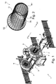
- a machine 1 for producing a reinforcing cage 10 comprises a device 2 according to the invention, which is formed on the main wheel 3 in the region of a main wheel 3 of the machine 1 is.
- the main wheel 3 is fixed to a main frame 4, in particular fixed in position to the main frame 4.
- the machine 1 comprises a spreading shaft 5, a spreader 6 and a feed carriage 7 with a feed wheel 8, which is mounted linearly movable on guide rails 9 ( FIG. 1 ).
- a spoke 14 is present, along which an adjusting element 15 is mounted displaceably in the radial direction, perpendicular to a longitudinal axis L of the expansion shaft 5. Furthermore, a wire guide tube 16 is arranged on the adjusting element 15, which is intended to guide a longitudinal wire 34 of the reinforcing cage 10, in particular parallel to the longitudinal axis L, to the actuating element 15 ( FIG. 3 ). In the region of the actuating element 15, a welding device for welding the longitudinal wire 34 with a transverse wire 35 of the reinforcing cage 10 is arranged (welding device not shown, FIG. 2 ).
- the device 2 comprises a Sp Drschieber 11, a mold slide 12 and a transmission means in the form of a chain 13.
- the chain 13 is formed for example as an endless chain, ie ends of the chain 13 are connected together.
- the chain 13 is movably guided via chain deflections 17, 18, 19 a, 19 b and connects the adjusting element 15 with an actuating unit 20, which consists of the mold slide 12 and the expansion slide 11.
- the chain 13 is fixedly connected to the actuating element 15.
- FIG. 3 a single actuator 20 with chain 13 and associated actuator 15 is shown.
- FIG. 4 shows the arrangement FIG. 3 in a simplified representation, wherein the view is a cross section parallel to the longitudinal axis L of the expansion shaft 5 through the spreader shaft 5 and the main wheel 3.
- FIGS. 5, 7 . 9 and 11 show two different cross sections parallel to the expansion shaft 5 through the device 2 in a simplified representation.
- three chains 13a, 13b, 13c are respectively shown, which Stop elements in the form of a former 27a, 27b, a Wegbegrenzers 26 and guide elements 24a, 24b, 24c include.
- the shapers 27a, 27b have different shapes, eg, the shapers 27a, 27b are formed to have different lengths along the longitudinal axis L of the straddle shaft 5.
- the shapers 27a, 27b can be displaceably mounted on the chains 13a, 13b. It is also conceivable that the stop elements, for example, along a chain 13a, 13b, 13c are fixed in position fixed, for example, to the chain 13a, 13b, 13c are clamped.
- each chain 13a, 13b, 13c is in particular firmly coupled to an actuating element 15a, 15b or 15c ( FIGS. 6, 8 . 10 ).
- the chain 13a, 13b, 13c has a rod-shaped portion 21a, 21b, 21c.
- the chain 13a, 13b, 13c is movably mounted in a parallel direction X1 or X2 to the longitudinal axis L of the expansion shaft 5 on the spreader 11 and on the form slide 12.
- On the rod-shaped portion 21a, 21b, 21c of the chain 13a, 13b, 13c is between a first stop surface 22 of the Sp Schwarzschiebers 11 and a first stop member 23 of the mold slide 12, a guide element 24a, 24b, 24c position fixed in particular parallel to the longitudinal axis L of the expansion shaft 5 to the Chains 13a, 13b, 13c attached.
- the guide member 24a, 24b, 24c is e.g. as a driver with driving surfaces 28a, 28b, 28c, 29a, 29b, 29c for the expansion slide 11 and the mold slide 12 is formed.
- a second stop surface 25 is present.
- a Wegbebankr 26 is mounted fixed in position, wherein this on the, the second stop surface 25 facing side of the Sp Schwarzschiebers 11 is present, so that the abutment surfaces 22, 25 of the expansion slide 11 are formed between the Wegbeskyr 26 and the mold slide 12.
- the device 2 is designed such that a single chain 13a includes a travel limiter 26.
- the rod-shaped sections 21a, 21b form sensor 27a, 27b arranged fixed in position.
- the formers 27a, 27b may be formed differently in size, for example, in particular, the formers 27a, 27b attached to the rod-shaped portions 21a, 21b that driving surfaces 31a, 31b of the formers 27a, 27b different distances to the driving surfaces 28a, 28b the guide elements 24a, 24b have.
- the shapers 27a, 27b are displaceably provided on the chains 13a, 13b, the shapers 27a, 27b can abut on a carrier element 36a, 36b of the chains 13a, 13b, the carrier elements 36a, 36b being fixed in position in the direction X1, X2 against the chains 13a , 13b are present.
- the expansion slide 11 is mounted such that it can be driven in a displaceable manner by the expansion shaft 5 in a direction X1 or X2 parallel to the longitudinal axis L of the expansion shaft 5.
- the mold slide 12 is mounted in a direction X1 or X2 parallel to the longitudinal axis L of the expansion shaft 5 movable on the expansion slide 11. Via an actuator 30, which is formed between the Sp Schwarzschieber 11 and the mold slide 12, a position of the mold slide 12 relative to the Sp Schwarzschieber 11 is variable.
- FIGS. 6, 8 . 10 are schematically actuating elements 15a, 15b, 15c on the main wheel 3 on spokes 14a, 14b, 14c shown.
- the reinforcing cage 10 for a reinforcing tube is composed of longitudinal wires 34 and transverse wires 35.
- the reinforcement cage can have three different main geometries in cross-section perpendicular to a longitudinal axis.
- a first main geometry R1 is circular with a first radius
- a second main geometry O is oval
- a third main geometry R2 is again circular with a second radius which is larger in relation to the first radius of the main geometry R1 ( FIG. 2 ).
- the device 2 is designed to move adjusting elements of the machine 1 in such a way that the reinforcing cage 10, as in FIG FIG. 2 can be produced shown.
- the Sp Gillschieber 11 and the mold slide 12 for example, as in the FIGS. 5, 7 . 9 and 11 represented, parallel to a longitudinal axis L of the expansion shaft 5 on the expansion shaft 5 method.
- adjusting operations of the expansion slide 11 and of the mold slide 12 and thus of the adjusting elements 15a, 15b, 15c for making the reinforcement cage 10 on the machine 1:
- a starting position FIG. 5
- the mold slide 12 In a starting position ( FIG. 5 ) is the mold slide 12 so moved up to the Sp Schwarzschieber 11, via the actuator 30 so that the mold slide 12 advantageously clamps the guide elements 24a, 24b, 24c between its first stop member 23 and the first stop surface 22 of the Sp Schwarzschiebers.
- the guide elements 24a, 24b, 24c have in the starting position all a same starting position S along a longitudinal axis L of the spreader shaft 5 on the spreader shaft 5.
- the distance between the mold slide 12 and the expansion slide 11 is changed via the actuator 30.
- the expansion slide 11 changes its position relative to the starting position S. along the longitudinal axis L of the expansion shaft. 5
- the mold slide 12 is pushed away in the direction X1 parallel to the longitudinal axis L by the expansion slide 11 by the actuator 30.
- the mold slide 12 strikes a driving face 31a, 32a of the shaping elements 27a, 27b in this movement after a shorter or longer travel distance with its second stop element 32 formed opposite the first stop element 23.
- the mold slide 12 moves the chains 13a, 13b, 13c differently as it moves in the direction X1.
- the chain 13a is moved along the full movement length of the mold slide 12 in the direction X1, since the mold slide 12 is already in the starting position with its second stop member 32 abuts the driving surface 31a. Accordingly, the actuator 15a changes its position along the spoke 14a toward a larger radius.
- the chain 15b is moved very short compared to the chain 15a. Accordingly, the radius of the control element 15b increases slightly.
- the chain 15c is not moved at all, since the mold slide 12 with its second stop member 32 meets no resistance or attack. Accordingly, the radius of the actuating element 15c likewise does not change ( FIG. 8 ). It would also be conceivable that the device 2 is designed turned over, so that the adjusting elements 15a, 15b would be moved in the opposite direction and would reduce the radius of the adjusting elements 15a, 15b.
- the mold slide 12 can be moved until the Wegbeskyr 26 abuts with its stop against the second stop surface 25 of the Speizschiebers 11. As a result, a maximum travel of the mold slide 12 is limited relative to the Sp Schwarzschieber 11. As a result, a maximum difference of a radius of an actuating element is set to a further actuator.
- the expansion slide 11 with its first stop face 22 only at the end of its movement reaches the driving face 19a of the guide element 24a, with which the chain 13a remains unmoved in this case ( FIG. 9, 11 ).
- the actuator 15a remains along the spoke 14a in this movement of the Sp Schwarzschiebers 11 on its position on the spoke 14a and the other two adjusting elements 15b, 15c are moved to a position with the same radius as the actuator 15a on the spokes 14b, 14c.
- the circular geometry R2 is realized with a larger radius ( FIG. 10 ).
- the distance between the expansion slide 11 and the mold slide 12 is held by the actuator 30, for example, so that the mold slide 12 maintains a fixed, identical position relative to the expansion slide 11.
- the Sp Schwarzschieber 11 for example driven by the expansion shaft 5 in the direction X2 parallel to the longitudinal axis L of the expansion shaft 5 is moved back so that the guide elements 24a, 24b, 24c are again at the height of the starting position S and the adjusting elements thus also back to their original position on the spokes 14a, 14b, 14c are located.
Claims (10)
- Dispositif (2) de fabrication d'armatures, notamment de cages d'armatures (10) pour tuyaux en béton pourvus d'un emboîtement en cloche, comprenant un dispositif d'expansion (20) qui présente un unique poussoir d'expansion (11), le poussoir d'expansion (11) étant conçu pour modifier une position radiale d'un élément de réglage (15, 15a, 15b, 15c) pour un fil longitudinal (34) de l'armature (10) par l'intermédiaire d'un moyen de transmission (13, 13a, 13b, 13c) du dispositif d'expansion (20), notamment pendant le procédé de fabrication de l'armature (10), le dispositif d'expansion (20) présentant un poussoir de forme (12), un mécanisme de commande (30) étant prévu pour déplacer le poussoir de forme (12), caractérisé en ce que le mécanisme de commande (30) s'appuie sur le poussoir d'expansion (11) pour un mouvement linéaire du poussoir de forme (12) par rapport au poussoir d'expansion (11).
- Dispositif (2) selon la revendication 1, caractérisé en ce que le dispositif (2) présente plusieurs poussoirs de forme (12) pouvant être positionnés indépendamment les uns des autres.
- Dispositif (2) selon la revendication 1, caractérisé en ce que les moyens de transmission (13, 13a, 13b, 13c) du dispositif d'expansion (20) présentent plusieurs éléments de butée, le dispositif d'expansion (20) comprenant un élément de butée sous la forme d'un donneur de forme (27a, 27b), le donneur de forme (27a, 27b) formant un entraîneur pour un premier organe de butée (32) d'un poussoir de forme (12), et un donneur de forme (27a, 27b) étant présent, pour chaque poussoir de forme (12), sur les moyens de transmission (13, 13a, 13b, 13c).
- Dispositif (2) selon l'une des revendications 1 à 3, caractérisé en ce que tous les moyens de transmission (13, 13a, 13b, 13c) sont guidés mobiles par rapport au poussoir d'expansion (11).
- Dispositif (2) selon l'une des revendications 1 à 4, caractérisé en ce que le poussoir d'expansion (11) est guidé mobile sur les moyens de transmission (13, 13a, 13b, 13c), un élément de butée (24a, 24b, 24c) étant fixé sur les moyens de transmission (13, 13a, 13b, 13c) et pouvant être bloqué entre le poussoir d'expansion (11) et le poussoir de forme (12).
- Dispositif (2) selon l'une des revendications précédentes, caractérisé en ce que le dispositif d'expansion (20) présente un élément de butée sous la forme d'un limitateur de course (26), le limitateur de course (26) formant un entraîneur (33) pour une deuxième surface de butée (25) du poussoir d'expansion (11), le limitateur de course (26) prédéfinissant une distance maximale entre un premier et/ou un deuxième organe de butée (22, 32) du poussoir de forme (12) et la deuxième surface de butée (25) du poussoir d'expansion (11).
- Dispositif (2) selon l'une des revendications précédentes, caractérisé en ce que le mécanisme de commande (30) est conçu sous la forme d'un cylindre à double effet.
- Dispositif (2) selon l'une des revendications précédentes, caractérisé en ce que le poussoir d'expansion (11) et un poussoir de forme (12) sont entraînés, notamment indépendamment l'un de l'autre, par un axe d'expansion (5) du dispositif (2).
- Dispositif (2) selon l'une des revendications précédentes, caractérisé en ce qu'une position d'un élément de butée (24a, 24b, 24c, 26, 27a, 27b) le long des moyens de transmission (13,13a, 13b, 13c) peut être modifiée.
- Machine (1) pour fabriquer des armatures (10) avec un dispositif (2) selon l'une des revendications précédentes.
Applications Claiming Priority (1)
| Application Number | Priority Date | Filing Date | Title |
|---|---|---|---|
| DE102016108098.5A DE102016108098A1 (de) | 2016-05-02 | 2016-05-02 | Vorrichtung zur Herstellung von Bewehrungen |
Publications (3)
| Publication Number | Publication Date |
|---|---|
| EP3199261A2 EP3199261A2 (fr) | 2017-08-02 |
| EP3199261A3 EP3199261A3 (fr) | 2017-09-06 |
| EP3199261B1 true EP3199261B1 (fr) | 2018-07-11 |
Family
ID=58018094
Family Applications (1)
| Application Number | Title | Priority Date | Filing Date |
|---|---|---|---|
| EP17155416.5A Active EP3199261B1 (fr) | 2016-05-02 | 2017-02-09 | Dispositif de fabrication d'armatures |
Country Status (9)
| Country | Link |
|---|---|
| US (1) | US10710144B2 (fr) |
| EP (1) | EP3199261B1 (fr) |
| CN (1) | CN109070182B (fr) |
| CA (1) | CA3020417C (fr) |
| DE (1) | DE102016108098A1 (fr) |
| ES (1) | ES2690520T3 (fr) |
| RU (1) | RU2716336C1 (fr) |
| WO (1) | WO2017190855A1 (fr) |
| ZA (1) | ZA201806750B (fr) |
Families Citing this family (1)
| Publication number | Priority date | Publication date | Assignee | Title |
|---|---|---|---|---|
| BR112022022186A2 (pt) * | 2020-07-02 | 2023-01-17 | Mbk Maschb Gmbh | Dispositivo para produção de um reforço de malha metálica |
Family Cites Families (13)
| Publication number | Priority date | Publication date | Assignee | Title |
|---|---|---|---|---|
| SU435888A1 (ru) * | 1972-02-23 | 1974-07-15 | Установка для изготовления арматурныхкаркасов | |
| DE2360532A1 (de) * | 1973-12-05 | 1975-06-12 | Georg Pfender | Maschine zur herstellung von bewehrungskoerpern fuer betonrohre |
| FR2286681A1 (fr) * | 1974-10-03 | 1976-04-30 | Tuyaux Bonna | Machine pour la realisation automatique de cages d'armature notamment pour tuyaux en beton arme |
| DE2946297C2 (de) * | 1979-11-16 | 1986-08-07 | Mbk Maschinenbau Gmbh, 7964 Kisslegg | Maschine zur Herstellung von Bewehrüngskörpern für Betonrohre |
| DE3422420A1 (de) * | 1984-06-16 | 1985-12-19 | Mbk Maschinenbau Gmbh, 7964 Kisslegg | Maschine zur herstellung von bewehrungskoerpern fuer betonrohre |
| SU1337176A1 (ru) * | 1984-08-25 | 1987-09-15 | Молдавский Научно-Исследовательский И Проектно-Конструкторский Институт Строительных Материалов | Автоматическа лини дл изготовлени арматурных каркасов |
| DE59204507D1 (de) * | 1992-03-07 | 1996-01-11 | Mbk Maschinenbau Gmbh | Maschine und Verfahren zum Herstellen von Bewehrungskörben für Betonrohre. |
| DE19814091A1 (de) * | 1998-03-30 | 1999-10-07 | Mbk Maschinenbau Gmbh | Vorrichtung zur Herstellung von Bewehrungskörben für Rechteckrohre aus Beton |
| AUPP758898A0 (en) * | 1998-12-10 | 1999-01-07 | Barden, Wayne | An apparatus for making reinforcing cages for reinforcing concrete |
| DE102004041736A1 (de) * | 2004-08-28 | 2006-03-02 | Ed. Züblin Ag | Maschine zur kontinuierlichen Herstellung von Bewehrungskörben, besonders mit nichtkreisförmigem Querschnitt |
| US20080257445A1 (en) * | 2007-04-20 | 2008-10-23 | Claudio Subacchi | Method And System For Manufacture Of A Wire Cage |
| CN201500756U (zh) * | 2009-06-01 | 2010-06-09 | 四平市英力建筑机械有限公司 | 可调式钢筋笼成型机 |
| WO2014184787A1 (fr) * | 2013-05-17 | 2014-11-20 | Schnell S.P.A. | Appareil et procédé pour fabriquer des cages métalliques pour des piliers coniques |
-
2016
- 2016-05-02 DE DE102016108098.5A patent/DE102016108098A1/de not_active Withdrawn
-
2017
- 2017-02-09 WO PCT/EP2017/052896 patent/WO2017190855A1/fr active Application Filing
- 2017-02-09 EP EP17155416.5A patent/EP3199261B1/fr active Active
- 2017-02-09 ES ES17155416.5T patent/ES2690520T3/es active Active
- 2017-02-09 CN CN201780027167.9A patent/CN109070182B/zh active Active
- 2017-02-09 RU RU2018141825A patent/RU2716336C1/ru active
- 2017-02-09 CA CA3020417A patent/CA3020417C/fr active Active
-
2018
- 2018-10-10 ZA ZA2018/06750A patent/ZA201806750B/en unknown
- 2018-10-24 US US16/169,017 patent/US10710144B2/en active Active
Non-Patent Citations (1)
| Title |
|---|
| None * |
Also Published As
| Publication number | Publication date |
|---|---|
| US10710144B2 (en) | 2020-07-14 |
| DE102016108098A1 (de) | 2017-11-02 |
| CN109070182A (zh) | 2018-12-21 |
| CN109070182B (zh) | 2021-04-30 |
| CA3020417A1 (fr) | 2017-11-09 |
| ZA201806750B (en) | 2024-02-28 |
| EP3199261A3 (fr) | 2017-09-06 |
| WO2017190855A1 (fr) | 2017-11-09 |
| ES2690520T3 (es) | 2018-11-21 |
| CA3020417C (fr) | 2021-01-19 |
| EP3199261A2 (fr) | 2017-08-02 |
| US20190118243A1 (en) | 2019-04-25 |
| BR112018071773A2 (pt) | 2019-02-19 |
| RU2716336C1 (ru) | 2020-03-11 |
Similar Documents
| Publication | Publication Date | Title |
|---|---|---|
| EP2289643B1 (fr) | Dispositif pour le pliage de longues pièces usinées | |
| CH652947A5 (de) | Drahtbiegemaschine. | |
| EP3769923A1 (fr) | Rail de guidage pour une tronçonneuse à chaîne et procédé de fabrication d'un rail de guidage | |
| DE102011053676A1 (de) | Rohrbiegemaschine | |
| EP3199261B1 (fr) | Dispositif de fabrication d'armatures | |
| EP2380674A2 (fr) | Tête de pliage extensible | |
| DE4103134C2 (de) | Einrichtung zum Herstellen von gebogenen Abschnitten an einem Rohr, insbesondere zur Herstellung einer Rohrschlange | |
| DE102011000845B4 (de) | Verfahren zum Biegen und axialen Stauchen eines Rohres und Vorrichtung hierzu | |
| DE102009024406A1 (de) | Rotationsbiegewerkzeug mit Exzenterklemmung | |
| DE102014212732A1 (de) | Verfahren und Anstauchvorrichtung zum Herstellen von abgesetzten Werkstücken, wie Wellen oder Stäbe | |
| DE102006062242A1 (de) | Formteil | |
| EP3867038B1 (fr) | Machine à onduler et procédé pour la modification d'une machine à onduler | |
| EP2205370B1 (fr) | Procede et dispositif de fabrication d'un corps creux et corps creux | |
| EP2072159B1 (fr) | Dispositif de pliage, notamment pour composants tubulaires | |
| DE102008048176B4 (de) | Vorrichtung zum Andrücken eines Balges gegen eine Seitenwand eines Reifenrohlings bei einer Reifenherstellung | |
| DE102016007466A1 (de) | Biegbarer Formkern und zugeordnetes Werkzeug | |
| EP2981373B1 (fr) | Procédé et dispositif de formage pour un corps façonné en fil, ainsi que corps façonné en fil | |
| EP3190306B1 (fr) | Appareil et procede de production d'un coussinet | |
| DE102011122144B4 (de) | Vorrichtung und Verfahren zur spanlosen, axial umformenden Ausbildung einer Innenverzahnung an einem Werkstück | |
| EP4338905A1 (fr) | Dispositif et procédé de traitement d'un matériau | |
| DE10122763B4 (de) | Vorrichtung zur Herstellung von Querwellen an einem Metallrohr | |
| EP1388689A2 (fr) | Méthode et dispositiv pour fabriquer d'un barrilet de commande | |
| EP2637810A2 (fr) | Outil pour l'usinage d'une pièce | |
| DE2305869A1 (de) | Maschine zum biegen von rohren zu rohrschlangen | |
| DE102014114705A1 (de) | Verfahren zur Herstellung eines Drahtformkörpers |
Legal Events
| Date | Code | Title | Description |
|---|---|---|---|
| PUAI | Public reference made under article 153(3) epc to a published international application that has entered the european phase |
Free format text: ORIGINAL CODE: 0009012 |
|
| STAA | Information on the status of an ep patent application or granted ep patent |
Free format text: STATUS: REQUEST FOR EXAMINATION WAS MADE |
|
| 17P | Request for examination filed |
Effective date: 20170209 |
|
| AK | Designated contracting states |
Kind code of ref document: A2 Designated state(s): AL AT BE BG CH CY CZ DE DK EE ES FI FR GB GR HR HU IE IS IT LI LT LU LV MC MK MT NL NO PL PT RO RS SE SI SK SM TR |
|
| AX | Request for extension of the european patent |
Extension state: BA ME |
|
| PUAL | Search report despatched |
Free format text: ORIGINAL CODE: 0009013 |
|
| STAA | Information on the status of an ep patent application or granted ep patent |
Free format text: STATUS: EXAMINATION IS IN PROGRESS |
|
| AK | Designated contracting states |
Kind code of ref document: A3 Designated state(s): AL AT BE BG CH CY CZ DE DK EE ES FI FR GB GR HR HU IE IS IT LI LT LU LV MC MK MT NL NO PL PT RO RS SE SI SK SM TR |
|
| AX | Request for extension of the european patent |
Extension state: BA ME |
|
| RIC1 | Information provided on ipc code assigned before grant |
Ipc: B21F 27/12 20060101AFI20170731BHEP Ipc: B21F 27/10 20060101ALN20170731BHEP |
|
| 17Q | First examination report despatched |
Effective date: 20170822 |
|
| RBV | Designated contracting states (corrected) |
Designated state(s): AL AT BE BG CH CY CZ DE DK EE ES FI FR GB GR HR HU IE IS IT LI LT LU LV MC MK MT NL NO PL PT RO RS SE SI SK SM TR |
|
| RIC1 | Information provided on ipc code assigned before grant |
Ipc: B21F 27/10 20060101ALN20171220BHEP Ipc: B21F 27/12 20060101AFI20171220BHEP |
|
| GRAP | Despatch of communication of intention to grant a patent |
Free format text: ORIGINAL CODE: EPIDOSNIGR1 |
|
| STAA | Information on the status of an ep patent application or granted ep patent |
Free format text: STATUS: GRANT OF PATENT IS INTENDED |
|
| INTG | Intention to grant announced |
Effective date: 20180126 |
|
| GRAS | Grant fee paid |
Free format text: ORIGINAL CODE: EPIDOSNIGR3 |
|
| GRAA | (expected) grant |
Free format text: ORIGINAL CODE: 0009210 |
|
| STAA | Information on the status of an ep patent application or granted ep patent |
Free format text: STATUS: THE PATENT HAS BEEN GRANTED |
|
| AK | Designated contracting states |
Kind code of ref document: B1 Designated state(s): AL AT BE BG CH CY CZ DE DK EE ES FI FR GB GR HR HU IE IS IT LI LT LU LV MC MK MT NL NO PL PT RO RS SE SI SK SM TR |
|
| REG | Reference to a national code |
Ref country code: GB Ref legal event code: FG4D Free format text: NOT ENGLISH |
|
| REG | Reference to a national code |
Ref country code: CH Ref legal event code: EP |
|
| REG | Reference to a national code |
Ref country code: AT Ref legal event code: REF Ref document number: 1016359 Country of ref document: AT Kind code of ref document: T Effective date: 20180715 |
|
| REG | Reference to a national code |
Ref country code: IE Ref legal event code: FG4D Free format text: LANGUAGE OF EP DOCUMENT: GERMAN |
|
| REG | Reference to a national code |
Ref country code: DE Ref legal event code: R096 Ref document number: 502017000068 Country of ref document: DE |
|
| REG | Reference to a national code |
Ref country code: NL Ref legal event code: MP Effective date: 20180711 |
|
| REG | Reference to a national code |
Ref country code: ES Ref legal event code: FG2A Ref document number: 2690520 Country of ref document: ES Kind code of ref document: T3 Effective date: 20181121 |
|
| REG | Reference to a national code |
Ref country code: LT Ref legal event code: MG4D |
|
| PG25 | Lapsed in a contracting state [announced via postgrant information from national office to epo] |
Ref country code: NL Free format text: LAPSE BECAUSE OF FAILURE TO SUBMIT A TRANSLATION OF THE DESCRIPTION OR TO PAY THE FEE WITHIN THE PRESCRIBED TIME-LIMIT Effective date: 20180711 |
|
| PG25 | Lapsed in a contracting state [announced via postgrant information from national office to epo] |
Ref country code: NO Free format text: LAPSE BECAUSE OF FAILURE TO SUBMIT A TRANSLATION OF THE DESCRIPTION OR TO PAY THE FEE WITHIN THE PRESCRIBED TIME-LIMIT Effective date: 20181011 Ref country code: SE Free format text: LAPSE BECAUSE OF FAILURE TO SUBMIT A TRANSLATION OF THE DESCRIPTION OR TO PAY THE FEE WITHIN THE PRESCRIBED TIME-LIMIT Effective date: 20180711 Ref country code: PL Free format text: LAPSE BECAUSE OF FAILURE TO SUBMIT A TRANSLATION OF THE DESCRIPTION OR TO PAY THE FEE WITHIN THE PRESCRIBED TIME-LIMIT Effective date: 20180711 Ref country code: IS Free format text: LAPSE BECAUSE OF FAILURE TO SUBMIT A TRANSLATION OF THE DESCRIPTION OR TO PAY THE FEE WITHIN THE PRESCRIBED TIME-LIMIT Effective date: 20181111 Ref country code: RS Free format text: LAPSE BECAUSE OF FAILURE TO SUBMIT A TRANSLATION OF THE DESCRIPTION OR TO PAY THE FEE WITHIN THE PRESCRIBED TIME-LIMIT Effective date: 20180711 Ref country code: BG Free format text: LAPSE BECAUSE OF FAILURE TO SUBMIT A TRANSLATION OF THE DESCRIPTION OR TO PAY THE FEE WITHIN THE PRESCRIBED TIME-LIMIT Effective date: 20181011 Ref country code: LT Free format text: LAPSE BECAUSE OF FAILURE TO SUBMIT A TRANSLATION OF THE DESCRIPTION OR TO PAY THE FEE WITHIN THE PRESCRIBED TIME-LIMIT Effective date: 20180711 Ref country code: FI Free format text: LAPSE BECAUSE OF FAILURE TO SUBMIT A TRANSLATION OF THE DESCRIPTION OR TO PAY THE FEE WITHIN THE PRESCRIBED TIME-LIMIT Effective date: 20180711 |
|
| PG25 | Lapsed in a contracting state [announced via postgrant information from national office to epo] |
Ref country code: AL Free format text: LAPSE BECAUSE OF FAILURE TO SUBMIT A TRANSLATION OF THE DESCRIPTION OR TO PAY THE FEE WITHIN THE PRESCRIBED TIME-LIMIT Effective date: 20180711 Ref country code: HR Free format text: LAPSE BECAUSE OF FAILURE TO SUBMIT A TRANSLATION OF THE DESCRIPTION OR TO PAY THE FEE WITHIN THE PRESCRIBED TIME-LIMIT Effective date: 20180711 Ref country code: LV Free format text: LAPSE BECAUSE OF FAILURE TO SUBMIT A TRANSLATION OF THE DESCRIPTION OR TO PAY THE FEE WITHIN THE PRESCRIBED TIME-LIMIT Effective date: 20180711 |
|
| REG | Reference to a national code |
Ref country code: GR Ref legal event code: EP Ref document number: 20180402766 Country of ref document: GR Effective date: 20190225 |
|
| REG | Reference to a national code |
Ref country code: DE Ref legal event code: R097 Ref document number: 502017000068 Country of ref document: DE |
|
| PG25 | Lapsed in a contracting state [announced via postgrant information from national office to epo] |
Ref country code: RO Free format text: LAPSE BECAUSE OF FAILURE TO SUBMIT A TRANSLATION OF THE DESCRIPTION OR TO PAY THE FEE WITHIN THE PRESCRIBED TIME-LIMIT Effective date: 20180711 Ref country code: CZ Free format text: LAPSE BECAUSE OF FAILURE TO SUBMIT A TRANSLATION OF THE DESCRIPTION OR TO PAY THE FEE WITHIN THE PRESCRIBED TIME-LIMIT Effective date: 20180711 Ref country code: EE Free format text: LAPSE BECAUSE OF FAILURE TO SUBMIT A TRANSLATION OF THE DESCRIPTION OR TO PAY THE FEE WITHIN THE PRESCRIBED TIME-LIMIT Effective date: 20180711 |
|
| PLBE | No opposition filed within time limit |
Free format text: ORIGINAL CODE: 0009261 |
|
| STAA | Information on the status of an ep patent application or granted ep patent |
Free format text: STATUS: NO OPPOSITION FILED WITHIN TIME LIMIT |
|
| PG25 | Lapsed in a contracting state [announced via postgrant information from national office to epo] |
Ref country code: SM Free format text: LAPSE BECAUSE OF FAILURE TO SUBMIT A TRANSLATION OF THE DESCRIPTION OR TO PAY THE FEE WITHIN THE PRESCRIBED TIME-LIMIT Effective date: 20180711 Ref country code: DK Free format text: LAPSE BECAUSE OF FAILURE TO SUBMIT A TRANSLATION OF THE DESCRIPTION OR TO PAY THE FEE WITHIN THE PRESCRIBED TIME-LIMIT Effective date: 20180711 Ref country code: SK Free format text: LAPSE BECAUSE OF FAILURE TO SUBMIT A TRANSLATION OF THE DESCRIPTION OR TO PAY THE FEE WITHIN THE PRESCRIBED TIME-LIMIT Effective date: 20180711 |
|
| 26N | No opposition filed |
Effective date: 20190412 |
|
| PG25 | Lapsed in a contracting state [announced via postgrant information from national office to epo] |
Ref country code: SI Free format text: LAPSE BECAUSE OF FAILURE TO SUBMIT A TRANSLATION OF THE DESCRIPTION OR TO PAY THE FEE WITHIN THE PRESCRIBED TIME-LIMIT Effective date: 20180711 |
|
| PG25 | Lapsed in a contracting state [announced via postgrant information from national office to epo] |
Ref country code: LU Free format text: LAPSE BECAUSE OF NON-PAYMENT OF DUE FEES Effective date: 20190209 Ref country code: MC Free format text: LAPSE BECAUSE OF FAILURE TO SUBMIT A TRANSLATION OF THE DESCRIPTION OR TO PAY THE FEE WITHIN THE PRESCRIBED TIME-LIMIT Effective date: 20180711 |
|
| REG | Reference to a national code |
Ref country code: BE Ref legal event code: MM Effective date: 20190228 |
|
| REG | Reference to a national code |
Ref country code: IE Ref legal event code: MM4A |
|
| PG25 | Lapsed in a contracting state [announced via postgrant information from national office to epo] |
Ref country code: IE Free format text: LAPSE BECAUSE OF NON-PAYMENT OF DUE FEES Effective date: 20190209 |
|
| PG25 | Lapsed in a contracting state [announced via postgrant information from national office to epo] |
Ref country code: FR Free format text: LAPSE BECAUSE OF NON-PAYMENT OF DUE FEES Effective date: 20190228 Ref country code: BE Free format text: LAPSE BECAUSE OF NON-PAYMENT OF DUE FEES Effective date: 20190228 |
|
| PG25 | Lapsed in a contracting state [announced via postgrant information from national office to epo] |
Ref country code: TR Free format text: LAPSE BECAUSE OF FAILURE TO SUBMIT A TRANSLATION OF THE DESCRIPTION OR TO PAY THE FEE WITHIN THE PRESCRIBED TIME-LIMIT Effective date: 20180711 |
|
| PG25 | Lapsed in a contracting state [announced via postgrant information from national office to epo] |
Ref country code: MT Free format text: LAPSE BECAUSE OF FAILURE TO SUBMIT A TRANSLATION OF THE DESCRIPTION OR TO PAY THE FEE WITHIN THE PRESCRIBED TIME-LIMIT Effective date: 20180711 Ref country code: PT Free format text: LAPSE BECAUSE OF FAILURE TO SUBMIT A TRANSLATION OF THE DESCRIPTION OR TO PAY THE FEE WITHIN THE PRESCRIBED TIME-LIMIT Effective date: 20181111 |
|
| REG | Reference to a national code |
Ref country code: CH Ref legal event code: PL |
|
| PG25 | Lapsed in a contracting state [announced via postgrant information from national office to epo] |
Ref country code: CH Free format text: LAPSE BECAUSE OF NON-PAYMENT OF DUE FEES Effective date: 20200229 Ref country code: LI Free format text: LAPSE BECAUSE OF NON-PAYMENT OF DUE FEES Effective date: 20200229 |
|
| PG25 | Lapsed in a contracting state [announced via postgrant information from national office to epo] |
Ref country code: CY Free format text: LAPSE BECAUSE OF FAILURE TO SUBMIT A TRANSLATION OF THE DESCRIPTION OR TO PAY THE FEE WITHIN THE PRESCRIBED TIME-LIMIT Effective date: 20180711 |
|
| PG25 | Lapsed in a contracting state [announced via postgrant information from national office to epo] |
Ref country code: HU Free format text: LAPSE BECAUSE OF FAILURE TO SUBMIT A TRANSLATION OF THE DESCRIPTION OR TO PAY THE FEE WITHIN THE PRESCRIBED TIME-LIMIT; INVALID AB INITIO Effective date: 20170209 |
|
| GBPC | Gb: european patent ceased through non-payment of renewal fee |
Effective date: 20210209 |
|
| PG25 | Lapsed in a contracting state [announced via postgrant information from national office to epo] |
Ref country code: GB Free format text: LAPSE BECAUSE OF NON-PAYMENT OF DUE FEES Effective date: 20210209 |
|
| PG25 | Lapsed in a contracting state [announced via postgrant information from national office to epo] |
Ref country code: MK Free format text: LAPSE BECAUSE OF FAILURE TO SUBMIT A TRANSLATION OF THE DESCRIPTION OR TO PAY THE FEE WITHIN THE PRESCRIBED TIME-LIMIT Effective date: 20180711 |
|
| PGFP | Annual fee paid to national office [announced via postgrant information from national office to epo] |
Ref country code: ES Payment date: 20230317 Year of fee payment: 7 Ref country code: AT Payment date: 20230215 Year of fee payment: 7 |
|
| PGFP | Annual fee paid to national office [announced via postgrant information from national office to epo] |
Ref country code: IT Payment date: 20230228 Year of fee payment: 7 Ref country code: GR Payment date: 20230215 Year of fee payment: 7 Ref country code: DE Payment date: 20230216 Year of fee payment: 7 |
|
| PGFP | Annual fee paid to national office [announced via postgrant information from national office to epo] |
Ref country code: GR Payment date: 20240219 Year of fee payment: 8 |
|
| PGFP | Annual fee paid to national office [announced via postgrant information from national office to epo] |
Ref country code: ES Payment date: 20240319 Year of fee payment: 8 |
|
| PGFP | Annual fee paid to national office [announced via postgrant information from national office to epo] |
Ref country code: AT Payment date: 20240216 Year of fee payment: 8 |
|
| PGFP | Annual fee paid to national office [announced via postgrant information from national office to epo] |
Ref country code: DE Payment date: 20240216 Year of fee payment: 8 |