EP3199261B1 - Device for producing reinforcements - Google Patents
Device for producing reinforcements Download PDFInfo
- Publication number
- EP3199261B1 EP3199261B1 EP17155416.5A EP17155416A EP3199261B1 EP 3199261 B1 EP3199261 B1 EP 3199261B1 EP 17155416 A EP17155416 A EP 17155416A EP 3199261 B1 EP3199261 B1 EP 3199261B1
- Authority
- EP
- European Patent Office
- Prior art keywords
- slide
- expander
- transmission means
- actuator
- stop
- Prior art date
- Legal status (The legal status is an assumption and is not a legal conclusion. Google has not performed a legal analysis and makes no representation as to the accuracy of the status listed.)
- Active
Links
- 230000002787 reinforcement Effects 0.000 title claims description 37
- 230000005540 biological transmission Effects 0.000 claims description 27
- 238000004519 manufacturing process Methods 0.000 claims description 8
- 238000003892 spreading Methods 0.000 description 13
- 230000003014 reinforcing effect Effects 0.000 description 12
- 238000003466 welding Methods 0.000 description 3
- 238000000034 method Methods 0.000 description 2
- 230000001419 dependent effect Effects 0.000 description 1
- 238000006073 displacement reaction Methods 0.000 description 1
- 238000007493 shaping process Methods 0.000 description 1
Images


Classifications
-
- B—PERFORMING OPERATIONS; TRANSPORTING
- B21—MECHANICAL METAL-WORKING WITHOUT ESSENTIALLY REMOVING MATERIAL; PUNCHING METAL
- B21F—WORKING OR PROCESSING OF METAL WIRE
- B21F27/00—Making wire network, i.e. wire nets
- B21F27/12—Making special types or portions of network by methods or means specially adapted therefor
- B21F27/121—Making special types or portions of network by methods or means specially adapted therefor of tubular form, e.g. as reinforcements for pipes or pillars
- B21F27/122—Making special types or portions of network by methods or means specially adapted therefor of tubular form, e.g. as reinforcements for pipes or pillars by attaching a continuous stirrup to longitudinal wires
- B21F27/124—Making special types or portions of network by methods or means specially adapted therefor of tubular form, e.g. as reinforcements for pipes or pillars by attaching a continuous stirrup to longitudinal wires applied by rotation
-
- B—PERFORMING OPERATIONS; TRANSPORTING
- B21—MECHANICAL METAL-WORKING WITHOUT ESSENTIALLY REMOVING MATERIAL; PUNCHING METAL
- B21F—WORKING OR PROCESSING OF METAL WIRE
- B21F27/00—Making wire network, i.e. wire nets
- B21F27/08—Making wire network, i.e. wire nets with additional connecting elements or material at crossings
- B21F27/10—Making wire network, i.e. wire nets with additional connecting elements or material at crossings with soldered or welded crossings
-
- B—PERFORMING OPERATIONS; TRANSPORTING
- B21—MECHANICAL METAL-WORKING WITHOUT ESSENTIALLY REMOVING MATERIAL; PUNCHING METAL
- B21F—WORKING OR PROCESSING OF METAL WIRE
- B21F27/00—Making wire network, i.e. wire nets
- B21F27/12—Making special types or portions of network by methods or means specially adapted therefor
- B21F27/121—Making special types or portions of network by methods or means specially adapted therefor of tubular form, e.g. as reinforcements for pipes or pillars
Definitions
- the invention relates to a device for producing reinforcements, in particular of reinforcing baskets for concrete pipes with bell sleeve, according to the preamble of claim 1 (see, eg DE-A-23 60 532 ), as well as a machine for producing reinforcements with such a device.
- a known device is designed as a spreading device having a plurality of adjustable relative to each other in the axial adjustment rods, on each of which a radially adjustable guide for the adjustment of longitudinal bars of the reinforcement is articulated.
- the adjusting rods in turn cooperate with an adjusting plate, which limit a travel of the adjusting rods due to stops on the adjusting rod.
- the object of the invention is to provide an alternative device for producing reinforcements, in particular reinforcing baskets for concrete pipes with a bell socket.
- the invention relates to a device for the production of reinforcements, in particular of reinforcing baskets for concrete pipes with bell sleeve, with a spreading device which has a single Sp Schwarzschieber, wherein the Sp Schwarzschieber is adapted to a radial position of a control element for a longitudinal wire of the reinforcement over a Transfer means of the spreading, in particular during the manufacturing process of the reinforcement to change.
- the transmission means of the spreading device are formed for example as a drive chain and / or as a drive rod. Furthermore, the spreading device on a mold slide, wherein an actuator is provided for movement of the mold slide.
- the essential aspect of the invention is now to be seen in the fact that for a linear movement of the mold slide with respect to the Sp Schwarzschieber the actuator is supported on Sp Schwarzschieber.
- the mold slide is designed such that the radial position of an associated adjusting element for a longitudinal wire of the reinforcement via a transfer means of the spreading device is variable by the mold slide, in particular during the manufacturing process of the reinforcement.
- a change in geometry of the reinforcement in particular of the reinforcing cage, can be realized, advantageously a change in geometry of a cross section of the reinforcement, e.g. from round to oval or vice versa.
- the expansion slide and / or the mold slide is designed, for example, to change a radial position of an associated actuating element along a spoke of a spreader wheel for a longitudinal wire of the reinforcement.
- the expansion slide is moved via a first actuator and the mold slide via a second actuator.
- a spreader wheel for example a main wheel and / or a feed wheel, comprises e.g. between 4 and 48 spokes, between 8 and 40 spokes, between 12 and 36 spokes, between 16 and 32 spokes or between 20 and 28 spokes, especially 24 spokes.
- the Sp Schwarzschieber and the mold slide along the transmission means for moving the same adjusting element are formed, in particular via a same transmission means.
- the Sp Schwarzschieber and the mold slide with the transmission means are fixed, in particular connected in a fixed position.
- the mold slide is relatively movable to the Sp Schwarzschieber on Sp Schwarzschieber, in particular formed on the Sp Schwarzschieber.
- a mold slide forms an actuating unit with the expansion slide Control element or with a transmission means.
- a plurality of actuators are present on a device, in particular, an actuating unit and / or a mold slide is provided for each actuator each spoke of the spreader.
- the device in particular the adjusting unit is designed such that the expansion slide and the mold slide are connected in series one behind the other.
- the actuator is designed as a hydraulic cylinder, as a pneumatic cylinder, as an electric motor and / or as a spindle drive.
- a movement of a mold slide by the actuator is decoupled from a movement of the expansion slide and / or the mold slide driven by the expansion shaft.
- the device has a plurality of independently positionable mold slide.
- the device can form the cross-section of the reinforcement round, oval, rectangular, square or polygonal by the independently positionable mold slide.
- the mold slides are independently movable relative to the expansion slide.
- each mold slide has its own actuator. It is also conceivable that all mold slides are coupled together and / or a single mold slide is present. It is also advantageous that all mold slides are movable by a single actuator relative to the expansion slide.
- a mold slide is formed on the device such that by changing a position of the mold slide relative to the expansion slide a radial Position of the associated actuating element along a spoke relative to a radial position of a further actuating element along a further spoke, in particular during the manufacturing process of the reinforcement is changeable.
- the spreading device comprises a plurality of mold slides, wherein the transmission means of the spreading device comprises a plurality of stop elements, wherein the spreading device comprises a stop element in the form of a former, wherein the former forms a driver for a first stop member of a mold slide, and wherein in particular for each mold slide a former is present on the transmission means.
- a maximum difference of a radial position of an actuating element can be predetermined to a further radial position of a further adjusting element.
- a difference of a distance of an actuating element from a rotation axis of the expansion shaft to a further distance of a further adjusting element to the axis of rotation of the expansion shaft is understood.
- a maximum distance of a greatest distance to a rotation axis of the spreader wheel at a smallest distance to a rotation axis of the spreader wheel of a cross section of the reinforcement during production can be predetermined.
- the actuator comprises the former.
- the former is positionally fixed to the transmission means.
- Another advantageous proposal of the invention is that all transmission means are movably guided with respect to the expansion slide.
- the expansion slide and / or the coupled Form slide exclusively via a stop element with the transmission means.
- the Sp Schwarzschieber and / or the mold slide is movable relative to the transfer means positionable.
- a transmission means is movably guided on the expansion slide and / or on a mold slide.
- the expansion slide and / or the mold slide for example, couple exclusively with a setting process of the associated actuating element with a transmission means and / or with a stop element of a transmission means.
- the spreading device has a mold slide, wherein the expansion slide is movably guided on the transmission means, wherein a stop element is fixed to the transmission means, which can be clamped between the expansion slide and a mold slide.
- the einklemmbare stop element is designed as a guide element.
- at least two guide elements are provided, each guide element can be clamped in each case between the Sp Schwarzschieber and a mold slide.
- the guide element forms a driver for a first stop surface of the expansion element and for a second stop member of the mold slide.
- the second stop member of the mold slide is preferably arranged opposite the first stop member.
- a stop element positionally fixed to the transmission means available.
- the expansion slide and a mold slide couple via a stop element with the transmission means.
- a single mold slide couples via a single stop element with one or more transmission means, preferably with a drive chain or a drive rod.
- an actuator is a guide element includes.
- a second cylinder chamber of a cylinder of the actuator is designed such that the cylinder, in particular the cylinder chamber forms the guide element and / or the driver.
- the spreading device has a stop element in the form of a Wegbe dictionaryrs
- the Wegbebankr forms a driver for a second stop surface of the Sp Schwarzschiebers
- the Wegbeskyr specifies a maximum distance between a first stop member of the mold slide and the second stop surface of the Sp Schwarzschiebers.
- the travel limiter in particular provides a maximum distance between the first stop member of the mold slide on the former and the second stop surface of the expansion slide. By this distance, a maximum radial position difference of the adjusting elements is predetermined to each other.
- the spreading device comprises a single travel limiter. It is also conceivable that an actuator has a Wegbegrenzer.
- the two abutment surfaces of the expansion element are present opposite to the expansion element.
- the actuator is designed as a double-acting cylinder.
- the double-acting cylinder is e.g. designed as a hydraulic cylinder or as a pneumatic cylinder. It is conceivable that the double-acting cylinder comprises the former.
- a stroke length of a first cylinder chamber of the cylinders is e.g. configured differently to each other, that by the stroke lengths of the cylinder, a maximum difference of a radial position of an actuating element to a further radial position of a further adjusting element can be predetermined.
- the expansion slide and a Form slide are driven by a Sp Drownwelle the device in particular separately from each other.
- the expansion shaft can form the actuator.
- the expansion slide and the mold slide can be present on the expansion shaft in such a way that the expansion shaft can move the mold slide and the expansion slide separately from one another.
- a position of a stop element along the transfer means is changeable.
- a position of a former, a Wegbegrenzers and / or a guide element is variable, in particular along a drive chain.
- a distance between each of a former and a guide element along the transfer means is changeable.
- a distance between in each case a guide element and a Wegbegrenzer along the transmission means is constant and unchangeable.
- a first distance of a first former to a first guide element along a first drive chain is not equal to a second distance of a second former to a second guide element along a second drive chain.
- a change of shape of the reinforcement cage is e.g. from round to oval or vice versa in the assembled state of the device on the machine feasible.
- all distances between the formers and the guide elements are the same. Thereby, a change in size of the reinforcing cage shape, e.g. the reinforcement cage diameter can be realized.
- a distance between the guide elements and a Wegbe dictionaryr is the same.
- a first distance of a first guide element to a first travel limiter along a first drive chain is the same a second distance of a second guide element to a second Wegbeskyr along a second drive chain.
- a maximum distance of a radial position of a first actuating element to a radial position of a second actuating element can be predetermined.
- a machine 1 for producing a reinforcing cage 10 comprises a device 2 according to the invention, which is formed on the main wheel 3 in the region of a main wheel 3 of the machine 1 is.
- the main wheel 3 is fixed to a main frame 4, in particular fixed in position to the main frame 4.
- the machine 1 comprises a spreading shaft 5, a spreader 6 and a feed carriage 7 with a feed wheel 8, which is mounted linearly movable on guide rails 9 ( FIG. 1 ).
- a spoke 14 is present, along which an adjusting element 15 is mounted displaceably in the radial direction, perpendicular to a longitudinal axis L of the expansion shaft 5. Furthermore, a wire guide tube 16 is arranged on the adjusting element 15, which is intended to guide a longitudinal wire 34 of the reinforcing cage 10, in particular parallel to the longitudinal axis L, to the actuating element 15 ( FIG. 3 ). In the region of the actuating element 15, a welding device for welding the longitudinal wire 34 with a transverse wire 35 of the reinforcing cage 10 is arranged (welding device not shown, FIG. 2 ).
- the device 2 comprises a Sp Drschieber 11, a mold slide 12 and a transmission means in the form of a chain 13.
- the chain 13 is formed for example as an endless chain, ie ends of the chain 13 are connected together.
- the chain 13 is movably guided via chain deflections 17, 18, 19 a, 19 b and connects the adjusting element 15 with an actuating unit 20, which consists of the mold slide 12 and the expansion slide 11.
- the chain 13 is fixedly connected to the actuating element 15.
- FIG. 3 a single actuator 20 with chain 13 and associated actuator 15 is shown.
- FIG. 4 shows the arrangement FIG. 3 in a simplified representation, wherein the view is a cross section parallel to the longitudinal axis L of the expansion shaft 5 through the spreader shaft 5 and the main wheel 3.
- FIGS. 5, 7 . 9 and 11 show two different cross sections parallel to the expansion shaft 5 through the device 2 in a simplified representation.
- three chains 13a, 13b, 13c are respectively shown, which Stop elements in the form of a former 27a, 27b, a Wegbegrenzers 26 and guide elements 24a, 24b, 24c include.
- the shapers 27a, 27b have different shapes, eg, the shapers 27a, 27b are formed to have different lengths along the longitudinal axis L of the straddle shaft 5.
- the shapers 27a, 27b can be displaceably mounted on the chains 13a, 13b. It is also conceivable that the stop elements, for example, along a chain 13a, 13b, 13c are fixed in position fixed, for example, to the chain 13a, 13b, 13c are clamped.
- each chain 13a, 13b, 13c is in particular firmly coupled to an actuating element 15a, 15b or 15c ( FIGS. 6, 8 . 10 ).
- the chain 13a, 13b, 13c has a rod-shaped portion 21a, 21b, 21c.
- the chain 13a, 13b, 13c is movably mounted in a parallel direction X1 or X2 to the longitudinal axis L of the expansion shaft 5 on the spreader 11 and on the form slide 12.
- On the rod-shaped portion 21a, 21b, 21c of the chain 13a, 13b, 13c is between a first stop surface 22 of the Sp Schwarzschiebers 11 and a first stop member 23 of the mold slide 12, a guide element 24a, 24b, 24c position fixed in particular parallel to the longitudinal axis L of the expansion shaft 5 to the Chains 13a, 13b, 13c attached.
- the guide member 24a, 24b, 24c is e.g. as a driver with driving surfaces 28a, 28b, 28c, 29a, 29b, 29c for the expansion slide 11 and the mold slide 12 is formed.
- a second stop surface 25 is present.
- a Wegbebankr 26 is mounted fixed in position, wherein this on the, the second stop surface 25 facing side of the Sp Schwarzschiebers 11 is present, so that the abutment surfaces 22, 25 of the expansion slide 11 are formed between the Wegbeskyr 26 and the mold slide 12.
- the device 2 is designed such that a single chain 13a includes a travel limiter 26.
- the rod-shaped sections 21a, 21b form sensor 27a, 27b arranged fixed in position.
- the formers 27a, 27b may be formed differently in size, for example, in particular, the formers 27a, 27b attached to the rod-shaped portions 21a, 21b that driving surfaces 31a, 31b of the formers 27a, 27b different distances to the driving surfaces 28a, 28b the guide elements 24a, 24b have.
- the shapers 27a, 27b are displaceably provided on the chains 13a, 13b, the shapers 27a, 27b can abut on a carrier element 36a, 36b of the chains 13a, 13b, the carrier elements 36a, 36b being fixed in position in the direction X1, X2 against the chains 13a , 13b are present.
- the expansion slide 11 is mounted such that it can be driven in a displaceable manner by the expansion shaft 5 in a direction X1 or X2 parallel to the longitudinal axis L of the expansion shaft 5.
- the mold slide 12 is mounted in a direction X1 or X2 parallel to the longitudinal axis L of the expansion shaft 5 movable on the expansion slide 11. Via an actuator 30, which is formed between the Sp Schwarzschieber 11 and the mold slide 12, a position of the mold slide 12 relative to the Sp Schwarzschieber 11 is variable.
- FIGS. 6, 8 . 10 are schematically actuating elements 15a, 15b, 15c on the main wheel 3 on spokes 14a, 14b, 14c shown.
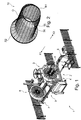
- the reinforcing cage 10 for a reinforcing tube is composed of longitudinal wires 34 and transverse wires 35.
- the reinforcement cage can have three different main geometries in cross-section perpendicular to a longitudinal axis.
- a first main geometry R1 is circular with a first radius
- a second main geometry O is oval
- a third main geometry R2 is again circular with a second radius which is larger in relation to the first radius of the main geometry R1 ( FIG. 2 ).
- the device 2 is designed to move adjusting elements of the machine 1 in such a way that the reinforcing cage 10, as in FIG FIG. 2 can be produced shown.
- the Sp Gillschieber 11 and the mold slide 12 for example, as in the FIGS. 5, 7 . 9 and 11 represented, parallel to a longitudinal axis L of the expansion shaft 5 on the expansion shaft 5 method.
- adjusting operations of the expansion slide 11 and of the mold slide 12 and thus of the adjusting elements 15a, 15b, 15c for making the reinforcement cage 10 on the machine 1:
- a starting position FIG. 5
- the mold slide 12 In a starting position ( FIG. 5 ) is the mold slide 12 so moved up to the Sp Schwarzschieber 11, via the actuator 30 so that the mold slide 12 advantageously clamps the guide elements 24a, 24b, 24c between its first stop member 23 and the first stop surface 22 of the Sp Schwarzschiebers.
- the guide elements 24a, 24b, 24c have in the starting position all a same starting position S along a longitudinal axis L of the spreader shaft 5 on the spreader shaft 5.
- the distance between the mold slide 12 and the expansion slide 11 is changed via the actuator 30.
- the expansion slide 11 changes its position relative to the starting position S. along the longitudinal axis L of the expansion shaft. 5
- the mold slide 12 is pushed away in the direction X1 parallel to the longitudinal axis L by the expansion slide 11 by the actuator 30.
- the mold slide 12 strikes a driving face 31a, 32a of the shaping elements 27a, 27b in this movement after a shorter or longer travel distance with its second stop element 32 formed opposite the first stop element 23.
- the mold slide 12 moves the chains 13a, 13b, 13c differently as it moves in the direction X1.
- the chain 13a is moved along the full movement length of the mold slide 12 in the direction X1, since the mold slide 12 is already in the starting position with its second stop member 32 abuts the driving surface 31a. Accordingly, the actuator 15a changes its position along the spoke 14a toward a larger radius.
- the chain 15b is moved very short compared to the chain 15a. Accordingly, the radius of the control element 15b increases slightly.
- the chain 15c is not moved at all, since the mold slide 12 with its second stop member 32 meets no resistance or attack. Accordingly, the radius of the actuating element 15c likewise does not change ( FIG. 8 ). It would also be conceivable that the device 2 is designed turned over, so that the adjusting elements 15a, 15b would be moved in the opposite direction and would reduce the radius of the adjusting elements 15a, 15b.
- the mold slide 12 can be moved until the Wegbeskyr 26 abuts with its stop against the second stop surface 25 of the Speizschiebers 11. As a result, a maximum travel of the mold slide 12 is limited relative to the Sp Schwarzschieber 11. As a result, a maximum difference of a radius of an actuating element is set to a further actuator.
- the expansion slide 11 with its first stop face 22 only at the end of its movement reaches the driving face 19a of the guide element 24a, with which the chain 13a remains unmoved in this case ( FIG. 9, 11 ).
- the actuator 15a remains along the spoke 14a in this movement of the Sp Schwarzschiebers 11 on its position on the spoke 14a and the other two adjusting elements 15b, 15c are moved to a position with the same radius as the actuator 15a on the spokes 14b, 14c.
- the circular geometry R2 is realized with a larger radius ( FIG. 10 ).
- the distance between the expansion slide 11 and the mold slide 12 is held by the actuator 30, for example, so that the mold slide 12 maintains a fixed, identical position relative to the expansion slide 11.
- the Sp Schwarzschieber 11 for example driven by the expansion shaft 5 in the direction X2 parallel to the longitudinal axis L of the expansion shaft 5 is moved back so that the guide elements 24a, 24b, 24c are again at the height of the starting position S and the adjusting elements thus also back to their original position on the spokes 14a, 14b, 14c are located.
Description
Die Erfindung betrifft eine Vorrichtung zum Herstellen von Bewehrungen, insbesondere von Bewehrungskörben für Betonrohre mit Glockenmuffe, gemäß dem Oberbegriff des Anspruchs 1 (siehe z.B.
Vorrichtungen zum Herstellen von Bewehrungen der einleitend bezeichneten Art sind bereits bekannt.Devices for producing reinforcements of the type described in the introduction are already known.
Eine bekannte Vorrichtung ist als Spreizvorrichtung ausgebildet, die mehrere relativ zueinander in Achsrichtung verstellbare Verstellstangen aufweist, an denen je eine radial verstellbare Führung zur Verstellung von Längsstäben der Bewehrung angelenkt ist. Die Verstellstangen wiederum wirken mit einer Verstellplatte zusammen, die einen Stellweg der Verstellstangen aufgrund von Anschlägen an der Verstellstange begrenzen.A known device is designed as a spreading device having a plurality of adjustable relative to each other in the axial adjustment rods, on each of which a radially adjustable guide for the adjustment of longitudinal bars of the reinforcement is articulated. The adjusting rods in turn cooperate with an adjusting plate, which limit a travel of the adjusting rods due to stops on the adjusting rod.
Durch passende Anordnung der Anschläge an den Verstellstangen und einer Verstellung der Verstellstangen und damit einer Verstellung von Längsstäben einer Bewehrung ist es möglich, eine Form der Bewehrung zu verändern.By suitable arrangement of the stops on the adjusting rods and an adjustment of the adjusting rods and thus an adjustment of longitudinal bars of a reinforcement, it is possible to change a shape of the reinforcement.
Der Erfindung liegt die Aufgabe zu Grunde, eine alternative Vorrichtung zur Herstellung von Bewehrungen, insbesondere von Bewehrungskörben für Betonrohre mit Glockenmuffe, bereitzustellen.The object of the invention is to provide an alternative device for producing reinforcements, in particular reinforcing baskets for concrete pipes with a bell socket.
Diese Aufgabe wird durch die Merkmale des Anspruchs 1 gelöst.This object is solved by the features of claim 1.
In den abhängigen Ansprüchen sind vorteilhafte und zweckmäßige Ausführungsformen der Erfindung angegeben.In the dependent claims advantageous and expedient embodiments of the invention are given.
Die Erfindung geht von einer Vorrichtung zur Herstellung von Bewehrungen, insbesondere von Bewehrungskörben für Betonrohre mit Glockenmuffe, aus, mit einer Spreizvorrichtung, die einen einzigen Spreizschieber aufweist, wobei der Spreizschieber dazu ausgebildet ist, eine radiale Position eines Stellelements für einen Längsdraht der Bewehrung über ein Übertragungsmittel der Spreizvorrichtung, insbesondere während des Herstellungsprozess der Bewehrung, zu verändern.The invention relates to a device for the production of reinforcements, in particular of reinforcing baskets for concrete pipes with bell sleeve, with a spreading device which has a single Spreizschieber, wherein the Spreizschieber is adapted to a radial position of a control element for a longitudinal wire of the reinforcement over a Transfer means of the spreading, in particular during the manufacturing process of the reinforcement to change.
Die Übertragungsmittel der Spreizvorrichtung sind beispielsweise als eine Antriebskette und/oder als eine Antriebsstange ausgeformt. Weiterhin weist die Spreizvorrichtung einen Formschieber auf, wobei zur Bewegung des Formschiebers ein Stellantrieb vorgesehen ist. Der wesentliche Aspekt der Erfindung ist nun darin zu sehen, dass für eine lineare Bewegung des Formschiebers gegenüber dem Spreizschieber der Stellantrieb sich am Spreizschieber abstützt.The transmission means of the spreading device are formed for example as a drive chain and / or as a drive rod. Furthermore, the spreading device on a mold slide, wherein an actuator is provided for movement of the mold slide. The essential aspect of the invention is now to be seen in the fact that for a linear movement of the mold slide with respect to the Spreizschieber the actuator is supported on Spreizschieber.
Vorteilhafterweise ist der Formschieber derart ausgestaltet, dass durch den Formschieber die radiale Position eines zugeordneten Stellelements für einen Längsdraht der Bewehrung über ein Übertragungsmittel der Spreizvorrichtung veränderbar ist, insbesondere während des Herstellungsprozess der Bewehrung.Advantageously, the mold slide is designed such that the radial position of an associated adjusting element for a longitudinal wire of the reinforcement via a transfer means of the spreading device is variable by the mold slide, in particular during the manufacturing process of the reinforcement.
Hierdurch ist eine Geometrieänderung der Bewehrung, insbesondere des Bewehrungskorbs, realisierbar, vorteilhaft eine Geometrieänderung eines Querschnitts der Bewehrung z.B. von rund auf oval oder umgekehrt.As a result, a change in geometry of the reinforcement, in particular of the reinforcing cage, can be realized, advantageously a change in geometry of a cross section of the reinforcement, e.g. from round to oval or vice versa.
Der Spreizschieber und/oder der Formschieber ist beispielsweise dazu ausgebildet, eine radiale Position eines zugeordneten Stellelements entlang einer Speiche eines Spreizrads für einen Längsdraht der Bewehrung zu verändern. Vorteilhafterweise wird der Spreizschieber über einen ersten Stellantrieb und der Formschieber über einen zweiten Stellantrieb bewegt.The expansion slide and / or the mold slide is designed, for example, to change a radial position of an associated actuating element along a spoke of a spreader wheel for a longitudinal wire of the reinforcement. Advantageously, the expansion slide is moved via a first actuator and the mold slide via a second actuator.
Ein Spreizrad, beispielsweise ein Hauptrad und/oder ein Vorschubrad, umfasst z.B. zwischen 4 und 48 Speichen, zwischen 8 und 40 Speichen, zwischen 12 und 36 Speichen, zwischen 16 und 32 Speichen oder zwischen 20 und 28 Speichen, insbesondere 24 Speichen.A spreader wheel, for example a main wheel and / or a feed wheel, comprises e.g. between 4 and 48 spokes, between 8 and 40 spokes, between 12 and 36 spokes, between 16 and 32 spokes or between 20 and 28 spokes, especially 24 spokes.
Beispielsweise sind der Spreizschieber und der Formschieber entlang der Übertragungsmittel zum Bewegen des gleichen Stellelements ausgebildet, insbesondere über ein gleiches Übertragungsmittel. Beispielsweise sind der Spreizschieber und der Formschieber mit den Übertragungsmitteln fest, insbesondere positionsfest verbunden.For example, the Spreizschieber and the mold slide along the transmission means for moving the same adjusting element are formed, in particular via a same transmission means. For example, the Spreizschieber and the mold slide with the transmission means are fixed, in particular connected in a fixed position.
Vorteilhafterweise ist der Formschieber relativ beweglich zum Spreizschieber am Spreizschieber, insbesondere auf dem Spreizschieber ausgebildet. Bevorzugterweise bildet ein Formschieber mit dem Spreizschieber eine Stelleinheit für ein Stellelement bzw. mit einem Übertragungsmittel. Beispielsweise sind an einer Vorrichtung mehrere Stelleinheiten vorhanden, insbesondere ist für jedes Stellelement jeder Speiche des Spreizrads eine Stelleinheit und/oder ein Formschieber vorgesehen.Advantageously, the mold slide is relatively movable to the Spreizschieber on Spreizschieber, in particular formed on the Spreizschieber. Preferably, a mold slide forms an actuating unit with the expansion slide Control element or with a transmission means. For example, a plurality of actuators are present on a device, in particular, an actuating unit and / or a mold slide is provided for each actuator each spoke of the spreader.
Bevorzugterweise ist die Vorrichtung, insbesondere die Stelleinheit derart ausgebildet, dass der Spreizschieber und der Formschieber hintereinander in Reihe geschaltet sind.Preferably, the device, in particular the adjusting unit is designed such that the expansion slide and the mold slide are connected in series one behind the other.
Vorteilhafterweise ist der Stellantrieb als Hydraulikzylinder, als Pneumatikzylinder, als Elektromotor und/oder als Spindelantrieb ausgebildet. Insbesondere ist eine Bewegung eines Formschiebers durch den Stellantrieb entkoppelt von einer durch die Spreizwelle angetriebenen Bewegung des Spreizschiebers und/oder des Formschiebers.Advantageously, the actuator is designed as a hydraulic cylinder, as a pneumatic cylinder, as an electric motor and / or as a spindle drive. In particular, a movement of a mold slide by the actuator is decoupled from a movement of the expansion slide and / or the mold slide driven by the expansion shaft.
Ein weiterer vorteilhafter Aspekt der Vorrichtung ist, dass die Vorrichtung mehrere unabhängig voneinander positionierbare Formschieber aufweist.Another advantageous aspect of the device is that the device has a plurality of independently positionable mold slide.
Hierdurch ist eine beliebige Geometrie des Querschnitts der Bewehrung realisierbar. So kann die Vorrichtung durch die unabhängig voneinander positionierbaren Formschieber den Querschnitt der Bewehrung rund, oval, rechteckig, quadratisch oder vieleckig ausbilden.As a result, any geometry of the cross section of the reinforcement can be realized. Thus, the device can form the cross-section of the reinforcement round, oval, rectangular, square or polygonal by the independently positionable mold slide.
Bevorzugterweise sind die Formschieber unabhängig voneinander relativ zum Spreizschieber bewegbar. Beispielsweise weist jeder Formschieber einen eigenen Stellantrieb auf. Denkbar ist auch, dass alle Formschieber miteinander gekoppelt sind und/oder ein einziger Formschieber vorhanden ist. Vorteilhaft ist auch, dass alle Formschieber durch einen einzigen Stellantrieb relativ zum Spreizschieber bewegbar sind. Vorteilhafterweise ist ein Formschieber derart an der Vorrichtung ausgebildet, dass durch Veränderung einer Position des Formschiebers relativ zum Spreizschieber eine radiale Position des zugeordneten Stellelements entlang einer Speiche relativ zu einer radialen Position eines weiteren Stellelements entlang einer weiteren Speiche insbesondere während des Herstellungsprozesses der Bewehrung veränderbar ist.Preferably, the mold slides are independently movable relative to the expansion slide. For example, each mold slide has its own actuator. It is also conceivable that all mold slides are coupled together and / or a single mold slide is present. It is also advantageous that all mold slides are movable by a single actuator relative to the expansion slide. Advantageously, a mold slide is formed on the device such that by changing a position of the mold slide relative to the expansion slide a radial Position of the associated actuating element along a spoke relative to a radial position of a further actuating element along a further spoke, in particular during the manufacturing process of the reinforcement is changeable.
Ein weiterer vorteilhafter Gedanke der Erfindung ist, dass die Spreizvorrichtung mehrere Formschieber aufweist, wobei die Übertragungsmittel der Spreizvorrichtung mehrere Anschlagelemente aufweisen, wobei die Spreizvorrichtung ein Anschlagelement in Form eines Formgebers umfasst, wobei der Formgeber einen Mitnehmer für ein erstes Anschlagorgan eines Formschiebers bildet, und wobei für insbesondere jeden Formschieber ein Formgeber an den Übertragungsmitteln vorhanden ist.Another advantageous idea of the invention is that the spreading device comprises a plurality of mold slides, wherein the transmission means of the spreading device comprises a plurality of stop elements, wherein the spreading device comprises a stop element in the form of a former, wherein the former forms a driver for a first stop member of a mold slide, and wherein in particular for each mold slide a former is present on the transmission means.
Dadurch ist beispielsweise eine maximale Differenz einer radialen Position eines Stellelements zu einer weiteren radialen Position eines weiteren Stellelements vorgebbar. Hierbei wird unter Differenz der radialen Positionen ein Unterschied eines Abstandes eines Stellelements von einer Rotationsachse der Spreizwelle zu einem weiteren Abstand eines weiteren Stellelements zur Rotationsachse der Spreizwelle verstanden. Hierdurch ist ein maximaler Abstand eines größten Abstands zu einer Rotationsachse des Spreizrads zu einem kleinsten Abstand zu einer Rotationsachse des Spreizrads eines Querschnitts der Bewehrung während einer Herstellung vorgebbar.As a result, for example, a maximum difference of a radial position of an actuating element can be predetermined to a further radial position of a further adjusting element. Here, by difference of the radial positions, a difference of a distance of an actuating element from a rotation axis of the expansion shaft to a further distance of a further adjusting element to the axis of rotation of the expansion shaft is understood. In this way, a maximum distance of a greatest distance to a rotation axis of the spreader wheel at a smallest distance to a rotation axis of the spreader wheel of a cross section of the reinforcement during production can be predetermined.
Denkbar ist, dass der Stellantrieb den Formgeber umfasst. Vorteilhafterweise ist der Formgeber positionsfest an den Übertragungsmitteln ausgebildet.It is conceivable that the actuator comprises the former. Advantageously, the former is positionally fixed to the transmission means.
Ein weiterer vorteilhafter Vorschlag der Erfindung ist, dass alle Übertragungsmittel bezüglich dem Spreizschieber beweglich geführt sind.Another advantageous proposal of the invention is that all transmission means are movably guided with respect to the expansion slide.
Vorteilhafterweise koppelt der Spreizschieber und/oder der Formschieber ausschließlich über ein Anschlagelement mit den Übertragungsmitteln. Insbesondere ist der Spreizschieber und/oder der Formschieber relativ zu den Übertragungsmittel beweglich positionierbar. Beispielsweise ist ein Übertragungsmittel am Spreizschieber und/oder an einem Formschieber beweglich geführt. Hierdurch koppeln der Spreizschieber und/oder der Formschieber z.B. ausschließlich bei einem Stellvorgang des zugeordneten Stellelements mit einem Übertragungsmittel und/oder mit einem Anschlagelement eines Übertragungsmittels.Advantageously, the expansion slide and / or the coupled Form slide exclusively via a stop element with the transmission means. In particular, the Spreizschieber and / or the mold slide is movable relative to the transfer means positionable. For example, a transmission means is movably guided on the expansion slide and / or on a mold slide. As a result, the expansion slide and / or the mold slide, for example, couple exclusively with a setting process of the associated actuating element with a transmission means and / or with a stop element of a transmission means.
Eine weitere bevorzugte Idee der Erfindung ist, dass die Spreizvorrichtung einen Formschieber aufweist, wobei der Spreizschieber an den Übertragungsmitteln beweglich geführt ist, wobei ein Anschlagelement an den Übertragungsmitteln fixiert ist, welches zwischen dem Spreizschieber und einem Formschieber einklemmbar ist.Another preferred idea of the invention is that the spreading device has a mold slide, wherein the expansion slide is movably guided on the transmission means, wherein a stop element is fixed to the transmission means, which can be clamped between the expansion slide and a mold slide.
Vorteilhafterweise ist das einklemmbare Anschlagelement als Führungselement ausgestaltet. Insbesondere sind mindestens zwei Führungselemente vorgesehen, wobei jedes Führungselement jeweils zwischen dem Spreizschieber und einem Formschieber einklemmbar ist. Dadurch bildet das Führungselement einen Mitnehmer für eine erste Anschlagfläche des Spreizelements und für ein zweites Anschlagorgan des Formschiebers. Das zweite Anschlagorgan des Formschiebers ist bevorzugterweise dem ersten Anschlagorgan gegenüberliegend angeordnet.Advantageously, the einklemmbare stop element is designed as a guide element. In particular, at least two guide elements are provided, each guide element can be clamped in each case between the Spreizschieber and a mold slide. As a result, the guide element forms a driver for a first stop surface of the expansion element and for a second stop member of the mold slide. The second stop member of the mold slide is preferably arranged opposite the first stop member.
Beispielsweise ist ein Anschlagelement positionsfest an den Übertragungsmitteln vorhanden. Insbesondere koppeln der Spreizschieber und ein Formschieber über ein Anschlagelement mit den Übertragungsmitteln. Vorteilhafterweise koppelt ein einziger Formschieber über ein einziges Anschlagelement mit einem oder mehreren Übertragungsmitteln, bevorzugt mit einer Antriebskette oder einer Antriebsstange.For example, a stop element positionally fixed to the transmission means available. In particular, the expansion slide and a mold slide couple via a stop element with the transmission means. Advantageously, a single mold slide couples via a single stop element with one or more transmission means, preferably with a drive chain or a drive rod.
Denkbar ist auch, dass ein Stellantrieb ein Führungselement umfasst. Beispielsweise ist jeweils eine zweite Zylinderkammer eines Zylinders des Stellantriebs derart ausgestaltet, dass der Zylinder, insbesondere die Zylinderkammer das Führungselement und/oder den Mitnehmer bildet.It is also conceivable that an actuator is a guide element includes. For example, in each case a second cylinder chamber of a cylinder of the actuator is designed such that the cylinder, in particular the cylinder chamber forms the guide element and / or the driver.
Vorteilhaft erweist sich auch, dass die Spreizvorrichtung ein Anschlagelement in Form eines Wegbegrenzers aufweist, wobei der Wegbegrenzer einen Mitnehmer für eine zweite Anschlagfläche des Spreizschiebers bildet, wobei der Wegbegrenzer einen maximalen Abstand zwischen einem ersten Anschlagorgan des Formschiebers und der zweiten Anschlagfläche des Spreizschiebers vorgibt.Advantageously, it also proves that the spreading device has a stop element in the form of a Wegbegrenzers, the Wegbegrenzer forms a driver for a second stop surface of the Spreizschiebers, the Wegbegrenzer specifies a maximum distance between a first stop member of the mold slide and the second stop surface of the Spreizschiebers.
Der Wegbegrenzer gibt insbesondere einen maximalen Abstand zwischen dem ersten Anschlagorgan des Formschiebers am Formgeber und der zweiten Anschlagfläche des Spreizschiebers vor. Durch diesen Abstand ist eine maximale radiale Positions-Differenz der Stellelemente zueinander vorgegeben. Vorteilhafterweise umfasst die Spreizvorrichtung einen einzigen Wegbegrenzer. Denkbar ist auch, dass ein Stellantrieb einen Wegbegrenzer aufweist.The travel limiter in particular provides a maximum distance between the first stop member of the mold slide on the former and the second stop surface of the expansion slide. By this distance, a maximum radial position difference of the adjusting elements is predetermined to each other. Advantageously, the spreading device comprises a single travel limiter. It is also conceivable that an actuator has a Wegbegrenzer.
Bevorzugterweise sind die beiden Anschlagflächen des Spreizelements sich gegenüberliegend am Spreizelement vorhanden.Preferably, the two abutment surfaces of the expansion element are present opposite to the expansion element.
Alternativ ist der Stellantrieb als ein doppeltwirkender Zylinder ausgebildet. Der doppeltwirkende Zylinder ist z.B. als Hydraulikzylinder oder als Pneumatikzylinder ausgestaltet. Vorstellbar ist, dass der doppeltwirkende Zylinder den Formgeber umfasst. Beispielsweise ist eine Hublänge einer ersten Zylinderkammer der Zylinder z.B. verschieden zueinander ausgestaltet, dass durch die Hublängen der Zylinder eine maximale Differenz einer radialen Position eines Stellelements zu einer weiteren radialen Position eines weiteren Stellelements vorgebbar ist.Alternatively, the actuator is designed as a double-acting cylinder. The double-acting cylinder is e.g. designed as a hydraulic cylinder or as a pneumatic cylinder. It is conceivable that the double-acting cylinder comprises the former. For example, a stroke length of a first cylinder chamber of the cylinders is e.g. configured differently to each other, that by the stroke lengths of the cylinder, a maximum difference of a radial position of an actuating element to a further radial position of a further adjusting element can be predetermined.
Überdies von Vorteil ist, dass der Spreizschieber und ein Formschieber durch eine Spreizwelle der Vorrichtung insbesondere getrennt voneinander angetrieben werden.Moreover, it is advantageous that the expansion slide and a Form slide are driven by a Spreizwelle the device in particular separately from each other.
Vorteilhafterweise kann die Spreizwelle den Stellantrieb bilden. Der Spreizschieber und der Formschieber können derart an der Spreizwelle vorhanden sein, dass die Spreizwelle den Formschieber und den Spreizschieber getrennt voneinander bewegen kann.Advantageously, the expansion shaft can form the actuator. The expansion slide and the mold slide can be present on the expansion shaft in such a way that the expansion shaft can move the mold slide and the expansion slide separately from one another.
Weiter wird vorgeschlagen, dass eine Position eines Anschlagelements entlang der Übertragungsmittel veränderbar ist.It is further proposed that a position of a stop element along the transfer means is changeable.
Beispielsweise ist eine Position eines Formgebers, eines Wegbegrenzers und/oder eines Führungselements insbesondere entlang einer Antriebskette veränderbar. Vorteilhafterweise ist ein Abstand zwischen jeweils einem Formgeber und einem Führungselement entlang der Übertragungsmittel veränderbar. Bevorzugterweise ist eine Distanz zwischen jeweils einem Führungselement und einem Wegbegrenzer entlang der Übertragungsmittel konstant und unveränderbar.For example, a position of a former, a Wegbegrenzers and / or a guide element is variable, in particular along a drive chain. Advantageously, a distance between each of a former and a guide element along the transfer means is changeable. Preferably, a distance between in each case a guide element and a Wegbegrenzer along the transmission means is constant and unchangeable.
Beispielsweise ist ein erster Abstand eines ersten Formgebers zu einem ersten Führungselement entlang einer ersten Antriebskette ungleich zu einem zweiten Abstand eines zweiten Formgebers zu einem zweiten Führungselement entlang einer zweiten Antriebskette. Hierdurch ist ein Formwechsel des Bewehrungskorbs z.B. von rund auf oval oder umgekehrt im montierten Zustand der Vorrichtung an der Maschine realisierbar. Denkbar ist allerdings auch, dass alle Abstände zwischen den Formgebern und den Führungselementen gleich sind. Dadurch ist eine Größenveränderung der Bewehrungskorbform, z.B. des Bewehrungskorbdurchmessers realisierbar.For example, a first distance of a first former to a first guide element along a first drive chain is not equal to a second distance of a second former to a second guide element along a second drive chain. As a result, a change of shape of the reinforcement cage is e.g. from round to oval or vice versa in the assembled state of the device on the machine feasible. However, it is also conceivable that all distances between the formers and the guide elements are the same. Thereby, a change in size of the reinforcing cage shape, e.g. the reinforcement cage diameter can be realized.
Vorteilhafterweise ist eine Distanz zwischen den Führungselementen und einem Wegbegrenzer gleich. Insbesondere ist eine erste Distanz eines ersten Führungselements zu einem ersten Wegbegrenzer entlang einer ersten Antriebskette gleich einem zweiten Abstand eines zweiten Führungselements zu einem zweiten Wegbegrenzer entlang einer zweiten Antriebskette. Hierdurch ist ein maximaler Abstand einer radialen Position eines ersten Stellelements zu einer radialen Position einen zweiten Stellelements vorgebbar.Advantageously, a distance between the guide elements and a Wegbegrenzer is the same. In particular, a first distance of a first guide element to a first travel limiter along a first drive chain is the same a second distance of a second guide element to a second Wegbegrenzer along a second drive chain. In this way, a maximum distance of a radial position of a first actuating element to a radial position of a second actuating element can be predetermined.
Ein Ausführungsbeispiel wird anhand der nachstehenden schematischen Zeichnungen unter Angabe weiterer Einzelheiten und Vorteile näher erläutert.An embodiment will be explained in more detail with reference to the following schematic drawings, indicating further details and advantages.
Es zeigen:
- Figur 1
- eine perspektivische Ansicht von seitlich oben auf eine Maschine zur Herstellung von Bewehrungen mit einer erfindungsgemäßen Vorrichtung,
Figur 2- eine perspektivische Ansicht von seitlich vorne oben auf einen Bewehrungskorb,
Figur 3- eine perspektivische Ansicht von seitlich hinten oben auf die Vorrichtung nach
Figur 1 , Figur 4- eine Draufsicht in vereinfachter Darstellung auf einen Querschnitt, parallel zu einer Längsachse einer Spreizwelle einer Maschine, einer Vorrichtung und
Figuren 5bis 11- eine schematische Darstellung auf einen Querschnitt parallel zur Längsachse der Vorrichtung und senkrecht zur Längsachse der Vorrichtung durch ein Hauptrad der Maschine in unterschiedlichen Funktionspositionen.
- FIG. 1
- a perspective view from the side on top of a machine for producing reinforcements with a device according to the invention,
- FIG. 2
- a perspective view from the front side on top of a reinforcement cage,
- FIG. 3
- a perspective view from the rear side on top of the device according to
FIG. 1 . - FIG. 4
- a plan view in a simplified representation of a cross section, parallel to a longitudinal axis of a spreader shaft of a machine, a device and
- FIGS. 5 to 11
- a schematic representation of a cross section parallel to the longitudinal axis of the device and perpendicular to the longitudinal axis of the device by a main wheel of the machine in different functional positions.
Eine Maschine 1 zur Herstellung von einem Bewehrungskorb 10 umfasst eine erfindungsgemäße Vorrichtung 2, welche im Bereich eines Hauptrads 3 der Maschine 1 am Hauptrad 3 ausgebildet ist. Das Hauptrad 3 ist an einem Hauptrahmen 4, insbesondere positionsfest zum Hauptrahmen 4 befestigt. Des Weiteren umfasst die Maschine 1 eine Spreizwelle 5, einen Spreizbock 6 und einen Vorschubwagen 7 mit einem Vorschubrad 8, welcher auf Führungsschienen 9 linear verfahrbar gelagert ist (
Am Hauptrad 3 ist eine Speiche 14 vorhanden, entlang welcher ein Stellelement 15 in radialer Richtung, senkrecht zu einer Längsachse L der Spreizwelle 5 verschieblich gelagert ist. Des Weiteren ist ein Drahtführungsrohr 16 am Stellelement 15 angeordnet, welches dazu vorgesehen ist, einen Längsdraht 34 des Bewehrungskorbs 10, insbesondere parallel zur Längsachse L an das Stellelement 15 zu führen (
Die Vorrichtung 2 umfasst einen Spreizschieber 11, einen Formschieber 12 und ein Übertragungsmittel in Form einer Kette 13. Die Kette 13 ist beispielsweise als Endloskette ausgebildet, d.h. Enden der Kette 13 sind miteinander verbunden. Die Kette 13 ist über Kettenumlenkungen 17, 18, 19a, 19b beweglich geführt und verbindet das Stellelement 15 mit einer Stelleinheit 20, welche aus dem Formschieber 12 und dem Spreizschieber 11 besteht. Die Kette 13 ist fest mit dem Stellelement 15 verbunden. Aus Übersichtlichkeitsgründen ist in
Die Anschlagelemente sind insbesondere vor einer Produktion eines Bewehrungskorbs 10 auf die entsprechende Geometrie des Bewehrungskorbs 10 einstellbar. Jede Kette 13a, 13b, 13c ist außerdem mit jeweils einem Stellelement 15a, 15b bzw. 15c insbesondere fest gekoppelt (
Die Kette 13a, 13b, 13c besitzt einen stabförmigen Abschnitt 21a, 21b, 21c. Am stabförmigen Abschnitt 21a, 21b, 21c ist die Kette 13a, 13b, 13c beweglich, in einer parallelen Richtung X1 oder X2 zur Längsachse L der Spreizwelle 5 am Spreizschieber 11 und am Formschiebern 12 gelagert. Am stabförmigen Abschnitt 21a, 21b, 21c der Kette 13a, 13b, 13c ist zwischen einer ersten Anschlagfläche 22 des Spreizschiebers 11 und einem ersten Anschlagorgan 23 des Formschiebers 12 ein Führungselement 24a, 24b, 24c positionsfest insbesondere parallel zur Längsachse L der Spreizwelle 5 an den Ketten 13a, 13b, 13c angebracht. Das Führungselement 24a, 24b, 24c ist z.B. als Mitnehmer mit Mitnahmeflächen 28a, 28b, 28c, 29a, 29b, 29c für den Spreizschieber 11 und den Formschieber 12 ausgebildet.The
An einer der ersten Anschlagfläche 22 des Spreizschiebers 11 gegenüber liegenden Seite ist eine zweite Anschlagfläche 25 vorhanden. Am stabförmigen Abschnitt 21a ist außerdem ein Wegbegrenzer 26 positionsfest angebracht, wobei dieser an der, der zweiten Anschlagfläche 25 zugewandten Seite des Spreizschiebers 11 vorhanden ist, so dass die Anschlagflächen 22, 25 des Spreizschiebers 11 zwischen dem Wegbegrenzer 26 und dem Formschieber 12 ausgebildet sind. Vorteilhafterweise ist die Vorrichtung 2 derart ausgebildet, dass eine einzige Kette 13a einen Wegbegrenzer 26 umfasst.At one of the
Außerdem sind an den stabförmigen Abschnitten 21a, 21b Formgeber 27a, 27b positionsfest angeordnet. Die Formgeber 27a, 27b können beispielsweise in ihrer Form unterschiedlich groß ausgebildet sein, insbesondere sind die Formgeber 27a, 27b derart an den stabförmigen Abschnitten 21a, 21b befestigt, dass Mitnahmeflächen 31a, 31b der Formgeber 27a, 27b unterschiedliche Abstände zu den Mitnahmeflächen 28a, 28b der Führungselemente 24a, 24b aufweisen. Sind die Formgeber 27a, 27b verschieblich an den Ketten 13a, 13b vorhanden, können die Formgeber 27a, 27b an ein Mitnahmeelement 36a, 36b der Ketten 13a, 13b anschlagen, wobei die Mitnahmeelemente 36a, 36b in Richtung X1, X2 positionsfest an den Ketten 13a, 13b vorhanden sind.In addition, on the rod-shaped
Der Spreizschieber 11 ist derart gelagert, dass er durch die Spreizwelle 5 in einer Richtung X1 bzw. X2 parallel zur Längsachse L der Spreizwelle 5 verschieblich antreibbar ist. Der Formschieber 12 ist in einer Richtung X1 bzw. X2 parallel zur Längsachse L der Spreizwelle 5 beweglich am Spreizschieber 11 gelagert. Über einen Stellantrieb 30, welcher zwischen dem Spreizschieber 11 und dem Formschieber 12 ausgebildet ist, ist eine Position des Formschiebers 12 relativ zum Spreizschieber 11 veränderbar.The
In den
Der Bewehrungskorb 10 für ein Bewehrungsrohr ist aus Längsdrähten 34 und Querdrähten 35 zusammengesetzt. Der Bewehrungskorb kann z.B. im Querschnitt senkrecht zu einer Längsachse drei unterschiedliche Hauptgeometrien aufweisen. Eine erste Hauptgeometrie R1 ist beispielsweise kreisförmig mit einem ersten Radius, eine zweite Hauptgeometrie O ist oval und eine dritte Hauptgeometrie R2 ist wiederum kreisförmig mit einem zweiten Radius, welcher im Verhältnis zum ersten Radius der Hauptgeometrie R1 größer ist (
Im Folgenden werden Verstellvorgänge des Spreizschiebers 11 und des Formschiebers 12 und damit der Stellelemente 15a, 15b, 15c (
In einer Ausgangsposition (
In a starting position (
Möchte man nun die Geometrie der Bewehrung verändern, bspw. von der kreisförmigen Geometrie R1 auf eine ovale Geometrie O, verändert man den Abstand des Formschiebers 12 zum Spreizschieber 11 über den Stellantrieb 30. Dies bedeutet, der Spreizschieber 11 verändert seine Position relativ zur Startposition S entlang der Längsachse L der Spreizwelle 5 nicht. Der Formschieber 12 hingegen wird in Richtung X1 parallel zur Längsachse L vom Spreizschieber 11 durch den Stellantrieb 30 weggedrückt. Je nach Abstand zu den Formgebern 27a, 27b trifft der Formschieber 12 bei dieser Bewegung nach einer kürzeren oder längeren Wegstrecke mit seiner, dem ersten Anschlagorgan 23 gegenüberliegend ausgebildeten zweiten Anschlagorgan 32 auf eine Mitnahmefläche 31a, 32a der Formgeber 27a, 27b. Hierdurch bewegt der Formschieber 12 die Ketten 13a, 13b, 13c bei seiner Bewegung in Richtung X1 unterschiedlich weit. Im Beispiel (
Der Formschieber 12 kann so weit bewegt werden, bis der Wegbegrenzer 26 mit seinem Anschlag gegen die zweite Anschlagfläche 25 des Speizschiebers 11 stößt. Dadurch ist ein maximaler Verfahrweg des Formschiebers 12 relativ zum Spreizschieber 11 begrenzt. Hierdurch ist auch eine maximale Differenz eines Radius eines Stellelements zu einem weiteren Stellelement vorgegeben.The
Möchte man nun, im Verlauf der Produktion der Bewehrung 10, die Geometrie der Bewehrung 10 auf einen Querschnitt mit einer kreisförmigen Geometrie R2 mit einem größeren Radius verändern, bewegt man den Spreizschieber 11, z.B. angetrieben durch die Spreizwelle 5, parallel zur Längsachse L der Spreizwelle 5 in Richtung X1 auf den Formschieber 12 zu (
Möchte man nun wieder zur kreisförmigen Geometrie R1 mit kleinem Radius zurückkehren, wird der Abstand zwischen dem Spreizschieber 11 und dem Formschieber 12 z.B. durch den Stellantrieb 30 festgehalten, sodass der Formschieber 12 relativ zum Spreizschieber 11 eine feste, gleiche Position beibehält. Anschließend wird der Spreizschieber 11 z.B. angetrieben durch die Spreizwelle 5 in Richtung X2 parallel zur Längsachse L der Spreizwelle 5 zurück gefahren, so dass sich die Führungselemente 24a, 24b, 24c wieder auf Höhe der Startposition S befinden und sich die Stellelemente damit ebenfalls wieder in Ihre Ausgangsposition an den Speichen 14a, 14b, 14c befinden.If one now wishes to return again to the circular geometry R1 with a small radius, the distance between the
- 11
- Maschinemachine
- 22
- Vorrichtungcontraption
- 33
- Hauptradmain wheel
- 44
- Hauptrahmenmain frame
- 55
- Spreizwellespreadshaft
- 66
- SpreizbockSpreizbock
- 77
- Vorschubwagenfeed carriage
- 88th
- Vorschubradfeed gear
- 99
- Führungsschienenguide rails
- 1010
- Bewehrungskorbreinforcing cage
- 1111
- SpreizschieberSpreizschieber
- 1212
- Formschiebershape shifter
- 13, 13a bis 13c13, 13a to 13c
- KetteChain
- 14, 14a bis 14c14, 14a to 14c
- Speichespoke
- 15, 15a bis 15c15, 15a to 15c
- Stellelementactuator
- 1616
- DrahtführungsrohrWire guide tube
- 1717
- Kettenumlenkungchain Reverse
- 1818
- Kettenumlenkungchain Reverse
- 19a, 19b19a, 19b
- Kettenumlenkungchain Reverse
- 2020
- Stelleinheitactuator
- 21a bis 21c21a to 21c
- Abschnittsection
- 2222
- Anschlagorganstop member
- 2323
- Anschlagflächestop surface
- 24a bis 24c24a to 24c
- Führungselementguide element
- 2525
- Anschlagflächestop surface
- 2626
- Wegbegrenzertravel limiters
- 27a, 27b27a, 27b
- Formgebershaper
- 28a, 28b28a, 28b
- Mitnahmeflächedrive surface
- 29a, 29b29a, 29b
- Mitnahmeflächedrive surface
- 3030
- Stellantriebactuator
- 31a, 31b31a, 31b
- Mitnahmeflächedrive surface
- 3232
- Anschlagorganstop member
- 3333
- Anschlagattack
- 3434
- Längsdrahtlongitudinal wire
- 3535
- Querdrahtcross wire
- 36a, 36b36a, 36b
- Mitnahmeelementdriving element
Claims (10)
- Device (2) for producing reinforcements, in particular reinforcement baskets (10) for concrete pipes having bell-shaped ends, comprising an expander device (20), which comprises a single expander slide (11), wherein the expander slide (11) is designed to change a radial position of an adjusting element (15, 15a, 15b, 15c) for a longitudinal wire (34) of the reinforcement (10) via a transmission means (13, 13a, 13b, 13c) of the expander device (20), in particular during the production process of the reinforcement (10),
wherein the expander device (20) comprises a form slide (12), wherein for moving the form slide (12) an actuator (30) is provided, characterised in that for a linear movement of the form slide (12) relative to the expander slide (11) the actuator (30) is supported on the expander slide (11). - Device (2) according to claim 1, characterised in that the device (2) comprises a plurality of form slides (12) which can be positioned independently of one another.
- Device (2) according to claim 1, characterised in that the transmission means (13, 13a, 13b, 13c) of the expander device (20) comprise a plurality of stop elements, wherein the expander device (20) comprises a stop element in the form of a shaper (27a, 27b), wherein the shaper (27a, 27b) forms a driver for a first stop element (22) of a form slide (12), and wherein for each form slide (12) a shaper (27a, 27b) is provided on the transmission means (13, 13a, 13b, 13c).
- Device (2) according to any of claims 1 to 3, characterised in that all of the transmission means (13, 13a, 13b, 13c) are guided movably relative to the expander slide (11).
- Device (2) according to any of claims 1 to 4, characterised in that the expander slide (11) is guided movably on the transmission means (13, 13a, 13b, 13c), wherein a stop element (24a, 24b, 24c) is fixed on the transmission means (13, 13a, 13b, 13c), which can be clamped between the expander slide (11) and a form slide (12).
- Device (2) according to any of the preceding claims, characterised in that the expander device (20) comprises a stop element in the form of a delimiter (26), wherein the delimiter (26) forms a driver (33) for a second stop surface (25) of the expander slide (11), wherein the delimiter (26) determines a maximum distance between a first and/or a second stop element (22, 32) of the form slide (12) and the second stop surface (25) of the expander slide (11).
- Device (2) according to any of the preceding claims, characterised in that the actuator (30) is designed as a double-acting cylinder.
- Device (2) according to any of the preceding claims, characterised in that the expander slide (11) and a form slide (12) are driven, in particular separately from one another, by an expanding shaft (5) of the device (2).
- Device (2) according to any of the preceding claims, characterised in that a position of a stop element (24a, 24b, 24c, 26, 27a, 27b) can be changed along the transmission means (13, 13a, 13b, 13c).
- Machine (1) for producing reinforcements (10) comprising a device (2), according to any of the preceding claims.
Applications Claiming Priority (1)
| Application Number | Priority Date | Filing Date | Title |
|---|---|---|---|
| DE102016108098.5A DE102016108098A1 (en) | 2016-05-02 | 2016-05-02 | Device for producing reinforcements |
Publications (3)
| Publication Number | Publication Date |
|---|---|
| EP3199261A2 EP3199261A2 (en) | 2017-08-02 |
| EP3199261A3 EP3199261A3 (en) | 2017-09-06 |
| EP3199261B1 true EP3199261B1 (en) | 2018-07-11 |
Family
ID=58018094
Family Applications (1)
| Application Number | Title | Priority Date | Filing Date |
|---|---|---|---|
| EP17155416.5A Active EP3199261B1 (en) | 2016-05-02 | 2017-02-09 | Device for producing reinforcements |
Country Status (9)
| Country | Link |
|---|---|
| US (1) | US10710144B2 (en) |
| EP (1) | EP3199261B1 (en) |
| CN (1) | CN109070182B (en) |
| CA (1) | CA3020417C (en) |
| DE (1) | DE102016108098A1 (en) |
| ES (1) | ES2690520T3 (en) |
| RU (1) | RU2716336C1 (en) |
| WO (1) | WO2017190855A1 (en) |
| ZA (1) | ZA201806750B (en) |
Families Citing this family (1)
| Publication number | Priority date | Publication date | Assignee | Title |
|---|---|---|---|---|
| BR112022022186A2 (en) * | 2020-07-02 | 2023-01-17 | Mbk Maschb Gmbh | DEVICE FOR THE PRODUCTION OF A METAL MESH REINFORCEMENT |
Family Cites Families (13)
| Publication number | Priority date | Publication date | Assignee | Title |
|---|---|---|---|---|
| SU435888A1 (en) * | 1972-02-23 | 1974-07-15 | INSTALLATION FOR MANUFACTURING ARMATURE CARPETS | |
| DE2360532A1 (en) * | 1973-12-05 | 1975-06-12 | Georg Pfender | Assembly machine for producing reinforcing cages for concrete tubes - welds wire coils to set of longitudinal bars |
| FR2286681A1 (en) * | 1974-10-03 | 1976-04-30 | Tuyaux Bonna | Concrete reinforcement cage welding fixture - has wire coils through guide plates for welding into cage structure |
| DE2946297C2 (en) * | 1979-11-16 | 1986-08-07 | Mbk Maschinenbau Gmbh, 7964 Kisslegg | Machine for the production of reinforcement bodies for concrete pipes |
| DE3422420A1 (en) * | 1984-06-16 | 1985-12-19 | Mbk Maschinenbau Gmbh, 7964 Kisslegg | MACHINE FOR PRODUCING REINFORCEMENT BODIES FOR CONCRETE PIPES |
| SU1337176A1 (en) * | 1984-08-25 | 1987-09-15 | Молдавский Научно-Исследовательский И Проектно-Конструкторский Институт Строительных Материалов | Automatic line for manufacturing reinforcing cages |
| DE59204507D1 (en) * | 1992-03-07 | 1996-01-11 | Mbk Maschinenbau Gmbh | Machine and method for making reinforcement cages for concrete pipes. |
| DE19814091A1 (en) * | 1998-03-30 | 1999-10-07 | Mbk Maschinenbau Gmbh | Device for the production of reinforcement cages for rectangular pipes made of concrete |
| AUPP758898A0 (en) * | 1998-12-10 | 1999-01-07 | Barden, Wayne | An apparatus for making reinforcing cages for reinforcing concrete |
| DE102004041736A1 (en) * | 2004-08-28 | 2006-03-02 | Ed. Züblin Ag | Manufacturing machine for continuous production of reinforcement cages for e.g. reinforced concrete pipes, masts, stakes, has welding equipment attached to radial adjustment mechanism which is provided with its own drive unit |
| US20080257445A1 (en) * | 2007-04-20 | 2008-10-23 | Claudio Subacchi | Method And System For Manufacture Of A Wire Cage |
| CN201500756U (en) * | 2009-06-01 | 2010-06-09 | 四平市英力建筑机械有限公司 | Adjustable reinforcement cage making machine |
| EP2996827A1 (en) * | 2013-05-17 | 2016-03-23 | Schnell S.p.A. | Apparatus for and method of manufacturing metal cages for conical pillars |
-
2016
- 2016-05-02 DE DE102016108098.5A patent/DE102016108098A1/en not_active Withdrawn
-
2017
- 2017-02-09 CA CA3020417A patent/CA3020417C/en active Active
- 2017-02-09 WO PCT/EP2017/052896 patent/WO2017190855A1/en active Application Filing
- 2017-02-09 ES ES17155416.5T patent/ES2690520T3/en active Active
- 2017-02-09 EP EP17155416.5A patent/EP3199261B1/en active Active
- 2017-02-09 CN CN201780027167.9A patent/CN109070182B/en active Active
- 2017-02-09 RU RU2018141825A patent/RU2716336C1/en active
-
2018
- 2018-10-10 ZA ZA2018/06750A patent/ZA201806750B/en unknown
- 2018-10-24 US US16/169,017 patent/US10710144B2/en active Active
Non-Patent Citations (1)
| Title |
|---|
| None * |
Also Published As
| Publication number | Publication date |
|---|---|
| CA3020417A1 (en) | 2017-11-09 |
| CN109070182A (en) | 2018-12-21 |
| WO2017190855A1 (en) | 2017-11-09 |
| US20190118243A1 (en) | 2019-04-25 |
| ZA201806750B (en) | 2024-02-28 |
| DE102016108098A1 (en) | 2017-11-02 |
| ES2690520T3 (en) | 2018-11-21 |
| BR112018071773A2 (en) | 2019-02-19 |
| US10710144B2 (en) | 2020-07-14 |
| CA3020417C (en) | 2021-01-19 |
| EP3199261A2 (en) | 2017-08-02 |
| RU2716336C1 (en) | 2020-03-11 |
| CN109070182B (en) | 2021-04-30 |
| EP3199261A3 (en) | 2017-09-06 |
Similar Documents
| Publication | Publication Date | Title |
|---|---|---|
| EP2616197B1 (en) | Device and method for producing at least partially closed hollow profiles with rotatable die halves and low cycle time | |
| EP2289643B1 (en) | Device for bending elongated workpieces | |
| CH652947A5 (en) | WIRE BENDING MACHINE. | |
| EP3769923A1 (en) | Guide rail for a motor chain saw and method for producing a guide rail | |
| DE102011053676A1 (en) | Pipe bending machine for shaping sheet metal plates into pipes, has mold segments which are adjustable with shape-defining surface in setting positions in normal plane lying in curve to the pipe axis in accordance with curved contour | |
| EP3199261B1 (en) | Device for producing reinforcements | |
| EP2380674A2 (en) | Expandable bending head | |
| DE4103134C2 (en) | Device for the production of bent sections on a pipe, in particular for the production of a pipe coil | |
| DE102011000845B4 (en) | Method for bending and axial upsetting of a pipe and device for this purpose | |
| DE102009024406A1 (en) | Rotary bending tool has eccentric clamp for bending elongate workpieces, such as pipes, wires, or profile strands, where bending head comprises mandrel rotatable about rotation axis and assigned clamping jaw movable relative to it | |
| DE102014212732A1 (en) | Method and upsetting device for producing offset workpieces, such as shafts or rods | |
| DE102006062242A1 (en) | molding | |
| EP3867038B1 (en) | Corrugator and method for varying a corrugator | |
| EP2205370B1 (en) | Process and apparatus for producing a hollow body, and hollow body | |
| EP2072159B1 (en) | Bending device, especially for tube-shaped components | |
| DE102008048176B4 (en) | Apparatus for pressing a bellows against a sidewall of a green tire in tire manufacture | |
| DE102016007466A1 (en) | Bendable mandrel and associated tool | |
| EP2981373B1 (en) | Method and forming device for a formed wire body and formed wire body | |
| EP3190306B1 (en) | Device and method for manufacturing a bushing | |
| DE102011122144B4 (en) | Device and method for the non-cutting, axially forming formation of an internal toothing on a workpiece | |
| EP4338905A1 (en) | Device and method for processing a material | |
| DE10122763B4 (en) | Device for producing transverse waves on a metal tube | |
| WO2012063125A2 (en) | Tool for machining a workpiece | |
| DE10236822A1 (en) | Method and device for producing a switching drum | |
| DE2305869A1 (en) | MACHINE FOR BENDING PIPES INTO PIPE SLEEVES |
Legal Events
| Date | Code | Title | Description |
|---|---|---|---|
| PUAI | Public reference made under article 153(3) epc to a published international application that has entered the european phase |
Free format text: ORIGINAL CODE: 0009012 |
|
| STAA | Information on the status of an ep patent application or granted ep patent |
Free format text: STATUS: REQUEST FOR EXAMINATION WAS MADE |
|
| 17P | Request for examination filed |
Effective date: 20170209 |
|
| AK | Designated contracting states |
Kind code of ref document: A2 Designated state(s): AL AT BE BG CH CY CZ DE DK EE ES FI FR GB GR HR HU IE IS IT LI LT LU LV MC MK MT NL NO PL PT RO RS SE SI SK SM TR |
|
| AX | Request for extension of the european patent |
Extension state: BA ME |
|
| PUAL | Search report despatched |
Free format text: ORIGINAL CODE: 0009013 |
|
| STAA | Information on the status of an ep patent application or granted ep patent |
Free format text: STATUS: EXAMINATION IS IN PROGRESS |
|
| AK | Designated contracting states |
Kind code of ref document: A3 Designated state(s): AL AT BE BG CH CY CZ DE DK EE ES FI FR GB GR HR HU IE IS IT LI LT LU LV MC MK MT NL NO PL PT RO RS SE SI SK SM TR |
|
| AX | Request for extension of the european patent |
Extension state: BA ME |
|
| RIC1 | Information provided on ipc code assigned before grant |
Ipc: B21F 27/12 20060101AFI20170731BHEP Ipc: B21F 27/10 20060101ALN20170731BHEP |
|
| 17Q | First examination report despatched |
Effective date: 20170822 |
|
| RBV | Designated contracting states (corrected) |
Designated state(s): AL AT BE BG CH CY CZ DE DK EE ES FI FR GB GR HR HU IE IS IT LI LT LU LV MC MK MT NL NO PL PT RO RS SE SI SK SM TR |
|
| RIC1 | Information provided on ipc code assigned before grant |
Ipc: B21F 27/10 20060101ALN20171220BHEP Ipc: B21F 27/12 20060101AFI20171220BHEP |
|
| GRAP | Despatch of communication of intention to grant a patent |
Free format text: ORIGINAL CODE: EPIDOSNIGR1 |
|
| STAA | Information on the status of an ep patent application or granted ep patent |
Free format text: STATUS: GRANT OF PATENT IS INTENDED |
|
| INTG | Intention to grant announced |
Effective date: 20180126 |
|
| GRAS | Grant fee paid |
Free format text: ORIGINAL CODE: EPIDOSNIGR3 |
|
| GRAA | (expected) grant |
Free format text: ORIGINAL CODE: 0009210 |
|
| STAA | Information on the status of an ep patent application or granted ep patent |
Free format text: STATUS: THE PATENT HAS BEEN GRANTED |
|
| AK | Designated contracting states |
Kind code of ref document: B1 Designated state(s): AL AT BE BG CH CY CZ DE DK EE ES FI FR GB GR HR HU IE IS IT LI LT LU LV MC MK MT NL NO PL PT RO RS SE SI SK SM TR |
|
| REG | Reference to a national code |
Ref country code: GB Ref legal event code: FG4D Free format text: NOT ENGLISH |
|
| REG | Reference to a national code |
Ref country code: CH Ref legal event code: EP |
|
| REG | Reference to a national code |
Ref country code: AT Ref legal event code: REF Ref document number: 1016359 Country of ref document: AT Kind code of ref document: T Effective date: 20180715 |
|
| REG | Reference to a national code |
Ref country code: IE Ref legal event code: FG4D Free format text: LANGUAGE OF EP DOCUMENT: GERMAN |
|
| REG | Reference to a national code |
Ref country code: DE Ref legal event code: R096 Ref document number: 502017000068 Country of ref document: DE |
|
| REG | Reference to a national code |
Ref country code: NL Ref legal event code: MP Effective date: 20180711 |
|
| REG | Reference to a national code |
Ref country code: ES Ref legal event code: FG2A Ref document number: 2690520 Country of ref document: ES Kind code of ref document: T3 Effective date: 20181121 |
|
| REG | Reference to a national code |
Ref country code: LT Ref legal event code: MG4D |
|
| PG25 | Lapsed in a contracting state [announced via postgrant information from national office to epo] |
Ref country code: NL Free format text: LAPSE BECAUSE OF FAILURE TO SUBMIT A TRANSLATION OF THE DESCRIPTION OR TO PAY THE FEE WITHIN THE PRESCRIBED TIME-LIMIT Effective date: 20180711 |
|
| PG25 | Lapsed in a contracting state [announced via postgrant information from national office to epo] |
Ref country code: NO Free format text: LAPSE BECAUSE OF FAILURE TO SUBMIT A TRANSLATION OF THE DESCRIPTION OR TO PAY THE FEE WITHIN THE PRESCRIBED TIME-LIMIT Effective date: 20181011 Ref country code: SE Free format text: LAPSE BECAUSE OF FAILURE TO SUBMIT A TRANSLATION OF THE DESCRIPTION OR TO PAY THE FEE WITHIN THE PRESCRIBED TIME-LIMIT Effective date: 20180711 Ref country code: PL Free format text: LAPSE BECAUSE OF FAILURE TO SUBMIT A TRANSLATION OF THE DESCRIPTION OR TO PAY THE FEE WITHIN THE PRESCRIBED TIME-LIMIT Effective date: 20180711 Ref country code: IS Free format text: LAPSE BECAUSE OF FAILURE TO SUBMIT A TRANSLATION OF THE DESCRIPTION OR TO PAY THE FEE WITHIN THE PRESCRIBED TIME-LIMIT Effective date: 20181111 Ref country code: RS Free format text: LAPSE BECAUSE OF FAILURE TO SUBMIT A TRANSLATION OF THE DESCRIPTION OR TO PAY THE FEE WITHIN THE PRESCRIBED TIME-LIMIT Effective date: 20180711 Ref country code: BG Free format text: LAPSE BECAUSE OF FAILURE TO SUBMIT A TRANSLATION OF THE DESCRIPTION OR TO PAY THE FEE WITHIN THE PRESCRIBED TIME-LIMIT Effective date: 20181011 Ref country code: LT Free format text: LAPSE BECAUSE OF FAILURE TO SUBMIT A TRANSLATION OF THE DESCRIPTION OR TO PAY THE FEE WITHIN THE PRESCRIBED TIME-LIMIT Effective date: 20180711 Ref country code: FI Free format text: LAPSE BECAUSE OF FAILURE TO SUBMIT A TRANSLATION OF THE DESCRIPTION OR TO PAY THE FEE WITHIN THE PRESCRIBED TIME-LIMIT Effective date: 20180711 |
|
| PG25 | Lapsed in a contracting state [announced via postgrant information from national office to epo] |
Ref country code: AL Free format text: LAPSE BECAUSE OF FAILURE TO SUBMIT A TRANSLATION OF THE DESCRIPTION OR TO PAY THE FEE WITHIN THE PRESCRIBED TIME-LIMIT Effective date: 20180711 Ref country code: HR Free format text: LAPSE BECAUSE OF FAILURE TO SUBMIT A TRANSLATION OF THE DESCRIPTION OR TO PAY THE FEE WITHIN THE PRESCRIBED TIME-LIMIT Effective date: 20180711 Ref country code: LV Free format text: LAPSE BECAUSE OF FAILURE TO SUBMIT A TRANSLATION OF THE DESCRIPTION OR TO PAY THE FEE WITHIN THE PRESCRIBED TIME-LIMIT Effective date: 20180711 |
|
| REG | Reference to a national code |
Ref country code: GR Ref legal event code: EP Ref document number: 20180402766 Country of ref document: GR Effective date: 20190225 |
|
| REG | Reference to a national code |
Ref country code: DE Ref legal event code: R097 Ref document number: 502017000068 Country of ref document: DE |
|
| PG25 | Lapsed in a contracting state [announced via postgrant information from national office to epo] |
Ref country code: RO Free format text: LAPSE BECAUSE OF FAILURE TO SUBMIT A TRANSLATION OF THE DESCRIPTION OR TO PAY THE FEE WITHIN THE PRESCRIBED TIME-LIMIT Effective date: 20180711 Ref country code: CZ Free format text: LAPSE BECAUSE OF FAILURE TO SUBMIT A TRANSLATION OF THE DESCRIPTION OR TO PAY THE FEE WITHIN THE PRESCRIBED TIME-LIMIT Effective date: 20180711 Ref country code: EE Free format text: LAPSE BECAUSE OF FAILURE TO SUBMIT A TRANSLATION OF THE DESCRIPTION OR TO PAY THE FEE WITHIN THE PRESCRIBED TIME-LIMIT Effective date: 20180711 |
|
| PLBE | No opposition filed within time limit |
Free format text: ORIGINAL CODE: 0009261 |
|
| STAA | Information on the status of an ep patent application or granted ep patent |
Free format text: STATUS: NO OPPOSITION FILED WITHIN TIME LIMIT |
|
| PG25 | Lapsed in a contracting state [announced via postgrant information from national office to epo] |
Ref country code: SM Free format text: LAPSE BECAUSE OF FAILURE TO SUBMIT A TRANSLATION OF THE DESCRIPTION OR TO PAY THE FEE WITHIN THE PRESCRIBED TIME-LIMIT Effective date: 20180711 Ref country code: DK Free format text: LAPSE BECAUSE OF FAILURE TO SUBMIT A TRANSLATION OF THE DESCRIPTION OR TO PAY THE FEE WITHIN THE PRESCRIBED TIME-LIMIT Effective date: 20180711 Ref country code: SK Free format text: LAPSE BECAUSE OF FAILURE TO SUBMIT A TRANSLATION OF THE DESCRIPTION OR TO PAY THE FEE WITHIN THE PRESCRIBED TIME-LIMIT Effective date: 20180711 |
|
| 26N | No opposition filed |
Effective date: 20190412 |
|
| PG25 | Lapsed in a contracting state [announced via postgrant information from national office to epo] |
Ref country code: SI Free format text: LAPSE BECAUSE OF FAILURE TO SUBMIT A TRANSLATION OF THE DESCRIPTION OR TO PAY THE FEE WITHIN THE PRESCRIBED TIME-LIMIT Effective date: 20180711 |
|
| PG25 | Lapsed in a contracting state [announced via postgrant information from national office to epo] |
Ref country code: LU Free format text: LAPSE BECAUSE OF NON-PAYMENT OF DUE FEES Effective date: 20190209 Ref country code: MC Free format text: LAPSE BECAUSE OF FAILURE TO SUBMIT A TRANSLATION OF THE DESCRIPTION OR TO PAY THE FEE WITHIN THE PRESCRIBED TIME-LIMIT Effective date: 20180711 |
|
| REG | Reference to a national code |
Ref country code: BE Ref legal event code: MM Effective date: 20190228 |
|
| REG | Reference to a national code |
Ref country code: IE Ref legal event code: MM4A |
|
| PG25 | Lapsed in a contracting state [announced via postgrant information from national office to epo] |
Ref country code: IE Free format text: LAPSE BECAUSE OF NON-PAYMENT OF DUE FEES Effective date: 20190209 |
|
| PG25 | Lapsed in a contracting state [announced via postgrant information from national office to epo] |
Ref country code: FR Free format text: LAPSE BECAUSE OF NON-PAYMENT OF DUE FEES Effective date: 20190228 Ref country code: BE Free format text: LAPSE BECAUSE OF NON-PAYMENT OF DUE FEES Effective date: 20190228 |
|
| PG25 | Lapsed in a contracting state [announced via postgrant information from national office to epo] |
Ref country code: TR Free format text: LAPSE BECAUSE OF FAILURE TO SUBMIT A TRANSLATION OF THE DESCRIPTION OR TO PAY THE FEE WITHIN THE PRESCRIBED TIME-LIMIT Effective date: 20180711 |
|
| PG25 | Lapsed in a contracting state [announced via postgrant information from national office to epo] |
Ref country code: MT Free format text: LAPSE BECAUSE OF FAILURE TO SUBMIT A TRANSLATION OF THE DESCRIPTION OR TO PAY THE FEE WITHIN THE PRESCRIBED TIME-LIMIT Effective date: 20180711 Ref country code: PT Free format text: LAPSE BECAUSE OF FAILURE TO SUBMIT A TRANSLATION OF THE DESCRIPTION OR TO PAY THE FEE WITHIN THE PRESCRIBED TIME-LIMIT Effective date: 20181111 |
|
| REG | Reference to a national code |
Ref country code: CH Ref legal event code: PL |
|
| PG25 | Lapsed in a contracting state [announced via postgrant information from national office to epo] |
Ref country code: CH Free format text: LAPSE BECAUSE OF NON-PAYMENT OF DUE FEES Effective date: 20200229 Ref country code: LI Free format text: LAPSE BECAUSE OF NON-PAYMENT OF DUE FEES Effective date: 20200229 |
|
| PG25 | Lapsed in a contracting state [announced via postgrant information from national office to epo] |
Ref country code: CY Free format text: LAPSE BECAUSE OF FAILURE TO SUBMIT A TRANSLATION OF THE DESCRIPTION OR TO PAY THE FEE WITHIN THE PRESCRIBED TIME-LIMIT Effective date: 20180711 |
|
| PG25 | Lapsed in a contracting state [announced via postgrant information from national office to epo] |
Ref country code: HU Free format text: LAPSE BECAUSE OF FAILURE TO SUBMIT A TRANSLATION OF THE DESCRIPTION OR TO PAY THE FEE WITHIN THE PRESCRIBED TIME-LIMIT; INVALID AB INITIO Effective date: 20170209 |
|
| GBPC | Gb: european patent ceased through non-payment of renewal fee |
Effective date: 20210209 |
|
| PG25 | Lapsed in a contracting state [announced via postgrant information from national office to epo] |
Ref country code: GB Free format text: LAPSE BECAUSE OF NON-PAYMENT OF DUE FEES Effective date: 20210209 |
|
| PG25 | Lapsed in a contracting state [announced via postgrant information from national office to epo] |
Ref country code: MK Free format text: LAPSE BECAUSE OF FAILURE TO SUBMIT A TRANSLATION OF THE DESCRIPTION OR TO PAY THE FEE WITHIN THE PRESCRIBED TIME-LIMIT Effective date: 20180711 |
|
| PGFP | Annual fee paid to national office [announced via postgrant information from national office to epo] |
Ref country code: ES Payment date: 20230317 Year of fee payment: 7 Ref country code: AT Payment date: 20230215 Year of fee payment: 7 |
|
| PGFP | Annual fee paid to national office [announced via postgrant information from national office to epo] |
Ref country code: IT Payment date: 20230228 Year of fee payment: 7 Ref country code: GR Payment date: 20230215 Year of fee payment: 7 Ref country code: DE Payment date: 20230216 Year of fee payment: 7 |
|
| PGFP | Annual fee paid to national office [announced via postgrant information from national office to epo] |
Ref country code: GR Payment date: 20240219 Year of fee payment: 8 |
|
| PGFP | Annual fee paid to national office [announced via postgrant information from national office to epo] |
Ref country code: ES Payment date: 20240319 Year of fee payment: 8 |
|
| PGFP | Annual fee paid to national office [announced via postgrant information from national office to epo] |
Ref country code: AT Payment date: 20240216 Year of fee payment: 8 |