EP3196522A1 - Stellvorrichtung - Google Patents
Stellvorrichtung Download PDFInfo
- Publication number
- EP3196522A1 EP3196522A1 EP17151580.2A EP17151580A EP3196522A1 EP 3196522 A1 EP3196522 A1 EP 3196522A1 EP 17151580 A EP17151580 A EP 17151580A EP 3196522 A1 EP3196522 A1 EP 3196522A1
- Authority
- EP
- European Patent Office
- Prior art keywords
- pipe section
- adjusting device
- actuating element
- corrugated
- corrugated pipe
- Prior art date
- Legal status (The legal status is an assumption and is not a legal conclusion. Google has not performed a legal analysis and makes no representation as to the accuracy of the status listed.)
- Granted
Links
- 230000007704 transition Effects 0.000 claims description 5
- 239000012530 fluid Substances 0.000 description 4
- 230000001419 dependent effect Effects 0.000 description 2
- 238000011161 development Methods 0.000 description 2
- 230000018109 developmental process Effects 0.000 description 2
- 239000000463 material Substances 0.000 description 1
- 239000002184 metal Substances 0.000 description 1
- 230000002093 peripheral effect Effects 0.000 description 1
Images

Classifications
-
- F—MECHANICAL ENGINEERING; LIGHTING; HEATING; WEAPONS; BLASTING
- F16—ENGINEERING ELEMENTS AND UNITS; GENERAL MEASURES FOR PRODUCING AND MAINTAINING EFFECTIVE FUNCTIONING OF MACHINES OR INSTALLATIONS; THERMAL INSULATION IN GENERAL
- F16K—VALVES; TAPS; COCKS; ACTUATING-FLOATS; DEVICES FOR VENTING OR AERATING
- F16K31/00—Actuating devices; Operating means; Releasing devices
- F16K31/44—Mechanical actuating means
- F16K31/445—Mechanical actuating means with exterior sleeve
-
- F—MECHANICAL ENGINEERING; LIGHTING; HEATING; WEAPONS; BLASTING
- F16—ENGINEERING ELEMENTS AND UNITS; GENERAL MEASURES FOR PRODUCING AND MAINTAINING EFFECTIVE FUNCTIONING OF MACHINES OR INSTALLATIONS; THERMAL INSULATION IN GENERAL
- F16K—VALVES; TAPS; COCKS; ACTUATING-FLOATS; DEVICES FOR VENTING OR AERATING
- F16K11/00—Multiple-way valves, e.g. mixing valves; Pipe fittings incorporating such valves
- F16K11/02—Multiple-way valves, e.g. mixing valves; Pipe fittings incorporating such valves with all movable sealing faces moving as one unit
- F16K11/06—Multiple-way valves, e.g. mixing valves; Pipe fittings incorporating such valves with all movable sealing faces moving as one unit comprising only sliding valves, i.e. sliding closure elements
- F16K11/065—Multiple-way valves, e.g. mixing valves; Pipe fittings incorporating such valves with all movable sealing faces moving as one unit comprising only sliding valves, i.e. sliding closure elements with linearly sliding closure members
- F16K11/07—Multiple-way valves, e.g. mixing valves; Pipe fittings incorporating such valves with all movable sealing faces moving as one unit comprising only sliding valves, i.e. sliding closure elements with linearly sliding closure members with cylindrical slides
- F16K11/0716—Multiple-way valves, e.g. mixing valves; Pipe fittings incorporating such valves with all movable sealing faces moving as one unit comprising only sliding valves, i.e. sliding closure elements with linearly sliding closure members with cylindrical slides with fluid passages through the valve member
-
- F—MECHANICAL ENGINEERING; LIGHTING; HEATING; WEAPONS; BLASTING
- F16—ENGINEERING ELEMENTS AND UNITS; GENERAL MEASURES FOR PRODUCING AND MAINTAINING EFFECTIVE FUNCTIONING OF MACHINES OR INSTALLATIONS; THERMAL INSULATION IN GENERAL
- F16K—VALVES; TAPS; COCKS; ACTUATING-FLOATS; DEVICES FOR VENTING OR AERATING
- F16K7/00—Diaphragm valves or cut-off apparatus, e.g. with a member deformed, but not moved bodily, to close the passage ; Pinch valves
- F16K7/02—Diaphragm valves or cut-off apparatus, e.g. with a member deformed, but not moved bodily, to close the passage ; Pinch valves with tubular diaphragm
Definitions
- the invention relates to an adjusting device according to the preamble of patent claim 1.
- An adjusting device of the type mentioned is from the patent document DE 1 289 703 A known.
- This designed as a pneumatic control valve actuator consists of a corrugated pipe section with a wave-shaped pipe wall, an outside of the corrugated pipe section arranged outer actuating element ("guide ring 3") and disposed within the corrugated pipe inner adjusting element ("valve needle 1"), wherein the outer actuating element is formed with the inner actuating element operatively connected ,
- a plurality of corrugated pipe sections are provided, wherein the outer actuating element is arranged between two corrugated pipe sections and, moreover, is formed directly connected to the inner actuating element.
- the invention has for its object to improve an adjusting device of the type mentioned, in particular to simplify.
- At least the outer or the inner actuating element for transmitting a force from the outer to the inner actuating element or vice versa at having the wavy pipe wall adapted contact area.
- the adjusting device according to the invention thus characterized by the fact that for transmitting a force from one to the other adjusting element directly the wave-shaped pipe wall itself via a positive connection with the contact area and not a ring element arranged between two corrugated pipe sections is used.
- a force from one to the other adjusting element directly the wave-shaped pipe wall itself via a positive connection with the contact area and not a ring element arranged between two corrugated pipe sections is used.
- the adjusting device shown in the figures consists of a corrugated pipe section 1 with a wave-shaped pipe wall 1.1, an outside of the corrugated pipe section 1 arranged outer positioning element 2 (in the FIGS. 1 to 4 not shown separately) and arranged within the corrugated pipe section 1 inner adjusting element 3, wherein the outer actuating element 2 is formed operatively connected to the inner actuating element 3.
- Essential for all possible embodiments of the adjusting device according to the invention is that at least the outer or the inner adjusting element 2, 3 for transmitting a force from the outer to the inner actuating element 2, 3 or vice versa has adapted to the wavy pipe wall 1.1 contact area 2.1, 3.1.
- the corrugated pipe section 1 is optionally formed of plastic or metal.
- a smooth cylindrical pipe section 4 is arranged fluid-tight afterwards. Corrugated pipe section 1 and pipe section 4 can (but need not) be integrally formed.
- the outer adjusting element 2 it is preferably provided that this is arranged on the contact region 2.1 forming, preferably designed as a shaft shoulder, transition part between the corrugated pipe section 1 and the pipe section 4.
- the outer actuating element 2 is at least a portion of the pipe section 4 completely enclosing and / or the pipe section 4 hollow cylindrical embracing formed (see FIGS. 5 and 6 ).
- the outer actuating element 2 is preferably formed positively engaging at a central region of the corrugated pipe section 1.
- the outer actuating element 2 is preferably formed profiled on its side facing away from the pipe section 4, said first profile 2.2 in particular a wave, serrated or screw profile.
- a sliding element 9 connected non-positively to the outer positioning element 2 is provided.
- the sliding element 9 is preferably formed as a hollow cylinder and surrounds parts of the pipe section 4 and the corrugated pipe section. 1
- the sliding element 9 has a second profile 9.1 on its side facing the pipe section 4 and that the abovementioned first profile 2.2 and the second profile 9.1 are designed to be frictionally engaged with one another.
- this at least partially has an outer diameter which is greater than the smallest inner diameter, but smaller than the largest inner diameter of the corrugated pipe section 1 and / or that the corrugated pipe section 1 as part of a provided with a valve 5 casing 6 and the inner actuator 3 is operatively connected to the valve 5. If the valve 5 is not designed to be completely closed in a fluid-tight manner, it is also possible here to speak of a throttle element instead of a valve.
- Embodiment 1 is in the FIGS. 1 to 4 and preferably has an inner adjusting element 3, which at its peripheral edge with the contact region 3.1 forming hook elements 3.1.1 is provided ( FIG. 4 ), which engage in the wave-shaped pipe wall (1.1).
- This form of adjusting device according to the invention is particularly suitable for branched pipes.
- FIGS. 5 and 6 show a second embodiment in which the valve 5 is disposed within the corrugated pipe section 1 and the inner actuator 3 is preferably formed approximately annular. Furthermore, the valve 5 is preferably in the closed position in the form of two touching at its tip cone, each cone has an imaginary base 10 and these base surfaces 10 via contact areas 10.1 with the wavy pipe wall 1.1 operatively connected and are adjustable to each other.
- This variant according to the invention is particularly suitable for an adjusting device in a straight tube.
Landscapes
- Engineering & Computer Science (AREA)
- General Engineering & Computer Science (AREA)
- Mechanical Engineering (AREA)
- Lift Valve (AREA)
- Valve Housings (AREA)
- Pipe Accessories (AREA)
Abstract
Description
- Die Erfindung betrifft eine Stellvorrichtung gemäß dem Oberbegriff des Patentanspruchs 1.
- Eine Stellvorrichtung der eingangs genannten Art ist aus dem Patentdokument
DE 1 289 703 A bekannt. Diese als pneumatisches Regelventil ausgebildete Stellvorrichtung besteht aus einem Wellrohrabschnitt mit einer wellenförmigen Rohrwandung, einem außerhalb des Wellrohrabschnitts angeordneten Außenstellelement ("Führungsring 3") und einem innerhalb des Wellrohrabschnitts angeordneten Innenstellelement ("Ventilnadel 1"), wobei das Außenstellelement mit dem Innenstellelement wirkverbunden ausgebildet ist. Bei dieser Lösung sind genauer betrachtet mehrere Wellrohrabschnitt vorgesehen, wobei das Außenstellelement zwischen zwei Wellrohrabschnitt angeordnet und darüber hinaus unmittelbar mit dem Innenstellelement verbunden ausgebildet ist. - Der Erfindung liegt die Aufgabe zugrunde, eine Stellvorrichtung der eingangs genannten Art zu verbessern, insbesondere zu vereinfachen.
- Diese Aufgabe ist mit einer Stellvorrichtung der eingangs genannten Art durch die im Kennzeichen des Patentanspruchs 1 aufgeführten Merkmale gelöst.
- Nach der Erfindung ist also vorgesehen, dass mindestens das Außen- oder das Innenstellelement zur Übertragung einer Kraft vom Außen- auf das Innenstellelement oder umgekehrt einen an die wellenförmige Rohrwandung angepassten Kontaktbereich aufweist.
- Mit anderen Worten zeichnet sich die erfindungsgemäße Stellvorrichtung somit dadurch aus, dass zur Übertragung einer Kraft von einem auf das andere Stellelement unmittelbar die wellenförmige Rohrwandung selbst über einen Formschluss mit dem Kontaktbereich und nicht mehr ein zwischen zwei Wellrohrabschnitten angeordnetes Ringelement verwendet wird. Dies führt dazu, dass insgesamt weniger Bauteile erforderlich sind, verbunden mit dem Vorteil, dass die gesamte Vorrichtung insgesamt leichter abzudichten ist.
- Bezüglich des oben mehrfach verwendeten Begriffs "Wellrohr" ist dabei noch anzumerken, dass darunter gemäß https://de.wikipedia.org/w/index.php?title=Wellrohr&oldid=134252430 ein Rohr aus starrem Material mit wellenförmig wechselndem Durchmesser zu verstehen ist, das aufgrund der Wellung flexibel geworden ist.
- Andere vorteilhafte Weiterbildungen der erfindungsgemäßen Stellvorrichtung ergeben sich aus den abhängigen Patentansprüchen.
- Die erfindungsgemäße Stellvorrichtung einschließlich ihrer vorteilhaften Weiterbildungen gemäß der abhängigen Patentansprüche wird nachfolgend anhand der zeichnerischen Darstellung verschiedener Ausführungsbeispiele näher erläutert.
- Es zeigt
- Figur 1
- perspektivisch und teilweise im Schnitt eine erste Ausführungsform der erfindungsgemäßen Stellvorrichtung, bei der eine Rohrströmung auf zwei Rohre aufgeteilt wird;
- Figur 2
- perspektivisch und teilweise im Schnitt die Stellvorrichtung gemäß
Figur 1 , bei der die Rohrströmung in eines der beiden Rohre umgeleitet wird; - Figur 3
- perspektivisch und teilweise im Schnitt die Stellvorrichtung gemäß
Figur 1 , bei der die Rohrströmung in das andere der beiden Rohre umgeleitet wird; - Figur 4
- perspektivisch das Innenstellelement der Ausführungsform gemäß den
Figuren 1 bis 3 mit seinen insgesamt sechs an die Rohrwandung angepassten Kontaktbereichen; - Figur 5
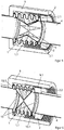
- perspektivisch und teilweise im Schnitt eine zweite Ausführungsform der erfindungsgemäßen Stellvorrichtung, bei der eine Rohrströmung mit einer Verschlussblende durchgelassen oder abgesperrt werden kann, hier in Durchlassposition; und
- Figur 6
- perspektivisch und teilweise im Schnitt die Stellvorrichtung gemäß
Figur 5 in Absperrposition. - Die in den Figuren dargestellte Stellvorrichtung besteht aus einem Wellrohrabschnitt 1 mit einer wellenförmigen Rohrwandung 1.1, einem außerhalb des Wellrohrabschnitts 1 angeordneten Außenstellelement 2 (in den
Figuren 1 bis 4 nicht extra dargestellt) und einem innerhalb des Wellrohrabschnitts 1 angeordneten Innenstellelement 3, wobei das Außenstellelement 2 mit dem Innenstellelement 3 wirkverbunden ausgebildet ist. - Wesentlich für alle möglichen Ausführungsformen der erfindungsgemäßen Stellvorrichtung ist, dass mindestens das Außen- oder das Innenstellelement 2, 3 zur Übertragung einer Kraft vom Außen- auf das Innenstellelement 2, 3 oder umgekehrt einen an die wellenförmige Rohrwandung 1.1 angepassten Kontaktbereich 2.1, 3.1 aufweist.
- Dabei ist bevorzugt vorgesehen, dass der Wellrohrabschnitt 1 wahlweise aus Kunststoff oder Metall gebildet ist. Zudem ist vorzugsweise an mindestens einer Seite des Wellrohrabschnittes 1 ein glattzylindrisches Rohrstück 4 fluiddicht anschließend angeordnet. Wellrohrabschnitt 1 und Rohrstück 4 können dabei (müssen aber nicht) einstückig ausgebildet sein.
- Bezüglich des Außenstellelements 2 ist bevorzugt vorgesehen, dass dieses an einem den Kontaktbereich 2.1 bildenden, vorzugsweise als Wellenschulter ausgebildeten, Übergangsteil zwischen dem Wellrohrabschnitt 1 und dem Rohrstück 4 angeordnet ist. Außerdem ist vorzugsweise das Außenstellelement 2 mindestens einen Abschnitt des Rohrstücks 4 vollständig umschließend und/oder das Rohrstück 4 hohlzylinderförmig umgreifend ausgebildet (siehe
Figuren 5 und 6 ). Im Falle eines beidendig fixierten Wellrohrabschnittes 1 ist das Außenstellelement 2 bevorzugt an einem mittleren Bereich des Wellrohrabschnittes 1 formschlüssig angreifend ausgebildet. - Wie ebenfalls in den
Figuren 5 und 6 zu erkennen ist, ist das Außenstellelement 2 vorzugsweise auf seiner dem Rohrstück 4 abgewandten Seite profiliert ausgebildet, wobei dieses erste Profil 2.2 im speziellen ein Wellen-, Zacken- oder Schraubenprofil ist. - Weiterhin ist es erfindungsgemäß möglich, dass ein mit dem Außenstellelement 2 kraftschlüssig verbundenes Schiebeelement 9 vorgesehen ist. Das Schiebeelement 9 ist vorzugsweise hohlzylinderförmig ausgebildet und umgreift Teile des Rohrstücks 4 und den Wellrohrabschnitt 1.
- Zusätzlich ist bevorzugt vorgesehen, dass das Schiebeelement 9 auf seiner dem Rohrstück 4 zugewandten Seite ein zweites Profil 9.1 aufweist und dass das oben genannte erste Profil 2.2 und das zweite Profil 9.1 kraftschlüssig ineinandergreifend ausgebildet sind.
- In Bezug auf das Innenstellelement 3 ist bevorzugt, dass dieses zumindest teilweise einen Außendurchmesser aufweist, der größer als der kleinste Innendurchmesser, aber kleiner als der größte Innendurchmesser des Wellrohrabschnitts 1 ist und/oder dass der Wellrohrabschnitt 1 als Teil einer mit einem Ventil 5 versehenen Verrohrung 6 und das Innenstellelement 3 mit dem Ventil 5 wirkverbunden ausgebildet ist. Ist das Ventil 5 nicht vollumpfänglich fluidisch dicht verschließbar ausgebildet, kann hier auch von einem Drosselelement statt von einem Ventil gesprochen werden.
- Im Weiteren werden die Besonderheiten zweier spezieller Ausführungsbeispiele der erfindungsgemäßen Stellvorrichtung beschrieben. Es ist dabei anzumerken, dass konstruktive Elemente dieser Beispiele auch beliebig miteinander kombiniert werden können und die folgende Beschreibung keinerlei Beschränkung der Erfindung auf ebendiese Beispiele darstellt.
- Ausführungsbeispiel 1 ist in den
Figuren 1 bis 4 gezeigt und weist bevorzugt ein Innenstellelement 3 auf, welches an seinem Umfangsrand mit den Kontaktbereich 3.1 bildenden Hakenelementen 3.1.1 versehen ist (Figur 4 ), welche in die wellenförmige Rohrwandung (1.1) eingreifen. - Weiterhin ist in diesem Fall die Verrohrung 6 aus dem Rohrstück 4 und einem seitlich vom Rohrstück 4 abzweigenden Zusatzrohrstück 7 gebildet und vorzugsweise das Ventil 5 in Form eines vom Wellrohrabschnitt 1 bis zu einem Übergangsbereich 8 zwischen dem Rohrstück 4 und dem Zusatzrohrstück 7 reichenden, wellrohrabschnittabgewandt stirnseitig verschlossenen und innerhalb des Rohrstücks 4 verschieblich gelagerten Zylinders mit mindestens einer an seiner Mantelfläche vorgesehenen Durchgangsöffnung 5.1 ausgebildet. Diese Form der erfindungsgemäßen Stellvorrichtung ist besonders für verzweigte Rohrleitungen geeignet.
- Die
Figuren 5 und 6 zeigen ein zweites Ausführungsbeispiel, bei dem das Ventil 5 innerhalb des Wellrohrabschnittes 1 angeordnet und das Innenstellelement 3 bevorzugt annähernd ringförmig ausgebildet ist. Weiterhin ist hierbei vorzugsweise das Ventil 5 in Verschlussstellung in Form zweier sich an ihrer Spitze berührender Kegel ausgebildet, wobei jeder Kegel eine gedachte Grundfläche 10 aufweist und diese Grundflächen 10 über Kontaktbereiche 10.1 mit der wellenförmigen Rohrwandung 1.1 wirkverbunden und zueinander verstellbar ausgebildet sind. Diese erfindungsgemäße Variante eignet sich besonders für eine Stellvorrichtung in einem geraden Rohr. - Die erfindungsgemäße Stellvorrichtung funktioniert wie folgt:
- Ausgehend von einem zunächst geöffneten Ventil (oder Drosseleinrichtung) 5 kann der Fluidfluss durch die Verrohrung 6 unterbrochen (oder gedrosselt) werden, indem das Außenstellelement 2 bewegt wird. Dies staucht den Wellrohrabschnitt 1 und verschiebt damit auch das Innenstellelement 3, welches mit dem Ventil 5 verbunden ist. Das Ventil 5 wird so geschlossen. Das Bewegen des Außenstellelements 2 kann per Hand, oder auch automatisch - beispielsweise mit einem Motor - erfolgen und zwar entweder direkt über das Außenstellelement 2 selbst, oder über das eventuell vorhandene Schiebeelement 9. Des weiteren kann neben dem Verschließen oder Drosseln des Fluidflusses durch die Verrohrung 6 auch eine Umleitung des Fluids bewirkt werden, wie es etwa im ersten Ausführungsbeispiel in den
Figuren 1 bis 3 der Fall ist. -
- 1
- Wellrohrabschnitt
- 1.1
- Wellenförmige Rohrwandung
- 2
- Außenstellelement
- 2.1
- Kontaktbereich
- 2.2
- Erstes Profil
- 3
- Innenstellelement
- 3.1
- Kontaktbereich
- 3.1.1
- Hakenelement
- 4
- Rohrstück
- 5
- Ventil
- 5.1
- Durchgangsöffnung
- 6
- Verrohrung
- 7
- Zusatzrohrstück
- 8
- Übergangsbereich
- 9
- Schiebeelement
- 9.1
- Zweites Profil
- 10
- Grundfläche
- 10.1
- Kontaktbereich
Claims (10)
- Stellvorrichtung, umfassend einen Wellrohrabschnitt (1) mit einer wellenförmigen Rohrwandung (1.1), ein außerhalb des Wellrohrabschnitts (1) angeordnetes Außenstellelement (2) und ein innerhalb des Wellrohrabschnitts (1) angeordnetes Innenstellelement (3), wobei das Außenstellelement (2) mit dem Innenstellelement (3) wirkverbunden ausgebildet ist,
dadurch gekennzeichnet,
dass mindestens das Außen- oder das Innenstellelement (2, 3) zur Übertragung einer Kraft vom Außen- auf das Innenstellelement (2, 3) oder umgekehrt einen an die wellenförmige Rohrwandung (1.1) angepassten Kontaktbereich (2.1, 3.1) aufweist. - Stellvorrichtung nach Anspruch 1,
dadurch gekennzeichnet,
dass das Außenstellelement (2) bei beidendig fixiertem Wellrohrabschnitt (1) an einem mittleren Bereich des Wellrohrabschnittes (1) formschlüssig angreifend ausgebildet ist. - Stellvorrichtung nach Anspruch 1 oder 2,
dadurch gekennzeichnet,
dass sich an mindestens einer Seite des Wellrohrabschnittes (1) ein glattzylindrisches Rohrstück (4) fluiddicht anschließend angeordnet ist. - Stellvorrichtung nach Anspruch 3,
dadurch gekennzeichnet,
dass das Außenstellelement (2) an einem den Kontaktbereich (2.1) bildenden, vorzugsweise als Wellenschulter ausgebildeten, Übergangsbereich zwischen dem Wellrohrabschnitt (1) und dem Rohrstück (4) angeordnet ist. - Stellvorrichtung nach einem der Ansprüche 1 bis 4,
dadurch gekennzeichnet,
dass das Innenstellelement (3) an seinem Umfangsrand mit den Kontaktbereich (3.1) bildenden Hakenelementen (3.1.1) versehen ist. - Stellvorrichtung nach einem der Ansprüche 1 bis 5,
dadurch gekennzeichnet,
dass das Innenstellelement (3) zumindest teilweise einen Außendurchmesser aufweist, der größer als der kleinste Innendurchmesser, aber kleiner als der größte Innendurchmesser des Wellrohrabschnitts (1) ist. - Stellvorrichtung nach Anspruch 1 bis 6,
dadurch gekennzeichnet,
dass der Wellrohrabschnitt (1) als Teil einer mit einem Ventil (5) versehenen Verrohrung (6) und das Innenstellelement (3) mit dem Ventil (5) wirkverbunden ausgebildet ist. - Stellvorrichtung nach Anspruch 7,
dadurch gekennzeichnet,
dass die Verrohrung (6) aus dem Rohrstück (4) und einem seitlich vom Rohrstück (4) abzweigenden Zusatzrohrstück (7) gebildet ist. - Stellvorrichtung nach Anspruch 7 und 8,
dadurch gekennzeichnet,
dass das Ventil (5) in Form eines vom Wellrohrabschnitt (1) bis zum Übergangsbereich (8) zwischen dem Rohrstück (4) und dem Zusatzrohrstück (7) reichenden, wellrohrabschnittabgewandt stirnseitig verschlossenen und innerhalb des Rohrstücks (4) verschieblich gelagerten Zylinders mit mindestens einer an seiner Mantelfläche vorgesehenen Durchgangsöffnung (5.1) ausgebildet ist. - Stellvorrichtung nach Anspruch 7,
dadurch gekennzeichnet,
dass das Ventil (5) in Verschlussstellung in Form zweier sich an ihrer Spitze berührender Kegel ausgebildet ist.
Applications Claiming Priority (1)
| Application Number | Priority Date | Filing Date | Title |
|---|---|---|---|
| DE102016100998.9A DE102016100998A1 (de) | 2016-01-21 | 2016-01-21 | Stellvorrichtung |
Related Child Applications (1)
| Application Number | Title | Priority Date | Filing Date |
|---|---|---|---|
| EP18190451.7 Division-Into | 2018-08-23 |
Publications (2)
| Publication Number | Publication Date |
|---|---|
| EP3196522A1 true EP3196522A1 (de) | 2017-07-26 |
| EP3196522B1 EP3196522B1 (de) | 2018-10-17 |
Family
ID=57821851
Family Applications (1)
| Application Number | Title | Priority Date | Filing Date |
|---|---|---|---|
| EP17151580.2A Active EP3196522B1 (de) | 2016-01-21 | 2017-01-16 | Stellvorrichtung |
Country Status (2)
| Country | Link |
|---|---|
| EP (1) | EP3196522B1 (de) |
| DE (1) | DE102016100998A1 (de) |
Citations (9)
| Publication number | Priority date | Publication date | Assignee | Title |
|---|---|---|---|---|
| US2106572A (en) * | 1934-05-14 | 1938-01-25 | Meagher Andrew Charles | Proportioning valve |
| FR1182363A (fr) * | 1957-07-12 | 1959-06-24 | Vanne à soufflet perfectionnée | |
| DE1289703B (de) | 1963-03-23 | 1969-02-20 | Medizintechnik Leipzig Veb | Pneumatisches Regelventil zur Regelung kleiner Durchflussmengen |
| NL6808736A (de) * | 1968-06-21 | 1969-12-23 | ||
| EP0165494A1 (de) * | 1984-05-24 | 1985-12-27 | EMIDE-METALLINDUSTRIE Gebr. Streicher | Küchengerät |
| US5207409A (en) * | 1992-06-09 | 1993-05-04 | Riikonen Esko A | Interchangeable pinch valve system |
| US6434353B1 (en) * | 1999-11-27 | 2002-08-13 | Samsung Electronics Co. | Ink feeding valve of a wet type electrophotographic printer |
| CN201359114Y (zh) * | 2009-03-18 | 2009-12-09 | 陈际军 | 一种恒温阀 |
| DE102014207674A1 (de) * | 2014-04-24 | 2015-10-29 | Schaeffler Technologies AG & Co. KG | Ventilanordnung |
-
2016
- 2016-01-21 DE DE102016100998.9A patent/DE102016100998A1/de not_active Ceased
-
2017
- 2017-01-16 EP EP17151580.2A patent/EP3196522B1/de active Active
Patent Citations (9)
| Publication number | Priority date | Publication date | Assignee | Title |
|---|---|---|---|---|
| US2106572A (en) * | 1934-05-14 | 1938-01-25 | Meagher Andrew Charles | Proportioning valve |
| FR1182363A (fr) * | 1957-07-12 | 1959-06-24 | Vanne à soufflet perfectionnée | |
| DE1289703B (de) | 1963-03-23 | 1969-02-20 | Medizintechnik Leipzig Veb | Pneumatisches Regelventil zur Regelung kleiner Durchflussmengen |
| NL6808736A (de) * | 1968-06-21 | 1969-12-23 | ||
| EP0165494A1 (de) * | 1984-05-24 | 1985-12-27 | EMIDE-METALLINDUSTRIE Gebr. Streicher | Küchengerät |
| US5207409A (en) * | 1992-06-09 | 1993-05-04 | Riikonen Esko A | Interchangeable pinch valve system |
| US6434353B1 (en) * | 1999-11-27 | 2002-08-13 | Samsung Electronics Co. | Ink feeding valve of a wet type electrophotographic printer |
| CN201359114Y (zh) * | 2009-03-18 | 2009-12-09 | 陈际军 | 一种恒温阀 |
| DE102014207674A1 (de) * | 2014-04-24 | 2015-10-29 | Schaeffler Technologies AG & Co. KG | Ventilanordnung |
Also Published As
| Publication number | Publication date |
|---|---|
| EP3196522B1 (de) | 2018-10-17 |
| DE102016100998A1 (de) | 2017-07-27 |
Similar Documents
| Publication | Publication Date | Title |
|---|---|---|
| EP2719932B1 (de) | Steigendes Handventil mit Hubbegrenzung | |
| DE202018105095U1 (de) | Tür- und Treppenschutzgitter mit ausrollbarer Trennwand | |
| DE102006057881C5 (de) | Spannbare Schelle | |
| EP1859329B1 (de) | Durchflussmengenregler | |
| DE102011006647B4 (de) | Mechanische Vorrichtung zur Realisierung einer Öffnung mit veränderlichen Öffnungsweiten | |
| EP3196522B1 (de) | Stellvorrichtung | |
| EP2302272B1 (de) | Ventilkartusche | |
| DE102014017036B3 (de) | Ventiltrieb für eine Brennkraftmaschine sowie entsprechende Brennkraftmaschine | |
| DE102005011947B3 (de) | Durchflussmengenregler | |
| EP2811096B1 (de) | Einzugsvorrichtung für einen Flügel einer Tür oder eines Fensters | |
| DE102011081064B4 (de) | Scheibensteuerung | |
| DE2050025B2 (de) | Eingriff Mischbatterie | |
| DE202020102122U1 (de) | Stellgerät für eine verfahrenstechnische Anlage | |
| DE102013101197B4 (de) | Membranventil | |
| DE102010039678B4 (de) | Stelleinrichtung für ein Ventil | |
| DE3309339A1 (de) | Mischbatterie | |
| DE102006056909A1 (de) | Heizkörperventil, insbesondere Einbauventil | |
| DE2150635C3 (de) | ||
| DE10162604A1 (de) | Heizkörperventil | |
| DE102019121944A1 (de) | Mischventil | |
| DE202007004023U1 (de) | Rückschlagventil | |
| WO2015039753A1 (de) | Doppelscheibenventil mit leckagesicherung | |
| AT410363B (de) | Gelenkstück zur verbindung zweier rohre | |
| DE202017006497U1 (de) | Spannring mit einem Spannbolzen | |
| EP3067595A1 (de) | Ventileinheit |
Legal Events
| Date | Code | Title | Description |
|---|---|---|---|
| PUAI | Public reference made under article 153(3) epc to a published international application that has entered the european phase |
Free format text: ORIGINAL CODE: 0009012 |
|
| STAA | Information on the status of an ep patent application or granted ep patent |
Free format text: STATUS: THE APPLICATION HAS BEEN PUBLISHED |
|
| AK | Designated contracting states |
Kind code of ref document: A1 Designated state(s): AL AT BE BG CH CY CZ DE DK EE ES FI FR GB GR HR HU IE IS IT LI LT LU LV MC MK MT NL NO PL PT RO RS SE SI SK SM TR |
|
| AX | Request for extension of the european patent |
Extension state: BA ME |
|
| STAA | Information on the status of an ep patent application or granted ep patent |
Free format text: STATUS: REQUEST FOR EXAMINATION WAS MADE |
|
| 17P | Request for examination filed |
Effective date: 20180119 |
|
| RBV | Designated contracting states (corrected) |
Designated state(s): AL AT BE BG CH CY CZ DE DK EE ES FI FR GB GR HR HU IE IS IT LI LT LU LV MC MK MT NL NO PL PT RO RS SE SI SK SM TR |
|
| RIC1 | Information provided on ipc code assigned before grant |
Ipc: F16K 11/07 20060101ALI20180223BHEP Ipc: F16K 7/02 20060101ALI20180223BHEP Ipc: F16K 31/44 20060101AFI20180223BHEP |
|
| GRAP | Despatch of communication of intention to grant a patent |
Free format text: ORIGINAL CODE: EPIDOSNIGR1 |
|
| STAA | Information on the status of an ep patent application or granted ep patent |
Free format text: STATUS: GRANT OF PATENT IS INTENDED |
|
| INTG | Intention to grant announced |
Effective date: 20180509 |
|
| GRAS | Grant fee paid |
Free format text: ORIGINAL CODE: EPIDOSNIGR3 |
|
| GRAA | (expected) grant |
Free format text: ORIGINAL CODE: 0009210 |
|
| STAA | Information on the status of an ep patent application or granted ep patent |
Free format text: STATUS: THE PATENT HAS BEEN GRANTED |
|
| AK | Designated contracting states |
Kind code of ref document: B1 Designated state(s): AL AT BE BG CH CY CZ DE DK EE ES FI FR GB GR HR HU IE IS IT LI LT LU LV MC MK MT NL NO PL PT RO RS SE SI SK SM TR |
|
| REG | Reference to a national code |
Ref country code: GB Ref legal event code: FG4D Free format text: NOT ENGLISH |
|
| REG | Reference to a national code |
Ref country code: CH Ref legal event code: EP |
|
| REG | Reference to a national code |
Ref country code: IE Ref legal event code: FG4D Free format text: LANGUAGE OF EP DOCUMENT: GERMAN |
|
| REG | Reference to a national code |
Ref country code: DE Ref legal event code: R096 Ref document number: 502017000240 Country of ref document: DE Ref country code: AT Ref legal event code: REF Ref document number: 1054455 Country of ref document: AT Kind code of ref document: T Effective date: 20181115 |
|
| REG | Reference to a national code |
Ref country code: NL Ref legal event code: MP Effective date: 20181017 |
|
| REG | Reference to a national code |
Ref country code: LT Ref legal event code: MG4D |
|
| PG25 | Lapsed in a contracting state [announced via postgrant information from national office to epo] |
Ref country code: NL Free format text: LAPSE BECAUSE OF FAILURE TO SUBMIT A TRANSLATION OF THE DESCRIPTION OR TO PAY THE FEE WITHIN THE PRESCRIBED TIME-LIMIT Effective date: 20181017 |
|
| PG25 | Lapsed in a contracting state [announced via postgrant information from national office to epo] |
Ref country code: FI Free format text: LAPSE BECAUSE OF FAILURE TO SUBMIT A TRANSLATION OF THE DESCRIPTION OR TO PAY THE FEE WITHIN THE PRESCRIBED TIME-LIMIT Effective date: 20181017 Ref country code: IS Free format text: LAPSE BECAUSE OF FAILURE TO SUBMIT A TRANSLATION OF THE DESCRIPTION OR TO PAY THE FEE WITHIN THE PRESCRIBED TIME-LIMIT Effective date: 20190217 Ref country code: BG Free format text: LAPSE BECAUSE OF FAILURE TO SUBMIT A TRANSLATION OF THE DESCRIPTION OR TO PAY THE FEE WITHIN THE PRESCRIBED TIME-LIMIT Effective date: 20190117 Ref country code: ES Free format text: LAPSE BECAUSE OF FAILURE TO SUBMIT A TRANSLATION OF THE DESCRIPTION OR TO PAY THE FEE WITHIN THE PRESCRIBED TIME-LIMIT Effective date: 20181017 Ref country code: LV Free format text: LAPSE BECAUSE OF FAILURE TO SUBMIT A TRANSLATION OF THE DESCRIPTION OR TO PAY THE FEE WITHIN THE PRESCRIBED TIME-LIMIT Effective date: 20181017 Ref country code: HR Free format text: LAPSE BECAUSE OF FAILURE TO SUBMIT A TRANSLATION OF THE DESCRIPTION OR TO PAY THE FEE WITHIN THE PRESCRIBED TIME-LIMIT Effective date: 20181017 Ref country code: PL Free format text: LAPSE BECAUSE OF FAILURE TO SUBMIT A TRANSLATION OF THE DESCRIPTION OR TO PAY THE FEE WITHIN THE PRESCRIBED TIME-LIMIT Effective date: 20181017 Ref country code: NO Free format text: LAPSE BECAUSE OF FAILURE TO SUBMIT A TRANSLATION OF THE DESCRIPTION OR TO PAY THE FEE WITHIN THE PRESCRIBED TIME-LIMIT Effective date: 20190117 Ref country code: LT Free format text: LAPSE BECAUSE OF FAILURE TO SUBMIT A TRANSLATION OF THE DESCRIPTION OR TO PAY THE FEE WITHIN THE PRESCRIBED TIME-LIMIT Effective date: 20181017 |
|
| PG25 | Lapsed in a contracting state [announced via postgrant information from national office to epo] |
Ref country code: PT Free format text: LAPSE BECAUSE OF FAILURE TO SUBMIT A TRANSLATION OF THE DESCRIPTION OR TO PAY THE FEE WITHIN THE PRESCRIBED TIME-LIMIT Effective date: 20190217 Ref country code: RS Free format text: LAPSE BECAUSE OF FAILURE TO SUBMIT A TRANSLATION OF THE DESCRIPTION OR TO PAY THE FEE WITHIN THE PRESCRIBED TIME-LIMIT Effective date: 20181017 Ref country code: SE Free format text: LAPSE BECAUSE OF FAILURE TO SUBMIT A TRANSLATION OF THE DESCRIPTION OR TO PAY THE FEE WITHIN THE PRESCRIBED TIME-LIMIT Effective date: 20181017 Ref country code: GR Free format text: LAPSE BECAUSE OF FAILURE TO SUBMIT A TRANSLATION OF THE DESCRIPTION OR TO PAY THE FEE WITHIN THE PRESCRIBED TIME-LIMIT Effective date: 20190118 Ref country code: AL Free format text: LAPSE BECAUSE OF FAILURE TO SUBMIT A TRANSLATION OF THE DESCRIPTION OR TO PAY THE FEE WITHIN THE PRESCRIBED TIME-LIMIT Effective date: 20181017 |
|
| REG | Reference to a national code |
Ref country code: DE Ref legal event code: R097 Ref document number: 502017000240 Country of ref document: DE |
|
| PG25 | Lapsed in a contracting state [announced via postgrant information from national office to epo] |
Ref country code: CZ Free format text: LAPSE BECAUSE OF FAILURE TO SUBMIT A TRANSLATION OF THE DESCRIPTION OR TO PAY THE FEE WITHIN THE PRESCRIBED TIME-LIMIT Effective date: 20181017 Ref country code: DK Free format text: LAPSE BECAUSE OF FAILURE TO SUBMIT A TRANSLATION OF THE DESCRIPTION OR TO PAY THE FEE WITHIN THE PRESCRIBED TIME-LIMIT Effective date: 20181017 |
|
| PLBE | No opposition filed within time limit |
Free format text: ORIGINAL CODE: 0009261 |
|
| STAA | Information on the status of an ep patent application or granted ep patent |
Free format text: STATUS: NO OPPOSITION FILED WITHIN TIME LIMIT |
|
| PG25 | Lapsed in a contracting state [announced via postgrant information from national office to epo] |
Ref country code: MC Free format text: LAPSE BECAUSE OF FAILURE TO SUBMIT A TRANSLATION OF THE DESCRIPTION OR TO PAY THE FEE WITHIN THE PRESCRIBED TIME-LIMIT Effective date: 20181017 Ref country code: SM Free format text: LAPSE BECAUSE OF FAILURE TO SUBMIT A TRANSLATION OF THE DESCRIPTION OR TO PAY THE FEE WITHIN THE PRESCRIBED TIME-LIMIT Effective date: 20181017 Ref country code: EE Free format text: LAPSE BECAUSE OF FAILURE TO SUBMIT A TRANSLATION OF THE DESCRIPTION OR TO PAY THE FEE WITHIN THE PRESCRIBED TIME-LIMIT Effective date: 20181017 Ref country code: RO Free format text: LAPSE BECAUSE OF FAILURE TO SUBMIT A TRANSLATION OF THE DESCRIPTION OR TO PAY THE FEE WITHIN THE PRESCRIBED TIME-LIMIT Effective date: 20181017 Ref country code: SK Free format text: LAPSE BECAUSE OF FAILURE TO SUBMIT A TRANSLATION OF THE DESCRIPTION OR TO PAY THE FEE WITHIN THE PRESCRIBED TIME-LIMIT Effective date: 20181017 |
|
| 26N | No opposition filed |
Effective date: 20190718 |
|
| PG25 | Lapsed in a contracting state [announced via postgrant information from national office to epo] |
Ref country code: LU Free format text: LAPSE BECAUSE OF NON-PAYMENT OF DUE FEES Effective date: 20190116 |
|
| REG | Reference to a national code |
Ref country code: BE Ref legal event code: MM Effective date: 20190131 |
|
| REG | Reference to a national code |
Ref country code: IE Ref legal event code: MM4A |
|
| PG25 | Lapsed in a contracting state [announced via postgrant information from national office to epo] |
Ref country code: SI Free format text: LAPSE BECAUSE OF FAILURE TO SUBMIT A TRANSLATION OF THE DESCRIPTION OR TO PAY THE FEE WITHIN THE PRESCRIBED TIME-LIMIT Effective date: 20181017 |
|
| PG25 | Lapsed in a contracting state [announced via postgrant information from national office to epo] |
Ref country code: BE Free format text: LAPSE BECAUSE OF NON-PAYMENT OF DUE FEES Effective date: 20190131 |
|
| PG25 | Lapsed in a contracting state [announced via postgrant information from national office to epo] |
Ref country code: IE Free format text: LAPSE BECAUSE OF NON-PAYMENT OF DUE FEES Effective date: 20190116 |
|
| PG25 | Lapsed in a contracting state [announced via postgrant information from national office to epo] |
Ref country code: TR Free format text: LAPSE BECAUSE OF FAILURE TO SUBMIT A TRANSLATION OF THE DESCRIPTION OR TO PAY THE FEE WITHIN THE PRESCRIBED TIME-LIMIT Effective date: 20181017 |
|
| PG25 | Lapsed in a contracting state [announced via postgrant information from national office to epo] |
Ref country code: MT Free format text: LAPSE BECAUSE OF FAILURE TO SUBMIT A TRANSLATION OF THE DESCRIPTION OR TO PAY THE FEE WITHIN THE PRESCRIBED TIME-LIMIT Effective date: 20181017 |
|
| REG | Reference to a national code |
Ref country code: CH Ref legal event code: PL |
|
| PG25 | Lapsed in a contracting state [announced via postgrant information from national office to epo] |
Ref country code: CH Free format text: LAPSE BECAUSE OF NON-PAYMENT OF DUE FEES Effective date: 20200131 Ref country code: LI Free format text: LAPSE BECAUSE OF NON-PAYMENT OF DUE FEES Effective date: 20200131 |
|
| PG25 | Lapsed in a contracting state [announced via postgrant information from national office to epo] |
Ref country code: CY Free format text: LAPSE BECAUSE OF FAILURE TO SUBMIT A TRANSLATION OF THE DESCRIPTION OR TO PAY THE FEE WITHIN THE PRESCRIBED TIME-LIMIT Effective date: 20181017 |
|
| PG25 | Lapsed in a contracting state [announced via postgrant information from national office to epo] |
Ref country code: HU Free format text: LAPSE BECAUSE OF FAILURE TO SUBMIT A TRANSLATION OF THE DESCRIPTION OR TO PAY THE FEE WITHIN THE PRESCRIBED TIME-LIMIT; INVALID AB INITIO Effective date: 20170116 |
|
| PGFP | Annual fee paid to national office [announced via postgrant information from national office to epo] |
Ref country code: AT Payment date: 20211220 Year of fee payment: 6 |
|
| PGFP | Annual fee paid to national office [announced via postgrant information from national office to epo] |
Ref country code: IT Payment date: 20220119 Year of fee payment: 6 Ref country code: FR Payment date: 20220131 Year of fee payment: 6 |
|
| PG25 | Lapsed in a contracting state [announced via postgrant information from national office to epo] |
Ref country code: MK Free format text: LAPSE BECAUSE OF FAILURE TO SUBMIT A TRANSLATION OF THE DESCRIPTION OR TO PAY THE FEE WITHIN THE PRESCRIBED TIME-LIMIT Effective date: 20181017 |
|
| REG | Reference to a national code |
Ref country code: DE Ref legal event code: R081 Ref document number: 502017000240 Country of ref document: DE Owner name: VIESSMANN CLIMATE SOLUTIONS SE, DE Free format text: FORMER OWNER: VIESSMANN WERKE GMBH & CO KG, 35108 ALLENDORF, DE Ref country code: DE Ref legal event code: R081 Ref document number: 502017000240 Country of ref document: DE Owner name: VIESSMANN GROUP GMBH & CO. KG, DE Free format text: FORMER OWNER: VIESSMANN WERKE GMBH & CO KG, 35108 ALLENDORF, DE |
|
| REG | Reference to a national code |
Ref country code: DE Ref legal event code: R081 Ref document number: 502017000240 Country of ref document: DE Owner name: VIESSMANN CLIMATE SOLUTIONS SE, DE Free format text: FORMER OWNER: VIESSMANN GROUP GMBH & CO. KG, 35108 ALLENDORF, DE |
|
| P01 | Opt-out of the competence of the unified patent court (upc) registered |
Effective date: 20230515 |
|
| REG | Reference to a national code |
Ref country code: AT Ref legal event code: MM01 Ref document number: 1054455 Country of ref document: AT Kind code of ref document: T Effective date: 20230116 |
|
| PG25 | Lapsed in a contracting state [announced via postgrant information from national office to epo] |
Ref country code: AT Free format text: LAPSE BECAUSE OF NON-PAYMENT OF DUE FEES Effective date: 20230116 |
|
| PG25 | Lapsed in a contracting state [announced via postgrant information from national office to epo] |
Ref country code: FR Free format text: LAPSE BECAUSE OF NON-PAYMENT OF DUE FEES Effective date: 20230131 |
|
| PG25 | Lapsed in a contracting state [announced via postgrant information from national office to epo] |
Ref country code: IT Free format text: LAPSE BECAUSE OF NON-PAYMENT OF DUE FEES Effective date: 20230116 |
|
| PGFP | Annual fee paid to national office [announced via postgrant information from national office to epo] |
Ref country code: DE Payment date: 20240130 Year of fee payment: 8 Ref country code: GB Payment date: 20240130 Year of fee payment: 8 |