EP3196458B1 - Kraftstoffinjektor-sprühloch - Google Patents
Kraftstoffinjektor-sprühloch Download PDFInfo
- Publication number
- EP3196458B1 EP3196458B1 EP17152527.2A EP17152527A EP3196458B1 EP 3196458 B1 EP3196458 B1 EP 3196458B1 EP 17152527 A EP17152527 A EP 17152527A EP 3196458 B1 EP3196458 B1 EP 3196458B1
- Authority
- EP
- European Patent Office
- Prior art keywords
- section
- length
- cross
- fuel injector
- inner portion
- Prior art date
- Legal status (The legal status is an assumption and is not a legal conclusion. Google has not performed a legal analysis and makes no representation as to the accuracy of the status listed.)
- Active
Links
Images
Classifications
-
- F—MECHANICAL ENGINEERING; LIGHTING; HEATING; WEAPONS; BLASTING
- F02—COMBUSTION ENGINES; HOT-GAS OR COMBUSTION-PRODUCT ENGINE PLANTS
- F02M—SUPPLYING COMBUSTION ENGINES IN GENERAL WITH COMBUSTIBLE MIXTURES OR CONSTITUENTS THEREOF
- F02M61/00—Fuel-injectors not provided for in groups F02M39/00 - F02M57/00 or F02M67/00
- F02M61/16—Details not provided for in, or of interest apart from, the apparatus of groups F02M61/02 - F02M61/14
- F02M61/18—Injection nozzles, e.g. having valve seats; Details of valve member seated ends, not otherwise provided for
- F02M61/1806—Injection nozzles, e.g. having valve seats; Details of valve member seated ends, not otherwise provided for characterised by the arrangement of discharge orifices, e.g. orientation or size
- F02M61/1833—Discharge orifices having changing cross sections, e.g. being divergent
-
- F—MECHANICAL ENGINEERING; LIGHTING; HEATING; WEAPONS; BLASTING
- F02—COMBUSTION ENGINES; HOT-GAS OR COMBUSTION-PRODUCT ENGINE PLANTS
- F02M—SUPPLYING COMBUSTION ENGINES IN GENERAL WITH COMBUSTIBLE MIXTURES OR CONSTITUENTS THEREOF
- F02M61/00—Fuel-injectors not provided for in groups F02M39/00 - F02M57/00 or F02M67/00
- F02M61/16—Details not provided for in, or of interest apart from, the apparatus of groups F02M61/02 - F02M61/14
- F02M61/18—Injection nozzles, e.g. having valve seats; Details of valve member seated ends, not otherwise provided for
- F02M61/1806—Injection nozzles, e.g. having valve seats; Details of valve member seated ends, not otherwise provided for characterised by the arrangement of discharge orifices, e.g. orientation or size
-
- F—MECHANICAL ENGINEERING; LIGHTING; HEATING; WEAPONS; BLASTING
- F02—COMBUSTION ENGINES; HOT-GAS OR COMBUSTION-PRODUCT ENGINE PLANTS
- F02M—SUPPLYING COMBUSTION ENGINES IN GENERAL WITH COMBUSTIBLE MIXTURES OR CONSTITUENTS THEREOF
- F02M61/00—Fuel-injectors not provided for in groups F02M39/00 - F02M57/00 or F02M67/00
- F02M61/16—Details not provided for in, or of interest apart from, the apparatus of groups F02M61/02 - F02M61/14
- F02M61/18—Injection nozzles, e.g. having valve seats; Details of valve member seated ends, not otherwise provided for
- F02M61/1806—Injection nozzles, e.g. having valve seats; Details of valve member seated ends, not otherwise provided for characterised by the arrangement of discharge orifices, e.g. orientation or size
- F02M61/1846—Dimensional characteristics of discharge orifices
-
- F—MECHANICAL ENGINEERING; LIGHTING; HEATING; WEAPONS; BLASTING
- F02—COMBUSTION ENGINES; HOT-GAS OR COMBUSTION-PRODUCT ENGINE PLANTS
- F02M—SUPPLYING COMBUSTION ENGINES IN GENERAL WITH COMBUSTIBLE MIXTURES OR CONSTITUENTS THEREOF
- F02M2200/00—Details of fuel-injection apparatus, not otherwise provided for
- F02M2200/06—Fuel-injection apparatus having means for preventing coking, e.g. of fuel injector discharge orifices or valve needles
Definitions
- the present invention relates to a fuel injector and more particularly to the shape of injection holes arranged to spray fuel out of the nozzle of the fuel injector.
- Coking of injection holes is a known problem occurring in fuel injectors.
- WO2015052031 discloses hole design having divergent tapered outlet portion reducing the hole length. This design has proven to be more suitable for gasoline direct injection injectors where the spray penetration reduction is a major target.
- Another design alternative is to have low taper and low rounding injection holes to ensure cavitation forming inside the injection hole at all injection conditions.
- the trade-off is that low taper and low inlet rounding holes usually have low hydraulic efficiency, which is disadvantageous for mixing, fuel economy, and soot emission.
- Another idea is to use a special injection scheme forcing cavitation to be generated in order to clean the coking forming. For instance, commanding a low needle lift injection event after an interval of regular operation time forces cavitation generation in the injection hole. Fuel economy is a drawback of this injection scheme which can furthermore cause cavitation damage in the injector.
- DE102005019580 , WO2013145451 and US20120138712 disclose prior art injection holes.
- a nozzle body of a fuel injector having a generally elongated shape extending along a main axis.
- the body has a peripheral wall defining an inner blind bore adapted to receive a needle valve, the body extending from a first end wherein opens the bore to a tip end wherein the peripheral wall closes forming a sac volume at the extremity of the bore.
- the nozzle body is further provided with injection holes arranged through the wall and extending from an inlet opening in the sac, to an outlet opening on the outer face of the wall.
- At least one of the injection holes comprises an inner portion and an outer portion, said two portions joining together in an intersection zone wherein the cross-section of the inner portion is smaller than the cross-section of the outer portion, so that said intersection area forms a step in the spray hole.
- intersection zone has a short length, the step being abrupt.
- the step is a micro step comprised between 1 ⁇ m and 10 ⁇ m, and preferably between 2 ⁇ m and 5 ⁇ m to the radius.
- the outer portion is tapered, the cross-section in the intersection zone being larger than the cross section of the outlet opening and, the length of the inner portion is longer than the length of the outer portion and, at least one of the injection holes comprises two steps such as, said hole comprises an inner portion, a first step, a middle portion, a second step and an outer portion.
- the inner portion is tapered, the cross-section of the inlet opening being larger than the cross-section in the intersection zone.
- the axial length of the inner portion is more than 2.5 time of the diameter of the injection hole outlet section.
- the length of the inner portion is preferably more than three time longer than the length of the outer portion.
- the invention further extends to a nozzle assembly of a fuel injector, said assembly comprising a nozzle body as described above and a needle valve member axially arranged in the bore of the body.
- the invention further extends to a fuel injector comprising a nozzle assembly as described above. More particularly the fuel injector may be a diesel fuel injector.
- a fuel injector 10 extending along a main axis X1 has a nozzle body 12 provided with a plurality of injection holes 14, each hole 14 extending along a hole axis X2 arranged in an axial plan containing the main axis X1.
- the injection holes 14 are pierced through the peripheral wall 16 of the nozzle body, the holes 14 extending from an inlet opening 18, having inlet cross-section S18, arranged in a sac volume 20 inside the nozzle body 12 to, an outlet opening 22, having cross-section S22, arranged on the outer face 24 of the peripheral wall 16.
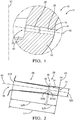
- a section of the injection hole 14 is represented on figures 1 and 2 .
- the hole 14 has a total length L14 divided in an inner portion 26 having length L26, an outer portion 28 having length L28, said two portions 26, 28, being aligned along the hole axis X2 and joining in an intersection zone 30 where the inner portion 26 has a cross-section SI30 smaller than the cross-section SO30 of the outer portion.
- This difference in cross-sections creates a step 32 between the inner and outer portions 26, 28, the aim of the step 32 being to disrupt, in use, the fuel flow and to generate wall cavitation and additionally turbulences along the peripheral face 34 of the outer portion 26, said wall cavitation and turbulences cleaning said peripheral face 34 from coking deposit.
- Figure 2 details the shape of an alternative embodiment of a hole 14 successfully modelled and tested for generating wall cavitation and additionally turbulences and cleaning the outer portion 28 from coking deposition.
- the length L26 of the inner portion 26 in the axial direction along X2 is more than 2.5 times of the diameter of the outlet section S22.
- the ratio of the length L26 of the inner portion 26 over the diameter of the outlet section S22 is preferably superior to 2.5.
- the length L26 of the inner portion 26 is axially X2 longer than the length L28 of the outer portion 28. A ratio of three has provided good results considering that other length ratio smaller than ten have also proven good interest.
- a ratio of ten positions means that the outer portion 28 is very short, the intersection zone 30 being in the vicinity of the outlet opening 22, the outer portion 28 being just a tenth of the total length L14.
- the inner portion 26 is slightly convergent, or tapered, as having the inlet opening 18 cross-section S18 a little larger than the intersection zone 30 opening cross-section SI30.
- the outer portion 28 is also slightly convergent, or tapered, the section of said outer portion diminishing from the cross-section SO30 in the intersection zone to the cross-section S22 of the outlet opening 22.
- the shape of the hole 14 may have a portions lengths ratio L26/L28 larger than five, meaning the outer portion is quite short relative to the inner portion, and a ratio of the outer portion length over the outlet section diameter L28/S22 not larger than 1.5.
- the outer portion 28 can be parallel or even slightly divergent, with a taper smaller than 3 degrees, without significant disadvantage to the hydraulic efficiency of the nozzle or to the fuel spray momentum concentration.
- the step 32 of one to ten, but preferably two to five micrometers to the radius has proven to be efficient.
- the difference in diameters between the sections SI30, SO30 of the two portions 26, 28, joining in the intersection zone 30 is comprised between two to twenty, but preferably four and ten micrometers ( ⁇ m).
- intersection zone 30 is represented conical but, considering a general hole diameter of approximately 100 ⁇ m and a step of few microns, the intersection zone 30 can be any abrupt shape provided said step generates the required wall cavitation and additional turbulences.
- abrupt is to be interpreted as the length of the intersection zone 30 should be as small as possible, the sum of the lengths L26, L28, of the inner and outer portions being as close to the total length L14 of the hole.
- the injection hole 14 can be provided with several intersection zones creating several steps 32. For instance, each step generating, in use, wall cavitation that would clean the following hole portion.
Landscapes
- Engineering & Computer Science (AREA)
- Chemical & Material Sciences (AREA)
- Combustion & Propulsion (AREA)
- Mechanical Engineering (AREA)
- General Engineering & Computer Science (AREA)
- Fuel-Injection Apparatus (AREA)
Claims (7)
- Düsenkörper (12) eines Kraftstoffinjektors (10), wobei der Körper eine allgemein längliche Form hat, die sich entlang einer Hauptachse (X1) erstreckt, wobei der Körper eine Umfangswand (16) hat, die eine innere Sackbohrung definiert, die ausgebildet ist zur Aufnahme eines Nadelventils, wobei sich der Körper von einem ersten Ende, an dem die Bohrung öffnet, zu einem Spitzenende erstreckt, an dem sich die Umfangswand schließt und ein Beutelvolumen (20) an dem Ende der Bohrung bildet, wobei der Düsenkörper (12) weiter mit Einspritzlöchern (14) vorgesehen ist, die durch die Wand (16) hindurch angeordnet sind und sich von einer Einlassöffnung (18) in dem Beutel (20) zu einer Auslassöffnung (22) an der Außenseite (24) der Wand erstrecken,
wobei zumindest eines der Einspritzlöcher (14) einen inneren Abschnitt (26) und einen äußeren Abschnitt (28) aufweist, wobei die zwei Abschnitte in einer Schnittzone (30) kurzer Länge verbunden sind, wobei der Querschnitt des inneren Abschnitts kleiner als der Querschnitt (SO30) des äußeren Abschnitts ist, so dass der Schnittbereich eine abrupte Stufe (32) in dem Einspritzloch (14) bildet,
und wobei die Stufe (32) eine Mikrostufe ist, die zwischen 1 µm und 10 µm und vorzugsweise zwischen 2 µm und 5 µm zu dem Radius liegt,
wobei die Länge (L26) des inneren Abschnitts (26) länger (L26) ist als die Länge (L28) des äußeren Abschnitts (28), und dadurch gekennzeichnet, dass sich der äußere Abschnitt (28) verjüngt, wobei der Querschnitt (SO30) in der Schnittzone größer ist als der Querschnitt (S22) der Auslassöffnung, und dadurch, dass
zumindest eines der Einspritzlöcher (14) zwei Stufen (32) aufweist derart, dass das Loch (14) einen inneren Abschnitt (26), eine erste Stufe (32), einen Mittelabschnitt, eine zweite Stufe (32) und einen äußeren Abschnitt (28) aufweist. - Körper (12) gemäß dem vorhergehenden Anspruch, wobei sich der innere Abschnitt (26) verjüngt, wobei der Querschnitt (S18) der Einlassöffnung größer ist als der Querschnitt (SI30) in der Schnittzone.
- Körper (12) gemäß einem der vorhergehenden Ansprüche, wobei die axiale Länge (L26) des inneren Abschnitts (26) mehr als das 2,5-fache des Durchmessers des Einspritzloch-Auslassabschnitts S22 beträgt.
- Körper (12) gemäß einem der vorhergehenden Ansprüche, wobei die Länge (L26) des inneren Abschnitts (26) vorzugsweise mehr als dreimal länger (L26) ist als die Länge (L28) des äußeren Abschnitts (28).
- Düsenanordnung eines Kraftstoffinjektors (10), wobei die Anordnung einen Düsenkörper (12) gemäß einem der vorhergehenden Ansprüche und ein Nadelventilelement aufweist, das in der Bohrung des Körpers (12) axial (X1) angeordnet ist.
- Kraftstoffinjektor (10) mit einer Düsenanordnung gemäß Anspruch 5.
- Kraftstoffinjektor (10) gemäß Anspruch 6, wobei der Injektor ein Dieselkraftstoffinjektor ist.
Applications Claiming Priority (1)
| Application Number | Priority Date | Filing Date | Title |
|---|---|---|---|
| GBGB1601184.3A GB201601184D0 (en) | 2016-01-22 | 2016-01-22 | Fuel injector spray hole |
Publications (2)
| Publication Number | Publication Date |
|---|---|
| EP3196458A1 EP3196458A1 (de) | 2017-07-26 |
| EP3196458B1 true EP3196458B1 (de) | 2019-11-13 |
Family
ID=55534767
Family Applications (1)
| Application Number | Title | Priority Date | Filing Date |
|---|---|---|---|
| EP17152527.2A Active EP3196458B1 (de) | 2016-01-22 | 2017-01-20 | Kraftstoffinjektor-sprühloch |
Country Status (2)
| Country | Link |
|---|---|
| EP (1) | EP3196458B1 (de) |
| GB (1) | GB201601184D0 (de) |
Family Cites Families (5)
| Publication number | Priority date | Publication date | Assignee | Title |
|---|---|---|---|---|
| DE10354467A1 (de) * | 2003-11-21 | 2005-06-09 | Robert Bosch Gmbh | Brennstoffeinspritzventil |
| JP4127237B2 (ja) * | 2004-04-28 | 2008-07-30 | 株式会社デンソー | 燃料噴射ノズル |
| KR101198805B1 (ko) * | 2010-12-02 | 2012-11-07 | 현대자동차주식회사 | 차량용 인젝터 |
| JP5959892B2 (ja) * | 2012-03-26 | 2016-08-02 | 日立オートモティブシステムズ株式会社 | 火花点火式燃料噴射弁 |
| DE102013220494A1 (de) | 2013-10-10 | 2015-04-16 | Continental Automotive Gmbh | Düsenkörper für ein Einspritzventil und Einspritzventil |
-
2016
- 2016-01-22 GB GBGB1601184.3A patent/GB201601184D0/en not_active Ceased
-
2017
- 2017-01-20 EP EP17152527.2A patent/EP3196458B1/de active Active
Non-Patent Citations (1)
| Title |
|---|
| None * |
Also Published As
| Publication number | Publication date |
|---|---|
| EP3196458A1 (de) | 2017-07-26 |
| GB201601184D0 (en) | 2016-03-09 |
Similar Documents
| Publication | Publication Date | Title |
|---|---|---|
| US8544770B2 (en) | Spray hole profile | |
| CN101144449B (zh) | 用于优化内燃机喷嘴的方法 | |
| JP5853023B2 (ja) | 燃料噴射弁 | |
| RU2014110063A (ru) | Клапан для текучей среды | |
| EP2884090B1 (de) | Düsenkörper und Kraftstoffeinspritzventil | |
| EP2466207A3 (de) | Kraftstoffdüse zur Kraftstoffzerstäubung mit doppeltem Auslass | |
| JP2019116895A (ja) | 非圧印加工の三次元ノズル出口面を備えた燃料噴射器 | |
| JP2009013985A (ja) | 複式噴霧噴射ノズル | |
| JP5044335B2 (ja) | 燃料噴射ノズル | |
| EP2808533B1 (de) | Kraftstoffeinspritzdüse | |
| JP2009138736A (ja) | 噴射ノズル | |
| WO2021079657A1 (ja) | 液体燃料噴射器 | |
| CN102132029A (zh) | 燃料喷射阀 | |
| US9828960B2 (en) | Valve for metering a flowing medium | |
| EP3196458A1 (de) | Kraftstoffinjektor-sprühloch | |
| DE102005019580B4 (de) | Kraftstoffeinspritzdüse | |
| DE102005017420A1 (de) | Brennstoffeinspritzventil | |
| CN100494668C (zh) | 一种燃油喷射器以及一种包含这种喷射器的发动机 | |
| JP4529992B2 (ja) | 噴孔プレートおよびそれを備えた燃料噴射弁 | |
| JP5353731B2 (ja) | 噴射ノズル | |
| US12049860B2 (en) | Nozzle for a fuel injector | |
| EP2405127A1 (de) | Kraftstoffeinspritzdüse für Verbrennungsmotoren | |
| JP2007534891A (ja) | 非対称型パンチ | |
| JP2016089770A (ja) | 燃料噴射弁 | |
| CN220036805U (zh) | 喷油嘴及具有其的喷油器 |
Legal Events
| Date | Code | Title | Description |
|---|---|---|---|
| PUAI | Public reference made under article 153(3) epc to a published international application that has entered the european phase |
Free format text: ORIGINAL CODE: 0009012 |
|
| STAA | Information on the status of an ep patent application or granted ep patent |
Free format text: STATUS: THE APPLICATION HAS BEEN PUBLISHED |
|
| AK | Designated contracting states |
Kind code of ref document: A1 Designated state(s): AL AT BE BG CH CY CZ DE DK EE ES FI FR GB GR HR HU IE IS IT LI LT LU LV MC MK MT NL NO PL PT RO RS SE SI SK SM TR |
|
| AX | Request for extension of the european patent |
Extension state: BA ME |
|
| STAA | Information on the status of an ep patent application or granted ep patent |
Free format text: STATUS: REQUEST FOR EXAMINATION WAS MADE |
|
| 17P | Request for examination filed |
Effective date: 20180126 |
|
| RBV | Designated contracting states (corrected) |
Designated state(s): AL AT BE BG CH CY CZ DE DK EE ES FI FR GB GR HR HU IE IS IT LI LT LU LV MC MK MT NL NO PL PT RO RS SE SI SK SM TR |
|
| STAA | Information on the status of an ep patent application or granted ep patent |
Free format text: STATUS: EXAMINATION IS IN PROGRESS |
|
| 17Q | First examination report despatched |
Effective date: 20181203 |
|
| RAP1 | Party data changed (applicant data changed or rights of an application transferred) |
Owner name: DELPHI TECHNOLOGIES IP LIMITED |
|
| GRAP | Despatch of communication of intention to grant a patent |
Free format text: ORIGINAL CODE: EPIDOSNIGR1 |
|
| INTG | Intention to grant announced |
Effective date: 20190614 |
|
| STAA | Information on the status of an ep patent application or granted ep patent |
Free format text: STATUS: GRANT OF PATENT IS INTENDED |
|
| GRAS | Grant fee paid |
Free format text: ORIGINAL CODE: EPIDOSNIGR3 |
|
| GRAA | (expected) grant |
Free format text: ORIGINAL CODE: 0009210 |
|
| STAA | Information on the status of an ep patent application or granted ep patent |
Free format text: STATUS: THE PATENT HAS BEEN GRANTED |
|
| AK | Designated contracting states |
Kind code of ref document: B1 Designated state(s): AL AT BE BG CH CY CZ DE DK EE ES FI FR GB GR HR HU IE IS IT LI LT LU LV MC MK MT NL NO PL PT RO RS SE SI SK SM TR |
|
| REG | Reference to a national code |
Ref country code: CH Ref legal event code: EP Ref country code: AT Ref legal event code: REF Ref document number: 1201910 Country of ref document: AT Kind code of ref document: T Effective date: 20191115 |
|
| REG | Reference to a national code |
Ref country code: DE Ref legal event code: R096 Ref document number: 602017008547 Country of ref document: DE |
|
| REG | Reference to a national code |
Ref country code: IE Ref legal event code: FG4D |
|
| REG | Reference to a national code |
Ref country code: NL Ref legal event code: MP Effective date: 20191113 |
|
| REG | Reference to a national code |
Ref country code: LT Ref legal event code: MG4D |
|
| PG25 | Lapsed in a contracting state [announced via postgrant information from national office to epo] |
Ref country code: GR Free format text: LAPSE BECAUSE OF FAILURE TO SUBMIT A TRANSLATION OF THE DESCRIPTION OR TO PAY THE FEE WITHIN THE PRESCRIBED TIME-LIMIT Effective date: 20200214 Ref country code: PT Free format text: LAPSE BECAUSE OF FAILURE TO SUBMIT A TRANSLATION OF THE DESCRIPTION OR TO PAY THE FEE WITHIN THE PRESCRIBED TIME-LIMIT Effective date: 20200313 Ref country code: NO Free format text: LAPSE BECAUSE OF FAILURE TO SUBMIT A TRANSLATION OF THE DESCRIPTION OR TO PAY THE FEE WITHIN THE PRESCRIBED TIME-LIMIT Effective date: 20200213 Ref country code: PL Free format text: LAPSE BECAUSE OF FAILURE TO SUBMIT A TRANSLATION OF THE DESCRIPTION OR TO PAY THE FEE WITHIN THE PRESCRIBED TIME-LIMIT Effective date: 20191113 Ref country code: LT Free format text: LAPSE BECAUSE OF FAILURE TO SUBMIT A TRANSLATION OF THE DESCRIPTION OR TO PAY THE FEE WITHIN THE PRESCRIBED TIME-LIMIT Effective date: 20191113 Ref country code: SE Free format text: LAPSE BECAUSE OF FAILURE TO SUBMIT A TRANSLATION OF THE DESCRIPTION OR TO PAY THE FEE WITHIN THE PRESCRIBED TIME-LIMIT Effective date: 20191113 Ref country code: LV Free format text: LAPSE BECAUSE OF FAILURE TO SUBMIT A TRANSLATION OF THE DESCRIPTION OR TO PAY THE FEE WITHIN THE PRESCRIBED TIME-LIMIT Effective date: 20191113 Ref country code: NL Free format text: LAPSE BECAUSE OF FAILURE TO SUBMIT A TRANSLATION OF THE DESCRIPTION OR TO PAY THE FEE WITHIN THE PRESCRIBED TIME-LIMIT Effective date: 20191113 Ref country code: FI Free format text: LAPSE BECAUSE OF FAILURE TO SUBMIT A TRANSLATION OF THE DESCRIPTION OR TO PAY THE FEE WITHIN THE PRESCRIBED TIME-LIMIT Effective date: 20191113 Ref country code: BG Free format text: LAPSE BECAUSE OF FAILURE TO SUBMIT A TRANSLATION OF THE DESCRIPTION OR TO PAY THE FEE WITHIN THE PRESCRIBED TIME-LIMIT Effective date: 20200213 |
|
| PG25 | Lapsed in a contracting state [announced via postgrant information from national office to epo] |
Ref country code: HR Free format text: LAPSE BECAUSE OF FAILURE TO SUBMIT A TRANSLATION OF THE DESCRIPTION OR TO PAY THE FEE WITHIN THE PRESCRIBED TIME-LIMIT Effective date: 20191113 Ref country code: RS Free format text: LAPSE BECAUSE OF FAILURE TO SUBMIT A TRANSLATION OF THE DESCRIPTION OR TO PAY THE FEE WITHIN THE PRESCRIBED TIME-LIMIT Effective date: 20191113 Ref country code: IS Free format text: LAPSE BECAUSE OF FAILURE TO SUBMIT A TRANSLATION OF THE DESCRIPTION OR TO PAY THE FEE WITHIN THE PRESCRIBED TIME-LIMIT Effective date: 20200313 |
|
| PG25 | Lapsed in a contracting state [announced via postgrant information from national office to epo] |
Ref country code: AL Free format text: LAPSE BECAUSE OF FAILURE TO SUBMIT A TRANSLATION OF THE DESCRIPTION OR TO PAY THE FEE WITHIN THE PRESCRIBED TIME-LIMIT Effective date: 20191113 |
|
| PG25 | Lapsed in a contracting state [announced via postgrant information from national office to epo] |
Ref country code: DK Free format text: LAPSE BECAUSE OF FAILURE TO SUBMIT A TRANSLATION OF THE DESCRIPTION OR TO PAY THE FEE WITHIN THE PRESCRIBED TIME-LIMIT Effective date: 20191113 Ref country code: EE Free format text: LAPSE BECAUSE OF FAILURE TO SUBMIT A TRANSLATION OF THE DESCRIPTION OR TO PAY THE FEE WITHIN THE PRESCRIBED TIME-LIMIT Effective date: 20191113 Ref country code: CZ Free format text: LAPSE BECAUSE OF FAILURE TO SUBMIT A TRANSLATION OF THE DESCRIPTION OR TO PAY THE FEE WITHIN THE PRESCRIBED TIME-LIMIT Effective date: 20191113 Ref country code: ES Free format text: LAPSE BECAUSE OF FAILURE TO SUBMIT A TRANSLATION OF THE DESCRIPTION OR TO PAY THE FEE WITHIN THE PRESCRIBED TIME-LIMIT Effective date: 20191113 Ref country code: RO Free format text: LAPSE BECAUSE OF FAILURE TO SUBMIT A TRANSLATION OF THE DESCRIPTION OR TO PAY THE FEE WITHIN THE PRESCRIBED TIME-LIMIT Effective date: 20191113 |
|
| REG | Reference to a national code |
Ref country code: DE Ref legal event code: R097 Ref document number: 602017008547 Country of ref document: DE |
|
| REG | Reference to a national code |
Ref country code: AT Ref legal event code: MK05 Ref document number: 1201910 Country of ref document: AT Kind code of ref document: T Effective date: 20191113 |
|
| PG25 | Lapsed in a contracting state [announced via postgrant information from national office to epo] |
Ref country code: MC Free format text: LAPSE BECAUSE OF FAILURE TO SUBMIT A TRANSLATION OF THE DESCRIPTION OR TO PAY THE FEE WITHIN THE PRESCRIBED TIME-LIMIT Effective date: 20191113 Ref country code: SK Free format text: LAPSE BECAUSE OF FAILURE TO SUBMIT A TRANSLATION OF THE DESCRIPTION OR TO PAY THE FEE WITHIN THE PRESCRIBED TIME-LIMIT Effective date: 20191113 Ref country code: SM Free format text: LAPSE BECAUSE OF FAILURE TO SUBMIT A TRANSLATION OF THE DESCRIPTION OR TO PAY THE FEE WITHIN THE PRESCRIBED TIME-LIMIT Effective date: 20191113 |
|
| REG | Reference to a national code |
Ref country code: CH Ref legal event code: PL |
|
| PLBE | No opposition filed within time limit |
Free format text: ORIGINAL CODE: 0009261 |
|
| STAA | Information on the status of an ep patent application or granted ep patent |
Free format text: STATUS: NO OPPOSITION FILED WITHIN TIME LIMIT |
|
| REG | Reference to a national code |
Ref country code: BE Ref legal event code: MM Effective date: 20200131 |
|
| 26N | No opposition filed |
Effective date: 20200814 |
|
| PG25 | Lapsed in a contracting state [announced via postgrant information from national office to epo] |
Ref country code: LU Free format text: LAPSE BECAUSE OF NON-PAYMENT OF DUE FEES Effective date: 20200120 |
|
| PG25 | Lapsed in a contracting state [announced via postgrant information from national office to epo] |
Ref country code: SI Free format text: LAPSE BECAUSE OF FAILURE TO SUBMIT A TRANSLATION OF THE DESCRIPTION OR TO PAY THE FEE WITHIN THE PRESCRIBED TIME-LIMIT Effective date: 20191113 Ref country code: BE Free format text: LAPSE BECAUSE OF NON-PAYMENT OF DUE FEES Effective date: 20200131 Ref country code: CH Free format text: LAPSE BECAUSE OF NON-PAYMENT OF DUE FEES Effective date: 20200131 Ref country code: AT Free format text: LAPSE BECAUSE OF FAILURE TO SUBMIT A TRANSLATION OF THE DESCRIPTION OR TO PAY THE FEE WITHIN THE PRESCRIBED TIME-LIMIT Effective date: 20191113 Ref country code: LI Free format text: LAPSE BECAUSE OF NON-PAYMENT OF DUE FEES Effective date: 20200131 |
|
| PG25 | Lapsed in a contracting state [announced via postgrant information from national office to epo] |
Ref country code: IE Free format text: LAPSE BECAUSE OF NON-PAYMENT OF DUE FEES Effective date: 20200120 Ref country code: IT Free format text: LAPSE BECAUSE OF FAILURE TO SUBMIT A TRANSLATION OF THE DESCRIPTION OR TO PAY THE FEE WITHIN THE PRESCRIBED TIME-LIMIT Effective date: 20191113 |
|
| PG25 | Lapsed in a contracting state [announced via postgrant information from national office to epo] |
Ref country code: TR Free format text: LAPSE BECAUSE OF FAILURE TO SUBMIT A TRANSLATION OF THE DESCRIPTION OR TO PAY THE FEE WITHIN THE PRESCRIBED TIME-LIMIT Effective date: 20191113 Ref country code: MT Free format text: LAPSE BECAUSE OF FAILURE TO SUBMIT A TRANSLATION OF THE DESCRIPTION OR TO PAY THE FEE WITHIN THE PRESCRIBED TIME-LIMIT Effective date: 20191113 Ref country code: CY Free format text: LAPSE BECAUSE OF FAILURE TO SUBMIT A TRANSLATION OF THE DESCRIPTION OR TO PAY THE FEE WITHIN THE PRESCRIBED TIME-LIMIT Effective date: 20191113 |
|
| PG25 | Lapsed in a contracting state [announced via postgrant information from national office to epo] |
Ref country code: MK Free format text: LAPSE BECAUSE OF FAILURE TO SUBMIT A TRANSLATION OF THE DESCRIPTION OR TO PAY THE FEE WITHIN THE PRESCRIBED TIME-LIMIT Effective date: 20191113 |
|
| GRAP | Despatch of communication of intention to grant a patent |
Free format text: ORIGINAL CODE: EPIDOSNIGR1 |
|
| P01 | Opt-out of the competence of the unified patent court (upc) registered |
Effective date: 20230327 |
|
| REG | Reference to a national code |
Ref country code: DE Ref legal event code: R081 Ref document number: 602017008547 Country of ref document: DE Owner name: PHINIA DELPHI LUXEMBOURG SARL, LU Free format text: FORMER OWNER: DELPHI TECHNOLOGIES IP LIMITED, ST. MICHAEL, BB |
|
| REG | Reference to a national code |
Ref country code: GB Ref legal event code: 732E Free format text: REGISTERED BETWEEN 20240725 AND 20240731 |
|
| PGFP | Annual fee paid to national office [announced via postgrant information from national office to epo] |
Ref country code: GB Payment date: 20251211 Year of fee payment: 10 |
|
| PGFP | Annual fee paid to national office [announced via postgrant information from national office to epo] |
Ref country code: FR Payment date: 20251216 Year of fee payment: 10 |
|
| PGFP | Annual fee paid to national office [announced via postgrant information from national office to epo] |
Ref country code: DE Payment date: 20251222 Year of fee payment: 10 |