EP3196152B1 - Modularer sockel zur herstellung von installationen und verfahren zur lagerung mittels stapelung und bewegung von kästen - Google Patents
Modularer sockel zur herstellung von installationen und verfahren zur lagerung mittels stapelung und bewegung von kästen Download PDFInfo
- Publication number
- EP3196152B1 EP3196152B1 EP15842436.6A EP15842436A EP3196152B1 EP 3196152 B1 EP3196152 B1 EP 3196152B1 EP 15842436 A EP15842436 A EP 15842436A EP 3196152 B1 EP3196152 B1 EP 3196152B1
- Authority
- EP
- European Patent Office
- Prior art keywords
- boxes
- robot
- box
- movement
- stacking
- Prior art date
- Legal status (The legal status is an assumption and is not a legal conclusion. Google has not performed a legal analysis and makes no representation as to the accuracy of the status listed.)
- Active
Links
Images













Classifications
-
- B—PERFORMING OPERATIONS; TRANSPORTING
- B65—CONVEYING; PACKING; STORING; HANDLING THIN OR FILAMENTARY MATERIAL
- B65G—TRANSPORT OR STORAGE DEVICES, e.g. CONVEYORS FOR LOADING OR TIPPING, SHOP CONVEYOR SYSTEMS OR PNEUMATIC TUBE CONVEYORS
- B65G1/00—Storing articles, individually or in orderly arrangement, in warehouses or magazines
- B65G1/02—Storage devices
- B65G1/04—Storage devices mechanical
- B65G1/06—Storage devices mechanical with means for presenting articles for removal at predetermined position or level
-
- B—PERFORMING OPERATIONS; TRANSPORTING
- B65—CONVEYING; PACKING; STORING; HANDLING THIN OR FILAMENTARY MATERIAL
- B65G—TRANSPORT OR STORAGE DEVICES, e.g. CONVEYORS FOR LOADING OR TIPPING, SHOP CONVEYOR SYSTEMS OR PNEUMATIC TUBE CONVEYORS
- B65G1/00—Storing articles, individually or in orderly arrangement, in warehouses or magazines
- B65G1/02—Storage devices
- B65G1/04—Storage devices mechanical
- B65G1/0471—Storage devices mechanical with access from beneath
-
- B—PERFORMING OPERATIONS; TRANSPORTING
- B65—CONVEYING; PACKING; STORING; HANDLING THIN OR FILAMENTARY MATERIAL
- B65G—TRANSPORT OR STORAGE DEVICES, e.g. CONVEYORS FOR LOADING OR TIPPING, SHOP CONVEYOR SYSTEMS OR PNEUMATIC TUBE CONVEYORS
- B65G1/00—Storing articles, individually or in orderly arrangement, in warehouses or magazines
- B65G1/02—Storage devices
- B65G1/04—Storage devices mechanical
-
- G—PHYSICS
- G06—COMPUTING OR CALCULATING; COUNTING
- G06N—COMPUTING ARRANGEMENTS BASED ON SPECIFIC COMPUTATIONAL MODELS
- G06N3/00—Computing arrangements based on biological models
- G06N3/004—Artificial life, i.e. computing arrangements simulating life
- G06N3/008—Artificial life, i.e. computing arrangements simulating life based on physical entities controlled by simulated intelligence so as to replicate intelligent life forms, e.g. based on robots replicating pets or humans in their appearance or behaviour
-
- B—PERFORMING OPERATIONS; TRANSPORTING
- B65—CONVEYING; PACKING; STORING; HANDLING THIN OR FILAMENTARY MATERIAL
- B65G—TRANSPORT OR STORAGE DEVICES, e.g. CONVEYORS FOR LOADING OR TIPPING, SHOP CONVEYOR SYSTEMS OR PNEUMATIC TUBE CONVEYORS
- B65G1/00—Storing articles, individually or in orderly arrangement, in warehouses or magazines
-
- G—PHYSICS
- G06—COMPUTING OR CALCULATING; COUNTING
- G06N—COMPUTING ARRANGEMENTS BASED ON SPECIFIC COMPUTATIONAL MODELS
- G06N3/00—Computing arrangements based on biological models
Definitions
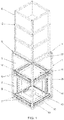
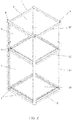
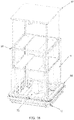
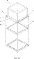
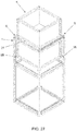
- the present invention relates to a structure in parallelepipedic tower shape, with square or rectangular base, which constitutes a modular unit that can be adjusted side by side with other units of the same type, which makes it possible to compose a variable installation, where each unit or base presents three functional details defined along its height and, for this purpose, each tower presents one ground floor, one first floor above the previous one and one functional top.
- the ground floor and the first floor are equally provided with tracks, while the top is a point of support for stacked boxes or containers.
- On the ground floor works a robot defined as lifting type, while above the same, on the first floor, works a robot defined as movement type.
- the stacked boxes are moved in the vertical direction by the first lifting robot, whose lift overpass the movement robot to perform this function, which allows the movement of the first bottom box supported on the top of the base up to the first floor and over the movement robot.
- the first lifting robot whose lift overpass the movement robot to perform this function, which allows the movement of the first bottom box supported on the top of the base up to the first floor and over the movement robot.
- such displacement of the first box from the bottom to up occurs along with the driving of locks and, thus, when the stack of boxes is moved down such locks are released and at the same moment wherein the first box from the bottom to up found support over the movement robot, the other boxes on the top of the base are maintained stable by the locks.
- the box over the movement robot can be moved horizontally in any of the four directions of each base and be relocated under other stack of boxes or moved over to any point of the first floor at the perimeter of the installation to be removed or for removal of the volumes contained in their interior.
- the two robots may freely move in the four directions of each base, consequently the stacks of boxes can be moved to any point of the installation.
- the combination of all these movements is managed by specific software and make it possible to automatically manage the whole installation, making it ideal for any segment which, for one reason or another, requires efficient means for strict control of a large number of volumes, mainly for carrying out the following operations: receiving, classification, storage, dispatch, distribution and other operations that may characterize an efficient logistic model for storage and handling of different volumes, which is applied in different segments, whether commercial or industrial.
- the movement of the volumes at the top of the installation is performed by some systems, such as those taught in the documents: WO2013167907A1 , WO2012127102A1 e WO9849075A1 , however there are other options of movement by the base of the set, but in most cases a specific robot does the displacement and the elevation of the load until the determined niche.
- US 3 964 619 A discloses a system with at least one lifting robot, at least one movement robot and boxes sized for being supported on the movement robot, wherein the boxes have means of automatically driving locks, suitable for releasing the stack of boxes during the moment of the vertical movement and wherein the lifting robot presents means to freely pass through the center of the movement robot and lowering and raising the stack of boxes.
- a disadvantageous aspect in conventional installations is the structural complexity of the installation, wherein the height, width and depth are predetermined to contain a maximum number of boxes or the stacked volumes, as example we can cite WO2013167907A1 , wherein structure already has a predetermined height, forming several stacking columns, side by side, wherein each column is determined by four vertical profiles, as also each column constitutes means for stacking several boxes.
- all the columns have the same height and, with this, on the top of them is formed a horizontal plane with several tracks that intersect and on which the traffic of robots occurs, each with means so that only the first box from top to the bottom of each column can be hoisted and displaced up to other column, where it is lowered and so on.
- each robot also includes lifting means to move vertically the load, which allows to place it in a certain local or niche, remove it and transport it to another place, either from storage or expedition of the volume to the recipient.
- the first object of the invention is the characterization of a module in the base form so that over the same can be performed a stable self supporting stacking of several equal volumes, preferably in the form of boxes which in turn may contain one or more products (smaller volumes), forming a self-supporting stack resting exactly over each base.
- This stack is of the type that can have a variable amount of units and does not require the use of any complementary structure for its stability, since the own units or boxes, also capable of being called containers, are self supporting and allow several units to be stably stacked.
- the second object of the invention is the definition of a modular base capable of being adjusted side by side with other like units, so that, according to the necessity of each project, the facility is able to grow towards the four sides of each base, forming a grille capable of being dimensioned to meets the logistics of each segment, be it industrial or commercial.
- Logically the modularity of each base competes to compose installations with variation in width and length, including irregular layouts.
- Another object of the invention is the definition of a vertically elongated base defining three work sectors along its height: a horizontal top of support for the stack of boxes to be stocked and moved, and two pavements of circulation for two types of different robots, being one defined as ground floor for the movement of a robot defined as elevation robot and a first floor over the previous one for the movement of the other robot simply defined as movement robot.
- the ground floor and the first floor are equally provided with tracks, while the top constitutes the point of support for stacked boxes or containers.
- On the ground floor works the robot of elevation, while above of the same in the first floor works the movement robot.
- the stacked boxes are moved in the vertical direction by the robot of elevation that, for this purpose, presents a platform generically defined as lift capable of upwardly extending passing freely through the center of the movement robot until it reaches the bottom of the first stacked box. And, therefore, after driven a locking system, the stack of boxes stays supported over the lift which upon pickup provides means for that the first box stays supported over the movement robot, while the other boxes remain supported on the base, logically by the actuation of the locks.
- the box supported over the movement robot can be displaced horizontally in any of the four directions of each base and be relocated under another stack of boxes, the moment wherein the elevation robot take action again inverting all the movements previously mentioned, however there is also the possibility of the movement robot displace the volume until a certain point or station in the perimeter of the installation, where the manual or automatic input of the box in the system occurs.
- the two movement and elevation robots are independent and can be on different routes by combining functionally at the right moment, all of which managed by a computerized central administered by specific software.
- the main object of the invention is provide an installation without all that structure for stability of the stacks of boxes or volumes to be stored and moved. Normally such structure is present in most facilities used for the same purpose.
- MODULAR BASE FOR COMPOSING INSTALLATION FOR STORAGE BY STACKING AND HANDLING OF BOXES is characterized by the fact that it comprises:
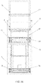
- each structural module (1) is formed by four tubular vertical column (14), one at each corner, interconnected by crossbars equally tubular (15), (16) and (17) forming the lower or ground pavement (2), the intermediate pavement or first floor (3) and the upper level (4), as well as the crossbars (15) and (16) constitute supports for the ends of the rails (7) and (8), while two opposing crossbars (17) form the supports for the locks (5) and further among the four crossbars (15) is located a support plinth (18) for the lifting robot (9).
- each lock (5) is formed by a rectangular tube bar (19) which extends along the corresponding crossbar (17), with which is interconnected by articulated points (20) and, further, by the lower part of each bar (19) there are solidary tips (21) which are hinged together with said bar, the joint is defined at two limited points in a radius of 90 degree, wherein the first said bar (19) stays ( figure 5 ) almost juxtaposed over the corresponding bar (17), while the tips (21) lie horizontally inwardly, while in the second position ( figure 7 ) said bar (19) is displace inwardly and both form a support bracket for the means (31) of the stacked boxes (6) and, further, each bar (19) has two additional center of mass (22) and (23) closely related to the center of the hinged points (20) so that said masses may change the center of gravity of each bar (19) maintaining it by gravity in the locked or unlocked position when it is moved to exceed the vertical center of the hinged points (20).
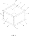
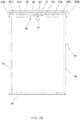
- Each box (6) is a stackable unit, seen in detail in Figures 10 to 12 , where it is verified that each box has at least one open side (24), either upper or lateral, as also each box is formed by structure of square tubes forming an outer frame with an upper framework (25) and an lower framework (26), interconnected by column (27) at the four corners, all of which are combined for receiving closures by inner plates (28) and, further, the upper ends of the column (27) result in conducting fittings (29), while its lower ends have tips (30) which penetrate into the fittings (29) when said box is stacked with other similar units, as also the lower framework of each box (6) is externally contoured by a flap (31) with cuneiform section, the horizontal side (32) being downwardly and the inclined side (33) being the top, wherein the first constitutes point of support of each box (6) over the locks (5) and, further, the ramp part (33) also drives said locks when a box is displaced from the bottom to up.
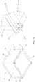
- the rails 7 and 8 are illustrate in detail in figure 14 , where it is seen that they are angle bars positioned in "V” and are also cut in the same format in the crossing points (34).
- the lifting robot (9) is illustrated in detail in Figures 15 to 18 , whereby it is verified that it comprises a first structural part ( Figures 15 and 16 ) defined as structural cage (35), whose height is sufficient to stay adjusted inside of the lower pavement (2) and has internally a driving mechanism (36) for a lifting set (37), movable in the vertical direction as if it were a piston, whose upper part presents compatible sizing to pass through the center of the movement robot (10) to lower or raise the stack of boxes (6) and to place or remove one of them over said movement robot (10), further, the lower part of the structural cage (35) are integrated with the trolley (13) so that the set can be displace in any one of the directions defined by the rails (7).
- a first structural part Figures 15 and 16
- structural cage (35) whose height is sufficient to stay adjusted inside of the lower pavement (2) and has internally a driving mechanism (36) for a lifting set (37), movable in the vertical direction as if it were a piston, whose upper part presents compatible sizing to pass through
- the structural cage (35) is formed by a base (39) sized within the limits defined for support on the support plinth (18), while by the lower side is equipped by a frame of angle bars (40), which also repeat in the upper part forming other framework (41) interconnected with the first by other vertical angle bars (42), one in each corner, further the upper framework (41) receives plates (43) which also repeat over the base (39) and constitute fastening means for the drive mechanism (36) formed by vertical guides (44) and rotating screw shaft equally vertical (45), the latter with their lower ends provided with pulley (46) synchronized by belts (47), however one of them (48), also by means of belt (49), is coupled to another pulley (50) of an electric motor (51) able to rotate in two directions and promoting the simultaneous rotation of all of the screw shaft (45), on which the lifting set (37) is coupled.
- a frame of angle bars (40) which also repeat in the upper part forming other framework (41) interconnected with the first by other vertical angle bars (42), one in each corner, further the upper framework (4
- the lifting set (37) is shown in detail in figure 18 , whereby it is seen that it is formed by a structure defined by two frameworks of angle bars, one lower (52) and one upper (53) interconnected at the four corners by other vertical angle bars (54) and, further, the upper framework (53) includes a lid (55) and thereunder a locking and unlocking mechanism (56) of the locks (5), while the lower framework has plates (57) with smooth holes (58) and threaded holes (59), the first for sliding passage of the vertical guides (44) and the second for the rotating screw shaft (45), said lower framework (52) being positioned between the base (39) and the frame (41) of the structural cage (35), consequently the upper framework (53) and said lid (55) move above said upper frame (41), as well as the four vertical corners (54) of the lifting set (37) pass by interstices (60) existing in the corresponding parts of the structural cage (35).
- the locking and unlocking mechanism (56) is illustrated in detail in Figures 19 and 20 , whereby it is seen that it comprises a servo motor (61) which, together with a central shaft (62), applies half turn in two directions in a disc (63), where the ends of two arms (64) are articulated and eccentrically fitted, whose opposing ends are also pivotally fitted in two radially opposing actuating nozzles (65A), having the distal ends being wedge-shaped (65B) and pierced in the sliding form in supports (65C) fixed under the lid (55), wherein said wedged tips (65B) are exposed or retracted when the servo motor (61) is drive, so that said wedge tips (65B) may perform against the locks (5) in order to move them to the unlocked position during the destacking; the locks (5) return to the locked position during the same descent of the stack by the contact of the flap (31) of the lower box (6) with the hinged tips (21) serving as a support for the box immediately above.
- the flaps (31) of that same box perform against the locks (5) in order to bring them to the unlocked position by releasing the passage and during the descent of the lifting set (37), the tips in wedge (65B) are actuated and act on the hinged tips (21) of the locks in the direction of bringing them into the locked position.
- the lifting robot (9) and the movement robot (10) use the same trolley (13), illustrated in Figures 21 to 25 , where it can be seen that it consists of a structure composed of two frameworks, a upper one of tube (66), and a lower one of parallel flat bars (67), wherein the first presents its corners with receptacles (68) for receiving the tips (30) of the boxes (6), this function only exists in the movement robot (10), but also this first tubular framework (66) is supported and fixed over spacer supports (69) which, in turn, fix the parallel flat bars framework (67) and, at the same time, all spacer supports (69) serve as bearings for the four axles (70), one on each side, synchronized by the ends with the respective conical gears (71), as also one of these axles is driven by motor (72) with pulley (73 and 74) and belt (75) transmission, wherein all the axles (70) configure a transmission for the four running system pairs (76) that are placed below of the parallel flat bars framework (67), where
- the structural module (1) has the first floor (3) provided with waiting supports (98) on which a box (6) is able to be supported by its flap (31) waiting for transport by the movement robot (10).
- the lifting robot (9) is driven so that the first box (6) from bottom to up may be carried to any other point of the installation, thus, the mechanism (36) is driven by moving to up the lift (37) until under the first box (6), where it is released by the unlocked mechanism (56) that drives the locks (5), and then, as shown in Figures 30 and 31 , said lift (37) returns to their original position.
- the locks (5) are again driven by own flaps (31) of the corresponding stackable box (6) so that the upper box or the stack of box (6) may be supported again over the module (1), releasing only the first lower box (6).
- this box is simply placed over the movement robot (10) which, at this stage, is already ready to go in any of the four directions defined in each module, as exemplified in Figures 32 and 33 and, for this purpose, the trolley (13) collects and lowers the corresponding pairs of running system (76) over the corresponding tracks (8).
- the box (6) may be downwardly moved by the lifting robot (9) and be rested on the waiting supports (98).
- the movement robot does not have to be present in this module, it may be working in other modules and, at the desired opportunity, this waiting box is gathered by the movement robot (10) to be taken up to any another module.
- the running systems (76) move in pairs to up and down, such movement allows that the waiting box (6) to be raised and lowered only the sufficient to be withdrawn or placed over the waiting supports (98).
- Such operation allows many boxes to be moved from one side to another and placed in corresponding waiting supports (98). This operating condition allows the boxes (6) to be moved from one modulo to the other without the presence of the lifting robot (9).
- the waiting supports (98) allows that the two robots working independently, which further increases the possibilities of movement of the boxes among the modules.
- All the drives are managed by specific software, with different sensors being provided in the corresponding parts and other electronic components, mainly those for wi-fi network, not illustrated, since the object of the invention is a module capable of allowing the assembly of small, medium and large installations, consequently, there are large variations in the use of hardware and software.
- a method for storage by stacking and handling of boxes to be carried out by an installation obtained according with the modular structure previously described comprising the basic steps of:
Landscapes
- Engineering & Computer Science (AREA)
- Mechanical Engineering (AREA)
- Theoretical Computer Science (AREA)
- Physics & Mathematics (AREA)
- Data Mining & Analysis (AREA)
- Molecular Biology (AREA)
- Artificial Intelligence (AREA)
- Biomedical Technology (AREA)
- Biophysics (AREA)
- Computational Linguistics (AREA)
- Health & Medical Sciences (AREA)
- Evolutionary Computation (AREA)
- General Health & Medical Sciences (AREA)
- Life Sciences & Earth Sciences (AREA)
- Computing Systems (AREA)
- General Engineering & Computer Science (AREA)
- General Physics & Mathematics (AREA)
- Mathematical Physics (AREA)
- Software Systems (AREA)
- Robotics (AREA)
- Warehouses Or Storage Devices (AREA)
- Stacking Of Articles And Auxiliary Devices (AREA)
Claims (12)
- Modularer Sockel zur Zusammenstellung einer Anlage zur Lagerung durch Stapeln und Handhaben von Kisten, bestehend aus:- einem strukturellen Modul (1), mit Parallelepiped Format und vertikal länglich, mit einer quadratischen oder rechteckigen Grundfläche mit drei funktionellen Abschnitten entlang seiner Höhe, die echte Stockwerten darstellen, wobei ein unteres Stockwerk als Erdgeschoss definiert ist (2), ein Zwischenpflaster, das als erster Stock definiert ist (3) und ein oberer Belag, der als Stützebene definiert ist (4);- die Stützebene (4) mit zwei gegenüberliegenden Rändern, die mit Stützsperren (5) für gestapelte Kisten ausgestattet sind (6);- das Erdgeschoss (2) und der erste Stock (3) sind jeweils zu gleichen Teilen mit vier Schienensegmenten versehen (7) und (8);- mindestens einen Hubroboter (9) der auf den Schienen (7) des Erdgeschosses arbeitet (2);- mindestens einen Bewegungsroboter (10) der auf den Schienen (8) des ersten Stockwerks arbeitet (3);- das genannte Strukturmodul kann (1) mit anderen gleichen Einheiten, die an allen oder einer seiner vier Seiten angepasst sind, zusammengefügt werden, wobei diese Kombination auch mit der Ausrichtung zwischen allen Schienen zusammenfällt (7) und (8) durch die Schaffung von Wegen in den vier Richtungen jedes strukturellen Moduls, die Routen für die Roboter darstellen (9 und 10);- Kisten, (6) so bemessen, dass sie ohne Schwierigkeiten von der Unterstützungsebene (4) zum ersten Stock durchlaufen können, (3) und um von dem Bewegungsroboter getragen zu werden; (10);- der Hubroboter (9) präsentiert Mittel (11,37) frei durch das Zentrum des Bewegungsroboters zu gehen (10) und das Absenken und Anheben des Kistenstapels zu durchführen (6);- die Kisten (6) haben Mittel (12) für den automatischen Antrieb der Riegel (5), geeignet zum Freigeben des Kistenstapels (6) während des Moments der vertikalen Bewegung;- der Hubroboter (9) und der Bewegungsroboter (10) sind ebenfalls mit einem Wagen ausgestattet (13) mit einem Laufsystem auf vier Seiten, die alle auf- und abwärts beweglich und so geeignet sind, dass das Laufsystem von zwei gegenüberliegenden Seiten in der Schwebe bleibt, während die anderen über die entsprechenden Schienen gelegt werden (7 oder 8), so dass diese Bewegung eine Richtungsänderung von 90 Grad ermöglicht, so dass die Roboter (9 und 10) sich über diese Schienen bewegen können (7 und 8) nach jeder gewünschten Route.
- Modulare Basis zum Zusammenstellen einer Anlage zur Lagerung durch Stapeln und Handhaben von Kisten nach Anspruch 1, wobei jedes Strukturmodul (1) von vier röhrenförmigen vertikalen Säulen gebildet wird, (14), einer an jeder Ecke, verbunden durch Querstäbe, die ebenfalls rohrförmig sind (15,16,17) die das Erdgeschoss (2), den ersten Stock (3) und die Unterstützungsebene bilden, (4)und die Querbalken (15,16) bilden Stützen für die Schienenenden (7,8), während zwei gegenüberliegende Querbalken (17) die Stützen für die Riegel bilden (5) und weiter unter den vier Querbalken (15) befindet sich ein Stützsockel (18) für den Hubroboter (9).
- Modulare Basis zum Zusammenstellen einer Anlage zur Lagerung durch Stapeln und Handhaben von Kisten nach Anspruch 2, wobei jeder Riegel (5) durch eine rechteckige Rohrstange gebildet wird, (19) die sich entlang der entsprechenden Querstange erstreckt (17)mit dem sie durch Scharnierpunkte verbunden ist (20) und, weiter, durch den unteren Teil jedes Rohrstabs (19) gibt es solidarische Spitzen (21) die mit dieser Rohrstange gelenkig verbunden sind (19)wobei diese Verbindung an zwei begrenzten Punkten in einem Radius von 90 Grad definiert ist, wobei in der ersten Position die besagte Rohrstange (19) über dem entsprechenden Querbalken nebeneinander liegt (17), während die Spitzen (21) horizontal nach innen liegen, während in der zweiten Position die Rohrstange (19) nach innen verlagert ist und Beide eine Stütze für die Mittel (12) des automatischen Antriebs der Riegel (5) der gestapelten Schachteln bilden, (6) und, weiter, jede Rohrstange (19) zwei zusätzliche Massenzentren hat, (22,23) eng mit dem Zentrum der Gelenkpunkte verbunden (20) damit besagte Massen (22,23) den Schwerpunkt jeder Rohrstange verändern, (19) und diese in verriegelter oder entriegelter Stellung halten können, wenn sie über die vertikale Mitte der Gelenkpunkte hinaus bewegt wird (20).
- Modulare Basis für eine Zusammensetzungsanlage zur Lagerung durch Stapeln und Handhaben von Kisten nach Anspruch 1, wobei jede Kiste (6) eine stapelbare Einheit ist und mindestens eine offene Seite (24)entweder oben oder seitlich hat, da auch jede Kiste durch eine Struktur aus quadratischen Rohren gebildet wird, die einen äußeren Rahmen mit einem oberen Rahmen (25) und einem niedrigeren Rahmen bilden (26), durch Säulen an den vier Ecken, (27) miteinander verbunden, die Alle zur Aufnahme von Verschlüssen durch Innenplatten zusammengefasst sind (28) und ferner führen die oberen Enden der Säulen (27) zu leitfähigen Armaturen (29), während deren unteren Enden Spitzen haben (30) die in die Armaturen eindringen (29) wenn diese Kiste mit anderen ähnlichen Einheiten gestapelt wird, wie auch der untere Rahmen (26) jeder Box (6) außen durch eine Klappe konturiert ist (31) mit keilförmigem Abschnitt, die horizontale Seite (32) nach unten und die geneigte Seite (33) nach oben, wobei der erste den Auflagepunkt jedes Kastens (6) über die Riegel bietet, (5) und, weiter, die geneigte Seite (33) auch die besagten Riegel antreibt (5) wenn eine Kiste von unten nach oben verschoben wird.
- Modulare Basis für eine zusammensetzbare Anlage zur Lagerung durch Stapeln und Handhaben von Kisten nach Anspruch 1, wobei die Schienen (7,8) in "V" positionierte Winkelbalken sind, die in Kreuzungspunkten ebenfalls im gleichen Format geschnitten sind (34).
- Modulare Basis für eine Zusammensetzungsanlage zur Lagerung durch Stapeln und Handhaben von Kisten nach Anspruch 1, wobei der Hubroboter (9) aus einem ersten strukturellen Teil, dem strukturellen Käfig (35), dessen Höhe ausreicht, um innerhalb des Erdgeschosses eingestellt zu bleiben, gebildet ist (2) und innerseits einen Antriebsmechanismus (36) für einen Hebesatz hat, (37), Der in vertikaler Richtung wie ein Kolben beweglich ist, dessen oberer Teil eine kompatible Größe aufweist, um das Zentrum des Bewegungsroboters zu überfahren (10) zum Absenken oder Anheben des Kistenstapels (6) und einen von ihnen über dem Bewegungsroboter zu platzieren oder zu entfernen (10), weiter ist der untere Teil des strukturellen Käfigs (35) mit dem Wagen (13) des Hubroboters integriert (9) so dass der Stapel in jede der durch die Schienen definierten Richtungen verschoben werden kann (7).
- Modulare Basis für eine zusammensetzbare Anlage zur Lagerung durch Stapeln und Handhaben von Kisten nach Anspruch 6, wobei der strukturelle Käfig (35) durch eine Basis gebildet wird, (39) die innerhalb der für die Abstützung auf dem Tragsockel definierten Grenzen dimensioniert ist, (18), während an der Unterseite der strukturelle Käfig (35) mit einem Rahmen aus Winkelstangen ausgestattet ist (40), die sich auch im oberen Teil des strukturellen Käfigs wiederholen (35) und einen oberen Rahmen bilden (41) Der mit dem Rahmen aus Winkelstangen (40) durch andere vertikale Winkelbalken verbunden ist, (42), einer in jeder Ecke, ferner empfängt der obere Rahmen (41) Platten (43) die sich auch über die Basis wiederholen (39) und stellen Befestigungsmittel für den Antriebsmechanismus dar (36) gebildet durch vertikale Führungen (44) und rotierende Schneckenwellen (45) ebenso vertikal, die rotierenden Schneckenwellen (45) sind an ihren unteren Enden mit Riemenscheiben versehen (46,48) die durch Riemen synchronisiert sind, (47), jedoch ist eine der Riemenscheiben (48)auch mit Hilfe eines Riemens, (49)mit einer anderen Riemenscheibe (50) eines Elektromotors gekuppelt, (51) die sich in zwei Richtungen drehen kann und die gleichzeitige Drehung aller Schneckenwellen fördert (45), an der die Hebevorrichtung (37) gekoppelt ist.
- Modulare Basis für eine zusammensetzbare Anlage zur Lagerung durch Stapeln und Handhaben von Kisten nach Anspruch 7, wobei der Hebesatz (37) durch eine Struktur gebildet wird, die durch zwei Rahmen aus Winkelstangen definiert ist, ein unterer Rahmen (52) und ein oberer Rahmen (53) an den vier Ecken durch weitere vertikale Winkelstäbe miteinander verbunden (54) und, weiterhin enthält der obere Rahmen (53) einen Deckel (55) und darunter einen Ver- und Entriegelungsmechanismus (56) der Riegel, (5)während der untere Rahmen (52) Platten (57) mit glatten Löchern (58) und Gewindebohrungen hat (59), die erste für den gleitenden Durchgang der vertikalen Führungen (44) und die zweite für die rotierenden Schneckenwellen (45), besagter unterer Rahmen (52) Ist zwischen der Basis (39) und de, oberen Rahmen (41) des strukturellen Käfigs positioniert (35), folglich bewegen sich der obere Rahmen (53) und besagter Deckel (55) des Hebesatzes (37) über den genannten oberen Rahmen (41) des strukturellen Käfigs (35), und die vier vertikalen Ecken (54) des Hebesatzes (37) gehen an Zwischenräumen vorbei, (60) die in den entsprechenden Teilen des strukturellen Käfigs vorhanden sind (35).
- 9. Modulare Basis für eine zusammensetzbare Anlage zur Lagerung durch Stapeln und Handhaben von Kisten nach den Ansprüchen 3, 4 und 8, wobei der Verriegelungs- und Entriegelungsmechanismus (56) einen Servomotor umfasst, (61) der zusammen mit einer zentralen Welle (62), eine halbe Umdrehung in zwei Richtungen auf eine Scheibe anwendet (63)wo die Enden von zwei Armen (64) gelenkig und exzentrisch gelagert sind, deren gegenüberliegende Enden ebenfalls in zwei radial gegenüberliegenden Betätigungsdüsen schwenkbar gelagert sind (65A), wobei die distalen Enden keilförmig sind (65B) und in der Gleitform in Stützen (65C) die unter dem Deckel befestigt sind, durchbohrt sind (55), wobei die keilförmigen Enden (65B) aus- oder eingefahren werden, wenn der Servomotor (61) Angetrieben wird, so dass die keilförmigen Enden (65B) gegen die Sperren durchführen dürfen (5) um sie während des Abstapelns in die entriegelte Position zu bringen; die Riegel (5) kehren während desselben Absenkens des Stapels in die verriegelte Position zurück, durch den Kontakt der Klappe (31) des unteren Kastens (6) mit den Spitzen (21) der Riegel (5) die als Stütze für die Box unmittelbar darüber dient, wobei während des Stapelns einer neuen Kiste die Klappen (31) derselben Kiste gegen die Riegel stoßen (5) um sie durch Freigabe des Durchgangs und während des Absenkens des Hebesatzes in die entriegelte Stellung zu bringen (37)die keilförmigen Enden (65B) werden betätigt und wirken auf die Spitzen (21) der Riegel (5) in der Richtung, sie in die Sperrposition zu bringen.
- Modulare Basis für eine zusammensetzbare Anlage zur Lagerung durch Stapeln und Handhaben von Kisten nach Anspruch 1, der Hubroboter (9) Und der Bewegungsroboter (10) verwenden dieselben Wagen (13)wobei jeder Wagen (13) eine Struktur die aus zwei Rahmen besteht, enthält, einen aus Rohren gebildeten oberen Rahmen (66), Und einen unteren Rahmen aus parallelen Flachstäben (67)wobei der Erste Aufnahmebehälter in seinen Ecken vorweist (68) um die Spitzen (30) Der Kisten (6), diese Funktion besteht nur in dem Bewegungsroboter (10), Aber dieser oberer Rahmen (66) Ist auch von abstandhaltenden Stützen gestützt und über diesen angebracht (69) die, ihrerseits, den aus parallelen Flachstäben bestehenden unteren Ramen befestigen (67) Und, gleichzeitig, dienen alle abstandhaltenden Stützen (69) Als Kugelllager für vier Achsen, (70), eines auf jeder Seite, synchronisiert durch die Enden mit entsprechenden konischen Zahnrädern (71)als auch eine dieser Achsen (70) von einem ersten Motor angetrieben wird, (72) mit Übertragung durch Riemenscheibe (73, 74) und Gürtel (75), wobei alle Achsen (70) eine Übertragung für die vier laufenden Systempaare konfigurieren (76) die sich unterhalb des unteren Rahmens aus parallelen Flachstäben (67) befinden, wobei jedes Laufsystem, außer dass es sehr nahe an jeder Ecke des Satzes bleibt, seinen eigenen Antriebsmechanismus hat, der zwischen den parallelen Flachstangen des unteren Rahmens montiert (67) ist, Jeder Mechanismus besteht aus einen Antriebsblock, (77) in der Gleitform in Führungen montiert (78) und einer Schraubenwelle (79), mit Anschlägen (80) die mitgeliefert werden, wobei die gesamte Garnitur zwischen den parallelen Flachstäben des unteren Rahmens montiert wird (67), während die Schneckenwelle (79) mit einem Ende an eine entsprechende Achse gekoppelt ist (70) mittels einer Übertragung (81) von Riemenscheiben und Bändern, während am entgegengesetzten Ende der Schraubenwelle (79) der Antriebsblock (77) gelenkig (82) mit einem pantographischen Träger gekoppelt ist, der durch eine erste Gabel definiert ist (83), in der der mittlere Teil der ersten Gabel (83) gelenkig (84) zum unteren Ende einer zweiten Gabel (85)gekoppelt ist, dessen oberes Ende ebenfalls gelenkig (86) zu den parallelen Flachstäben des unteren Rahmens (67)Gekoppelt ist, und in derselben Koppelachse (86) des oberen Endes der zweiten Gabel (85) zu den parallelen Flachstäben des unteren Rahmens (67),gibt es eine erste doppelte Zwischenscheibe (87) die durch das erste Band (88) an eine Riemenscheibe (89) eines zweiten Motors (90) gekoppelt ist, und mit Hilfe eines zweiten Bandes (91) mit einer zweiten doppelten Zwischenscheibe gekoppelt ist, (92) die in der Koppelachse (84) des mittleren Teils der ersten Gabelung (83) zum unteren Ende der zweiten Gabel (85), am unteren Ende der ersten Gabel (83) ist ein Rad in Form einer Doppelriemenscheibe montiert, (93), mit zwei Bändern (94,95)wobei das erste an die zweite doppelte Zwischenscheibe gekoppelt ist (92) während das zweite mit dem anderen Rad in Form einer doppelten Riemenscheibe von der gleichen Seite (93) gekoppelt ist, wobei die Kraft des zweiten Motors (90) auf die anderen Seiten mit anderen Riemenschreiben übertragen wird, die auf die gleiche Weise angeordnet sind, aber eine überträgt die Bewegung auf eine andere durch Umlenkungen der Ecken (96) und entsprechenden Bändern (97).
- Modulare Basis zum Zusammenstellen einer Anlage zu dem Stapeln und Handhaben von Kisten nach Anspruch 6, wobei das Strukturmodul (1) den ersten Stock hat, (3) mit wartenden Stützen versehen (98) auf dem eine Kiste (6) durch ihre Klappe gestützt werden kann (31) Während sie auf den Transport durch den Bewegungsroboter (10)wartet.
- Verfahren zum Lagern durch Stapeln und Handhaben von Kisten, das von einer Anlage durchgeführt werden soll, die gemäß der in Anspruch 11 beschriebenen modularen Struktur erhalten wird, die folgenden Grundschritte umfassend:- nebeneinander Kombination mehrerer struktureller Module (1) für die Konfiguration einer kompletten Anlage, die eine Struktur mit drei funktionellen Stockwerken bildet, wobei das Unterste als Erdgeschoss bezeichnet wird (2)ein Zwischenpflaster, das als erster Stock definiert ist (3) und ein oberer Belag, der als Stützebene definiert ist (4), letztere stellt einen Auflagepunkt für einen oder mehrere gestapelte Kisten dar (6), während die beiden anderen Stockwerke (2,3) die von den Schienen gebildeten Fortbewegungswege, jeweils (7,8) zum Hubroboter (9) und Bewegungsroboter (10)enthalten;- der Eingang der Kisten (6) in die Einrichtung erfolgt vom ersten Stockwerk aus (3) an einem beliebigen Punkt des durch die Zusammenstellung gebildeten Umfangs, wobei jede Kiste zunächst auf dem Bewegungsroboter positioniert wird (10) der zuvor im entsprechenden Modul positioniert wurde, (1), und wird dann von diesem Roboter gemäß einer softwaredefinierten Route bis zu einem anderen Punkt der Anlage bewegt, dessen Ziel die Kiste (6) auf zwei verschiedene Arten erhält: a) Die Kiste wird einfach auf die wartenden Stützen gelegt (98) unter Freigabe des Bewegungsroboters für neue Aufgaben und, im geeigneten Moment und durch die Software definiert, wird diese Kiste durch den Hubroboter nach oben bewegt (9) und auf die Unterstützungsebene gestellt (4); b) Software synchronisiert die Ankunft des Bewegungsroboters (10) mit einer Kiste beladen (6) und der Hubroboter (9) und, letzterer führt die Platzierung der Kiste auf der Stützebene durch (4) im Moment, in dem die Riegel (5) angetrieben werden, um die Positionierung der Kiste oder deren Stapelung mit anderen vorhandenen Einheiten im selben Modul abzuschließen (1); und- die Neuanordnung der gestapelten Kisten (6) wird: a) unabhängig vom Bewegungsroboter durchgeführt, (10), der Hubroboter (9) führt die Abstapelung der Kisten durch (6) indem er sie nacheinander bis zu den wartenden Stützen bringt (98); b) die in den wartenden Stützen gehaltenen (98) Kisten (6) werden nur durch den Bewegungsroboter (10) in die anderen Module verlagert (10); c) die in den wartenden Stützen (98) Gehaltenen Kisten (6) werden durch den Hubroboter gestapelt (9) unabhängig von der Position, die der Bewegungsroboter einnimmt (10); d) die beiden Roboter sind bis zum gleichen Modulo synchronisiert, um das Abstapeln oder Stapeln eines Kartons durchzuführen (6).
Applications Claiming Priority (2)
| Application Number | Priority Date | Filing Date | Title |
|---|---|---|---|
| BR102014023154-4A BR102014023154B1 (pt) | 2014-09-18 | 2014-09-18 | Base modular para compor instalações e método para estocagem por empilhamento e movimentação de caixas |
| PCT/BR2015/000142 WO2016041035A1 (pt) | 2014-09-18 | 2015-09-17 | Basε modular para compor instalações e método para estocagem por empilhamento e movimentação de caixas |
Publications (3)
| Publication Number | Publication Date |
|---|---|
| EP3196152A1 EP3196152A1 (de) | 2017-07-26 |
| EP3196152A4 EP3196152A4 (de) | 2018-05-30 |
| EP3196152B1 true EP3196152B1 (de) | 2021-01-27 |
Family
ID=55532356
Family Applications (1)
| Application Number | Title | Priority Date | Filing Date |
|---|---|---|---|
| EP15842436.6A Active EP3196152B1 (de) | 2014-09-18 | 2015-09-17 | Modularer sockel zur herstellung von installationen und verfahren zur lagerung mittels stapelung und bewegung von kästen |
Country Status (5)
| Country | Link |
|---|---|
| US (1) | US10479602B2 (de) |
| EP (1) | EP3196152B1 (de) |
| AU (1) | AU2015318768B2 (de) |
| BR (1) | BR102014023154B1 (de) |
| WO (1) | WO2016041035A1 (de) |
Families Citing this family (7)
| Publication number | Priority date | Publication date | Assignee | Title |
|---|---|---|---|---|
| NO347820B1 (en) * | 2018-01-09 | 2024-04-08 | Autostore Tech As | Automated storage and retrieval system, a container handling vehicle which can operate on an automated storage and retrieval system and a method of operating an automated storage and retrieval system |
| DE102018215780A1 (de) * | 2018-09-18 | 2020-03-19 | Robert Bosch Gmbh | Vorrichtung und Verfahren zum Handhaben von Lagereinheiten |
| EP3946834B1 (de) * | 2019-03-27 | 2024-01-10 | Boston Dynamics, Inc. | Roboter und verfahren zum palettieren von schachteln |
| CN110510307B (zh) * | 2019-06-28 | 2024-08-09 | 江苏迅捷智能科技有限公司 | 一种取放装置及档案管理系统 |
| AT522334B1 (de) * | 2019-08-13 | 2020-10-15 | Knapp Ag | Schienenkreuzung für ein Regallager |
| EP3782929A1 (de) * | 2019-08-23 | 2021-02-24 | Jungheinrich Aktiengesellschaft | Behälterstapellager-beschickungswagen |
| CN113387088B (zh) * | 2020-03-11 | 2022-11-25 | 财团法人精密机械研究发展中心 | 仓储模块、仓储货架及仓储系统 |
Family Cites Families (23)
| Publication number | Priority date | Publication date | Assignee | Title |
|---|---|---|---|---|
| US2701065A (en) | 1950-09-06 | 1955-02-01 | Charles A Bertel | Apparatus for storing and handling containers |
| US3964619A (en) * | 1972-03-13 | 1976-06-22 | Felix Irmler | Arrangement for storage of goods in packages in an upright depository |
| US4007843A (en) | 1972-07-17 | 1977-02-15 | Rapistan, Incorporated | Multi-aisle warehouse system with mobile lift having control means for an article transfer vehicle |
| US4415975A (en) | 1980-12-31 | 1983-11-15 | Mid-West Conveyor Company, Inc. | Apparatus and method for rough positioning a vehicle at a storage bin in an automatic storage and retrieval system |
| US5314285A (en) * | 1993-01-13 | 1994-05-24 | Necer International Co., Ltd. | Automatic controlled multi-level storage system |
| FI105668B (fi) | 1995-10-02 | 2000-09-29 | Cimcorp Oy | Poimintajärjestelmä |
| NO972004D0 (no) | 1997-04-30 | 1997-04-30 | Hatteland Electronic As Jacob | Metode for organisering av vareflyt for en horisontalt lagdelt og dypstablet lagerbeholdning med uensartede komponenter, samt forflytningsutstyr for standariserte beholdere til formålet |
| FI108346B (fi) | 1998-07-07 | 2002-01-15 | Sunds Defibrator Panelhandling | Laitteisto levynippujen kõsittelemiseksi |
| JP2000044010A (ja) * | 1998-07-30 | 2000-02-15 | Amada Co Ltd | 自動倉庫システム |
| US20070276535A1 (en) | 1999-07-30 | 2007-11-29 | Gerhard Haag | Automated warehouse facility |
| US20030228208A1 (en) * | 2000-05-25 | 2003-12-11 | Grond Johann W. | Vertical conveyor and vertical conveyor system |
| US6974293B2 (en) * | 2001-06-25 | 2005-12-13 | Van Stokes | Material handling assembly |
| US20060018738A1 (en) * | 2004-07-06 | 2006-01-26 | Tai-Chun Yen | Parking tower |
| JP2008195503A (ja) * | 2007-02-14 | 2008-08-28 | Daifuku Co Ltd | 物品搬送装置 |
| JP5093843B2 (ja) | 2007-08-09 | 2012-12-12 | 野場電工株式会社 | 容器積載装置 |
| FI123447B (fi) | 2011-03-18 | 2013-05-15 | Cimcorp Oy | Siltarobottijärjestelmä ja menetelmä sen käyttämiseksi |
| ITBG20110011U1 (it) | 2011-03-21 | 2012-09-22 | Automha S R L | Impianto automatico di stoccaggio. |
| ES2890505T5 (en) * | 2012-05-11 | 2025-03-11 | Ocado Innovation Ltd | Storage systems and methods for retrieving units from a storage system |
| US20140086714A1 (en) | 2012-09-27 | 2014-03-27 | Ohad MALIK | Automated warehousing systems and method |
| KR20140066529A (ko) | 2012-11-23 | 2014-06-02 | 대림스타릿 주식회사 | 염료의 연속계량장치법 |
| KR20140072239A (ko) | 2012-11-27 | 2014-06-13 | 에스티엑스조선해양 주식회사 | 선박용 강재 타워식 적치장치 |
| NO335839B1 (no) | 2012-12-10 | 2015-03-02 | Jakob Hatteland Logistics As | Robot for transport av lagringsbeholdere |
| DE202014102274U1 (de) | 2014-05-14 | 2014-06-16 | SSI Schäfer AG | Folienerkennung und Palettentyperkennung mittels Kanalfahrzeug in einem Kanalregallager |
-
2014
- 2014-09-18 BR BR102014023154-4A patent/BR102014023154B1/pt not_active IP Right Cessation
-
2015
- 2015-09-17 US US15/511,230 patent/US10479602B2/en not_active Expired - Fee Related
- 2015-09-17 WO PCT/BR2015/000142 patent/WO2016041035A1/pt not_active Ceased
- 2015-09-17 AU AU2015318768A patent/AU2015318768B2/en not_active Ceased
- 2015-09-17 EP EP15842436.6A patent/EP3196152B1/de active Active
Non-Patent Citations (1)
| Title |
|---|
| None * |
Also Published As
| Publication number | Publication date |
|---|---|
| US10479602B2 (en) | 2019-11-19 |
| US20170313513A1 (en) | 2017-11-02 |
| BR102014023154B1 (pt) | 2022-03-29 |
| BR102014023154A2 (pt) | 2016-04-19 |
| EP3196152A1 (de) | 2017-07-26 |
| AU2015318768A1 (en) | 2017-05-04 |
| WO2016041035A1 (pt) | 2016-03-24 |
| AU2015318768B2 (en) | 2020-05-28 |
| EP3196152A4 (de) | 2018-05-30 |
Similar Documents
| Publication | Publication Date | Title |
|---|---|---|
| EP3196152B1 (de) | Modularer sockel zur herstellung von installationen und verfahren zur lagerung mittels stapelung und bewegung von kästen | |
| US12006149B2 (en) | Storage and retrieval system | |
| KR102663009B1 (ko) | 모듈형 보관 시스템 및 방법 | |
| EP4183720B1 (de) | Verfahren und abgabestation zur verteilung von waren | |
| KR102538516B1 (ko) | 물품을 피킹하는 시스템 및 방법 | |
| JP7726906B2 (ja) | 複数の行を伴う自動保管タワー | |
| CA3191324A1 (en) | A grid framework structure | |
| JP2023526122A (ja) | 荷積みおよび/または荷下ろし可能なコンテナ取り扱い車両 | |
| EP3341307B1 (de) | Verfahren sowie lager- und kommissioniersystem zum vollautomatisierten kommissionieren von lagereinheiten | |
| FI13198Y1 (fi) | Ristikkorunkorakenne | |
| JP7813237B2 (ja) | 自動保管および回収システム | |
| EP4359175B1 (de) | System und verfahren zum kommissionieren von flatpack-artikeln | |
| JP2026015386A (ja) | 第1及び第2のシャッタを伴う車両ゲート配列、配列を備えるシステム、及び動作方法 | |
| EP3909894A1 (de) | Einrichtung, system und verfahren zur lagerung und kommissionierung von gegenständen | |
| JP2025517493A (ja) | 多温度保管システム | |
| EP4359324A1 (de) | System und verfahren zum kommissionieren von flatpack-artikeln | |
| NL2033022B1 (en) | Storage system | |
| NO348001B1 (en) | A container transport vehicle, an automated storage and retrieval system and a method thereof | |
| HK40078988B (zh) | 多行自动存储塔 | |
| JPH06294236A (ja) | 立体駐車設備 |
Legal Events
| Date | Code | Title | Description |
|---|---|---|---|
| STAA | Information on the status of an ep patent application or granted ep patent |
Free format text: STATUS: THE INTERNATIONAL PUBLICATION HAS BEEN MADE |
|
| PUAI | Public reference made under article 153(3) epc to a published international application that has entered the european phase |
Free format text: ORIGINAL CODE: 0009012 |
|
| STAA | Information on the status of an ep patent application or granted ep patent |
Free format text: STATUS: REQUEST FOR EXAMINATION WAS MADE |
|
| 17P | Request for examination filed |
Effective date: 20170406 |
|
| AK | Designated contracting states |
Kind code of ref document: A1 Designated state(s): AL AT BE BG CH CY CZ DE DK EE ES FI FR GB GR HR HU IE IS IT LI LT LU LV MC MK MT NL NO PL PT RO RS SE SI SK SM TR |
|
| AX | Request for extension of the european patent |
Extension state: BA ME |
|
| DAV | Request for validation of the european patent (deleted) | ||
| DAX | Request for extension of the european patent (deleted) | ||
| REG | Reference to a national code |
Ref country code: DE Ref legal event code: R079 Ref document number: 602015065313 Country of ref document: DE Free format text: PREVIOUS MAIN CLASS: B65G0001060000 Ipc: B65G0001040000 |
|
| A4 | Supplementary search report drawn up and despatched |
Effective date: 20180502 |
|
| RIC1 | Information provided on ipc code assigned before grant |
Ipc: B65G 1/04 20060101AFI20180424BHEP |
|
| GRAP | Despatch of communication of intention to grant a patent |
Free format text: ORIGINAL CODE: EPIDOSNIGR1 |
|
| STAA | Information on the status of an ep patent application or granted ep patent |
Free format text: STATUS: GRANT OF PATENT IS INTENDED |
|
| INTG | Intention to grant announced |
Effective date: 20200915 |
|
| GRAS | Grant fee paid |
Free format text: ORIGINAL CODE: EPIDOSNIGR3 |
|
| GRAA | (expected) grant |
Free format text: ORIGINAL CODE: 0009210 |
|
| STAA | Information on the status of an ep patent application or granted ep patent |
Free format text: STATUS: THE PATENT HAS BEEN GRANTED |
|
| AK | Designated contracting states |
Kind code of ref document: B1 Designated state(s): AL AT BE BG CH CY CZ DE DK EE ES FI FR GB GR HR HU IE IS IT LI LT LU LV MC MK MT NL NO PL PT RO RS SE SI SK SM TR |
|
| REG | Reference to a national code |
Ref country code: GB Ref legal event code: FG4D |
|
| REG | Reference to a national code |
Ref country code: CH Ref legal event code: EP |
|
| REG | Reference to a national code |
Ref country code: AT Ref legal event code: REF Ref document number: 1358174 Country of ref document: AT Kind code of ref document: T Effective date: 20210215 |
|
| REG | Reference to a national code |
Ref country code: IE Ref legal event code: FG4D |
|
| REG | Reference to a national code |
Ref country code: DE Ref legal event code: R096 Ref document number: 602015065313 Country of ref document: DE |
|
| REG | Reference to a national code |
Ref country code: DE Ref legal event code: R081 Ref document number: 602015065313 Country of ref document: DE Owner name: CIFELLI, CARMINE ALEXANDRE, BR Free format text: FORMER OWNER: CIFELLI, CARMINE, SAO PAULO, BR |
|
| REG | Reference to a national code |
Ref country code: CH Ref legal event code: NV Representative=s name: TR-IP CONSULTING LLC, CH |
|
| REG | Reference to a national code |
Ref country code: NL Ref legal event code: MP Effective date: 20210127 |
|
| REG | Reference to a national code |
Ref country code: LT Ref legal event code: MG9D |
|
| REG | Reference to a national code |
Ref country code: AT Ref legal event code: MK05 Ref document number: 1358174 Country of ref document: AT Kind code of ref document: T Effective date: 20210127 |
|
| PG25 | Lapsed in a contracting state [announced via postgrant information from national office to epo] |
Ref country code: HR Free format text: LAPSE BECAUSE OF FAILURE TO SUBMIT A TRANSLATION OF THE DESCRIPTION OR TO PAY THE FEE WITHIN THE PRESCRIBED TIME-LIMIT Effective date: 20210127 Ref country code: GR Free format text: LAPSE BECAUSE OF FAILURE TO SUBMIT A TRANSLATION OF THE DESCRIPTION OR TO PAY THE FEE WITHIN THE PRESCRIBED TIME-LIMIT Effective date: 20210428 Ref country code: FI Free format text: LAPSE BECAUSE OF FAILURE TO SUBMIT A TRANSLATION OF THE DESCRIPTION OR TO PAY THE FEE WITHIN THE PRESCRIBED TIME-LIMIT Effective date: 20210127 Ref country code: NL Free format text: LAPSE BECAUSE OF FAILURE TO SUBMIT A TRANSLATION OF THE DESCRIPTION OR TO PAY THE FEE WITHIN THE PRESCRIBED TIME-LIMIT Effective date: 20210127 Ref country code: BG Free format text: LAPSE BECAUSE OF FAILURE TO SUBMIT A TRANSLATION OF THE DESCRIPTION OR TO PAY THE FEE WITHIN THE PRESCRIBED TIME-LIMIT Effective date: 20210427 Ref country code: LT Free format text: LAPSE BECAUSE OF FAILURE TO SUBMIT A TRANSLATION OF THE DESCRIPTION OR TO PAY THE FEE WITHIN THE PRESCRIBED TIME-LIMIT Effective date: 20210127 Ref country code: PT Free format text: LAPSE BECAUSE OF FAILURE TO SUBMIT A TRANSLATION OF THE DESCRIPTION OR TO PAY THE FEE WITHIN THE PRESCRIBED TIME-LIMIT Effective date: 20210527 Ref country code: NO Free format text: LAPSE BECAUSE OF FAILURE TO SUBMIT A TRANSLATION OF THE DESCRIPTION OR TO PAY THE FEE WITHIN THE PRESCRIBED TIME-LIMIT Effective date: 20210427 |
|
| PG25 | Lapsed in a contracting state [announced via postgrant information from national office to epo] |
Ref country code: SE Free format text: LAPSE BECAUSE OF FAILURE TO SUBMIT A TRANSLATION OF THE DESCRIPTION OR TO PAY THE FEE WITHIN THE PRESCRIBED TIME-LIMIT Effective date: 20210127 Ref country code: LV Free format text: LAPSE BECAUSE OF FAILURE TO SUBMIT A TRANSLATION OF THE DESCRIPTION OR TO PAY THE FEE WITHIN THE PRESCRIBED TIME-LIMIT Effective date: 20210127 Ref country code: PL Free format text: LAPSE BECAUSE OF FAILURE TO SUBMIT A TRANSLATION OF THE DESCRIPTION OR TO PAY THE FEE WITHIN THE PRESCRIBED TIME-LIMIT Effective date: 20210127 Ref country code: RS Free format text: LAPSE BECAUSE OF FAILURE TO SUBMIT A TRANSLATION OF THE DESCRIPTION OR TO PAY THE FEE WITHIN THE PRESCRIBED TIME-LIMIT Effective date: 20210127 Ref country code: AT Free format text: LAPSE BECAUSE OF FAILURE TO SUBMIT A TRANSLATION OF THE DESCRIPTION OR TO PAY THE FEE WITHIN THE PRESCRIBED TIME-LIMIT Effective date: 20210127 |
|
| PG25 | Lapsed in a contracting state [announced via postgrant information from national office to epo] |
Ref country code: IS Free format text: LAPSE BECAUSE OF FAILURE TO SUBMIT A TRANSLATION OF THE DESCRIPTION OR TO PAY THE FEE WITHIN THE PRESCRIBED TIME-LIMIT Effective date: 20210527 |
|
| REG | Reference to a national code |
Ref country code: DE Ref legal event code: R097 Ref document number: 602015065313 Country of ref document: DE |
|
| PG25 | Lapsed in a contracting state [announced via postgrant information from national office to epo] |
Ref country code: EE Free format text: LAPSE BECAUSE OF FAILURE TO SUBMIT A TRANSLATION OF THE DESCRIPTION OR TO PAY THE FEE WITHIN THE PRESCRIBED TIME-LIMIT Effective date: 20210127 Ref country code: CZ Free format text: LAPSE BECAUSE OF FAILURE TO SUBMIT A TRANSLATION OF THE DESCRIPTION OR TO PAY THE FEE WITHIN THE PRESCRIBED TIME-LIMIT Effective date: 20210127 Ref country code: SM Free format text: LAPSE BECAUSE OF FAILURE TO SUBMIT A TRANSLATION OF THE DESCRIPTION OR TO PAY THE FEE WITHIN THE PRESCRIBED TIME-LIMIT Effective date: 20210127 |
|
| PG25 | Lapsed in a contracting state [announced via postgrant information from national office to epo] |
Ref country code: SK Free format text: LAPSE BECAUSE OF FAILURE TO SUBMIT A TRANSLATION OF THE DESCRIPTION OR TO PAY THE FEE WITHIN THE PRESCRIBED TIME-LIMIT Effective date: 20210127 Ref country code: DK Free format text: LAPSE BECAUSE OF FAILURE TO SUBMIT A TRANSLATION OF THE DESCRIPTION OR TO PAY THE FEE WITHIN THE PRESCRIBED TIME-LIMIT Effective date: 20210127 Ref country code: RO Free format text: LAPSE BECAUSE OF FAILURE TO SUBMIT A TRANSLATION OF THE DESCRIPTION OR TO PAY THE FEE WITHIN THE PRESCRIBED TIME-LIMIT Effective date: 20210127 |
|
| PLBE | No opposition filed within time limit |
Free format text: ORIGINAL CODE: 0009261 |
|
| STAA | Information on the status of an ep patent application or granted ep patent |
Free format text: STATUS: NO OPPOSITION FILED WITHIN TIME LIMIT |
|
| 26N | No opposition filed |
Effective date: 20211028 |
|
| PG25 | Lapsed in a contracting state [announced via postgrant information from national office to epo] |
Ref country code: AL Free format text: LAPSE BECAUSE OF FAILURE TO SUBMIT A TRANSLATION OF THE DESCRIPTION OR TO PAY THE FEE WITHIN THE PRESCRIBED TIME-LIMIT Effective date: 20210127 Ref country code: ES Free format text: LAPSE BECAUSE OF FAILURE TO SUBMIT A TRANSLATION OF THE DESCRIPTION OR TO PAY THE FEE WITHIN THE PRESCRIBED TIME-LIMIT Effective date: 20210127 |
|
| PG25 | Lapsed in a contracting state [announced via postgrant information from national office to epo] |
Ref country code: SI Free format text: LAPSE BECAUSE OF FAILURE TO SUBMIT A TRANSLATION OF THE DESCRIPTION OR TO PAY THE FEE WITHIN THE PRESCRIBED TIME-LIMIT Effective date: 20210127 |
|
| PG25 | Lapsed in a contracting state [announced via postgrant information from national office to epo] |
Ref country code: IT Free format text: LAPSE BECAUSE OF FAILURE TO SUBMIT A TRANSLATION OF THE DESCRIPTION OR TO PAY THE FEE WITHIN THE PRESCRIBED TIME-LIMIT Effective date: 20210127 |
|
| PG25 | Lapsed in a contracting state [announced via postgrant information from national office to epo] |
Ref country code: IS Free format text: LAPSE BECAUSE OF FAILURE TO SUBMIT A TRANSLATION OF THE DESCRIPTION OR TO PAY THE FEE WITHIN THE PRESCRIBED TIME-LIMIT Effective date: 20210527 Ref country code: MC Free format text: LAPSE BECAUSE OF FAILURE TO SUBMIT A TRANSLATION OF THE DESCRIPTION OR TO PAY THE FEE WITHIN THE PRESCRIBED TIME-LIMIT Effective date: 20210127 |
|
| PGFP | Annual fee paid to national office [announced via postgrant information from national office to epo] |
Ref country code: LU Payment date: 20220921 Year of fee payment: 8 Ref country code: IE Payment date: 20220921 Year of fee payment: 8 Ref country code: GB Payment date: 20220922 Year of fee payment: 8 Ref country code: DE Payment date: 20220923 Year of fee payment: 8 |
|
| PGFP | Annual fee paid to national office [announced via postgrant information from national office to epo] |
Ref country code: FR Payment date: 20220921 Year of fee payment: 8 Ref country code: BE Payment date: 20220923 Year of fee payment: 8 |
|
| PGFP | Annual fee paid to national office [announced via postgrant information from national office to epo] |
Ref country code: CH Payment date: 20221005 Year of fee payment: 8 |
|
| PG25 | Lapsed in a contracting state [announced via postgrant information from national office to epo] |
Ref country code: HU Free format text: LAPSE BECAUSE OF FAILURE TO SUBMIT A TRANSLATION OF THE DESCRIPTION OR TO PAY THE FEE WITHIN THE PRESCRIBED TIME-LIMIT; INVALID AB INITIO Effective date: 20150917 |
|
| PG25 | Lapsed in a contracting state [announced via postgrant information from national office to epo] |
Ref country code: CY Free format text: LAPSE BECAUSE OF FAILURE TO SUBMIT A TRANSLATION OF THE DESCRIPTION OR TO PAY THE FEE WITHIN THE PRESCRIBED TIME-LIMIT Effective date: 20210127 |
|
| REG | Reference to a national code |
Ref country code: DE Ref legal event code: R119 Ref document number: 602015065313 Country of ref document: DE |
|
| PG25 | Lapsed in a contracting state [announced via postgrant information from national office to epo] |
Ref country code: MK Free format text: LAPSE BECAUSE OF FAILURE TO SUBMIT A TRANSLATION OF THE DESCRIPTION OR TO PAY THE FEE WITHIN THE PRESCRIBED TIME-LIMIT Effective date: 20210127 |
|
| REG | Reference to a national code |
Ref country code: CH Ref legal event code: PL |
|
| PG25 | Lapsed in a contracting state [announced via postgrant information from national office to epo] |
Ref country code: LU Free format text: LAPSE BECAUSE OF NON-PAYMENT OF DUE FEES Effective date: 20230917 |
|
| REG | Reference to a national code |
Ref country code: BE Ref legal event code: MM Effective date: 20230930 |
|
| GBPC | Gb: european patent ceased through non-payment of renewal fee |
Effective date: 20230917 |
|
| PG25 | Lapsed in a contracting state [announced via postgrant information from national office to epo] |
Ref country code: LU Free format text: LAPSE BECAUSE OF NON-PAYMENT OF DUE FEES Effective date: 20230917 |
|
| REG | Reference to a national code |
Ref country code: IE Ref legal event code: MM4A |
|
| PG25 | Lapsed in a contracting state [announced via postgrant information from national office to epo] |
Ref country code: IE Free format text: LAPSE BECAUSE OF NON-PAYMENT OF DUE FEES Effective date: 20230917 |
|
| PG25 | Lapsed in a contracting state [announced via postgrant information from national office to epo] |
Ref country code: GB Free format text: LAPSE BECAUSE OF NON-PAYMENT OF DUE FEES Effective date: 20230917 |
|
| PG25 | Lapsed in a contracting state [announced via postgrant information from national office to epo] |
Ref country code: CH Free format text: LAPSE BECAUSE OF NON-PAYMENT OF DUE FEES Effective date: 20230930 |
|
| PG25 | Lapsed in a contracting state [announced via postgrant information from national office to epo] |
Ref country code: IE Free format text: LAPSE BECAUSE OF NON-PAYMENT OF DUE FEES Effective date: 20230917 Ref country code: GB Free format text: LAPSE BECAUSE OF NON-PAYMENT OF DUE FEES Effective date: 20230917 Ref country code: FR Free format text: LAPSE BECAUSE OF NON-PAYMENT OF DUE FEES Effective date: 20230930 Ref country code: DE Free format text: LAPSE BECAUSE OF NON-PAYMENT OF DUE FEES Effective date: 20240403 Ref country code: CH Free format text: LAPSE BECAUSE OF NON-PAYMENT OF DUE FEES Effective date: 20230930 |
|
| PG25 | Lapsed in a contracting state [announced via postgrant information from national office to epo] |
Ref country code: BE Free format text: LAPSE BECAUSE OF NON-PAYMENT OF DUE FEES Effective date: 20230930 |
|
| PG25 | Lapsed in a contracting state [announced via postgrant information from national office to epo] |
Ref country code: MT Free format text: LAPSE BECAUSE OF FAILURE TO SUBMIT A TRANSLATION OF THE DESCRIPTION OR TO PAY THE FEE WITHIN THE PRESCRIBED TIME-LIMIT Effective date: 20210127 |
|
| PG25 | Lapsed in a contracting state [announced via postgrant information from national office to epo] |
Ref country code: TR Free format text: LAPSE BECAUSE OF FAILURE TO SUBMIT A TRANSLATION OF THE DESCRIPTION OR TO PAY THE FEE WITHIN THE PRESCRIBED TIME-LIMIT Effective date: 20210127 |