EP3193996B1 - Dispositif pour fournir de l'oxygène d'appoint à un sujet - Google Patents
Dispositif pour fournir de l'oxygène d'appoint à un sujet Download PDFInfo
- Publication number
- EP3193996B1 EP3193996B1 EP15750757.5A EP15750757A EP3193996B1 EP 3193996 B1 EP3193996 B1 EP 3193996B1 EP 15750757 A EP15750757 A EP 15750757A EP 3193996 B1 EP3193996 B1 EP 3193996B1
- Authority
- EP
- European Patent Office
- Prior art keywords
- container
- gas
- subject
- oxygen
- air
- Prior art date
- Legal status (The legal status is an assumption and is not a legal conclusion. Google has not performed a legal analysis and makes no representation as to the accuracy of the status listed.)
- Not-in-force
Links
Images


Classifications
-
- A—HUMAN NECESSITIES
- A61—MEDICAL OR VETERINARY SCIENCE; HYGIENE
- A61M—DEVICES FOR INTRODUCING MEDIA INTO, OR ONTO, THE BODY; DEVICES FOR TRANSDUCING BODY MEDIA OR FOR TAKING MEDIA FROM THE BODY; DEVICES FOR PRODUCING OR ENDING SLEEP OR STUPOR
- A61M16/00—Devices for influencing the respiratory system of patients by gas treatment, e.g. mouth-to-mouth respiration; Tracheal tubes
- A61M16/10—Preparation of respiratory gases or vapours
- A61M16/1005—Preparation of respiratory gases or vapours with O2 features or with parameter measurement
- A61M16/101—Preparation of respiratory gases or vapours with O2 features or with parameter measurement using an oxygen concentrator
-
- A—HUMAN NECESSITIES
- A61—MEDICAL OR VETERINARY SCIENCE; HYGIENE
- A61M—DEVICES FOR INTRODUCING MEDIA INTO, OR ONTO, THE BODY; DEVICES FOR TRANSDUCING BODY MEDIA OR FOR TAKING MEDIA FROM THE BODY; DEVICES FOR PRODUCING OR ENDING SLEEP OR STUPOR
- A61M16/00—Devices for influencing the respiratory system of patients by gas treatment, e.g. mouth-to-mouth respiration; Tracheal tubes
- A61M16/0057—Pumps therefor
- A61M16/0066—Blowers or centrifugal pumps
-
- A—HUMAN NECESSITIES
- A61—MEDICAL OR VETERINARY SCIENCE; HYGIENE
- A61M—DEVICES FOR INTRODUCING MEDIA INTO, OR ONTO, THE BODY; DEVICES FOR TRANSDUCING BODY MEDIA OR FOR TAKING MEDIA FROM THE BODY; DEVICES FOR PRODUCING OR ENDING SLEEP OR STUPOR
- A61M16/00—Devices for influencing the respiratory system of patients by gas treatment, e.g. mouth-to-mouth respiration; Tracheal tubes
- A61M16/08—Bellows; Connecting tubes ; Water traps; Patient circuits
- A61M16/0866—Passive resistors therefor
-
- A—HUMAN NECESSITIES
- A61—MEDICAL OR VETERINARY SCIENCE; HYGIENE
- A61M—DEVICES FOR INTRODUCING MEDIA INTO, OR ONTO, THE BODY; DEVICES FOR TRANSDUCING BODY MEDIA OR FOR TAKING MEDIA FROM THE BODY; DEVICES FOR PRODUCING OR ENDING SLEEP OR STUPOR
- A61M16/00—Devices for influencing the respiratory system of patients by gas treatment, e.g. mouth-to-mouth respiration; Tracheal tubes
- A61M16/20—Valves specially adapted to medical respiratory devices
- A61M16/201—Controlled valves
- A61M16/202—Controlled valves electrically actuated
- A61M16/203—Proportional
- A61M16/204—Proportional used for inhalation control
-
- A—HUMAN NECESSITIES
- A61—MEDICAL OR VETERINARY SCIENCE; HYGIENE
- A61M—DEVICES FOR INTRODUCING MEDIA INTO, OR ONTO, THE BODY; DEVICES FOR TRANSDUCING BODY MEDIA OR FOR TAKING MEDIA FROM THE BODY; DEVICES FOR PRODUCING OR ENDING SLEEP OR STUPOR
- A61M16/00—Devices for influencing the respiratory system of patients by gas treatment, e.g. mouth-to-mouth respiration; Tracheal tubes
- A61M16/20—Valves specially adapted to medical respiratory devices
- A61M16/201—Controlled valves
- A61M16/202—Controlled valves electrically actuated
- A61M16/203—Proportional
- A61M16/205—Proportional used for exhalation control
-
- A—HUMAN NECESSITIES
- A61—MEDICAL OR VETERINARY SCIENCE; HYGIENE
- A61M—DEVICES FOR INTRODUCING MEDIA INTO, OR ONTO, THE BODY; DEVICES FOR TRANSDUCING BODY MEDIA OR FOR TAKING MEDIA FROM THE BODY; DEVICES FOR PRODUCING OR ENDING SLEEP OR STUPOR
- A61M16/00—Devices for influencing the respiratory system of patients by gas treatment, e.g. mouth-to-mouth respiration; Tracheal tubes
- A61M16/20—Valves specially adapted to medical respiratory devices
- A61M16/208—Non-controlled one-way valves, e.g. exhalation, check, pop-off non-rebreathing valves
-
- B—PERFORMING OPERATIONS; TRANSPORTING
- B01—PHYSICAL OR CHEMICAL PROCESSES OR APPARATUS IN GENERAL
- B01D—SEPARATION
- B01D53/00—Separation of gases or vapours; Recovering vapours of volatile solvents from gases; Chemical or biological purification of waste gases, e.g. engine exhaust gases, smoke, fumes, flue gases, aerosols
- B01D53/02—Separation of gases or vapours; Recovering vapours of volatile solvents from gases; Chemical or biological purification of waste gases, e.g. engine exhaust gases, smoke, fumes, flue gases, aerosols by adsorption, e.g. preparative gas chromatography
- B01D53/04—Separation of gases or vapours; Recovering vapours of volatile solvents from gases; Chemical or biological purification of waste gases, e.g. engine exhaust gases, smoke, fumes, flue gases, aerosols by adsorption, e.g. preparative gas chromatography with stationary adsorbents
- B01D53/0407—Constructional details of adsorbing systems
- B01D53/0415—Beds in cartridges
-
- A—HUMAN NECESSITIES
- A61—MEDICAL OR VETERINARY SCIENCE; HYGIENE
- A61M—DEVICES FOR INTRODUCING MEDIA INTO, OR ONTO, THE BODY; DEVICES FOR TRANSDUCING BODY MEDIA OR FOR TAKING MEDIA FROM THE BODY; DEVICES FOR PRODUCING OR ENDING SLEEP OR STUPOR
- A61M16/00—Devices for influencing the respiratory system of patients by gas treatment, e.g. mouth-to-mouth respiration; Tracheal tubes
- A61M16/20—Valves specially adapted to medical respiratory devices
- A61M16/201—Controlled valves
- A61M16/202—Controlled valves electrically actuated
-
- A—HUMAN NECESSITIES
- A61—MEDICAL OR VETERINARY SCIENCE; HYGIENE
- A61M—DEVICES FOR INTRODUCING MEDIA INTO, OR ONTO, THE BODY; DEVICES FOR TRANSDUCING BODY MEDIA OR FOR TAKING MEDIA FROM THE BODY; DEVICES FOR PRODUCING OR ENDING SLEEP OR STUPOR
- A61M16/00—Devices for influencing the respiratory system of patients by gas treatment, e.g. mouth-to-mouth respiration; Tracheal tubes
- A61M16/10—Preparation of respiratory gases or vapours
- A61M16/1005—Preparation of respiratory gases or vapours with O2 features or with parameter measurement
- A61M2016/102—Measuring a parameter of the content of the delivered gas
- A61M2016/1025—Measuring a parameter of the content of the delivered gas the O2 concentration
-
- A—HUMAN NECESSITIES
- A61—MEDICAL OR VETERINARY SCIENCE; HYGIENE
- A61M—DEVICES FOR INTRODUCING MEDIA INTO, OR ONTO, THE BODY; DEVICES FOR TRANSDUCING BODY MEDIA OR FOR TAKING MEDIA FROM THE BODY; DEVICES FOR PRODUCING OR ENDING SLEEP OR STUPOR
- A61M2202/00—Special media to be introduced, removed or treated
- A61M2202/02—Gases
- A61M2202/0208—Oxygen
-
- A—HUMAN NECESSITIES
- A61—MEDICAL OR VETERINARY SCIENCE; HYGIENE
- A61M—DEVICES FOR INTRODUCING MEDIA INTO, OR ONTO, THE BODY; DEVICES FOR TRANSDUCING BODY MEDIA OR FOR TAKING MEDIA FROM THE BODY; DEVICES FOR PRODUCING OR ENDING SLEEP OR STUPOR
- A61M2202/00—Special media to be introduced, removed or treated
- A61M2202/02—Gases
- A61M2202/0266—Nitrogen (N)
-
- A—HUMAN NECESSITIES
- A61—MEDICAL OR VETERINARY SCIENCE; HYGIENE
- A61M—DEVICES FOR INTRODUCING MEDIA INTO, OR ONTO, THE BODY; DEVICES FOR TRANSDUCING BODY MEDIA OR FOR TAKING MEDIA FROM THE BODY; DEVICES FOR PRODUCING OR ENDING SLEEP OR STUPOR
- A61M2205/00—General characteristics of the apparatus
- A61M2205/33—Controlling, regulating or measuring
- A61M2205/3331—Pressure; Flow
- A61M2205/3334—Measuring or controlling the flow rate
-
- A—HUMAN NECESSITIES
- A61—MEDICAL OR VETERINARY SCIENCE; HYGIENE
- A61M—DEVICES FOR INTRODUCING MEDIA INTO, OR ONTO, THE BODY; DEVICES FOR TRANSDUCING BODY MEDIA OR FOR TAKING MEDIA FROM THE BODY; DEVICES FOR PRODUCING OR ENDING SLEEP OR STUPOR
- A61M2205/00—General characteristics of the apparatus
- A61M2205/33—Controlling, regulating or measuring
- A61M2205/3368—Temperature
-
- A—HUMAN NECESSITIES
- A61—MEDICAL OR VETERINARY SCIENCE; HYGIENE
- A61M—DEVICES FOR INTRODUCING MEDIA INTO, OR ONTO, THE BODY; DEVICES FOR TRANSDUCING BODY MEDIA OR FOR TAKING MEDIA FROM THE BODY; DEVICES FOR PRODUCING OR ENDING SLEEP OR STUPOR
- A61M2205/00—General characteristics of the apparatus
- A61M2205/35—Communication
- A61M2205/3576—Communication with non implanted data transmission devices, e.g. using external transmitter or receiver
-
- A—HUMAN NECESSITIES
- A61—MEDICAL OR VETERINARY SCIENCE; HYGIENE
- A61M—DEVICES FOR INTRODUCING MEDIA INTO, OR ONTO, THE BODY; DEVICES FOR TRANSDUCING BODY MEDIA OR FOR TAKING MEDIA FROM THE BODY; DEVICES FOR PRODUCING OR ENDING SLEEP OR STUPOR
- A61M2205/00—General characteristics of the apparatus
- A61M2205/82—Internal energy supply devices
- A61M2205/8206—Internal energy supply devices battery-operated
-
- A—HUMAN NECESSITIES
- A61—MEDICAL OR VETERINARY SCIENCE; HYGIENE
- A61M—DEVICES FOR INTRODUCING MEDIA INTO, OR ONTO, THE BODY; DEVICES FOR TRANSDUCING BODY MEDIA OR FOR TAKING MEDIA FROM THE BODY; DEVICES FOR PRODUCING OR ENDING SLEEP OR STUPOR
- A61M2209/00—Ancillary equipment
- A61M2209/08—Supports for equipment
- A61M2209/084—Supporting bases, stands for equipment
- A61M2209/086—Docking stations
-
- A—HUMAN NECESSITIES
- A61—MEDICAL OR VETERINARY SCIENCE; HYGIENE
- A61M—DEVICES FOR INTRODUCING MEDIA INTO, OR ONTO, THE BODY; DEVICES FOR TRANSDUCING BODY MEDIA OR FOR TAKING MEDIA FROM THE BODY; DEVICES FOR PRODUCING OR ENDING SLEEP OR STUPOR
- A61M2230/00—Measuring parameters of the user
- A61M2230/20—Blood composition characteristics
- A61M2230/205—Blood composition characteristics partial oxygen pressure (P-O2)
-
- B—PERFORMING OPERATIONS; TRANSPORTING
- B01—PHYSICAL OR CHEMICAL PROCESSES OR APPARATUS IN GENERAL
- B01D—SEPARATION
- B01D2253/00—Adsorbents used in seperation treatment of gases and vapours
- B01D2253/10—Inorganic adsorbents
- B01D2253/106—Silica or silicates
- B01D2253/108—Zeolites
-
- B—PERFORMING OPERATIONS; TRANSPORTING
- B01—PHYSICAL OR CHEMICAL PROCESSES OR APPARATUS IN GENERAL
- B01D—SEPARATION
- B01D2253/00—Adsorbents used in seperation treatment of gases and vapours
- B01D2253/20—Organic adsorbents
- B01D2253/204—Metal organic frameworks (MOF's)
-
- B—PERFORMING OPERATIONS; TRANSPORTING
- B01—PHYSICAL OR CHEMICAL PROCESSES OR APPARATUS IN GENERAL
- B01D—SEPARATION
- B01D2256/00—Main component in the product gas stream after treatment
- B01D2256/12—Oxygen
-
- B—PERFORMING OPERATIONS; TRANSPORTING
- B01—PHYSICAL OR CHEMICAL PROCESSES OR APPARATUS IN GENERAL
- B01D—SEPARATION
- B01D2257/00—Components to be removed
- B01D2257/10—Single element gases other than halogens
- B01D2257/102—Nitrogen
-
- B—PERFORMING OPERATIONS; TRANSPORTING
- B01—PHYSICAL OR CHEMICAL PROCESSES OR APPARATUS IN GENERAL
- B01D—SEPARATION
- B01D2259/00—Type of treatment
- B01D2259/40—Further details for adsorption processes and devices
- B01D2259/40083—Regeneration of adsorbents in processes other than pressure or temperature swing adsorption
- B01D2259/40086—Regeneration of adsorbents in processes other than pressure or temperature swing adsorption by using a purge gas
-
- B—PERFORMING OPERATIONS; TRANSPORTING
- B01—PHYSICAL OR CHEMICAL PROCESSES OR APPARATUS IN GENERAL
- B01D—SEPARATION
- B01D2259/00—Type of treatment
- B01D2259/45—Gas separation or purification devices adapted for specific applications
- B01D2259/4533—Gas separation or purification devices adapted for specific applications for medical purposes
-
- B—PERFORMING OPERATIONS; TRANSPORTING
- B01—PHYSICAL OR CHEMICAL PROCESSES OR APPARATUS IN GENERAL
- B01D—SEPARATION
- B01D2259/00—Type of treatment
- B01D2259/45—Gas separation or purification devices adapted for specific applications
- B01D2259/4541—Gas separation or purification devices adapted for specific applications for portable use, e.g. gas masks
Definitions
- the invention relates to a device for providing supplemental oxygen to a subject.
- Supplementary oxygen is a common therapy used in subjects with chronic obstructive pulmonary disease (COPD), the occurrence of chronic bronchitis or emphysema, which are common long term effects of smoking.
- COPD chronic obstructive pulmonary disease
- Subjects with COPD may require additional oxygen to breathe either during a temporary worsening of their condition, or throughout the day and night. It is indicated in subjects with a partial pressure of oxygen (PaO2) equal to or less than 55 mmHg or an arterial blood oxygen saturation level (SaO2) equal to or less than 88%.
- PaO2 partial pressure of oxygen
- SaO2 arterial blood oxygen saturation level
- the oxygen can be delivered through a number of devices dependent on the situation, flow requirements and patient preferences.
- Electrically powered oxygen concentrators are most commonly used for home oxygen therapy and portable oxygen, with the advantage of having continuous supply without the need for additional deliveries of bulky gas cylinders.
- Oxygen concentrators operate to continuously generate and supply oxygen-enriched air (air with an oxygen content that is higher than atmospheric, e.g. 21%) to the subject.
- a nasal cannula is commonly used as a subject interface.
- a nasal cannula consists of a lightweight tube which on one end splits into two prongs which are placed in the nostrils and from which oxygen flows. The other end is connected to the oxygen supply such as a portable oxygen concentrator (POC).
- POC portable oxygen concentrator
- a portable oxygen concentrator that includes a plurality of sieve beds for adsorbing nitrogen from air, the sieve beds comprising air inlet/outlet ends and oxygen inlet/outlet ends, at least one reservoir communicating with the oxygen inlet/outlet ends of the sieve beds for storing oxygen exiting from the oxygen inlet/outlet ends of the sieve beds, a compressor for delivering air at one or more desired pressures to the air inlet/outlet ends of the sieve beds, the compressor comprising a motor coupled to a crankshaft defining a central axis, the compressor includes three heads spaced apart around the central axis and rods extending between respective heads and the crankshaft.
- WO00/12197 describes a portable breathing air supply apparatus which uses a membrane separation module to provide oxygen enriched air from ambient air.
- the enriched air is stored in a reservoir while the user exhales.
- conserveer valve is in a tube leading to the user's mouth or nose and opens to discharge enriched air from the reservoir.
- a sensor in the tube detects the start of inhalation and triggers the conserver valve to open for a preselected duration.
- a fan blows the ambient air through feed pipe to the membrane module and a vacuum pump draws on the permeate side to fill reservoir with the oxygen enriched air.
- the apparatus can be made compact to fit into a carrying case or strapped to the body of the user and can be powered by batteries. The apparatus frees the user to roam for long periods of time away from a primary source of oxygen with little inconvenience.
- WO2013/179173 describes a portable handheld pressure support system configured to deliver a blending gas enriched pressurized flow of breathable gas to the airway of a subject.
- the pressure support system is configured to treat patients suffering from dyspnea and/or other conditions.
- the therapy provided to dyspnea patients is configured to be used as needed by a subject to rapidly alleviate shortness of breath.
- the pressure support system is configured to be small and lightweight so that the subject may carry the system and use the system as needed without requiring a device to be worn on the face.
- the system comprises one or more of a pressure generator, a subject interface, a blending gas inlet port, one or more sensors, a valve, one or more processors, a user interface, electronic storage, a portable power source, a housing, a handle, and/or other components.
- WO2010/129329 describes an oxygen concentrator apparatus, as well as methods incorporating use of the apparatus.
- the apparatus and methods utilize selected cycle times, adsorbent specifications and novel conditions to produce a fast Pressure Swing Adsorption ("PSA") system.
- PSA Pressure Swing Adsorption
- the oxygen concentrator apparatus and methods herein have significant utility in the fields of biotechnology, engineering, and medicine.
- WO01/76671 describes an apparatus and method for performing positive pressure (PP) therapy alone or in combination with an aerosol delivery apparatus.
- the positive pressure apparatus includes a positive pressure valve having a continuously variable respiratory window.
- the PP valve may be associated with a patient respiratory system interface alone, such as, but not limited to, a mask or mouthpiece, or in combination with an aerosol delivery apparatus.
- WO2013/126285 describes an oxygen concentrator system which includes a portable unit and a base unit.
- the portable unit includes an air separation device.
- the base unit includes a vacuum pump.
- the portable unit is moveable with respect to the base unit between a connected position, in which the vacuum pump of the base unit is connected to the air separation device of the portable unit for applying vacuum pressure at the air separation device of the portable unit, and a disconnected position, in which the vacuum pump is not connected to the air separation device of the portable unit.
- the air separation device operates using a vacuum pressure swing adsorption (VPSA) cycle when the portable unit is in the connected position.
- the air separation device operates using a pressure swing adsorption (PSA) cycle when the portable unit is in the disconnected position.
- the portable unit can be configured to be carried as a backpack, with a shoulder strap, using a wheeled cart, or by attachment to a wheelchair or other mobility aid.
- the air separation device is in fluid communication with the positive pressure outlet side of a compressor.
- EP1967224 describes an oxygen concentrator system including a portable system having a portable oxygen concentrator with a portable compressor.
- the portable system further includes a power supply, a control system, and a portable oxygen outlet configured to selectively provide a first direct fluid supply.
- a station is configured to engage the portable system. The station may be selectively controlled by the control system when engaged with the portable system.
- the station may have a stationary oxygen concentrator that is inoperable for delivering a second direct fluid supply via a stationary oxygen outlet during delivery of the first direct fluid supply via the portable oxygen outlet when the station and portable system are engaged. Further, the portable oxygen concentrator is inoperable for delivering the first direct fluid supply via the portable oxygen outlet during delivery of the second direct fluid supply via the stationary oxygen outlet when the station and portable system are engaged.
- US 2013/0216627 discloses a portable device for providing oxygen-enriched air using an ultra rapid absorption cycle based on advanced molecular sieve materials.
- EP 1 568 391 discloses a dual mode oxygen concentrator having a portable part and a base unit.
- the current solutions used for oxygen therapy in COPD are far from ideal.
- the oxygen delivery devices are bulky and even the portable oxygen concentrators are not really light in weight (typically weighing 4-10 lbs/1.8-4.5 kg).
- the nasal cannula is not appreciated by its users since it is not discrete, uncomfortable in use, and most importantly it can reinforce the stigma of being perceived as a very ill person.
- a handheld device for providing supplemental oxygen to a subject, the device comprising a subject interface through which the subject can inhale; a container that has a first outlet connected to the subject interface to allow gas with an elevated oxygen level stored in the container to be inhaled by the subject, a first inlet, and a material for removing a specific gas from air passing through the container to increase the oxygen content of the air passing through the container; and an air blower that is connected to the first inlet of the container and that is configured to supply air into the container as the subject uses the device; and a first valve located between the container and the subject interface for enabling a flow of supplemental oxygen to the subject.
- the container is configured to store gas with an elevated oxygen level at a pressure above atmospheric pressure.
- the air blower is configured to be activated to supply air into the container when the pressure of the gas with an elevated oxygen level stored in the container is at or close to atmospheric pressure.
- the air blower is configured to be deactivated when any one of the following conditions is satisfied (i) when the material is saturated with the specific gas; (ii) after a predetermined time from a first inhalation by the subject; (iii) after the subject has used the device for a predetermined time from the last recharge of the device; (iv) after a predetermined number of inhalations by the subject; (v) when there is an increase in the temperature of the gas supplied to the subject; or (vi) when the oxygen content of the gas supplied to the subject is below a threshold.
- the first inlet and the first outlet are arranged with respect to each other such that air blown into the container through the first inlet by the air blower pushes out gas with an elevated oxygen level stored in the container through the first outlet.
- the device further comprises a delivery valve positioned between the subject interface and the first outlet, the delivery valve being configured to release gas with an elevated oxygen level from the container to the subject when the subject inhales.
- the device further comprises a check valve positioned between the air blower and the first inlet, the check valve being configured to close when the pressure of the gas with an elevated oxygen level stored in the container is above atmospheric pressure in order to prevent gas in the container from flowing through the air blower when the air blower is deactivated, and being configured to open when the pressure of the gas with an elevated oxygen level stored in the container is at or below atmospheric pressure in order to allow air to be supplied into the container by the air blower.
- a check valve positioned between the air blower and the first inlet, the check valve being configured to close when the pressure of the gas with an elevated oxygen level stored in the container is above atmospheric pressure in order to prevent gas in the container from flowing through the air blower when the air blower is deactivated, and being configured to open when the pressure of the gas with an elevated oxygen level stored in the container is at or below atmospheric pressure in order to allow air to be supplied into the container by the air blower.
- the device further comprises a second inlet that is configured to receive gas with an elevated oxygen level during a recharging process; and a second outlet that is configured to exhaust waste gas during the recharging process.
- the device further comprises a load valve connected to the second inlet that is configured to be opened at the start of a recharging process to allow gas with an elevated oxygen level to be supplied into the container in order to purge the material of the specific gas; and an exhaust valve connected to the second outlet that is configured to be opened at the start of the recharging process to allow waste gas to exit the container.
- the exhaust valve is configured to be closed during the recharging process while gas with an elevated oxygen level is supplied into the container through the load valve and second inlet in order to store gas with an elevated oxygen level in the container.
- the device further comprises means for applying a positive air pressure to the subject when the subject exhales through the subject interface.
- the device further comprises a control unit that is configured to control the operation of the device.
- the specific gas is nitrogen.
- the material is an adsorbent material for adsorbing the specific gas.
- the adsorbent material is a zeolite.
- the material is an absorbent material for absorbing the specific gas.
- a supplemental oxygen system comprising a handheld device as described above; and a source of gas with an elevated oxygen level that can be selectively coupled to the device in order to recharge the device with gas with an elevated oxygen level and to purge the material of the specific gas.
- the source of gas with an elevated oxygen level is an oxygen concentrator.
- the source of gas with an elevated oxygen level is part of a base unit for the device.
- a method of providing supplemental oxygen to a subject comprising providing a handheld device that comprises a subject interface through which the subject can inhale; a container that has a first outlet connected to the subject interface to allow gas with an elevated oxygen level stored in the container to be inhaled by the subject, a first inlet, and a material for removing a specific gas from air passing through the container to increase the oxygen content of the air passing through the container; an air blower that is connected to the first inlet of the container and that is configured to supply air into the container; and a valve for controlling the flow of supplied air, said valve being positioned between the air blower and the first inlet; dispensing gas with an elevated oxygen level to the subject through the first outlet and subject interface; and activating the air blower to supply air into the container during use of the device by the subject.
- the container stores gas with an elevated oxygen level at a pressure above atmospheric pressure, and the step of activating the air blower is performed when the pressure of the gas with an elevated oxygen level stored in the container is at or close to atmospheric pressure.
- the method further comprises the step of deactivating the air blower.
- the step of deactivating the air blower is performed when any one of the following conditions is satisfied (i) when the material is saturated with the specific gas; (ii) after a predetermined time from a first inhalation by the subject; (iii) after the subject has used the device for a predetermined time from the last recharge of the device; (iv) after a predetermined number of inhalations by the subject; (v) when there is an increase in the temperature of the gas supplied to the subject; or (vi) when the oxygen content of the gas supplied to the subject is below a threshold.
- the step of activating the blower is performed in order to push out gas with an elevated oxygen level stored in the container through the first outlet to the subject interface.
- the step of dispensing comprises dispensing gas with an elevated oxygen level from the container to the subject when the subject inhales.
- the method further comprises the step of recharging the device with gas with an elevated oxygen level.
- the step of recharging the device comprises connecting a second inlet of the container to a source of gas with an elevated oxygen level; supplying gas with an elevated oxygen level from the source through the container to purge the material of the specific gas; and allowing the purged specific gas to exit the container through an outlet of the container.
- the step of recharging the device further comprises preventing gas from exiting the container once the material has been purged of the specific gas so that gas with an elevated oxygen level from the source is stored in the container.
- the step of recharging the device further comprises continuing to supply gas with an elevated oxygen level into the container until the gas with an elevated oxygen level stored in the container is at a required pressure.
- the specific gas is nitrogen.
- the material is an adsorbent material for adsorbing the specific gas.
- the adsorbent material is a zeolite.
- the material is an absorbent material for absorbing the specific gas.
- a handheld device for providing supplemental oxygen to a subject, the device comprising a subject interface through which a subject can inhale; a container for storing gas with an elevated oxygen level that is connected to the subject interface so as to allow stored gas with an elevated oxygen level to be inhaled by the subject; and means for applying a positive air pressure to the subject when the subject exhales through the subject interface.
- FIG. 1 shows an embodiment of the supplemental oxygen system according to an aspect of the invention.
- the system 2 comprises a handheld device 4 and a base unit 6 for the handheld device 4.
- the handheld device 4 is configured to deliver supplemental oxygen (otherwise interchangeably referred to herein as "gas with an elevated oxygen level" (i.e. elevated above that normally found in air), "oxygen-enriched air”, “oxygen-enriched gas”, “gas enriched with oxygen” or “enriched oxygen-comprising gas”) to a user or subject 8 on demand.
- the handheld device 4 is designed to be easily held by the subject 8, and is able to hold and/or supply supplemental oxygen into a number of breaths by the subject 8 through the handheld device 4.
- the base unit 6 is provided to recharge or replenish the oxygen level of the handheld device 4 when the handheld device 4 is coupled to the base unit 6.
- the base unit 6 may comprise an oxygen concentrator, for example an oxygen concentrator that operates according to the known pressure swing adsorption cycle principle, that supplies air or gas with elevated levels of oxygen (i.e. elevated above the normal oxygen content of air at sea level of around 21%) to the handheld device 4.
- the base unit 6 may contain or be otherwise coupled to a source of liquid oxygen or compressed air or gas having an elevated oxygen level that can be used to recharge or replenish the handheld unit 4.
- the base unit 6 may also be configured to recharge a battery inside the handheld unit 4.
- the system 2 may only be comprised of a handheld device 4; no separate base unit is required for recharging or replenishing the oxygen level of the handheld device 4.
- the handheld device 4 may be replenished with oxygen by replacing a removable oxygen container in the handheld device 4 or by connecting the handheld device 4 to a supply of oxygen or gas with an elevated oxygen level (for example a cylinder containing liquid oxygen or a source of compressed air having elevated oxygen levels).
- the handheld device 4 is provided with a subject interface 10 through which the subject 8 is to inhale in order to receive the supplemental oxygen from the handheld device 4.
- the subject 8 may also be able to (or required to) exhale through the subject interface 10.
- the subject interface 10 is preferably a mouthpiece, but other types of interface that can be non-invasively engaged by the mouth and/or nose of the subject 8 can be used. Suitable interfaces include, but are not limited to, a nasal cannula, a nasal mask, a nasal oral mask, a full face mask, and a total face mask.
- the supplemental oxygen system 2 can be for use by subjects with chronic obstructive pulmonary disease (COPD) or other breathing disorders where additional oxygen (e.g. at or above levels of 20%-40%) is required or beneficial to the subject 8.
- COPD chronic obstructive pulmonary disease
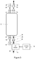
- FIG 2 is a schematic diagram of a handheld device 4 according to an embodiment of the invention.
- the handheld device 4 is sufficiently small and lightweight to make it readily portable for a subject 8 while still providing a useful number of breaths with supplemental oxygen, and the components of the handheld device 4 are designed and/or selected accordingly.
- the handheld device 4 comprises a subject interface 10 as described above, a housing 11, a container or tank 12 that stores and generates the oxygen to be dispensed to the subject 8 when the subject 8 inhales through the subject interface 10, an air blower, air pump or fan 14 that is arranged to supply air into the container 12 and a control unit 16 that controls the operation of the handheld device 4, including the operation of the air blower 14.
- the housing 11 may be shaped, contoured and/or textured to enable it to be easily held by the subject 8.
- the container 12 contains a material 15 for removing one or more specific gases from the air or other gas present in or passing through the container 12.
- the material 15 is provided to remove the one or more specific gases from the gas in the container 12 in order to increase the concentration of oxygen above that found in normal air (e.g. around 21% at sea level).
- the material 15 removes nitrogen from the gas in the container 12.
- the material 15 is an adsorbent material that adsorbs a specific gas or gases (e.g. nitrogen) from the air or other gas present in the container 12.
- the adsorbent material 15 is preferably a zeolite, such as a Li-doped Low-Silica zeolite X (LiLSX) zeolite.
- the material 15 can be an absorbent material that absorbs a specific gas or gases (e.g. nitrogen) from the air or other gas present in the container 12.
- a specific gas or gases e.g. nitrogen
- Such an absorbent material can comprise a metal organic framework (MOF).
- the container 12 has a generally cylindrical shape and a length of around 0.11 meters and a diameter of around 0.04 meters. It will be appreciated however, that containers 12 of other sizes and/or shapes can be used according to the desired size and/or shape of the handheld device 4.
- the container 12 contains about 0.094 kg of LiLSX pellets (e.g. pellets of 0.00055 meters diameter), although it will be appreciated that other quantities of zeolites, other zeolites and/or other adsorbent materials 15 can be used.
- the air blower, air pump or fan 14 is any type of device suitable for supplying air into the container 12 and provide a small increase in air pressure (overpressure) in the container 12.
- the terms air blower, air pump and fan are used interchangeably herein and a reference to one includes the others, and vice versa, unless otherwise expressly provided.
- the air blower 14 is able to provide a small overpressure in the region of, for example 0.01-0.15 bar (approximately 100-1500 mmH 2 O).
- the maximum air flow rate of the air blower 14 in operation is between 0.3 and 1 liter/minute.
- the air blower, air pump or fan it is sufficient for the air blower, air pump or fan to provide an increase in pressure in the container 12 of the order of up to 10%, or up to 20% in the pressure (an air pressure rise of up to 1136 mmH 2 O or up to 2066 mmH 2 O respectively), although air blowers, air pumps or fans 14 that provide higher pressure rises are also contemplated.
- the air blower 14 is preferably a small, low-power component that is suitable for use in a handheld device 4. It will also be appreciated that the air blower 14 is much smaller and less powerful than an air compressor that is often found in oxygen concentrators operating according to the pressure swing adsorption cycle.
- the control unit 16 can comprise one or more processors, processing units, processing modules and/or other electronic circuitry that is configured or programmed to control the operation of the handheld device 4 as described in more detail below.
- a first outlet 18 of the container 12 is connected to the subject interface 10 via a first valve 20, also referred to as the delivery valve herein, and a first conduit 22.
- the first valve 20 is used to release gas with an elevated oxygen level from the container 12 into the first conduit 22 and to the subject interface 10 when the subject 8 inhales.
- the opening and closing of the first valve 20 is controlled by control unit 16.
- the control unit 16 controls the opening and closing of the first valve 20 in response to detecting the subject 8 is inhaling or exhaling respectively.
- the opening and closing of the first valve 20 is directly in response to the subject 8 inhaling and exhaling through the subject interface 10 respectively (e.g.
- the first valve 20 can be configured such that a reduction in pressure in the first conduit 22 as the patient inhales is sufficient to open the first valve 20 and either the increase in pressure in the first conduit 22 as the patient exhales is sufficient to close the first valve 20 or the first valve 20 is loaded so that it automatically closes when the patient stops inhaling).
- the first valve 20 is a pulse dosing valve which only allows a preset volume of gas through (i.e. from the container 12) each time that the valve 20 is opened. The preset volume of gas that the first valve 20 is configured to dispense during each operation can depend on the needs of the subject 8.
- a typical volume is in the range of 15ml to 100ml, and in this case as normal tidal breathing volumes are of the order of 400ml to 500ml, the subject interface 10 and/or first conduit 22 can facilitate the mixing of the oxygen enriched gas dispensed through the first valve 20 with air drawn from the atmosphere to meet the required tidal volume.
- the construction and operation of the pulse dosing valve 20 is known to those skilled in the art, and further details are not provided herein.
- the air blower 14 is connected to a first inlet 24 of the container 12 via a second valve 26 and a second conduit 28.
- the air blower 14 also has an air inlet 30 through which the air blower 14 can draw air into the device 4.
- the second valve 26 is also referred to as a check valve herein.
- the second valve 26 is provided to prevent gas from flowing out of the container 12 and through the air blower 14 (particularly when the air blower 14 is not active).
- the second valve 26 is a check valve, otherwise known as a one-way valve or non-return valve.
- the second valve 26 preferably operates in response to the relative pressure between the container 12 and environment, i.e.
- valve 26 is closed when the gas pressure in the container 12 is higher than the air pressure external to the device 4, and the valve 26 is open when the external pressure (which can include the small overpressure caused by the operation of the air blower 14) exceeds the gas pressure in the container 12.
- a check valve 26 that operates according to the relative pressures is the preferred form for valve 26, it will be appreciated that other types of valve could be used, and it will also be appreciated that the opening and closing of the second valve 26 can be controlled by the control unit 16 (in which case the control unit 16 monitors the pressure inside the container 12 to determine when to open and close the second valve 26.
- the first inlet 24 and first outlet 18 are arranged on the container 12 so as to cause air blown into the container 12 by the air blower 14 to push out the gas stored in the container 12.
- the first inlet 24 is on a side of the container 12 that is different to the side of the container 12 having the first outlet 18.
- the first inlet 24 and first outlet 18 are on opposite sides of the container 12.
- the container 12 is provided with a second inlet 31 for receiving a 'purge' gas and a second outlet 32 for exhausting waste gas (i.e. the gas adsorbed by the adsorbent material 15).
- the second inlet 31 and second outlet 32 are arranged on the container 12 so as to cause oxygen-enriched air that passes into the container 12 through the second inlet 31 to push out the gas adsorbed in the adsorbent material 15.
- the second inlet 31 is on a side of the container 12 that is different to the side of the container 12 having the second outlet 32.
- the second inlet 31 and second outlet 32 are on opposite sides of the container 12 (although not necessarily on the same sides respectively as first outlet 18 and first inlet 24 as shown in Figure 2 ).
- the second inlet 31 is connected to a third conduit 34 via a third valve 36 which leads to a supply port 38 on the outside of the handheld device 4.
- the third valve 36 is also referred to herein as the load valve.
- the supply port 38 is configured to allow a source of oxygen, oxygen-enriched air, or other purging gas to be coupled to the handheld device 4 and thus supplied to the container 12 when the load valve 36 is open.
- the supply port 38 will be configured to connect to a corresponding port or outlet on the base unit 6 to receive the oxygen, oxygen-enriched air, or other purging gas.
- the operation of the third valve 36 is preferably controlled by the control unit 16.
- the second outlet 32 is connected to a fourth conduit 40 via a fourth valve 42 which leads to an exhaust port 44 on the outside of the handheld device 4.
- the fourth valve 42 is also referred to herein as the exhaust valve.
- the exhaust valve 42 is opened to allow waste gas (e.g. the gas that was adsorbed by adsorbent material 15 during previous operation of the handheld device 4) to flow out of the device 4 and into the atmosphere.
- waste gas e.g. the gas that was adsorbed by adsorbent material 15 during previous operation of the handheld device
- the operation of the fourth valve 42 is preferably controlled by the control unit 16.
- any of the first valve 20, second valve 26, third valve 36 and fourth valve 42 can comprise any of the following types of valve: a plug valve, a ball valve, a check valve, a butterfly valve, a solenoid, a pressure switch, and/or other pressure regulating device.
- a handheld device 4 may comprise a power source for powering the components described above and/or a user interface for allowing the subject to control the device 4.
- the power source may comprise, for example, one or more replaceable or rechargeable batteries that are capable of powering the handheld device 4 for at least several minutes.
- the user interface comprises components for enabling the subject 8 to receive information from the device 4 and/or interact with or control the device 4, and may include, for example, one or more buttons, switches or controls for activating, deactivating and otherwise controlling the operation of the device 4, one or more displays, lights, indicators, etc. for providing a visual output to the subject 8 and/or one or more speakers for providing an audible output to the subject 8.
- Figures 3 , 4 and 5 illustrate the operation of the handheld device 4 of Figure 2 when oxygen-enriched air is to be delivered to the subject 8 according to an aspect of the invention.
- Figure 3 shows the handheld device 4 of Figure 2 with the direction of the gas flows shown
- Figure 4 is a graph illustrating the operation of the valves 20, 26, 36 and 42 (although it will be appreciated that the specific timing of the opening and closing of the valves shown by the x-axis of the graph is merely exemplary and not limiting)
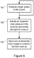
- Figure 5 is a flow chart illustrating the method of operating the handheld device 4.
- the container 12 in the handheld device 4 is fully 'charged' with oxygen-enriched air (i.e. air with oxygen content greater than 21%) to a pressure that is higher than the air pressure around the handheld device (i.e. higher than atmospheric pressure). All valves 20, 26, 36 and 42 are closed and the air blower 14 is deactivated.
- oxygen-enriched air i.e. air with oxygen content greater than 21%
- the container 12 is charged with gas that has an oxygen content of at least 40%, more preferably the container 12 is charged with gas that has an oxygen content of at least 60%, even more preferably the container 12 is charged with gas that has an oxygen content of at least 80%, and even more preferably the container 12 is charged with gas that has an oxygen content of at least 90%, for example 92%.
- the gas in the container 12 is at a pressure of at least 1.2 atmospheres, more preferably the gas in the container 12 is at a pressure of at least 1.5 atmospheres, and even more preferably the gas in the container 12 is at a pressure of at least 1.8 atmospheres.
- Activation of the handheld device 4 results in the delivery valve 20 being opened which allows a flow or pulse of oxygen-enriched air from the container 12 through the first conduit 22 and to the subject 8 (step 101 of Figure 5 ).
- the delivery valve 20 is open throughout the delivery operation (e.g. from 0 seconds to 66 seconds), in practice the delivery valve 20 is opened and closed in line with the subject's breathing during the delivery operation. The other valves 26, 36 and 42 remain closed.
- the control unit 16 controls the air blower 14 to start operating shortly after the delivery valve 20 is first opened (this can be any time in the first 20 seconds in this example). This corresponds to step 103 in Figure 5 .
- the control unit 16 can activate the air blower 14 when the monitored pressure is close to or at atmospheric pressure.
- the air blower 14 When the pressure in the container 12 matches atmospheric pressure and the check valve 26 opens, the air blower 14 will be pushing air (drawn from the outside of the handheld device 4) into the container 12 and through the adsorbent material 15.
- the adsorbent material 15 adsorbs specific gas or gases (e.g. nitrogen) from the air in order to increase the concentration of oxygen in the air supplied to the subject 8.
- the operation of the air blower 14 causes a small overpressure in the container (e.g. around 0.01-0.15 bar) which increases the rate at which air passes through the container 12 and to the subject 8 and also slightly increases the ability of the adsorbent material 15 to adsorb the specific gas or gases.
- the operation of the air blower 14 also acts to push the oxygen-enriched air initially stored in the container 12 out to the subject 8.
- the adsorbent material 15 gradually becomes saturated with the specific gas it is adsorbing (e.g. nitrogen).
- yN2(z) 1-yN2(z).
- MTZ Mass Transfer Zone
- the air output to the subject 8 will have the same oxygen content as the air blown into the container 12 by the air blower 14.
- the container 12 of the handheld device 4 requires recharging before it can be used again to provide supplemental oxygen to the subject 8.
- the control unit 16 therefore deactivates the air blower 14 (step 105).
- the control unit 16 may also close or prevent further opening of the delivery valve 20 and/or close the check valve 26 (if it is controlled by the control unit 16).
- the control unit 16 can deactivate the blower 14 and close, or prevent further opening of, the delivery valve 20 (and optionally also the check valve 26 if it is under the control of the control unit 16) after the handheld device 4 has been used for a certain amount of time since the last full recharge of the device 4 or after a certain amount of time from the first inhalation (where the certain amount of time is set around the amount of time that the device 4 is expected to be able to provide supplemental oxygen), or after a certain number of inhalations by the subject 8 (where the certain number of inhalations is the total number of inhalations that the device 4 is expected to be able to provide supplemental oxygen).
- control unit 16 can deactivate the blower 14 and close, or prevent further opening of, the delivery valve 20 (and check valve 26 as above) in response to detecting that the oxygen content of the container 12 or the gas output to the subject 8 is below or at a predetermined level (e.g. 21%), in which case an appropriate sensor can be provided to monitor the oxygen content of the product gas.
- control unit 16 can deactivate the blower 14 and close, or prevent further opening of, the delivery valve 20 (and check valve 26 as above) in response to detecting an increase in the temperature of the gas flow to the subject 8.
- a temperature increase will occur when there is a 'breakthrough' of the air blown into the container 12 into the air flow to the subject 8, and this temperature increase will occur over a short period of time, for example of the order of 0.1 to 1 seconds. In the exemplary embodiment described herein, the temperature increase is of the order of 9K.
- a temperature sensor can be coupled to the control unit 16 and provided in or at the first outlet 18 or in the first conduit 22 to measure this temperature change.
- Figures 7 , 8 and 9 illustrate the operation of the handheld device 4 of Figure 2 when the container 12 is to be recharged to enable oxygen-enriched air to again be delivered to the subject 8 according to an aspect of the invention.
- Figure 7 shows the handheld device 4 of Figure 2 with the direction of the gas flows shown
- Figure 8 is a graph illustrating the operation of the valves 20, 26, 36 and 42 (although it will be appreciated that the specific timing of the opening and closing of the valves shown by the x-axis of the graph is merely exemplary and not limiting)
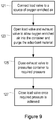
- Figure 9 is a flow chart illustrating the method of operating the handheld device 4.
- the container 12 in the handheld device 4 will contain air with an oxygen content of around 21% (i.e. the same as the air around the handheld device 4) and the adsorbent material 15 will be saturated with the adsorbed gas (e.g. nitrogen).
- the recharging process purges the adsorbed gas from the adsorbent material 15 and the container 12.
- the recharging process also fills the container 12 with oxygen-enriched gas to a pressure that is preferably higher than atmospheric pressure. The process starts with all valves 20, 26, 36 and 42 being closed and the air blower 14 deactivated.
- the handheld device 4 is connected to a source of oxygen or oxygen-enriched air, for example liquid oxygen or compressed gas or air with elevated oxygen levels, or an oxygen concentrator that operates according to the known pressure swing adsorption cycle principle and that supplies gas with elevated levels of oxygen (i.e. elevated above the normal oxygen content of air at sea level of around 21%).
- a source of oxygen or oxygen-enriched air for example liquid oxygen or compressed gas or air with elevated oxygen levels, or an oxygen concentrator that operates according to the known pressure swing adsorption cycle principle and that supplies gas with elevated levels of oxygen (i.e. elevated above the normal oxygen content of air at sea level of around 21%).
- the source of oxygen or oxygen-enriched gas can be provided via a base unit 6 or directly to the handheld device 4.
- the oxygen-enriched gas has an oxygen content of at least 40%, more preferably an oxygen content of at least 60%, even more preferably an oxygen content of at least 80%, and even more preferably an oxygen content of at least 90%, for example 92%.
- the delivery valve 20 and check valve 26 remain closed.
- the load valve 36 and exhaust valve 42 are opened (step 123) by the control unit 16 (or optionally by a control unit in the base unit 6) at the start of the process to enable oxygen-enriched gas to flow into the container 12 and exhaust gases to flow out of the container 12 through the exhaust valve 42 and into the atmosphere.
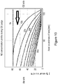
- FIG. 10 illustrates an exemplary nitrogen concentration profile during the recharging of the handheld device 4, which is based on a simulation of the device 4.
- Figure 10 illustrates that high values of yN2 move faster than low values of yN2. Therefore, the high N2 concentration values will leave the container 12 quite early in the process, but the low N2 concentration values need much more time (and oxygen purge gas volume) to do so. This means that it is impossible to purge "all" of the nitrogen out of the adsorbent material 15.
- the actual "purge time” setting will be a compromise between the time required to reach the container's storage capacity and the oxygen purge volume required.
- the flow of oxygen-enriched gas continues regardless of the concentration of the gas to be adsorbed in the container 12. This is in contrast to an oxygen concentrator, where purging is stopped when the concentration of the gas to be adsorbed goes below a threshold amount (e.g. below 78%) since it is important not to waste oxygen and thus ensure efficient oxygen concentration operation.
- a threshold amount e.g. below 78% since it is important not to waste oxygen and thus ensure efficient oxygen concentration operation.
- the purge duration is limited (typically to less than 20 seconds) to ensure this efficient operation (although this 'efficient' operation means that the adsorbent material is not fully purged of nitrogen).
- purging is performed in order to get the adsorbent material 15 in the container 12 is as clean as possible, and it does not matter that some oxygen provided in the purging or recharging phase is wasted (i.e. not stored in the container 12).
- the purging step can last around 100 seconds.
- the exhaust valve 42 is closed (as shown in Figure 8 and step 125 of Figure 9 ) and the flow of oxygen-enriched gas into the container 12 continues in order to pressurize the container 12 to the required initial pressure (e.g. 1.8 atmospheres in some embodiments).
- the required initial pressure e.g. 1.8 atmospheres in some embodiments.
- step 127 the load valve 36 is closed and the recharging process is completed (step 127).
- the device 4 is now ready for use by the subject 8.
- the container 12 has a generally cylindrical shape, a length of around 0.11 meters, a diameter of around 0.04 meters and contains about 0.094 kg of LiLSX pellets.
- the handheld device 4 With the container 12 being charged with air enriched to 92% oxygen and to a pressure of 1.8 atmospheres, the handheld device 4 is able to deliver 21 pulses of oxygen-enriched air with a pulse volume for the subject 8 of 46 ml, which means that the handheld device 4 can be used continuously for around 65 seconds before requiring a recharge.
- a handheld device 4 having a container charged to the same oxygen concentration and pressure but that does not include an adsorbent material 15 or an air blower 14 would provide just two 46 ml pulses of oxygen-enriched air, and allow the device to be used continuously for only around 6 seconds before requiring recharging.
- a container 12 with an adsorbent material 15 and a fan 14 to blow additional air through the container 12 during use provides particularly strong performance compared to a standard container or canister of oxygen.
- This performance is caused in part by the oxygen contained in the air flow from the fan 14 being almost entirely added to the 92% (or other concentration) oxygen stream output to the subject 8 when the subject 8 inhales, and also by the adsorbent material 15 (e.g. zeolite sieve bed) being cooled by around 13 Kelvin (in the above example) due to desorption of the specific gas (e.g. nitrogen) during the oxygen purging/recharging process.
- This cooling increases the capacity of the adsorbent material to adsorb the specific gas by around 20%.
- the first scenario corresponds to a container 12 with no adsorbent material 15 or fan 14, the second to a container 12 with a fan 14 but no adsorbent material, the third to a container 12 with adsorbent material 15 but no fan 14 and the fourth to a container 12 as shown in Figure 2 with an adsorbent material 15 and a fan 14.
- 101 ml of oxygen is output from the container 12 as it is depressurized from 1.8 atmospheres to 1 atmosphere.
- the oxygen remaining in the container 12 after depressurization to 1 atmosphere is expelled by the air blown into the container 12 by the fan 14, which gives a total output of 227 ml.
- the third scenario there is never any air inside the container 12, only oxygen at 92% purity and at different pressures, which means that the temperature of the adsorbent material 15 (zeolite) hardly varies (only about by 2.4K).
- the presence of the adsorbent material 15 increases the oxygen capacity of the container 12 by a factor of about 2.85, which means that the amount of oxygen in the tank at 1.8 atmospheres is 647 ml (plus 196ml of nitrogen).
- the handheld device 4 is recharged by coupling the device 4 to a source of oxygen-enriched gas or to a base unit 6 that has a source of oxygen-enriched gas.
- This embodiment can therefore allow a discharged container 12 to be swapped out for a previously-recharged container 12 and allow the device 4 to continue to be used straight away.
- the container 12 will be configured so that when it is removed from the device 4 the inlets 18, 31 and outlets 24, 32 are closed to prevent air entering or leaving the container 12 (which is particularly important when the container 12 has been recharged). This may be achieved by configuring the valves 20, 26, 32 and 36 so that they are part of the removable container 12, or by providing additional valves on the container 12.
- Figure 11 illustrates a handheld device 50 according to another or further aspect of the invention.
- the handheld device 50 is configured to provide supplemental oxygen to the subject 8 when they inhale, and to provide increased pressure or resistance to the subject 8 when they exhale.
- This handheld device 50 can be as described and shown in any of the above embodiments, and further comprise some means for applying a positive air pressure to the subject 8 when the subject 8 exhales through the subject interface (e.g. subject interface 52 in Figure 11 ).
- the handheld device 50 can comprise a simple oxygen canister that does not include an adsorbent material or fan as described above, and the device 50 includes some means for applying a positive air pressure to the subject 8 when the subject 8 exhales through subject interface 52.
- the illustrated handheld device 50 comprises a subject interface 52 through which the subject inhales and exhales, a first conduit 54 that couples the subject interface 52 to a container 56 that holds oxygen-enriched air (which can be as shown in Figure 2 above and further comprise an adsorbent material and/or a fan or air blower), a one-way valve or check valve 58 that prevents exhaled breath from entering the container 56 and a second conduit 60 that couples the subject interface 52 to an outlet (exhalation port) 62 through which exhaled breath passes.
- the second conduit 60 includes some means 64 for applying a positive air pressure to the subject when the subject exhales.
- the means 64 is a partial obstruction or restriction in the second conduit 60 through which the subject exhales (e.g.
- the means 64 can be implemented as a passive flow restriction in an exhalation port 62.
- the means 64 actively provides positive pressure to the subject as they exhale.
- the handheld device 4 or another part of the system 2 may comprise a sensor for measuring the oxygen levels in the subject 8.
- a sensor can be a sensor that measures the peripheral capillary oxygen saturation (SpO2).
- the handheld device 4 or system 2 can be part of a larger 'ecosystem' of devices, such as any one or more of a smart phone interface/application, smart sensors and various subject interfaces.
- one sensor that can be used with the handheld device 4 is an SpO2 sensor for measuring peripheral oxygenation levels, for example at the fingertip or at the ear.
- the SpO2 sensor and/or other type of sensor is incorporated into a wrist watch or similar device to allow SpO2 to be measured during activity and/or exercise in order to identify possible exercise-induced desaturation events (e.g. oxygen levels below 90%).
- the smart phone can be used to provide feedback or instructions to the subject 8 to supplement their oxygen levels in the event that the level is below the threshold.
- a computer program may be stored/distributed on a suitable medium, such as an optical storage medium or a solid-state medium supplied together with or as part of other hardware, but may also be distributed in other forms, such as via the Internet or other wired or wireless telecommunication systems. Any reference signs in the claims should not be construed as limiting the scope.
Claims (10)
- Dispositif portatif (4) pour fournir de l'oxygène d'appoint à un sujet (8), le dispositif portatif étant conçu pour être aisément maintenu par le sujet et aisément portable pour le sujet, le dispositif (4) comprenant :un boîtier (11) ;une interface sujet (10) à travers laquelle le sujet (8) peut inhaler ;un récipient (12) qui a :une première sortie (18) raccordée à l'interface sujet pour permettre l'inhalation par le sujet (8) de gaz avec un niveau d'oxygène élevé stocké dans le récipient (12),une première entrée (24) pour recevoir de l'air,une seconde entrée (31) pour recevoir un gaz de purge ;une seconde sortie (32) pour évacuer du gaz résiduaire ; etun matériau (15) pour éliminer un gaz spécifique de l'air passant à travers le récipient (12) afin d'augmenter la teneur en oxygène de l'air passant à travers le récipient (12) ;une soufflerie d'air (14) qui est raccordée à la première entrée (24) du récipient (12) et qui est configurée pour fournir de l'air dans le récipient (12) lorsque le sujet (8) utilise le dispositif (4) ; etune première soupape (20) située entre le récipient (12) et l'interface sujet (10) pour permettre un écoulement d'oxygène d'appoint vers le sujet (8),dans lequel la sortie de fluide (18) est raccordée à l'interface sujet via la première soupape (20) et un premier conduit (22),dans lequel le boîtier a une entrée d'air (30) à travers laquelle la soufflerie d'air (14) peut aspirer de l'air dans le dispositif etdans lequel le boîtier a un orifice d'alimentation (38) pour recevoir le gaz de purge,dans lequel le boîtier a un orifice d'échappement (44) pour évacuer le gaz résiduaire.
- Dispositif (4) selon la revendication 1, dans lequel ledit dispositif comprend en outre une unité de commande (16) pour commander le fonctionnement du dispositif (4).
- Dispositif (4) selon la revendication 2, dans lequel le récipient (12) est configuré pour stocker du gaz avec un niveau d'oxygène élevé à une pression supérieure à la pression atmosphérique.
- Dispositif (4) selon la revendication 3, dans lequel la soufflerie d'air (14) est configurée pour être activée par l'unité de commande (16) afin de fournir de l'air dans le récipient (12) lorsque la pression du gaz avec une teneur en oxygène élevée stocké dans le récipient (12) se trouve à la pression atmosphérique ou près de celle-ci.
- Dispositif (4) selon la revendication 4, dans lequel la soufflerie d'air (14) est configurée pour être désactivée par l'unité de commande (16) lorsque l'une quelconque des conditions suivantes est satisfaite :(i) lorsque le matériau (15) est saturé du gaz spécifique ;(ii) après une période prédéterminée depuis une première inhalation par le sujet (8) ;(iii) après que le sujet (8) a utilisé le dispositif (4) pendant une période prédéterminée depuis la dernière recharge du dispositif (4) ;(iv) après un nombre prédéterminé d'inhalations par le sujet (8) ;(v) lorsqu'il y a une augmentation de la température du gaz fourni au sujet (8) ; ou(vi) lorsque la teneur en oxygène du gaz fourni au sujet (8) se situe en dessous d'un seuil.
- Dispositif (4) selon l'une quelconque des revendications précédentes, dans lequel la première entrée (24) et la première sortie (18) sont agencées l'une par rapport à l'autre de sorte que l'air soufflé dans le récipient (12) à travers la première entrée (24) par la soufflerie d'air (14) éjecte le gaz avec un niveau d'oxygène élevé stocké dans le récipient (12) à travers la première sortie (18).
- Dispositif (4) selon l'une quelconque des revendications précédentes, le dispositif (4) comprenant en outre une soupape de retenue (26) positionnée entre la soufflerie d'air (14) et la première entrée (24), la soupape de retenue (26) étant configurée pour se fermer lorsque la pression du gaz d'un niveau d'oxygène élevé stocké dans le récipient (12) se situe au-dessus de la pression atmosphérique afin d'empêcher le gaz du récipient (12) de s'écouler à travers la soufflerie d'air (14) lorsque la soufflerie d'air (14) est désactivée et étant configuré pour s'ouvrir lorsque la pression du gaz d'un niveau d'oxygène élevé stocké dans le récipient (12) se situe à la pression atmosphérique ou en dessous de celle-ci afin de permettre l'alimentation en air dans le récipient (12) par la soufflerie d'air (14) ;
la seconde entrée (31) est configurée pour recevoir du gaz d'un niveau d'oxygène élevé au cours d'un processus de recharge et la seconde sortie (32) est configurée pour décharger du gaz résiduaire au cours du procédé de recharge, le dispositif (4) comprenant en outre une soupape de charge (36) raccordée à la seconde entrée (31) qui est configurée pour être ouverte au début du processus de recharge afin de permettre de fournir du gaz d'un niveau d'oxygène élevé dans le récipient (12) afin de purger le matériau du gaz spécifique, et une soupape d'échappement (42) raccordée à la seconde sortie (32) qui est configurée pour être ouverte au départ du processus de recharge afin de permettre au gaz résiduaire de sortir du récipient (12). - Dispositif (4) selon la revendication 7, dans lequel la soupape d'échappement (42) est configurée pour être fermée au cours du processus de recharge tandis que le gaz d'un niveau d'oxygène élevé est fourni au récipient (12) à travers la soupape de charge (36) et la seconde entrée (31) afin de stocker du gaz d'un niveau d'oxygène élevé dans le récipient (12).
- Dispositif (4) selon l'une quelconque des revendications précédentes, le dispositif (4) comprenant en outre :
des moyens (64) pour appliquer une pression d'air positive au sujet (8) lorsque le sujet (8) exhale à travers l'interface sujet (10). - Système d'oxygène d'appoint (2) comprenant :un dispositif portable (4) selon l'une quelconque des revendications 1 à 9 ; etune source (6) de gaz d'un niveau d'oxygène élevé qui peut être sélectivement couplée au dispositif (4) afin de recharger le dispositif en gaz d'un niveau d'oxygène élevé et/ou de purger le matériau du gaz spécifique.
Applications Claiming Priority (2)
| Application Number | Priority Date | Filing Date | Title |
|---|---|---|---|
| EP14185468.7A EP2997991A1 (fr) | 2014-09-19 | 2014-09-19 | Dispositif pour fournir de l'oxygène d'appoint à un sujet |
| PCT/EP2015/068899 WO2016041718A1 (fr) | 2014-09-19 | 2015-08-18 | Dispositif de fourniture d'oxygène supplémentaire à un sujet |
Publications (2)
| Publication Number | Publication Date |
|---|---|
| EP3193996A1 EP3193996A1 (fr) | 2017-07-26 |
| EP3193996B1 true EP3193996B1 (fr) | 2019-03-06 |
Family
ID=51582286
Family Applications (2)
| Application Number | Title | Priority Date | Filing Date |
|---|---|---|---|
| EP14185468.7A Ceased EP2997991A1 (fr) | 2014-09-19 | 2014-09-19 | Dispositif pour fournir de l'oxygène d'appoint à un sujet |
| EP15750757.5A Not-in-force EP3193996B1 (fr) | 2014-09-19 | 2015-08-18 | Dispositif pour fournir de l'oxygène d'appoint à un sujet |
Family Applications Before (1)
| Application Number | Title | Priority Date | Filing Date |
|---|---|---|---|
| EP14185468.7A Ceased EP2997991A1 (fr) | 2014-09-19 | 2014-09-19 | Dispositif pour fournir de l'oxygène d'appoint à un sujet |
Country Status (6)
| Country | Link |
|---|---|
| US (1) | US20170281897A1 (fr) |
| EP (2) | EP2997991A1 (fr) |
| JP (1) | JP2017528228A (fr) |
| CN (1) | CN106714936A (fr) |
| RU (1) | RU2017113434A (fr) |
| WO (1) | WO2016041718A1 (fr) |
Families Citing this family (2)
| Publication number | Priority date | Publication date | Assignee | Title |
|---|---|---|---|---|
| JP6808020B2 (ja) * | 2017-03-31 | 2021-01-06 | 帝人ファーマ株式会社 | 呼吸情報取得装置および呼吸情報取得方法 |
| US20210220599A1 (en) | 2020-01-21 | 2021-07-22 | Wearair Ventures, Inc. | Efficient enriched oxygen airflow systems and methods |
Citations (4)
| Publication number | Priority date | Publication date | Assignee | Title |
|---|---|---|---|---|
| EP1568391A1 (fr) * | 2004-01-22 | 2005-08-31 | Air Products And Chemicals, Inc. | Concentrateur d'oxygene à deux modes |
| EP1967224A2 (fr) * | 2007-02-27 | 2008-09-10 | Delphi Technologies, Inc. | Système de concentrateur d'oxygène |
| US20130216627A1 (en) * | 2011-08-26 | 2013-08-22 | Stephen Douglas Galbraith | Portable Oxygen Enrichment Device and Method of Use |
| WO2013126285A1 (fr) * | 2012-02-21 | 2013-08-29 | Oxus America, Inc. | Système concentrateur d'oxygène |
Family Cites Families (20)
| Publication number | Priority date | Publication date | Assignee | Title |
|---|---|---|---|---|
| US4561865A (en) * | 1983-11-01 | 1985-12-31 | Greene & Kellogg, Inc. | Single bed pressure swing adsorption gas separation system |
| US6126721A (en) * | 1998-08-28 | 2000-10-03 | Compact Membrane Systems, Inc. | Oxygen enriched air supply apparatus |
| US6217635B1 (en) * | 1998-11-09 | 2001-04-17 | Fantom Technologies Inc. | Method and apparatus for concentrating a gas using a single stage adsorption chamber |
| US6346139B1 (en) * | 1999-05-12 | 2002-02-12 | Respironics, Inc. | Total delivery oxygen concentration system |
| US6557549B2 (en) * | 2000-04-11 | 2003-05-06 | Trudell Medical International | Aerosol delivery apparatus with positive expiratory pressure capacity |
| FR2809329B1 (fr) * | 2000-05-25 | 2002-08-16 | Air Liquide | Concentrateur d'oxygene portable |
| CN1221303C (zh) * | 2000-08-02 | 2005-10-05 | 配戴式氧气用品有限公司 | 可佩带的小型氧浓缩器 |
| US7736132B2 (en) * | 2006-04-03 | 2010-06-15 | Respironics Oxytec, Inc. | Compressors and methods for use |
| CN101932831B (zh) * | 2006-04-03 | 2014-06-18 | 伟康公司 | 便携式氧浓缩设备 |
| US8753435B2 (en) * | 2006-04-03 | 2014-06-17 | Ric Investments, Llc | Portable oxygen concentrator |
| JP5074160B2 (ja) * | 2007-11-22 | 2012-11-14 | テルモ株式会社 | 酸素濃縮装置 |
| WO2009105627A1 (fr) * | 2008-02-22 | 2009-08-27 | Delphi Technologies, Inc. | Concentrateur d'oxygène à régulation de température |
| US20090214393A1 (en) * | 2008-02-22 | 2009-08-27 | Chekal Michael P | Method of generating an oxygen-enriched gas for a user |
| US8226745B2 (en) * | 2009-04-28 | 2012-07-24 | Lehigh University | Miniature oxygen concentrators and methods |
| US20120055483A1 (en) * | 2010-09-07 | 2012-03-08 | Wilkinson William R | Shutdown system and method for an oxygen concentrator |
| US10307562B2 (en) * | 2012-04-13 | 2019-06-04 | Fresca Medical, Inc. | Auto-feedback valve for a sleep apnea device |
| US20150136129A1 (en) * | 2012-05-30 | 2015-05-21 | Koninklijke Philips N.V. | Portable handheld blending gas enriched pressure support system and method |
| NZ707159A (en) * | 2012-10-12 | 2018-06-29 | Inova Labs Inc | Dual oxygen concentrator systems and methods |
| EP4249104A3 (fr) * | 2012-10-12 | 2023-10-04 | Inova Labs, Inc. | Systèmes et procédés de concentrateur d'oxygène |
| FR3000137B1 (fr) * | 2012-12-20 | 2018-11-23 | Safran Helicopter Engines | Dispositif et procede d'augmentation temporaire de puissance |
-
2014
- 2014-09-19 EP EP14185468.7A patent/EP2997991A1/fr not_active Ceased
-
2015
- 2015-08-18 RU RU2017113434A patent/RU2017113434A/ru not_active Application Discontinuation
- 2015-08-18 WO PCT/EP2015/068899 patent/WO2016041718A1/fr active Application Filing
- 2015-08-18 US US15/512,656 patent/US20170281897A1/en not_active Abandoned
- 2015-08-18 CN CN201580050207.2A patent/CN106714936A/zh active Pending
- 2015-08-18 JP JP2017513521A patent/JP2017528228A/ja active Pending
- 2015-08-18 EP EP15750757.5A patent/EP3193996B1/fr not_active Not-in-force
Patent Citations (4)
| Publication number | Priority date | Publication date | Assignee | Title |
|---|---|---|---|---|
| EP1568391A1 (fr) * | 2004-01-22 | 2005-08-31 | Air Products And Chemicals, Inc. | Concentrateur d'oxygene à deux modes |
| EP1967224A2 (fr) * | 2007-02-27 | 2008-09-10 | Delphi Technologies, Inc. | Système de concentrateur d'oxygène |
| US20130216627A1 (en) * | 2011-08-26 | 2013-08-22 | Stephen Douglas Galbraith | Portable Oxygen Enrichment Device and Method of Use |
| WO2013126285A1 (fr) * | 2012-02-21 | 2013-08-29 | Oxus America, Inc. | Système concentrateur d'oxygène |
Also Published As
| Publication number | Publication date |
|---|---|
| US20170281897A1 (en) | 2017-10-05 |
| RU2017113434A (ru) | 2018-10-19 |
| EP3193996A1 (fr) | 2017-07-26 |
| EP2997991A1 (fr) | 2016-03-23 |
| JP2017528228A (ja) | 2017-09-28 |
| WO2016041718A1 (fr) | 2016-03-24 |
| CN106714936A (zh) | 2017-05-24 |
| RU2017113434A3 (fr) | 2019-02-27 |
Similar Documents
| Publication | Publication Date | Title |
|---|---|---|
| JP7086146B2 (ja) | 酸素濃縮器システムおよび方法 | |
| CN102245245B (zh) | 可变流量氧疗 | |
| US9993765B2 (en) | Portable oxygen enrichment device and method of use | |
| US8603228B2 (en) | Power management systems and methods for use in an oxygen concentrator | |
| JP6336991B2 (ja) | 酸素濃縮器二重化システムおよび方法 | |
| US20120055483A1 (en) | Shutdown system and method for an oxygen concentrator | |
| US20120055480A1 (en) | Ventilator systems and methods | |
| US20120055477A1 (en) | Oxygen concentrator apparatus configured for high altitude use | |
| JP2002085566A (ja) | 酸素濃縮器及び制御装置並びに記録媒体 | |
| US20120055478A1 (en) | Positive pressure therapy systems and methods | |
| JP2021520258A (ja) | 呼吸器疾患治療のための方法及び装置 | |
| WO2012167205A1 (fr) | Ventilateur à générateur d'oxygène intégré | |
| CN115916311A (zh) | 便携式氧气浓缩器中的功率管理 | |
| WO2017006186A1 (fr) | Appareil de réinspiration d'oxygène et son procédé d'utilisation | |
| WO2015109236A1 (fr) | Concentrateur d'oxygène pour distribution d'oxygène haute pression à boucle de circulation d'oxygène et portabilité améliorée | |
| EP3193996B1 (fr) | Dispositif pour fournir de l'oxygène d'appoint à un sujet | |
| JP7170743B2 (ja) | 一酸化窒素投与装置 | |
| US20220096780A1 (en) | Methods and apparatus for treating a respiratory disorder | |
| JP3531215B2 (ja) | 医療用酸素ガス供給装置 | |
| KR102626986B1 (ko) | 중계 투여 장치 및 일산화질소 투여 시스템 | |
| JP2015080699A (ja) | 高濃度酸素吸入システム | |
| JP2023521979A (ja) | 濃縮された治療ガスを呼吸障害のために提供する方法および装置 | |
| CN114929318A (zh) | 用于控制氧气浓缩器的方法和设备 | |
| JP2019162337A (ja) | 酸素濃縮装置およびその制御方法 | |
| KR102572397B1 (ko) | 일산화질소 투여 장치 |
Legal Events
| Date | Code | Title | Description |
|---|---|---|---|
| STAA | Information on the status of an ep patent application or granted ep patent |
Free format text: STATUS: THE INTERNATIONAL PUBLICATION HAS BEEN MADE |
|
| PUAI | Public reference made under article 153(3) epc to a published international application that has entered the european phase |
Free format text: ORIGINAL CODE: 0009012 |
|
| STAA | Information on the status of an ep patent application or granted ep patent |
Free format text: STATUS: REQUEST FOR EXAMINATION WAS MADE |
|
| 17P | Request for examination filed |
Effective date: 20170419 |
|
| AK | Designated contracting states |
Kind code of ref document: A1 Designated state(s): AL AT BE BG CH CY CZ DE DK EE ES FI FR GB GR HR HU IE IS IT LI LT LU LV MC MK MT NL NO PL PT RO RS SE SI SK SM TR |
|
| AX | Request for extension of the european patent |
Extension state: BA ME |
|
| STAA | Information on the status of an ep patent application or granted ep patent |
Free format text: STATUS: EXAMINATION IS IN PROGRESS |
|
| 17Q | First examination report despatched |
Effective date: 20171102 |
|
| DAV | Request for validation of the european patent (deleted) | ||
| DAX | Request for extension of the european patent (deleted) | ||
| GRAP | Despatch of communication of intention to grant a patent |
Free format text: ORIGINAL CODE: EPIDOSNIGR1 |
|
| STAA | Information on the status of an ep patent application or granted ep patent |
Free format text: STATUS: GRANT OF PATENT IS INTENDED |
|
| INTG | Intention to grant announced |
Effective date: 20180925 |
|
| GRAS | Grant fee paid |
Free format text: ORIGINAL CODE: EPIDOSNIGR3 |
|
| GRAA | (expected) grant |
Free format text: ORIGINAL CODE: 0009210 |
|
| STAA | Information on the status of an ep patent application or granted ep patent |
Free format text: STATUS: THE PATENT HAS BEEN GRANTED |
|
| AK | Designated contracting states |
Kind code of ref document: B1 Designated state(s): AL AT BE BG CH CY CZ DE DK EE ES FI FR GB GR HR HU IE IS IT LI LT LU LV MC MK MT NL NO PL PT RO RS SE SI SK SM TR |
|
| REG | Reference to a national code |
Ref country code: GB Ref legal event code: FG4D |
|
| REG | Reference to a national code |
Ref country code: CH Ref legal event code: EP Ref country code: AT Ref legal event code: REF Ref document number: 1103719 Country of ref document: AT Kind code of ref document: T Effective date: 20190315 |
|
| REG | Reference to a national code |
Ref country code: DE Ref legal event code: R096 Ref document number: 602015025896 Country of ref document: DE |
|
| REG | Reference to a national code |
Ref country code: IE Ref legal event code: FG4D |
|
| REG | Reference to a national code |
Ref country code: NL Ref legal event code: MP Effective date: 20190306 |
|
| REG | Reference to a national code |
Ref country code: LT Ref legal event code: MG4D |
|
| PG25 | Lapsed in a contracting state [announced via postgrant information from national office to epo] |
Ref country code: LT Free format text: LAPSE BECAUSE OF FAILURE TO SUBMIT A TRANSLATION OF THE DESCRIPTION OR TO PAY THE FEE WITHIN THE PRESCRIBED TIME-LIMIT Effective date: 20190306 Ref country code: FI Free format text: LAPSE BECAUSE OF FAILURE TO SUBMIT A TRANSLATION OF THE DESCRIPTION OR TO PAY THE FEE WITHIN THE PRESCRIBED TIME-LIMIT Effective date: 20190306 Ref country code: NO Free format text: LAPSE BECAUSE OF FAILURE TO SUBMIT A TRANSLATION OF THE DESCRIPTION OR TO PAY THE FEE WITHIN THE PRESCRIBED TIME-LIMIT Effective date: 20190606 Ref country code: SE Free format text: LAPSE BECAUSE OF FAILURE TO SUBMIT A TRANSLATION OF THE DESCRIPTION OR TO PAY THE FEE WITHIN THE PRESCRIBED TIME-LIMIT Effective date: 20190306 |
|
| PG25 | Lapsed in a contracting state [announced via postgrant information from national office to epo] |
Ref country code: RS Free format text: LAPSE BECAUSE OF FAILURE TO SUBMIT A TRANSLATION OF THE DESCRIPTION OR TO PAY THE FEE WITHIN THE PRESCRIBED TIME-LIMIT Effective date: 20190306 Ref country code: GR Free format text: LAPSE BECAUSE OF FAILURE TO SUBMIT A TRANSLATION OF THE DESCRIPTION OR TO PAY THE FEE WITHIN THE PRESCRIBED TIME-LIMIT Effective date: 20190607 Ref country code: HR Free format text: LAPSE BECAUSE OF FAILURE TO SUBMIT A TRANSLATION OF THE DESCRIPTION OR TO PAY THE FEE WITHIN THE PRESCRIBED TIME-LIMIT Effective date: 20190306 Ref country code: LV Free format text: LAPSE BECAUSE OF FAILURE TO SUBMIT A TRANSLATION OF THE DESCRIPTION OR TO PAY THE FEE WITHIN THE PRESCRIBED TIME-LIMIT Effective date: 20190306 Ref country code: BG Free format text: LAPSE BECAUSE OF FAILURE TO SUBMIT A TRANSLATION OF THE DESCRIPTION OR TO PAY THE FEE WITHIN THE PRESCRIBED TIME-LIMIT Effective date: 20190606 Ref country code: NL Free format text: LAPSE BECAUSE OF FAILURE TO SUBMIT A TRANSLATION OF THE DESCRIPTION OR TO PAY THE FEE WITHIN THE PRESCRIBED TIME-LIMIT Effective date: 20190306 |
|
| REG | Reference to a national code |
Ref country code: AT Ref legal event code: MK05 Ref document number: 1103719 Country of ref document: AT Kind code of ref document: T Effective date: 20190306 |
|
| PG25 | Lapsed in a contracting state [announced via postgrant information from national office to epo] |
Ref country code: SK Free format text: LAPSE BECAUSE OF FAILURE TO SUBMIT A TRANSLATION OF THE DESCRIPTION OR TO PAY THE FEE WITHIN THE PRESCRIBED TIME-LIMIT Effective date: 20190306 Ref country code: RO Free format text: LAPSE BECAUSE OF FAILURE TO SUBMIT A TRANSLATION OF THE DESCRIPTION OR TO PAY THE FEE WITHIN THE PRESCRIBED TIME-LIMIT Effective date: 20190306 Ref country code: CZ Free format text: LAPSE BECAUSE OF FAILURE TO SUBMIT A TRANSLATION OF THE DESCRIPTION OR TO PAY THE FEE WITHIN THE PRESCRIBED TIME-LIMIT Effective date: 20190306 Ref country code: PT Free format text: LAPSE BECAUSE OF FAILURE TO SUBMIT A TRANSLATION OF THE DESCRIPTION OR TO PAY THE FEE WITHIN THE PRESCRIBED TIME-LIMIT Effective date: 20190706 Ref country code: ES Free format text: LAPSE BECAUSE OF FAILURE TO SUBMIT A TRANSLATION OF THE DESCRIPTION OR TO PAY THE FEE WITHIN THE PRESCRIBED TIME-LIMIT Effective date: 20190306 Ref country code: AL Free format text: LAPSE BECAUSE OF FAILURE TO SUBMIT A TRANSLATION OF THE DESCRIPTION OR TO PAY THE FEE WITHIN THE PRESCRIBED TIME-LIMIT Effective date: 20190306 Ref country code: EE Free format text: LAPSE BECAUSE OF FAILURE TO SUBMIT A TRANSLATION OF THE DESCRIPTION OR TO PAY THE FEE WITHIN THE PRESCRIBED TIME-LIMIT Effective date: 20190306 Ref country code: IT Free format text: LAPSE BECAUSE OF FAILURE TO SUBMIT A TRANSLATION OF THE DESCRIPTION OR TO PAY THE FEE WITHIN THE PRESCRIBED TIME-LIMIT Effective date: 20190306 |
|
| PGFP | Annual fee paid to national office [announced via postgrant information from national office to epo] |
Ref country code: FR Payment date: 20190829 Year of fee payment: 5 |
|
| PG25 | Lapsed in a contracting state [announced via postgrant information from national office to epo] |
Ref country code: SM Free format text: LAPSE BECAUSE OF FAILURE TO SUBMIT A TRANSLATION OF THE DESCRIPTION OR TO PAY THE FEE WITHIN THE PRESCRIBED TIME-LIMIT Effective date: 20190306 Ref country code: PL Free format text: LAPSE BECAUSE OF FAILURE TO SUBMIT A TRANSLATION OF THE DESCRIPTION OR TO PAY THE FEE WITHIN THE PRESCRIBED TIME-LIMIT Effective date: 20190306 |
|
| REG | Reference to a national code |
Ref country code: DE Ref legal event code: R097 Ref document number: 602015025896 Country of ref document: DE |
|
| PG25 | Lapsed in a contracting state [announced via postgrant information from national office to epo] |
Ref country code: IS Free format text: LAPSE BECAUSE OF FAILURE TO SUBMIT A TRANSLATION OF THE DESCRIPTION OR TO PAY THE FEE WITHIN THE PRESCRIBED TIME-LIMIT Effective date: 20190706 Ref country code: AT Free format text: LAPSE BECAUSE OF FAILURE TO SUBMIT A TRANSLATION OF THE DESCRIPTION OR TO PAY THE FEE WITHIN THE PRESCRIBED TIME-LIMIT Effective date: 20190306 |
|
| PGFP | Annual fee paid to national office [announced via postgrant information from national office to epo] |
Ref country code: GB Payment date: 20190829 Year of fee payment: 5 |
|
| PLBE | No opposition filed within time limit |
Free format text: ORIGINAL CODE: 0009261 |
|
| STAA | Information on the status of an ep patent application or granted ep patent |
Free format text: STATUS: NO OPPOSITION FILED WITHIN TIME LIMIT |
|
| PG25 | Lapsed in a contracting state [announced via postgrant information from national office to epo] |
Ref country code: DK Free format text: LAPSE BECAUSE OF FAILURE TO SUBMIT A TRANSLATION OF THE DESCRIPTION OR TO PAY THE FEE WITHIN THE PRESCRIBED TIME-LIMIT Effective date: 20190306 |
|
| 26N | No opposition filed |
Effective date: 20191209 |
|
| PG25 | Lapsed in a contracting state [announced via postgrant information from national office to epo] |
Ref country code: SI Free format text: LAPSE BECAUSE OF FAILURE TO SUBMIT A TRANSLATION OF THE DESCRIPTION OR TO PAY THE FEE WITHIN THE PRESCRIBED TIME-LIMIT Effective date: 20190306 |
|
| REG | Reference to a national code |
Ref country code: DE Ref legal event code: R119 Ref document number: 602015025896 Country of ref document: DE |
|
| PG25 | Lapsed in a contracting state [announced via postgrant information from national office to epo] |
Ref country code: TR Free format text: LAPSE BECAUSE OF FAILURE TO SUBMIT A TRANSLATION OF THE DESCRIPTION OR TO PAY THE FEE WITHIN THE PRESCRIBED TIME-LIMIT Effective date: 20190306 |
|
| PG25 | Lapsed in a contracting state [announced via postgrant information from national office to epo] |
Ref country code: LU Free format text: LAPSE BECAUSE OF NON-PAYMENT OF DUE FEES Effective date: 20190818 Ref country code: LI Free format text: LAPSE BECAUSE OF NON-PAYMENT OF DUE FEES Effective date: 20190831 Ref country code: MC Free format text: LAPSE BECAUSE OF FAILURE TO SUBMIT A TRANSLATION OF THE DESCRIPTION OR TO PAY THE FEE WITHIN THE PRESCRIBED TIME-LIMIT Effective date: 20190306 Ref country code: CH Free format text: LAPSE BECAUSE OF NON-PAYMENT OF DUE FEES Effective date: 20190831 |
|
| REG | Reference to a national code |
Ref country code: BE Ref legal event code: MM Effective date: 20190831 |
|
| PG25 | Lapsed in a contracting state [announced via postgrant information from national office to epo] |
Ref country code: DE Free format text: LAPSE BECAUSE OF NON-PAYMENT OF DUE FEES Effective date: 20200303 Ref country code: IE Free format text: LAPSE BECAUSE OF NON-PAYMENT OF DUE FEES Effective date: 20190818 |
|
| PG25 | Lapsed in a contracting state [announced via postgrant information from national office to epo] |
Ref country code: BE Free format text: LAPSE BECAUSE OF NON-PAYMENT OF DUE FEES Effective date: 20190831 |
|
| GBPC | Gb: european patent ceased through non-payment of renewal fee |
Effective date: 20200818 |
|
| PG25 | Lapsed in a contracting state [announced via postgrant information from national office to epo] |
Ref country code: CY Free format text: LAPSE BECAUSE OF FAILURE TO SUBMIT A TRANSLATION OF THE DESCRIPTION OR TO PAY THE FEE WITHIN THE PRESCRIBED TIME-LIMIT Effective date: 20190306 |
|
| PG25 | Lapsed in a contracting state [announced via postgrant information from national office to epo] |
Ref country code: HU Free format text: LAPSE BECAUSE OF FAILURE TO SUBMIT A TRANSLATION OF THE DESCRIPTION OR TO PAY THE FEE WITHIN THE PRESCRIBED TIME-LIMIT; INVALID AB INITIO Effective date: 20150818 Ref country code: MT Free format text: LAPSE BECAUSE OF FAILURE TO SUBMIT A TRANSLATION OF THE DESCRIPTION OR TO PAY THE FEE WITHIN THE PRESCRIBED TIME-LIMIT Effective date: 20190306 Ref country code: FR Free format text: LAPSE BECAUSE OF NON-PAYMENT OF DUE FEES Effective date: 20200831 |
|
| PG25 | Lapsed in a contracting state [announced via postgrant information from national office to epo] |
Ref country code: GB Free format text: LAPSE BECAUSE OF NON-PAYMENT OF DUE FEES Effective date: 20200818 |
|
| PG25 | Lapsed in a contracting state [announced via postgrant information from national office to epo] |
Ref country code: MK Free format text: LAPSE BECAUSE OF FAILURE TO SUBMIT A TRANSLATION OF THE DESCRIPTION OR TO PAY THE FEE WITHIN THE PRESCRIBED TIME-LIMIT Effective date: 20190306 |