EP3192951A1 - Ferrure de porte coulissante, porte coulissante, procédé d'ouverture d'une porte coulissante et procédé de fermeture d'une porte coulissante - Google Patents
Ferrure de porte coulissante, porte coulissante, procédé d'ouverture d'une porte coulissante et procédé de fermeture d'une porte coulissante Download PDFInfo
- Publication number
- EP3192951A1 EP3192951A1 EP16202032.5A EP16202032A EP3192951A1 EP 3192951 A1 EP3192951 A1 EP 3192951A1 EP 16202032 A EP16202032 A EP 16202032A EP 3192951 A1 EP3192951 A1 EP 3192951A1
- Authority
- EP
- European Patent Office
- Prior art keywords
- sliding door
- locking
- locking bolt
- fitting according
- frame
- Prior art date
- Legal status (The legal status is an assumption and is not a legal conclusion. Google has not performed a legal analysis and makes no representation as to the accuracy of the status listed.)
- Granted
Links
- 238000000034 method Methods 0.000 title claims abstract description 9
- 238000013016 damping Methods 0.000 claims description 5
- 230000000903 blocking effect Effects 0.000 claims description 4
- 208000027418 Wounds and injury Diseases 0.000 description 2
- 230000006378 damage Effects 0.000 description 2
- 230000000694 effects Effects 0.000 description 2
- 208000014674 injury Diseases 0.000 description 2
- 238000009434 installation Methods 0.000 description 2
- 239000002184 metal Substances 0.000 description 2
- 230000008878 coupling Effects 0.000 description 1
- 238000010168 coupling process Methods 0.000 description 1
- 238000005859 coupling reaction Methods 0.000 description 1
- 230000006735 deficit Effects 0.000 description 1
- 239000013013 elastic material Substances 0.000 description 1
- 210000003746 feather Anatomy 0.000 description 1
- 230000003993 interaction Effects 0.000 description 1
- 230000003287 optical effect Effects 0.000 description 1
Images


Classifications
-
- E—FIXED CONSTRUCTIONS
- E05—LOCKS; KEYS; WINDOW OR DOOR FITTINGS; SAFES
- E05B—LOCKS; ACCESSORIES THEREFOR; HANDCUFFS
- E05B65/00—Locks or fastenings for special use
- E05B65/08—Locks or fastenings for special use for sliding wings
-
- E—FIXED CONSTRUCTIONS
- E05—LOCKS; KEYS; WINDOW OR DOOR FITTINGS; SAFES
- E05B—LOCKS; ACCESSORIES THEREFOR; HANDCUFFS
- E05B15/00—Other details of locks; Parts for engagement by bolts of fastening devices
- E05B15/02—Striking-plates; Keepers; Bolt staples; Escutcheons
- E05B15/0205—Striking-plates, keepers, staples
- E05B15/022—Striking-plates, keepers, staples movable, resilient or yieldable
-
- E—FIXED CONSTRUCTIONS
- E05—LOCKS; KEYS; WINDOW OR DOOR FITTINGS; SAFES
- E05B—LOCKS; ACCESSORIES THEREFOR; HANDCUFFS
- E05B15/00—Other details of locks; Parts for engagement by bolts of fastening devices
- E05B15/02—Striking-plates; Keepers; Bolt staples; Escutcheons
- E05B15/0205—Striking-plates, keepers, staples
- E05B15/024—Striking-plates, keepers, staples adjustable
- E05B15/025—Striking-plates, keepers, staples adjustable the striker being movable by a screw/nut
-
- E—FIXED CONSTRUCTIONS
- E05—LOCKS; KEYS; WINDOW OR DOOR FITTINGS; SAFES
- E05B—LOCKS; ACCESSORIES THEREFOR; HANDCUFFS
- E05B17/00—Accessories in connection with locks
- E05B17/0045—Silencing devices; Noise reduction
-
- E—FIXED CONSTRUCTIONS
- E05—LOCKS; KEYS; WINDOW OR DOOR FITTINGS; SAFES
- E05B—LOCKS; ACCESSORIES THEREFOR; HANDCUFFS
- E05B15/00—Other details of locks; Parts for engagement by bolts of fastening devices
- E05B15/02—Striking-plates; Keepers; Bolt staples; Escutcheons
- E05B15/0205—Striking-plates, keepers, staples
- E05B2015/023—Keeper shape
- E05B2015/0235—Stud-like
-
- E—FIXED CONSTRUCTIONS
- E05—LOCKS; KEYS; WINDOW OR DOOR FITTINGS; SAFES
- E05B—LOCKS; ACCESSORIES THEREFOR; HANDCUFFS
- E05B63/00—Locks or fastenings with special structural characteristics
- E05B63/24—Arrangements in which the fastening members which engage one another are mounted respectively on the wing and the frame and are both movable, e.g. for release by moving either of them
Definitions
- the present invention relates to a fitting for a sliding door, more particularly to a lift-and-slide door, comprising a lock mechanism having a lock bolt and a lock member engageable with the lock bolt, the lock bolt protruding from a frame rail in a locked position and engaging the lock member Sliding door unit and a method for opening or closing a sliding door.
- sliding doors in particular lift-and-slide doors, in which a sliding door is first lifted, and then moved from a closed position to an open position.
- one or more projecting locking bolts are provided on the frame, which are brought into engagement with locking elements which are moved via a rotatable handle on the sliding sash. By turning the handle, the locking elements are moved and can each engage behind a locking pin.
- a disadvantage of such a locking mechanism is that the locking bolts protruding inwards on the window frame are visually disadvantageous and also represent a risk of injury in the passage area.
- the locking bolt engages in a protruding and locked position in the locking element, wherein the locking bolt in an unlocked position of the Frame profile protruding position is movable to a retracted position.
- the locking bolt in an open position of the sliding door, the locking bolt is moved to the retracted position and releases the passage between the frame and sliding door, so that neither the optical impairment is present nor the risk of injury is given by a protruding locking bolt.
- Only when closing the sliding door when the passage between the sliding door and window frame is closed anyway, a movement of the locking bolt takes place again in the protruding position for locking. This eliminates a risk due to the locking bolt in the open position of the sliding door.
- the locking bolt is slidably or pivotally mounted on a holder or a housing which is optionally mountable to the frame or the sash.
- the locking bolt can be moved linearly in the direction of movement of the sliding door.
- a pivoting by a rotatable mounting or a curve guide is possible.
- the locking bolt may be biased by a spring in the retracted position. As a result, the locking pin is automatically moved to the retracted position when opening. Further, the lock bolt can be moved via a magnet from the retracted position to the protruding position.
- a first magnet is preferably arranged behind the locking element, as seen from the locking bolt, so that upon a closing movement of the sliding door, the attractive forces of the first magnet act on the locking bolt so that it is pulled into the protruding position.
- a second magnet may optionally be disposed on the locking bolt to increase the attractive forces. But it is also sufficient if the locking bolt is made of metal and cooperates with the first magnet.
- the locking bolt Due to the mobility of the locking bolt, it is also possible to adjust the position of the locking bolt in the protruding position via an adjusting mechanism. Then a tolerance compensation can be done by the locking bolt on the adjusting mechanism in the direction of movement the sliding door is adjusted, so that an optimal locking behavior is ensured in the locking.
- the locking bolt is aligned in the retracted position with a front end substantially flush with a surface of the frame profile and / or a surface of a housing surrounding the locking bolt.
- the locking element is preferably formed with an opening as a bar, through which the locking pin is pushed through in the locked position. By moving the locking element engagement can be made such that the sliding door is secured against movement in the opening direction.
- the locking bolt may optionally be mounted on the side of the frame or sash to effect locking with a housing in a closed position.
- an actuating unit which is usually arranged on the sliding door, the locking bolt can then optionally be displaced perpendicular to its longitudinal axis or a closing housing which is moved relative to a locking bolt arranged on the window frame.
- the locking bolt may be slidably guided on a housing which is received in a recess on the frame profile.
- the fitting can also be retrofitted in a simple manner.
- a damping element can be provided between the magnet and the locking bolt in the locked position.
- the damping element can also be positioned between other components in order to limit the movement of the locking bolt during extension.
- a sliding door unit with a window frame and a sliding door which can be displaced within the window frame is also provided in which at least one fitting according to the invention is installed.
- a plurality of locking bolts are provided over the height of a frame profile of the frame, which can be brought into engagement with an associated locking element.
- a locking element which blocks actuation of a sliding door lock when the locking bolt is in a retracted position.
- the blocking element can be brought into engagement with the locking bolt or a component connected to the locking bolt in order to block an actuating element for locking the sliding door in the retracted position of the locking bolt.
- the actuator for locking the sliding door is then fully movable only in an extended position of the locking bolt.
- a sliding door unit 1 comprises a frame 2, on which a sliding door 3 is guided in a displaceable manner.
- a guide rail 14 for the sliding door 3 is provided on an underside of the frame 2.
- a guide for the sliding door 3 may be provided at the top of the frame 2.
- the sliding door 3 may be formed, for example, as a lift-and-slide door or a sliding door without a lift mechanism.
- the window frame 2 has on the closing side of the sliding door 3 one or more inwardly directed locking bolts 4, which are each mounted on a housing 5 on a vertical frame profile 20 of the window frame 2.
- the locking bolts 4 are not fixed rigidly to the frame profile 20, but can be inserted into the housing 5.
- a locking element 6 which can engage with the locking pin 4.
- the locking element 6 has an opening or a recess which can engage behind a front section of the locking bolt 4.
- the locking element 6 is displaceable via a gear and can be moved, for example via a rotatable handle on the sliding door 3.
- the locking bolt 4 can also be mounted on the frame section 30 and the locking elements 6 on the frame 2.
- a part of the locking pin 4 may be mounted on the frame 2 and another part of the locking pin 4 on the frame profile 30 of the sliding door 3.
- a magnet 7 On the frame profile 30 of the sliding door 3 is a magnet 7, which is mounted on a housing 8 or holder.
- the housing 8 is received in a recess 9 on the frame profile 30.
- a spring ensures that the locking pin 4 is automatically retracted from the protruding position to a retracted position.
- a front end 40 of the locking bolt 4 is substantially flush with an inner surface of the frame profile 20 and the housing 5, so that the locking pin 4 no longer interferes.
- the sliding door 3 can now be arbitrarily moved to an open position to provide a passage.
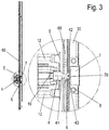
- FIG. 3 the fitting with the locking mechanism is shown in detail.
- the locking pin 4 protrudes from the housing 5 and engages through an opening on the locking element 6.
- the locking pin 4 has a tapered neck portion 41 and a widened head portion 42.
- the locking element 6 acts on the tapered neck portion 41 and thus secures the sliding door 3 against being pulled on.
- the locking element 6 is arranged on a bar 60, which is connected via a gear with the handle of the sliding door 3.
- At the head portion 42 is another magnet 43, which amplifies the attraction forces to the magnet 7. It is also possible to produce the locking bolt 4 made of metal and to dispense with a further magnet 43.
- a plate-shaped damping element 70 located between the end of the locking bolt 4 and the magnet 7 is a plate-shaped damping element 70, for example made of plastic or other elastic material that prevents loud striking noises when extending the locking bolt 4.
- the housing 5 with the locking bolt 4 has openings 12 in order to be able to fix fastening means, for example screws, on the frame profile 20.
- a guide is formed by a cavity, wherein the locking pin 4 is held on a plate 10.
- the locking pin 4 can be moved by two springs 11 in the retracted position, each spring 11 acts on the plate 10 and is held at the opposite end to a receptacle on the housing 5.
- the springs 11 thereby push the locking pin 4 into the retracted position so that, with sufficient clearance between the locking pin 4 and the magnet 7, the forces by the springs 11 are greater than the forces of attraction by the magnets 7 and 43.
- the locking pin 4 In the retracted position the locking pin 4 completely within the housing 5 and therefore does not appear disturbing in appearance.
- an adjusting mechanism may be provided which limits the maximum extension movement of the locking bolt 4.
- an adjustable stop can be provided on the housing 5.
- FIG. 5 the housing 5 is shown, which is insertable into a recess on the frame profile 20.
- the locking bolt 4 protrudes, which has an annular magnet 43 at the head portion.
- a tool such as a screwdriver to rotate the locking pin 4.
- the locking bolt 4 is connected at the opposite end via a thread with the plate 10, so that by rotating the locking bolt 4 whose position in the direction of movement of the locking bolt 4 is adjustable. Thereby, the maximum protruding position of the locking bolt 4 can be adjusted.
- annular magnet 43 instead of the annular magnet 43, one or more other magnets may be provided on the locking bolt 4.
- the locking bolt 4 is slidably mounted in the housing 5. It is of course possible to provide a cam guide or a pivoting movement for the locking pin 4 instead of a linear displaceability.
- the locking bolt 4 can be completely inserted into the housing 5. Alternatively, it is possible to move the locking bolt to a retracted position in which still protrudes a front portion of the locking bolt 4 of the frame section 20.
- FIG. 6 is a further embodiment of a fitting shown as it on a sliding door unit according to FIG. 1 can be installed.
- a grip element 15 is rotatably mounted in order to move the sliding door 3 from a lowered closed position to a raised open position.
- a drive rod 6 ' is coupled, which is displaceable upon rotation of the handle member 15 in order to effect unlocking or locking the sliding door 3.
- the handle element 15 may also be another actuator for unlocking or locking the sliding door 3 may be provided.
- a housing 5 On the drive rod 6 ', a housing 5 is fixed, on which a locking pin 4 is movably mounted.
- the housing 5 and the locking bolt 4 may be formed except for an additional locking pin 45 as in the previous embodiment, wherein the locking pin 4 is biased by a spring 11 in a retracted position.
- a plate 10 With the locking pin 4, a plate 10 is coupled, on which one end of each spring 11 is supported, while the opposite end supported on the housing 5 is.
- a chamber 50 is formed in which the locking pin 4 is slidably held with the plate 10.
- the locking pin 4 protrudes from the housing 5, wherein a thickened head portion 42 'engages in a housing.
- a guide track 17 is formed, which is penetrated by the tapered neck portion 41 of the locking bolt 4, so that the locking pin 4 is secured over the thickened head portion 42 against pulling out of the guide track 17 in the longitudinal direction of the locking bolt 4.
- the in FIG. 6 shown locked shooting position are or the locking pin 4 in the locking portion of the guide rail 17 and the sliding door 3 in a lowered position.
- the grip element 15 is pivoted, as shown in FIG FIG. 7 is shown.
- the drive rod 6 ' is moved, whereby the locking pin 4 are moved together with the housing 5 upwards.
- the locking bolt 4 moves along the guide track 17 on the housing 8 'and reaches a widened portion, on which the locking bolt 4 can be pulled out of the housing 8'.
- a magnet 7 is provided which exerts forces on the locking pin 4, so that it is arranged in the extended position and is not moved by the forces of the springs 11 in the retracted position.
- magnets are provided on the locking bolt 4 on the head portion 42, as explained in the preceding embodiment, the sliding door 3 is now in a raised and unlocked position.
- the locking bolt 4 moves away from the housing 8 'as shown in FIG FIG. 8 is shown. Due to the greater distance between the locking pin 4 and the magnet 7 in the housing 8 ', the magnetic forces relax, so that now the locking pin 4 is moved due to the force of the springs 11 in the retracted or retracted position. Thereby, the locking pin 4 is displaced in the chamber 50, wherein a locking pin 45 engages in an opening 81 on a locking element 80.
- the locking member 80 is fixed to a frame profile of the sliding door 3 and prevents a misoperation.
- the grip element 15 When the locking pin 4 is arranged in the retracted position, the grip element 15 can no longer be in the locked position from the unlocked position be pivoted, since the drive rod 6 'is blocked via the coupling between the locking pin 45 and the blocking element 80. If the sliding door 3 is moved from the opening position in the direction of the closed position, the gripping element 15 can not be pivoted, as long as the locking bolt 4 is arranged in the retracted position. Only when the locking pin 4 is pulled out by the magnetic forces through the magnet 7, as in FIG. 7 is shown, the locking pin 45 leaves the opening 81 in the locking element 80, so that the drive rod 6 'can be moved again to move the locking pin 4 along the housing 8' in the guide track 17.
- FIG. 9 the housing 8 'is shown, on which a locking bolt 4 can be locked.
- two openings 16 for fastening means, in particular screws, are provided in the box-shaped housing 8 '.
- the guide track 17 is recessed in the housing 8 'having a narrow locking portion and an unlocking portion 18 having a greater width than the locking portion. In the region of the unlocking section 18, the locking bolt 4 with the thickened head section 42 can be pulled out of the housing 8 '.
- a modified locking device can be provided which blocks an actuation of the handle element 15 of the sliding door lock when the locking bolt 4 is in a retracted position.
- FIGS. 6 to 8 two locking pin 4 with the drive rod 6 ', wherein the fitting may be formed only with a locking pin 4 or more than two locking pin 4.
- the sliding door is designed as a lift-and-slide door. It is also possible to dispense with lifting the sliding door and form this only as a sliding door.
Landscapes
- Wing Frames And Configurations (AREA)
Applications Claiming Priority (2)
| Application Number | Priority Date | Filing Date | Title |
|---|---|---|---|
| DE102016100747 | 2016-01-18 | ||
| DE102016119515.4A DE102016119515B4 (de) | 2016-01-18 | 2016-10-13 | Beschlag für eine Schiebetür und Schiebetüreinheit |
Publications (2)
| Publication Number | Publication Date |
|---|---|
| EP3192951A1 true EP3192951A1 (fr) | 2017-07-19 |
| EP3192951B1 EP3192951B1 (fr) | 2022-08-17 |
Family
ID=57471766
Family Applications (1)
| Application Number | Title | Priority Date | Filing Date |
|---|---|---|---|
| EP16202032.5A Active EP3192951B1 (fr) | 2016-01-18 | 2016-12-02 | Ferrure de porte coulissante, porte coulissante, procédé d'ouverture d'une porte coulissante et procédé de fermeture d'une porte coulissante |
Country Status (2)
| Country | Link |
|---|---|
| EP (1) | EP3192951B1 (fr) |
| PL (1) | PL3192951T3 (fr) |
Cited By (2)
| Publication number | Priority date | Publication date | Assignee | Title |
|---|---|---|---|---|
| IT201800004242A1 (it) * | 2018-04-05 | 2019-10-05 | Dispositivo di chiusura per infissi scorrevoli. | |
| DE102021211638B3 (de) | 2021-10-14 | 2022-12-15 | Roto Frank Fenster- und Türtechnologie GmbH | Fenster- oder Türverschluss im Schema D sowie Verfahren zum Öffnen des Fensters oder der Tür |
Citations (4)
| Publication number | Priority date | Publication date | Assignee | Title |
|---|---|---|---|---|
| AT372481B (de) * | 1982-03-19 | 1983-10-10 | Mayer & Co Riegel Beschlag | Verschluss fuer ein fenster oder eine tuer |
| DE202006008992U1 (de) * | 2006-06-06 | 2007-10-11 | Gebr. Willach Gmbh | Schiebetürbeschlag |
| US20140208651A1 (en) * | 2011-01-28 | 2014-07-31 | Assa Abloy Ip Ab | Intensive care unit door control system |
| EP2792828A2 (fr) * | 2013-04-17 | 2014-10-22 | Hoppe Ag | Dispositif de maintien en position fermée pour portes coulissantes et dispositif de fermeture pour portes coulissantes |
Family Cites Families (2)
| Publication number | Priority date | Publication date | Assignee | Title |
|---|---|---|---|---|
| DE10312269A1 (de) * | 2003-03-19 | 2004-09-30 | Drumm Gmbh | Magneto-mechanische Schließeinrichtung |
| CA2916844C (fr) * | 2013-07-29 | 2021-05-18 | Cavity Sliders Limited | Agencement de serrure |
-
2016
- 2016-12-02 PL PL16202032.5T patent/PL3192951T3/pl unknown
- 2016-12-02 EP EP16202032.5A patent/EP3192951B1/fr active Active
Patent Citations (4)
| Publication number | Priority date | Publication date | Assignee | Title |
|---|---|---|---|---|
| AT372481B (de) * | 1982-03-19 | 1983-10-10 | Mayer & Co Riegel Beschlag | Verschluss fuer ein fenster oder eine tuer |
| DE202006008992U1 (de) * | 2006-06-06 | 2007-10-11 | Gebr. Willach Gmbh | Schiebetürbeschlag |
| US20140208651A1 (en) * | 2011-01-28 | 2014-07-31 | Assa Abloy Ip Ab | Intensive care unit door control system |
| EP2792828A2 (fr) * | 2013-04-17 | 2014-10-22 | Hoppe Ag | Dispositif de maintien en position fermée pour portes coulissantes et dispositif de fermeture pour portes coulissantes |
Cited By (4)
| Publication number | Priority date | Publication date | Assignee | Title |
|---|---|---|---|---|
| IT201800004242A1 (it) * | 2018-04-05 | 2019-10-05 | Dispositivo di chiusura per infissi scorrevoli. | |
| WO2019193480A1 (fr) * | 2018-04-05 | 2019-10-10 | Mypro Research S.R.L. | Dispositif de fermeture pour portes/fenêtres coulissantes |
| DE102021211638B3 (de) | 2021-10-14 | 2022-12-15 | Roto Frank Fenster- und Türtechnologie GmbH | Fenster- oder Türverschluss im Schema D sowie Verfahren zum Öffnen des Fensters oder der Tür |
| EP4170117A1 (fr) | 2021-10-14 | 2023-04-26 | Roto Frank Fenster- und Türtechnologie GmbH | Serrure de fenêtre ou de porte selon le schéma d et procédé d'ouverture de la fenêtre ou de la porte |
Also Published As
| Publication number | Publication date |
|---|---|
| EP3192951B1 (fr) | 2022-08-17 |
| PL3192951T3 (pl) | 2022-12-19 |
Similar Documents
| Publication | Publication Date | Title |
|---|---|---|
| DE102016119515B4 (de) | Beschlag für eine Schiebetür und Schiebetüreinheit | |
| EP3102759B1 (fr) | Ferrure d'un battant de fenêtres ou de portes, au moins relevable et coulissant | |
| EP2105556A1 (fr) | Dispositif de verrouillage | |
| EP3192951B1 (fr) | Ferrure de porte coulissante, porte coulissante, procédé d'ouverture d'une porte coulissante et procédé de fermeture d'une porte coulissante | |
| EP3296493A1 (fr) | Système support pour porte coulissante | |
| EP2957697A1 (fr) | Dispositif d'insertion pour portes coulissantes et fenêtre ou porte | |
| EP3109385B1 (fr) | Dispositif de fermeture de porte comprenant un battant de porte unique ou en plusieurs parties | |
| DE19652599C2 (de) | Ent- und Verriegelung für eine einen Standflügel und einen Gangflügel aufweisende Tür | |
| DE102015000606A1 (de) | Verriegelungsvorrichtung für einen schwenkbar gelagerten Flügel | |
| DE102014118665A1 (de) | Einzugsvorrichtung für ein Schiebefenster oder eine Schiebetür | |
| DE102007025723B3 (de) | Kupplungseinheit für ein Garagentor, insbesondere Kipp-, Schwenk- oder Sektionaltor | |
| EP3859107B1 (fr) | Porte coulissante | |
| EP3034728B1 (fr) | Dispositif limiteur d'ouverture | |
| EP3208407B1 (fr) | Verrou dote d'un dispositif de securite | |
| AT520645A4 (de) | Verriegelungsvorrichtung für eine Tür, insbesondere Schiebetür | |
| DE102018200582B3 (de) | Teleskopschiebetürsystem | |
| EP0846825B1 (fr) | Dispositif de verrouillage pour un vantail de porte amovible dans un châssis | |
| EP3511493B1 (fr) | Système de porte coulissante | |
| DE202008004659U1 (de) | Öffnungsbegrenzung für ein Fenster oder eine Tür | |
| DE10125324A1 (de) | Adapter für Schubladen und/oder Türen aufweisende Möbel | |
| EP3444417B1 (fr) | Système de stockage pour ouvertures de bâtiment | |
| EP2674554A2 (fr) | Serrure à pêne basculant | |
| EP2574716B1 (fr) | Porte ou fenêtre coulissante avec un dispositif d'aération et procédé de travail | |
| DE102007010209A1 (de) | Antriebsvorrichtung | |
| DE202008013553U1 (de) | Beschlag für einen Flügel von Fenstern oder Türen |
Legal Events
| Date | Code | Title | Description |
|---|---|---|---|
| PUAI | Public reference made under article 153(3) epc to a published international application that has entered the european phase |
Free format text: ORIGINAL CODE: 0009012 |
|
| STAA | Information on the status of an ep patent application or granted ep patent |
Free format text: STATUS: THE APPLICATION HAS BEEN PUBLISHED |
|
| AK | Designated contracting states |
Kind code of ref document: A1 Designated state(s): AL AT BE BG CH CY CZ DE DK EE ES FI FR GB GR HR HU IE IS IT LI LT LU LV MC MK MT NL NO PL PT RO RS SE SI SK SM TR |
|
| AX | Request for extension of the european patent |
Extension state: BA ME |
|
| STAA | Information on the status of an ep patent application or granted ep patent |
Free format text: STATUS: REQUEST FOR EXAMINATION WAS MADE |
|
| 17P | Request for examination filed |
Effective date: 20180104 |
|
| RBV | Designated contracting states (corrected) |
Designated state(s): AL AT BE BG CH CY CZ DE DK EE ES FI FR GB GR HR HU IE IS IT LI LT LU LV MC MK MT NL NO PL PT RO RS SE SI SK SM TR |
|
| STAA | Information on the status of an ep patent application or granted ep patent |
Free format text: STATUS: EXAMINATION IS IN PROGRESS |
|
| 17Q | First examination report despatched |
Effective date: 20210322 |
|
| STAA | Information on the status of an ep patent application or granted ep patent |
Free format text: STATUS: EXAMINATION IS IN PROGRESS |
|
| RIC1 | Information provided on ipc code assigned before grant |
Ipc: E05B 63/24 20060101ALN20220407BHEP Ipc: E05B 15/02 20060101ALI20220407BHEP Ipc: E05B 65/08 20060101AFI20220407BHEP |
|
| GRAP | Despatch of communication of intention to grant a patent |
Free format text: ORIGINAL CODE: EPIDOSNIGR1 |
|
| STAA | Information on the status of an ep patent application or granted ep patent |
Free format text: STATUS: GRANT OF PATENT IS INTENDED |
|
| INTG | Intention to grant announced |
Effective date: 20220513 |
|
| RIN1 | Information on inventor provided before grant (corrected) |
Inventor name: BEISSNER, MARTIN Inventor name: MUEGGE, DIRK Inventor name: LISS, CONSTANTIN |
|
| GRAS | Grant fee paid |
Free format text: ORIGINAL CODE: EPIDOSNIGR3 |
|
| GRAA | (expected) grant |
Free format text: ORIGINAL CODE: 0009210 |
|
| STAA | Information on the status of an ep patent application or granted ep patent |
Free format text: STATUS: THE PATENT HAS BEEN GRANTED |
|
| AK | Designated contracting states |
Kind code of ref document: B1 Designated state(s): AL AT BE BG CH CY CZ DE DK EE ES FI FR GB GR HR HU IE IS IT LI LT LU LV MC MK MT NL NO PL PT RO RS SE SI SK SM TR |
|
| REG | Reference to a national code |
Ref country code: CH Ref legal event code: EP |
|
| REG | Reference to a national code |
Ref country code: DE Ref legal event code: R096 Ref document number: 502016015176 Country of ref document: DE |
|
| REG | Reference to a national code |
Ref country code: IE Ref legal event code: FG4D Free format text: LANGUAGE OF EP DOCUMENT: GERMAN |
|
| REG | Reference to a national code |
Ref country code: AT Ref legal event code: REF Ref document number: 1512286 Country of ref document: AT Kind code of ref document: T Effective date: 20220915 |
|
| REG | Reference to a national code |
Ref country code: NL Ref legal event code: MP Effective date: 20220817 |
|
| REG | Reference to a national code |
Ref country code: LT Ref legal event code: MG9D |
|
| PG25 | Lapsed in a contracting state [announced via postgrant information from national office to epo] |
Ref country code: SE Free format text: LAPSE BECAUSE OF FAILURE TO SUBMIT A TRANSLATION OF THE DESCRIPTION OR TO PAY THE FEE WITHIN THE PRESCRIBED TIME-LIMIT Effective date: 20220817 Ref country code: RS Free format text: LAPSE BECAUSE OF FAILURE TO SUBMIT A TRANSLATION OF THE DESCRIPTION OR TO PAY THE FEE WITHIN THE PRESCRIBED TIME-LIMIT Effective date: 20220817 Ref country code: PT Free format text: LAPSE BECAUSE OF FAILURE TO SUBMIT A TRANSLATION OF THE DESCRIPTION OR TO PAY THE FEE WITHIN THE PRESCRIBED TIME-LIMIT Effective date: 20221219 Ref country code: NO Free format text: LAPSE BECAUSE OF FAILURE TO SUBMIT A TRANSLATION OF THE DESCRIPTION OR TO PAY THE FEE WITHIN THE PRESCRIBED TIME-LIMIT Effective date: 20221117 Ref country code: NL Free format text: LAPSE BECAUSE OF FAILURE TO SUBMIT A TRANSLATION OF THE DESCRIPTION OR TO PAY THE FEE WITHIN THE PRESCRIBED TIME-LIMIT Effective date: 20220817 Ref country code: LV Free format text: LAPSE BECAUSE OF FAILURE TO SUBMIT A TRANSLATION OF THE DESCRIPTION OR TO PAY THE FEE WITHIN THE PRESCRIBED TIME-LIMIT Effective date: 20220817 Ref country code: LT Free format text: LAPSE BECAUSE OF FAILURE TO SUBMIT A TRANSLATION OF THE DESCRIPTION OR TO PAY THE FEE WITHIN THE PRESCRIBED TIME-LIMIT Effective date: 20220817 Ref country code: FI Free format text: LAPSE BECAUSE OF FAILURE TO SUBMIT A TRANSLATION OF THE DESCRIPTION OR TO PAY THE FEE WITHIN THE PRESCRIBED TIME-LIMIT Effective date: 20220817 Ref country code: ES Free format text: LAPSE BECAUSE OF FAILURE TO SUBMIT A TRANSLATION OF THE DESCRIPTION OR TO PAY THE FEE WITHIN THE PRESCRIBED TIME-LIMIT Effective date: 20220817 |
|
| PG25 | Lapsed in a contracting state [announced via postgrant information from national office to epo] |
Ref country code: IS Free format text: LAPSE BECAUSE OF FAILURE TO SUBMIT A TRANSLATION OF THE DESCRIPTION OR TO PAY THE FEE WITHIN THE PRESCRIBED TIME-LIMIT Effective date: 20221217 Ref country code: HR Free format text: LAPSE BECAUSE OF FAILURE TO SUBMIT A TRANSLATION OF THE DESCRIPTION OR TO PAY THE FEE WITHIN THE PRESCRIBED TIME-LIMIT Effective date: 20220817 Ref country code: GR Free format text: LAPSE BECAUSE OF FAILURE TO SUBMIT A TRANSLATION OF THE DESCRIPTION OR TO PAY THE FEE WITHIN THE PRESCRIBED TIME-LIMIT Effective date: 20221118 |
|
| PG25 | Lapsed in a contracting state [announced via postgrant information from national office to epo] |
Ref country code: SM Free format text: LAPSE BECAUSE OF FAILURE TO SUBMIT A TRANSLATION OF THE DESCRIPTION OR TO PAY THE FEE WITHIN THE PRESCRIBED TIME-LIMIT Effective date: 20220817 Ref country code: RO Free format text: LAPSE BECAUSE OF FAILURE TO SUBMIT A TRANSLATION OF THE DESCRIPTION OR TO PAY THE FEE WITHIN THE PRESCRIBED TIME-LIMIT Effective date: 20220817 Ref country code: DK Free format text: LAPSE BECAUSE OF FAILURE TO SUBMIT A TRANSLATION OF THE DESCRIPTION OR TO PAY THE FEE WITHIN THE PRESCRIBED TIME-LIMIT Effective date: 20220817 Ref country code: CZ Free format text: LAPSE BECAUSE OF FAILURE TO SUBMIT A TRANSLATION OF THE DESCRIPTION OR TO PAY THE FEE WITHIN THE PRESCRIBED TIME-LIMIT Effective date: 20220817 |
|
| REG | Reference to a national code |
Ref country code: DE Ref legal event code: R097 Ref document number: 502016015176 Country of ref document: DE |
|
| PG25 | Lapsed in a contracting state [announced via postgrant information from national office to epo] |
Ref country code: SK Free format text: LAPSE BECAUSE OF FAILURE TO SUBMIT A TRANSLATION OF THE DESCRIPTION OR TO PAY THE FEE WITHIN THE PRESCRIBED TIME-LIMIT Effective date: 20220817 Ref country code: EE Free format text: LAPSE BECAUSE OF FAILURE TO SUBMIT A TRANSLATION OF THE DESCRIPTION OR TO PAY THE FEE WITHIN THE PRESCRIBED TIME-LIMIT Effective date: 20220817 |
|
| PGFP | Annual fee paid to national office [announced via postgrant information from national office to epo] |
Ref country code: PL Payment date: 20230301 Year of fee payment: 8 Ref country code: IT Payment date: 20221230 Year of fee payment: 7 |
|
| PLBE | No opposition filed within time limit |
Free format text: ORIGINAL CODE: 0009261 |
|
| STAA | Information on the status of an ep patent application or granted ep patent |
Free format text: STATUS: NO OPPOSITION FILED WITHIN TIME LIMIT |
|
| PG25 | Lapsed in a contracting state [announced via postgrant information from national office to epo] |
Ref country code: AL Free format text: LAPSE BECAUSE OF FAILURE TO SUBMIT A TRANSLATION OF THE DESCRIPTION OR TO PAY THE FEE WITHIN THE PRESCRIBED TIME-LIMIT Effective date: 20220817 |
|
| 26N | No opposition filed |
Effective date: 20230519 |
|
| REG | Reference to a national code |
Ref country code: CH Ref legal event code: PL |
|
| GBPC | Gb: european patent ceased through non-payment of renewal fee |
Effective date: 20221202 |
|
| REG | Reference to a national code |
Ref country code: BE Ref legal event code: MM Effective date: 20221231 |
|
| PG25 | Lapsed in a contracting state [announced via postgrant information from national office to epo] |
Ref country code: SI Free format text: LAPSE BECAUSE OF FAILURE TO SUBMIT A TRANSLATION OF THE DESCRIPTION OR TO PAY THE FEE WITHIN THE PRESCRIBED TIME-LIMIT Effective date: 20220817 Ref country code: LU Free format text: LAPSE BECAUSE OF NON-PAYMENT OF DUE FEES Effective date: 20221202 |
|
| PG25 | Lapsed in a contracting state [announced via postgrant information from national office to epo] |
Ref country code: LI Free format text: LAPSE BECAUSE OF NON-PAYMENT OF DUE FEES Effective date: 20221231 Ref country code: IE Free format text: LAPSE BECAUSE OF NON-PAYMENT OF DUE FEES Effective date: 20221202 Ref country code: GB Free format text: LAPSE BECAUSE OF NON-PAYMENT OF DUE FEES Effective date: 20221202 Ref country code: CH Free format text: LAPSE BECAUSE OF NON-PAYMENT OF DUE FEES Effective date: 20221231 |
|
| PG25 | Lapsed in a contracting state [announced via postgrant information from national office to epo] |
Ref country code: FR Free format text: LAPSE BECAUSE OF NON-PAYMENT OF DUE FEES Effective date: 20221231 Ref country code: BE Free format text: LAPSE BECAUSE OF NON-PAYMENT OF DUE FEES Effective date: 20221231 |
|
| PGFP | Annual fee paid to national office [announced via postgrant information from national office to epo] |
Ref country code: DE Payment date: 20230403 Year of fee payment: 8 |
|
| REG | Reference to a national code |
Ref country code: AT Ref legal event code: MM01 Ref document number: 1512286 Country of ref document: AT Kind code of ref document: T Effective date: 20221202 |
|
| PG25 | Lapsed in a contracting state [announced via postgrant information from national office to epo] |
Ref country code: HU Free format text: LAPSE BECAUSE OF FAILURE TO SUBMIT A TRANSLATION OF THE DESCRIPTION OR TO PAY THE FEE WITHIN THE PRESCRIBED TIME-LIMIT; INVALID AB INITIO Effective date: 20161202 |
|
| PG25 | Lapsed in a contracting state [announced via postgrant information from national office to epo] |
Ref country code: AT Free format text: LAPSE BECAUSE OF NON-PAYMENT OF DUE FEES Effective date: 20221202 |
|
| PG25 | Lapsed in a contracting state [announced via postgrant information from national office to epo] |
Ref country code: CY Free format text: LAPSE BECAUSE OF FAILURE TO SUBMIT A TRANSLATION OF THE DESCRIPTION OR TO PAY THE FEE WITHIN THE PRESCRIBED TIME-LIMIT Effective date: 20220817 Ref country code: AT Free format text: LAPSE BECAUSE OF NON-PAYMENT OF DUE FEES Effective date: 20221202 |