EP3192648A1 - Régulation de température pendant la vulcanisation d'un pneumatique - Google Patents
Régulation de température pendant la vulcanisation d'un pneumatique Download PDFInfo
- Publication number
- EP3192648A1 EP3192648A1 EP16305029.7A EP16305029A EP3192648A1 EP 3192648 A1 EP3192648 A1 EP 3192648A1 EP 16305029 A EP16305029 A EP 16305029A EP 3192648 A1 EP3192648 A1 EP 3192648A1
- Authority
- EP
- European Patent Office
- Prior art keywords
- temperature
- heating medium
- tire
- cavity
- bladder
- Prior art date
- Legal status (The legal status is an assumption and is not a legal conclusion. Google has not performed a legal analysis and makes no representation as to the accuracy of the status listed.)
- Granted
Links
- 238000004073 vulcanization Methods 0.000 title claims abstract description 43
- 230000001105 regulatory effect Effects 0.000 title claims description 5
- 238000010438 heat treatment Methods 0.000 claims abstract description 114
- 238000000034 method Methods 0.000 claims description 26
- 230000004907 flux Effects 0.000 claims description 13
- 238000012544 monitoring process Methods 0.000 claims description 13
- 238000000605 extraction Methods 0.000 claims description 8
- IJGRMHOSHXDMSA-UHFFFAOYSA-N Atomic nitrogen Chemical compound N#N IJGRMHOSHXDMSA-UHFFFAOYSA-N 0.000 claims description 7
- 238000004891 communication Methods 0.000 claims description 7
- 230000000694 effects Effects 0.000 claims description 7
- 230000007423 decrease Effects 0.000 claims description 6
- 239000012530 fluid Substances 0.000 claims description 5
- 230000004913 activation Effects 0.000 claims description 4
- 229910052757 nitrogen Inorganic materials 0.000 claims description 4
- 230000009849 deactivation Effects 0.000 claims description 3
- 230000004044 response Effects 0.000 claims description 3
- 238000004364 calculation method Methods 0.000 claims description 2
- 230000000977 initiatory effect Effects 0.000 claims 1
- 230000008569 process Effects 0.000 description 10
- 238000012546 transfer Methods 0.000 description 10
- 230000001276 controlling effect Effects 0.000 description 5
- 238000012795 verification Methods 0.000 description 5
- 239000012528 membrane Substances 0.000 description 4
- 238000000265 homogenisation Methods 0.000 description 3
- 238000012986 modification Methods 0.000 description 3
- 230000004048 modification Effects 0.000 description 3
- 238000012545 processing Methods 0.000 description 3
- 239000012080 ambient air Substances 0.000 description 2
- 230000005540 biological transmission Effects 0.000 description 2
- 238000002474 experimental method Methods 0.000 description 2
- QJGQUHMNIGDVPM-UHFFFAOYSA-N nitrogen group Chemical group [N] QJGQUHMNIGDVPM-UHFFFAOYSA-N 0.000 description 2
- 238000004088 simulation Methods 0.000 description 2
- 238000012360 testing method Methods 0.000 description 2
- RYGMFSIKBFXOCR-UHFFFAOYSA-N Copper Chemical compound [Cu] RYGMFSIKBFXOCR-UHFFFAOYSA-N 0.000 description 1
- 230000006978 adaptation Effects 0.000 description 1
- 238000007792 addition Methods 0.000 description 1
- XAGFODPZIPBFFR-UHFFFAOYSA-N aluminium Chemical compound [Al] XAGFODPZIPBFFR-UHFFFAOYSA-N 0.000 description 1
- 229910052782 aluminium Inorganic materials 0.000 description 1
- 239000011324 bead Substances 0.000 description 1
- 229920005549 butyl rubber Polymers 0.000 description 1
- 230000001413 cellular effect Effects 0.000 description 1
- 230000000295 complement effect Effects 0.000 description 1
- 239000004020 conductor Substances 0.000 description 1
- 229910052802 copper Inorganic materials 0.000 description 1
- 239000010949 copper Substances 0.000 description 1
- 238000012937 correction Methods 0.000 description 1
- 238000004132 cross linking Methods 0.000 description 1
- 238000013481 data capture Methods 0.000 description 1
- 230000001419 dependent effect Effects 0.000 description 1
- 238000001514 detection method Methods 0.000 description 1
- 238000010586 diagram Methods 0.000 description 1
- 229910001873 dinitrogen Inorganic materials 0.000 description 1
- 239000013013 elastic material Substances 0.000 description 1
- 229920001971 elastomer Polymers 0.000 description 1
- 239000000806 elastomer Substances 0.000 description 1
- 238000005516 engineering process Methods 0.000 description 1
- 230000006698 induction Effects 0.000 description 1
- 238000007726 management method Methods 0.000 description 1
- 239000000463 material Substances 0.000 description 1
- 238000005259 measurement Methods 0.000 description 1
- 230000007246 mechanism Effects 0.000 description 1
- 239000000203 mixture Substances 0.000 description 1
- 238000000465 moulding Methods 0.000 description 1
- 230000006855 networking Effects 0.000 description 1
- 230000003287 optical effect Effects 0.000 description 1
- 230000035515 penetration Effects 0.000 description 1
- 239000000758 substrate Substances 0.000 description 1
- 238000009423 ventilation Methods 0.000 description 1
Images

Classifications
-
- B—PERFORMING OPERATIONS; TRANSPORTING
- B29—WORKING OF PLASTICS; WORKING OF SUBSTANCES IN A PLASTIC STATE IN GENERAL
- B29D—PRODUCING PARTICULAR ARTICLES FROM PLASTICS OR FROM SUBSTANCES IN A PLASTIC STATE
- B29D30/00—Producing pneumatic or solid tyres or parts thereof
- B29D30/06—Pneumatic tyres or parts thereof (e.g. produced by casting, moulding, compression moulding, injection moulding, centrifugal casting)
- B29D30/0601—Vulcanising tyres; Vulcanising presses for tyres
- B29D30/0662—Accessories, details or auxiliary operations
- B29D2030/0666—Heating by using fluids
- B29D2030/0667—Circulating the fluids, e.g. introducing and removing them into and from the moulds; devices therefor
- B29D2030/0669—Circulating the fluids, e.g. introducing and removing them into and from the moulds; devices therefor the fluids being circulated by a turbine type pump associated with the mould, e.g. positioned in the mould
-
- B—PERFORMING OPERATIONS; TRANSPORTING
- B29—WORKING OF PLASTICS; WORKING OF SUBSTANCES IN A PLASTIC STATE IN GENERAL
- B29D—PRODUCING PARTICULAR ARTICLES FROM PLASTICS OR FROM SUBSTANCES IN A PLASTIC STATE
- B29D30/00—Producing pneumatic or solid tyres or parts thereof
- B29D30/06—Pneumatic tyres or parts thereof (e.g. produced by casting, moulding, compression moulding, injection moulding, centrifugal casting)
- B29D30/0601—Vulcanising tyres; Vulcanising presses for tyres
- B29D30/0662—Accessories, details or auxiliary operations
- B29D2030/0675—Controlling the vulcanization processes
- B29D2030/0677—Controlling temperature differences
-
- B—PERFORMING OPERATIONS; TRANSPORTING
- B29—WORKING OF PLASTICS; WORKING OF SUBSTANCES IN A PLASTIC STATE IN GENERAL
- B29D—PRODUCING PARTICULAR ARTICLES FROM PLASTICS OR FROM SUBSTANCES IN A PLASTIC STATE
- B29D30/00—Producing pneumatic or solid tyres or parts thereof
- B29D30/06—Pneumatic tyres or parts thereof (e.g. produced by casting, moulding, compression moulding, injection moulding, centrifugal casting)
- B29D30/0601—Vulcanising tyres; Vulcanising presses for tyres
- B29D30/0654—Flexible cores therefor, e.g. bladders, bags, membranes, diaphragms
Definitions
- the presently disclosed invention is generally directed to tire vulcanization. More particularly, the presently disclosed invention is directed to capture and control of a heating medium temperature during a tire cure cycle.
- one or more tire vulcanizing systems may be employed for use with a tire mold.
- a principal characteristic of certain vulcanization systems is to place a system of heating and ventilation at the heart of an electric vulcanization system and thus provide a heated medium.
- heating medium a high-temperature and high-pressure heating medium
- a bladder i.e., one formed from an elastic material such as butyl rubber
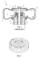
- System 10 includes a fluid-tight enclosure 12 that receives a supply of a pressurized heating medium (e.g., nitrogen gas).
- the enclosure has a cavity 14 formed by a pair of plates 16, 18 connected by a bladder 20 with an operating shaft 22 effecting axial movement of at least one plate (as shown, plate 16 is axially displaceable).
- a heater 24 having one or more heating elements 24a heats the heating medium. It is understood that heater 24 may be selected from any amenable heating means, including but not limited to resistors, induction elements and the like.
- Both heater 24 and fan 26 are enveloped within cavity 14 and therefore immersed wholly in the heating medium.
- Heater 24 is disposed in a fluid path that is in communication with both cavity 14 and at least one conduit 32 through which the heating medium is introduced into, and/or extracted from, cavity 14.
- the heating medium traverses heating elements 24a before egress along an exit path 26a from fan 26 into the fluid-tight enclosure.
- the delivery of the heating medium provides sufficient energy to bladder 20 for deep penetration of tread pattern elements of the tire mold (not shown) into tire P.
- Tire P is thereby heated to a vulcanizing temperature through bladder 20 and simultaneously pressed in a molding direction. Exemplary embodiments of such systems and demonstrations of their use are disclosed by co-owned EP Patent No.
- the heating medium is subject to rotation under the effect of relative movement imparted by fan 26.
- the heating fluid attains sufficient tangential speed ⁇ within the cavity so as to ensure a good thermal exchange with the internal surface of bladder 20.
- the heating medium exhibits a speed ⁇ (see FIG. 1 ) that derives the necessary vulcanization energy from heater 24 and delivers it to an internal surface of bladder 20.
- the invention provides a tire vulcanizing system (100) for regulating a temperature of a heating medium.
- the system (100) includes a bladder (120) disposed inside a tire (P') to be vulcanized and at least partially delineating a cavity (114) in which a heating medium circulates.
- a fan (126) and a heater (124) are immersed in the heating medium, and the heater has one or more heating elements (124a) that provide energy to the heating medium traversing thereover before egress along an exit path (126a).
- At least one temperature sensor (150) is disposed along the exit path and configured to detect a temperature of the heating medium in the cavity (114) and to generate one or more temperature signals indicative of detected heating medium temperature in the cavity.
- a monitoring system receives the one or more temperature signals and sends one or more commensurate commands to adjust the heating medium temperature in the cavity during a curing cycle.
- the monitoring system commands an increase of the heater output.
- the monitoring system commands a decrease of the heater output.
- the temperature sensor (150) is mounted on or near the stationary plate (118) immediately proximate an egress from which the fan delivers the heating medium to the exit path (126a).
- the temperature sensor (150) can be configured to detect the temperature of the heating medium at regular predetermined time intervals.
- the monitoring system can be configured to delay activation or deactivation of the heater (124) until an identified temperature threshold is maintained for a pre-set number of time intervals.
- the invention also includes a method of detecting and adjusting a temperature of a heating medium in a fluid-tight enclosure in a tire vulcanization system as disclosed. In some embodiments, the method includes, based upon an energy balance to define the amount of energy to be sent by the vulcanization system (100) in advance of a subsequent curing cycle, detecting a heating medium temperature in the cavity (114) during a current curing cycle.
- the energy required to cure the tire being vulcanized is calculated as a function of at least the energy to be supplied for vulcanization of an inner tire surface, energy lost upon opening the mold between the current curing cycle and a subsequent curing cycle and energy lost by the vulcanization system during curing.
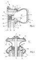
- FIGS. 3 and 4 show an exemplary tire vulcanization system 100 having many of the characteristics of system 10 shown in FIG. 1 .
- Vulcanization system 100 includes an axially movable plate 116 and a stationary plate 118 connected by a flexible bladder or curing membrane 120.
- Counterplates 117, 119 anchor bladder 120 to respective plates 116, 118 along a circumference thereof.
- Bladder 120 and plates 116, 118 together delineate a fluid-tight enclosure 112 having a cavity 114 for containing a heating medium under pressure (e.g., nitrogen).
- Bladder 120 cooperates in a known manner with a rigid tire mold (not shown) intended to form an outer tire shape and sculpture.
- a heater 124 is enveloped within cavity 114 and therefore immersed wholly in the heating medium during operation of system 100.
- Heater 124 is shown as a coil member having heating elements 124a generally formed in an annular shape, although it is understood that heater 124 may be selected from known heater mechanisms that are amenable to practice with the presently disclosed invention.
- Annular heating elements 124a are amenable to operation with a fan 126 having a plurality of blades 126b and a diametrical extent 126c.
- One or more blades 126b may have a high thermal conductive material at least partially integrated therewith, including but not limited to copper, aluminum and comparable and equivalent materials.
- a power source (such as an electric power source, not shown) that is in communication with heater 124 and fan 126 ensures uninterrupted control and operation of both elements within cavity 114.
- a central portion of enclosure 112 includes an operating shaft 122 that is rotatable relative to fixed mold 123 along an axis of revolution X-X' of the enclosure.
- Operating shaft 122 effects exemplary axial movement of plate 116 between a vulcanization position in which bladder 120 abuts an inner wall surface P s ' of tire P' (see FIG. 3 ) and an extraction position in which bladder 120 collapses (see FIG. 4 ).
- Rotor 130 effects circumferential rotation of a substrate 125 supporting fan 126. As is known in the art, rotor 130 sufficiently actuates fan blades 126b so as to impart a proscribed tangential velocity to the ejected heating medium.
- conduits 132 that are delineated in a stationary housing body 134 introduce pressurized heating medium into cavity 114.
- the heating medium is introduced into the cavity as needed (e.g., continuously or periodically) to maintain sufficient heat transfer along bladder 120 and wall 120a thereof.
- a valve (not shown) may be provided for automatic introduction and extraction of the heating medium.
- the heating medium is supplied from a heating medium supply (not shown) as is known in the art. Such heating medium supply may optionally include a preheating device that previously heats the heating medium prior to introduction thereof in cavity 114.
- conduit 132 may include one or more conduits that are also employed for the extraction of the heating medium upon termination of a curing cycle.
- the heating medium may be selected from a plurality of heating media amenable to use with a vulcanization system as presently described.
- the heating medium is nitrogen which exhibits negligible interdependence between pressure and temperature.
- the heating medium is nitrogen (or an equivalent thereof), independent control of the temperature of the heating medium is possible.
- the heating medium Upon actuation of fan 126, the heating medium is drawn through a central portion thereof, traverses heating elements 124a and is ejected along exit path 126a into cavity 114.
- At least one heating medium temperature sensor 150 (e.g., a thermocouple or equivalent thereof) is disposed intermediate housing body 134 and diametrical extent 126c.
- temperature sensor 150 is mounted on stationary plate 118 immediately proximate an egress from which fan 126 delivers the heating medium to exit path 126a.
- Temperature sensor 150 is configured to detect a temperature of the heating medium in cavity 114 and generates one or more temperature signals indicative of the detected temperature. It is contemplated that temperature sensor 150 may capture the heating medium temperature continuously (e.g., at each instant while a green tire is subject to the pressurized heating medium) or at regular predetermined time intervals.
- bladder 120 under the effect of the pressure of the heating medium, is in a deployed position pressed along inner wall surface P s ' of tire P'.
- axial movement of plate 116 is effected within pre-defined limits (e.g., in the direction indicated by arrow A) such that bladder 120 collapses toward the central portion of fan 126 (e.g., in order to free space for the passage of a bead).
- Collapse of bladder 120 positions the bladder in a ready state for a subsequent cure cycle without contacting blades 126b or temperature sensor 150.
- the positioning of temperature sensor 150 therefore not only ensures effective temperature data capture throughout a curing cycle; it also protects the sensor from damage during extraction and preserves uninterrupted operability of the sensor for multiple curing cycles.
- Temperature sensor 150 may be coupled to a monitoring system (not shown) that is configured to receive the temperature signals generated thereby.
- the monitoring system generates one or more control signals in response to the temperatures detected by temperature sensor 150. Such control signals are used to command the heater.
- the monitoring system thus receives the temperature data signals and sends a commensurate heating instruction to heater 124 on the basis of the received temperature data, the desired temperature of the heating medium, the heating time of the heating medium and other factors.
- factors are typically set up by a pre-established cycle that has been obtained from observed experimental data. In the art, it is generally understood that agreement between theory and experiment is very good.
- the applicable temperature, pressure and mold residence time can be thus regulated (e.g., via on-line control) to enable different elastomer compositions to attains a desired crosslinking degree.
- temperature sensor 150 captures the temperature of the heating medium supplied to cavity 114, therefore providing a pertinent representation of the temperature of the heating medium along inner wall surface 120a of bladder 120.
- heat flux may be controllably increased during a current curing cycle to ensure sufficient heat flux for vulcanization upon commencement of a subsequent curing cycle.
- the sensed heating medium temperature may therefore be relied upon in one or more processes for optimizing the transmission of energy by controlling the combination of heater 124 and fan 126.
- Opened loop and closed loop control modes can be used for controlling heater 124.
- An opened loop control mode is based upon energy control. In this mode, it necessary to realize an energy balance of vulcanization system 100 and thereby define the amount of energy to send to heater 124 prior to curing. This amount of energy is computed according to the physical characteristics of the green tire, the energy losses realized during curing and the energy losses realized during press opening. Some adjustments can be done during the curing, including a power adjustment according to the opening duration of the press and an additional adjustment according to the heating medium temperature that is measured during a previous curing.
- temperature sensor 150 may be employed.
- the energy that is needed for vulcanization of a tire is the energy that carries the tire from its initial temperature (e.g., ambient temperature) to its desired vulcanization temperature (e.g., as defined by applicable curing laws).
- This energy is supplied internally by the heating medium and externally by the mold. Based upon experience with multiple curing presses and confirmed by tests carried out on electrical presses, it is observed that the external energy contribution comprises up to about two-thirds of this energy and the internal contribution comprises up to about one-third.
- System 100 includes axially movable plate 116 in contact with ambient air and stationary plate 118 having no contact with ambient air.
- the thermal flux (in W) realized at the housing body can be calculated at each instant of the duration under pressure.
- the thermal flux is deemed constant along stationary plate 118, while the thermal flux realized at housing body 134 decreases at the same rate as the temperature thereof.
- the thermal flux that exits the mechanical parts of the vulcanization system 100 for the duration under pressure may thus be expressed in terms of initial and ambient temperatures around the housing body.
- the power that is consumed by rotor 130 remains essentially constant in that it is not dependent on the size and shape of a tire's internal cavity.
- the energy supplied by rotor 130 can be readily determined as a relationship between the consumed power and the length of the duration under pressure.
- the pendency of the duration under pressure may be observed at distinct stages during each of which the total energy to be supplied by the heater may be calculated and adjusted.
- activation and control of heater 124 may be realized in a phase during which the energy is transferred toward the tire upon commencement of the duration under pressure.
- stability of the heating medium temperature is ensured by capturing such temperature during the duration under pressure.
- a rise in the heating medium temperature has a duration that is measured from an initial time. Upon commencement of the duration under pressure, the heating medium temperature falls quickly and settles at a limit within a predictable temperature limit. Thus, power loss can be predicted and the heater output adjusted accordingly by adjusting the heater supply voltage.
- An optional correction or adjustment may be calculated in which the coefficient of exchange by forced convection h is presumed to be, on average, twice as low at a predicted elapsed time of the duration under pressure as compared with a remainder of the duration under pressure.
- the presently disclosed method during a phase of the elapsed time that is necessary for the introduction of power that is twice as large as that introduced during the subsequent remainder of the duration under pressure.
- the durations of elapsed time can be adjusted to ensure that the power realized does not surpass a maximum power of the heater. For example, in practice, a limit of 0.90 can be established so as to ensure a power reserve.
- Activation of heater 124 ceases and the system is permitted to homogenize until the end of the duration under pressure, at which time the heating medium settles in a final temperature range.
- the diminution of the heating medium temperature is linked to the transfer of energy toward the tire and to energy losses from the system. For example, upon deactivation of the heater, the pressure of the heating medium in bladder 120 may be low, thereby resulting in correspondingly low heat exchange.
- An error calculation may be performed in an experimental model or simulation such that the power levels are adjusted to compensate for this captured temperature value.
- the presently disclosed process enables reliable and repeatable power predictions and thereby permits management of cure while the vulcanization system is in a stabilized state (i.e., the predicted energy ensures cure of the tire and equally compensates for energy losses). It is understood that different phases of controlling a heater throughout a duration under pressure can be effected for any tire size and type, as would be understood by a skilled person.
- the objective is to induce the requisite temperature at the inner wall 120a of the bladder 120.
- Temperature sensor 150 is used to measure and control the temperature at the inner wall 120a of the bladder 120.
- the block diagram of FIG. 5 represents an exemplary programmable control loop.
- the setpoint temperature Tc level and duration are defined by experiment. This duration can be inferior or equal to the duration under pressure.
- This control may be realized by an exemplary control loop as shown and attained, for example, by a programmable logic controller (PLC). It is understood that a setpoint temperature T c can be established for any tire size and type in accordance with applicable cure law, as would be understood by a skilled person.
- heater 124 may be deactivated upon lapse of the duration under pressure so as to ensure homogenization within cavity 114. Homogenization is maintained until expiration of the duration under pressure, at which time the heating medium attains a final temperature. The decrease in the temperature of the heating medium is attributable not only to heat transfer to the tire but also to the inherent losses of the vulcanization system.
- fan 126 may be activated as soon as the tire is charged in a press and the pressure in the curing membrane passes a minimum threshold. In such embodiments, operation of fan 126 may be selectively terminated during the entire duration under pressure upon realizing sufficient heat transfer toward the tire.
- the presently disclosed embodiments allow unimpeded flow of the heating medium while controlling the temperature thereof throughout a cure cycle and during phases thereof.
- an adaptation to shorter curing cycles may be effected with commensurately truncated pressurization periods.
- the presently disclosed system and method establish a temperature throughout the fluid-tight enclosure that remains homogeneous throughout the cure. This is performed within generally known vulcanization systems by establishing and maintaining control of the heater without effecting fundamental changes to existing procedure.
- electrical data processing functionality may be used to implement any aspect of power computation and adjustment, including implementation in connection with a computing device (including a mobile networking apparatus) that includes hardware, software, or, where appropriate, a combination of both.
- the processing functionality may correspond to any type of computing device that includes one or more processing devices.
- the computing device can include any type of computer, computer system or other programmable electronic device, including a client computer, a server computer, a portable computer (including a laptop and a tablet), a handheld computer, a mobile phone (including a smart phone), a gaming device, an embedded controller, a near-field communication device, a device with applications implemented at least partly using a cloud service, and any combination and/or equivalent thereof (including touchless devices).
- the computing device may be implemented using one or more networked computers, e.g. , in a cluster or other distributed computing system.
- the network may be a LAN, a WAN, a SAN, a wireless network, a cellular network, radio links, optical links and/or the Internet, although the network is not limited to these network selections.
- a server may be further configured to facilitate communication between at least one module as presently disclosed and one or more of the computing devices.
- the term “method” or “process” refers to one or more steps that may be performed in other ordering than shown without departing from the scope of the presently disclosed invention.
- the term “method” or “process” may include one or more steps performed at least by one electronic or computer-based apparatus. Any sequence of steps is exemplary and is not intended to limit methods described herein to any particular sequence, nor is it intended to preclude adding steps, omitting steps, repeating steps, or performing steps simultaneously.
- the term “method” or “process” may include one or more steps performed at least by one electronic or computer-based apparatus having a processor for executing instructions that carry out the steps.
Landscapes
- Engineering & Computer Science (AREA)
- Mechanical Engineering (AREA)
- Heating, Cooling, Or Curing Plastics Or The Like In General (AREA)
- Moulds For Moulding Plastics Or The Like (AREA)
Priority Applications (5)
| Application Number | Priority Date | Filing Date | Title |
|---|---|---|---|
| EP16305029.7A EP3192648B1 (fr) | 2016-01-14 | 2016-01-14 | Régulation de température pendant la vulcanisation d'un pneumatique |
| CN201780006550.6A CN108778701B (zh) | 2016-01-14 | 2017-01-06 | 在轮胎硫化过程中调节温度 |
| PCT/EP2017/050246 WO2017121686A1 (fr) | 2016-01-14 | 2017-01-06 | Régulation de température pendant la vulcanisation de pneus |
| US16/070,056 US10688741B2 (en) | 2016-01-14 | 2017-01-06 | Regulating temperature during tire vulcanization |
| MX2018008506A MX2018008506A (es) | 2016-01-14 | 2017-01-06 | Operacion de sistema de vulcanizacion de neumatico. |
Applications Claiming Priority (1)
| Application Number | Priority Date | Filing Date | Title |
|---|---|---|---|
| EP16305029.7A EP3192648B1 (fr) | 2016-01-14 | 2016-01-14 | Régulation de température pendant la vulcanisation d'un pneumatique |
Publications (2)
| Publication Number | Publication Date |
|---|---|
| EP3192648A1 true EP3192648A1 (fr) | 2017-07-19 |
| EP3192648B1 EP3192648B1 (fr) | 2019-03-06 |
Family
ID=55177911
Family Applications (1)
| Application Number | Title | Priority Date | Filing Date |
|---|---|---|---|
| EP16305029.7A Active EP3192648B1 (fr) | 2016-01-14 | 2016-01-14 | Régulation de température pendant la vulcanisation d'un pneumatique |
Country Status (5)
| Country | Link |
|---|---|
| US (1) | US10688741B2 (fr) |
| EP (1) | EP3192648B1 (fr) |
| CN (1) | CN108778701B (fr) |
| MX (1) | MX2018008506A (fr) |
| WO (1) | WO2017121686A1 (fr) |
Families Citing this family (8)
| Publication number | Priority date | Publication date | Assignee | Title |
|---|---|---|---|---|
| EP3192647B1 (fr) | 2016-01-14 | 2019-03-06 | Compagnie Générale des Etablissements Michelin | Fonctionnement d'un système de vulcanisation de pneumatique |
| CN109795060B (zh) * | 2019-04-01 | 2021-06-08 | 淮阴工学院 | 一种振动固化橡胶轮胎的硫化装置和方法 |
| CN111923462B (zh) * | 2020-10-15 | 2021-01-12 | 永一橡胶有限公司 | 一种硫化胶囊机构及其使用方法 |
| WO2023129994A1 (fr) * | 2021-12-29 | 2023-07-06 | Bridgestone Americas Tire Operations, Llc | Ensembles moules de vulcanisation pour pneus non pneumatiques et procédés de fabrication |
| CN116126056B (zh) * | 2023-04-04 | 2023-07-07 | 国网山东省电力公司潍坊供电公司 | 材料加工温度动态控制策略生成方法、系统、终端及介质 |
| CN116604864B (zh) * | 2023-07-20 | 2023-10-10 | 山东豪迈机械科技股份有限公司 | 气体循环装置及包括该气体循环装置的轮胎硫化设备 |
| CN116604862B (zh) * | 2023-07-20 | 2023-10-10 | 山东豪迈数控机床有限公司 | 一种轮胎硫化设备 |
| CN117141020B (zh) * | 2023-10-30 | 2024-02-23 | 山东豪迈机械科技股份有限公司 | 轮胎硫化设备 |
Citations (8)
| Publication number | Priority date | Publication date | Assignee | Title |
|---|---|---|---|---|
| US4422987A (en) * | 1981-07-24 | 1983-12-27 | Sumitomo Rubber Industries, Ltd. | Method for vulcanizing an elastomer |
| US5055245A (en) * | 1986-07-07 | 1991-10-08 | Bridgestone Corporation | Method of measuring temperature within cured article and method of controlling tire vulcanization |
| EP0686492A1 (fr) | 1994-06-09 | 1995-12-13 | Sedepro | Vulcanisation de pneus: apport de calories par l'intérieur |
| US6474968B1 (en) * | 1999-09-17 | 2002-11-05 | Kabushiki Kaisha Kobe Seiko Sho (Kobe Steel, Ltd.) | Vulcanizer |
| US20040247717A1 (en) * | 2003-06-09 | 2004-12-09 | Kabushiki Kaisha Kobe Seiko Sho. | Vulcanization molding method and its vulcanizing machine |
| JP2006026925A (ja) * | 2004-07-12 | 2006-02-02 | Yokohama Rubber Co Ltd:The | タイヤ加硫方法及びタイヤ加硫装置 |
| US20110262572A1 (en) * | 2009-01-13 | 2011-10-27 | Continental Reifen Deutschland Gmbh | Device for vulcanizing vehicle tires using a heating press |
| WO2013164282A1 (fr) | 2012-05-02 | 2013-11-07 | Compagnie Generale Des Etablissements Michelin | Enceinte de vulcanisation de la partie interieure d'un pneumatique contenant un ventilateur |
Family Cites Families (7)
| Publication number | Priority date | Publication date | Assignee | Title |
|---|---|---|---|---|
| GB951049A (en) | 1962-03-31 | 1964-03-04 | Goodyear Tire & Rubber | Tire curing bladder |
| JP4772027B2 (ja) * | 2006-12-05 | 2011-09-14 | 株式会社神戸製鋼所 | タイヤ加硫機 |
| US9656434B2 (en) * | 2010-11-30 | 2017-05-23 | The Good Year Tire & Rubber Company | Measuring tire pressure in a tire mold |
| JP5502040B2 (ja) * | 2011-09-09 | 2014-05-28 | 株式会社神戸製鋼所 | タイヤ加硫方法、及びタイヤ加硫機 |
| BR112014013692B1 (pt) * | 2011-12-15 | 2020-11-17 | Pirelli Tyre S.P.A. | método para vulcanização de um pneu cru, aparelho para concluir a vulcanização de um pneu semi vulcanizado, e, instalação para vulcanização |
| FR3028444B1 (fr) * | 2014-11-19 | 2017-10-06 | Michelin & Cie | Dispositif et procede de vulcanisation de pneumatiques |
| EP3192647B1 (fr) | 2016-01-14 | 2019-03-06 | Compagnie Générale des Etablissements Michelin | Fonctionnement d'un système de vulcanisation de pneumatique |
-
2016
- 2016-01-14 EP EP16305029.7A patent/EP3192648B1/fr active Active
-
2017
- 2017-01-06 MX MX2018008506A patent/MX2018008506A/es unknown
- 2017-01-06 CN CN201780006550.6A patent/CN108778701B/zh active Active
- 2017-01-06 US US16/070,056 patent/US10688741B2/en active Active
- 2017-01-06 WO PCT/EP2017/050246 patent/WO2017121686A1/fr active Application Filing
Patent Citations (8)
| Publication number | Priority date | Publication date | Assignee | Title |
|---|---|---|---|---|
| US4422987A (en) * | 1981-07-24 | 1983-12-27 | Sumitomo Rubber Industries, Ltd. | Method for vulcanizing an elastomer |
| US5055245A (en) * | 1986-07-07 | 1991-10-08 | Bridgestone Corporation | Method of measuring temperature within cured article and method of controlling tire vulcanization |
| EP0686492A1 (fr) | 1994-06-09 | 1995-12-13 | Sedepro | Vulcanisation de pneus: apport de calories par l'intérieur |
| US6474968B1 (en) * | 1999-09-17 | 2002-11-05 | Kabushiki Kaisha Kobe Seiko Sho (Kobe Steel, Ltd.) | Vulcanizer |
| US20040247717A1 (en) * | 2003-06-09 | 2004-12-09 | Kabushiki Kaisha Kobe Seiko Sho. | Vulcanization molding method and its vulcanizing machine |
| JP2006026925A (ja) * | 2004-07-12 | 2006-02-02 | Yokohama Rubber Co Ltd:The | タイヤ加硫方法及びタイヤ加硫装置 |
| US20110262572A1 (en) * | 2009-01-13 | 2011-10-27 | Continental Reifen Deutschland Gmbh | Device for vulcanizing vehicle tires using a heating press |
| WO2013164282A1 (fr) | 2012-05-02 | 2013-11-07 | Compagnie Generale Des Etablissements Michelin | Enceinte de vulcanisation de la partie interieure d'un pneumatique contenant un ventilateur |
Also Published As
| Publication number | Publication date |
|---|---|
| US10688741B2 (en) | 2020-06-23 |
| US20190030846A1 (en) | 2019-01-31 |
| MX2018008506A (es) | 2018-08-29 |
| EP3192648B1 (fr) | 2019-03-06 |
| CN108778701A (zh) | 2018-11-09 |
| WO2017121686A1 (fr) | 2017-07-20 |
| CN108778701B (zh) | 2020-07-07 |
Similar Documents
| Publication | Publication Date | Title |
|---|---|---|
| EP3192648B1 (fr) | Régulation de température pendant la vulcanisation d'un pneumatique | |
| US10688742B2 (en) | Operation of a tire vulcanization system | |
| US10124550B2 (en) | Device and method for vulcanizing tires | |
| EP3067189B1 (fr) | Dispositif de moulage pour matériau composite et procédé correspondant | |
| EP3445566B1 (fr) | Dispositif de chauffage pour vis sans fin d'imprimante 3d | |
| US11536637B2 (en) | Abrasion test apparatus | |
| US20170317259A1 (en) | System, apparatus, and method for increasing the throughput of a three-dimensional printer | |
| JP4001441B2 (ja) | 電磁誘導加硫機の加熱制御方法 | |
| JP2004211187A5 (fr) | ||
| CN216400631U (zh) | 轮胎硫化设备 | |
| CN104460751A (zh) | 应用于化学药液供给系统的化学药液温度控制装置 | |
| RU2019117274A (ru) | Системы и способы отверждения термореактивного композита до заданного состояния отверждения | |
| BRPI0414373B1 (pt) | Aparelho para curar pneus | |
| US20220133080A1 (en) | Coffee machine with dynamic flow and temperature control | |
| JP6759663B2 (ja) | サイド補強型ランフラットタイヤの製造方法 | |
| JP2007015157A (ja) | ゴムロールの製造装置、ゴムロールの製造方法、およびゴムロール。 | |
| JP2007015157A5 (fr) | ||
| US11623418B2 (en) | Multi-cell heating blankets that facilitate composite fabrication and repair | |
| TWM519058U (zh) | 感應加熱裝置 | |
| JP4163394B2 (ja) | 加圧通電焼結装置およびそのパンチ温度制御方法 | |
| CN105722622B (zh) | 用于模具的热调节的方法和设备 | |
| JP6880655B2 (ja) | タイヤの加硫システムおよび加硫方法 | |
| CN111727663A (zh) | 电加热装置 | |
| KR0134717Y1 (ko) | 열판 온도 제어장치 | |
| JP5551977B2 (ja) | 台タイヤ加硫装置 |
Legal Events
| Date | Code | Title | Description |
|---|---|---|---|
| PUAI | Public reference made under article 153(3) epc to a published international application that has entered the european phase |
Free format text: ORIGINAL CODE: 0009012 |
|
| STAA | Information on the status of an ep patent application or granted ep patent |
Free format text: STATUS: THE APPLICATION HAS BEEN PUBLISHED |
|
| AK | Designated contracting states |
Kind code of ref document: A1 Designated state(s): AL AT BE BG CH CY CZ DE DK EE ES FI FR GB GR HR HU IE IS IT LI LT LU LV MC MK MT NL NO PL PT RO RS SE SI SK SM TR |
|
| AX | Request for extension of the european patent |
Extension state: BA ME |
|
| STAA | Information on the status of an ep patent application or granted ep patent |
Free format text: STATUS: REQUEST FOR EXAMINATION WAS MADE |
|
| 17P | Request for examination filed |
Effective date: 20180119 |
|
| RBV | Designated contracting states (corrected) |
Designated state(s): AL AT BE BG CH CY CZ DE DK EE ES FI FR GB GR HR HU IE IS IT LI LT LU LV MC MK MT NL NO PL PT RO RS SE SI SK SM TR |
|
| GRAP | Despatch of communication of intention to grant a patent |
Free format text: ORIGINAL CODE: EPIDOSNIGR1 |
|
| STAA | Information on the status of an ep patent application or granted ep patent |
Free format text: STATUS: GRANT OF PATENT IS INTENDED |
|
| RAP1 | Party data changed (applicant data changed or rights of an application transferred) |
Owner name: COMPAGNIE GENERALE DES ETABLISSEMENTS MICHELIN |
|
| INTG | Intention to grant announced |
Effective date: 20181022 |
|
| GRAS | Grant fee paid |
Free format text: ORIGINAL CODE: EPIDOSNIGR3 |
|
| GRAA | (expected) grant |
Free format text: ORIGINAL CODE: 0009210 |
|
| STAA | Information on the status of an ep patent application or granted ep patent |
Free format text: STATUS: THE PATENT HAS BEEN GRANTED |
|
| AK | Designated contracting states |
Kind code of ref document: B1 Designated state(s): AL AT BE BG CH CY CZ DE DK EE ES FI FR GB GR HR HU IE IS IT LI LT LU LV MC MK MT NL NO PL PT RO RS SE SI SK SM TR |
|
| REG | Reference to a national code |
Ref country code: GB Ref legal event code: FG4D |
|
| REG | Reference to a national code |
Ref country code: CH Ref legal event code: EP Ref country code: AT Ref legal event code: REF Ref document number: 1103974 Country of ref document: AT Kind code of ref document: T Effective date: 20190315 |
|
| REG | Reference to a national code |
Ref country code: DE Ref legal event code: R096 Ref document number: 602016010679 Country of ref document: DE |
|
| REG | Reference to a national code |
Ref country code: IE Ref legal event code: FG4D |
|
| REG | Reference to a national code |
Ref country code: NL Ref legal event code: MP Effective date: 20190306 |
|
| REG | Reference to a national code |
Ref country code: LT Ref legal event code: MG4D |
|
| PG25 | Lapsed in a contracting state [announced via postgrant information from national office to epo] |
Ref country code: NO Free format text: LAPSE BECAUSE OF FAILURE TO SUBMIT A TRANSLATION OF THE DESCRIPTION OR TO PAY THE FEE WITHIN THE PRESCRIBED TIME-LIMIT Effective date: 20190606 Ref country code: SE Free format text: LAPSE BECAUSE OF FAILURE TO SUBMIT A TRANSLATION OF THE DESCRIPTION OR TO PAY THE FEE WITHIN THE PRESCRIBED TIME-LIMIT Effective date: 20190306 Ref country code: FI Free format text: LAPSE BECAUSE OF FAILURE TO SUBMIT A TRANSLATION OF THE DESCRIPTION OR TO PAY THE FEE WITHIN THE PRESCRIBED TIME-LIMIT Effective date: 20190306 Ref country code: LT Free format text: LAPSE BECAUSE OF FAILURE TO SUBMIT A TRANSLATION OF THE DESCRIPTION OR TO PAY THE FEE WITHIN THE PRESCRIBED TIME-LIMIT Effective date: 20190306 |
|
| PG25 | Lapsed in a contracting state [announced via postgrant information from national office to epo] |
Ref country code: LV Free format text: LAPSE BECAUSE OF FAILURE TO SUBMIT A TRANSLATION OF THE DESCRIPTION OR TO PAY THE FEE WITHIN THE PRESCRIBED TIME-LIMIT Effective date: 20190306 Ref country code: HR Free format text: LAPSE BECAUSE OF FAILURE TO SUBMIT A TRANSLATION OF THE DESCRIPTION OR TO PAY THE FEE WITHIN THE PRESCRIBED TIME-LIMIT Effective date: 20190306 Ref country code: NL Free format text: LAPSE BECAUSE OF FAILURE TO SUBMIT A TRANSLATION OF THE DESCRIPTION OR TO PAY THE FEE WITHIN THE PRESCRIBED TIME-LIMIT Effective date: 20190306 Ref country code: BG Free format text: LAPSE BECAUSE OF FAILURE TO SUBMIT A TRANSLATION OF THE DESCRIPTION OR TO PAY THE FEE WITHIN THE PRESCRIBED TIME-LIMIT Effective date: 20190606 Ref country code: GR Free format text: LAPSE BECAUSE OF FAILURE TO SUBMIT A TRANSLATION OF THE DESCRIPTION OR TO PAY THE FEE WITHIN THE PRESCRIBED TIME-LIMIT Effective date: 20190607 Ref country code: RS Free format text: LAPSE BECAUSE OF FAILURE TO SUBMIT A TRANSLATION OF THE DESCRIPTION OR TO PAY THE FEE WITHIN THE PRESCRIBED TIME-LIMIT Effective date: 20190306 |
|
| REG | Reference to a national code |
Ref country code: AT Ref legal event code: MK05 Ref document number: 1103974 Country of ref document: AT Kind code of ref document: T Effective date: 20190306 |
|
| PG25 | Lapsed in a contracting state [announced via postgrant information from national office to epo] |
Ref country code: ES Free format text: LAPSE BECAUSE OF FAILURE TO SUBMIT A TRANSLATION OF THE DESCRIPTION OR TO PAY THE FEE WITHIN THE PRESCRIBED TIME-LIMIT Effective date: 20190306 Ref country code: EE Free format text: LAPSE BECAUSE OF FAILURE TO SUBMIT A TRANSLATION OF THE DESCRIPTION OR TO PAY THE FEE WITHIN THE PRESCRIBED TIME-LIMIT Effective date: 20190306 Ref country code: IT Free format text: LAPSE BECAUSE OF FAILURE TO SUBMIT A TRANSLATION OF THE DESCRIPTION OR TO PAY THE FEE WITHIN THE PRESCRIBED TIME-LIMIT Effective date: 20190306 Ref country code: CZ Free format text: LAPSE BECAUSE OF FAILURE TO SUBMIT A TRANSLATION OF THE DESCRIPTION OR TO PAY THE FEE WITHIN THE PRESCRIBED TIME-LIMIT Effective date: 20190306 Ref country code: RO Free format text: LAPSE BECAUSE OF FAILURE TO SUBMIT A TRANSLATION OF THE DESCRIPTION OR TO PAY THE FEE WITHIN THE PRESCRIBED TIME-LIMIT Effective date: 20190306 Ref country code: SK Free format text: LAPSE BECAUSE OF FAILURE TO SUBMIT A TRANSLATION OF THE DESCRIPTION OR TO PAY THE FEE WITHIN THE PRESCRIBED TIME-LIMIT Effective date: 20190306 Ref country code: AL Free format text: LAPSE BECAUSE OF FAILURE TO SUBMIT A TRANSLATION OF THE DESCRIPTION OR TO PAY THE FEE WITHIN THE PRESCRIBED TIME-LIMIT Effective date: 20190306 Ref country code: PT Free format text: LAPSE BECAUSE OF FAILURE TO SUBMIT A TRANSLATION OF THE DESCRIPTION OR TO PAY THE FEE WITHIN THE PRESCRIBED TIME-LIMIT Effective date: 20190706 |
|
| PG25 | Lapsed in a contracting state [announced via postgrant information from national office to epo] |
Ref country code: SM Free format text: LAPSE BECAUSE OF FAILURE TO SUBMIT A TRANSLATION OF THE DESCRIPTION OR TO PAY THE FEE WITHIN THE PRESCRIBED TIME-LIMIT Effective date: 20190306 Ref country code: PL Free format text: LAPSE BECAUSE OF FAILURE TO SUBMIT A TRANSLATION OF THE DESCRIPTION OR TO PAY THE FEE WITHIN THE PRESCRIBED TIME-LIMIT Effective date: 20190306 |
|
| REG | Reference to a national code |
Ref country code: DE Ref legal event code: R097 Ref document number: 602016010679 Country of ref document: DE |
|
| PG25 | Lapsed in a contracting state [announced via postgrant information from national office to epo] |
Ref country code: AT Free format text: LAPSE BECAUSE OF FAILURE TO SUBMIT A TRANSLATION OF THE DESCRIPTION OR TO PAY THE FEE WITHIN THE PRESCRIBED TIME-LIMIT Effective date: 20190306 Ref country code: IS Free format text: LAPSE BECAUSE OF FAILURE TO SUBMIT A TRANSLATION OF THE DESCRIPTION OR TO PAY THE FEE WITHIN THE PRESCRIBED TIME-LIMIT Effective date: 20190706 |
|
| PLBE | No opposition filed within time limit |
Free format text: ORIGINAL CODE: 0009261 |
|
| STAA | Information on the status of an ep patent application or granted ep patent |
Free format text: STATUS: NO OPPOSITION FILED WITHIN TIME LIMIT |
|
| PG25 | Lapsed in a contracting state [announced via postgrant information from national office to epo] |
Ref country code: DK Free format text: LAPSE BECAUSE OF FAILURE TO SUBMIT A TRANSLATION OF THE DESCRIPTION OR TO PAY THE FEE WITHIN THE PRESCRIBED TIME-LIMIT Effective date: 20190306 |
|
| 26N | No opposition filed |
Effective date: 20191209 |
|
| PG25 | Lapsed in a contracting state [announced via postgrant information from national office to epo] |
Ref country code: SI Free format text: LAPSE BECAUSE OF FAILURE TO SUBMIT A TRANSLATION OF THE DESCRIPTION OR TO PAY THE FEE WITHIN THE PRESCRIBED TIME-LIMIT Effective date: 20190306 |
|
| PG25 | Lapsed in a contracting state [announced via postgrant information from national office to epo] |
Ref country code: TR Free format text: LAPSE BECAUSE OF FAILURE TO SUBMIT A TRANSLATION OF THE DESCRIPTION OR TO PAY THE FEE WITHIN THE PRESCRIBED TIME-LIMIT Effective date: 20190306 |
|
| PG25 | Lapsed in a contracting state [announced via postgrant information from national office to epo] |
Ref country code: MC Free format text: LAPSE BECAUSE OF FAILURE TO SUBMIT A TRANSLATION OF THE DESCRIPTION OR TO PAY THE FEE WITHIN THE PRESCRIBED TIME-LIMIT Effective date: 20190306 |
|
| REG | Reference to a national code |
Ref country code: CH Ref legal event code: PL |
|
| GBPC | Gb: european patent ceased through non-payment of renewal fee |
Effective date: 20200114 |
|
| REG | Reference to a national code |
Ref country code: BE Ref legal event code: MM Effective date: 20200131 |
|
| PG25 | Lapsed in a contracting state [announced via postgrant information from national office to epo] |
Ref country code: GB Free format text: LAPSE BECAUSE OF NON-PAYMENT OF DUE FEES Effective date: 20200114 Ref country code: LU Free format text: LAPSE BECAUSE OF NON-PAYMENT OF DUE FEES Effective date: 20200114 |
|
| PG25 | Lapsed in a contracting state [announced via postgrant information from national office to epo] |
Ref country code: CH Free format text: LAPSE BECAUSE OF NON-PAYMENT OF DUE FEES Effective date: 20200131 Ref country code: BE Free format text: LAPSE BECAUSE OF NON-PAYMENT OF DUE FEES Effective date: 20200131 Ref country code: LI Free format text: LAPSE BECAUSE OF NON-PAYMENT OF DUE FEES Effective date: 20200131 |
|
| PG25 | Lapsed in a contracting state [announced via postgrant information from national office to epo] |
Ref country code: IE Free format text: LAPSE BECAUSE OF NON-PAYMENT OF DUE FEES Effective date: 20200114 |
|
| PG25 | Lapsed in a contracting state [announced via postgrant information from national office to epo] |
Ref country code: MT Free format text: LAPSE BECAUSE OF FAILURE TO SUBMIT A TRANSLATION OF THE DESCRIPTION OR TO PAY THE FEE WITHIN THE PRESCRIBED TIME-LIMIT Effective date: 20190306 Ref country code: CY Free format text: LAPSE BECAUSE OF FAILURE TO SUBMIT A TRANSLATION OF THE DESCRIPTION OR TO PAY THE FEE WITHIN THE PRESCRIBED TIME-LIMIT Effective date: 20190306 |
|
| PG25 | Lapsed in a contracting state [announced via postgrant information from national office to epo] |
Ref country code: MK Free format text: LAPSE BECAUSE OF FAILURE TO SUBMIT A TRANSLATION OF THE DESCRIPTION OR TO PAY THE FEE WITHIN THE PRESCRIBED TIME-LIMIT Effective date: 20190306 |
|
| PGFP | Annual fee paid to national office [announced via postgrant information from national office to epo] |
Ref country code: FR Payment date: 20230124 Year of fee payment: 8 |
|
| PGFP | Annual fee paid to national office [announced via postgrant information from national office to epo] |
Ref country code: DE Payment date: 20240119 Year of fee payment: 9 |