EP3188817B1 - Rotary pressure filter apparatus with reduced pressure fluctuations - Google Patents
Rotary pressure filter apparatus with reduced pressure fluctuations Download PDFInfo
- Publication number
- EP3188817B1 EP3188817B1 EP15747689.6A EP15747689A EP3188817B1 EP 3188817 B1 EP3188817 B1 EP 3188817B1 EP 15747689 A EP15747689 A EP 15747689A EP 3188817 B1 EP3188817 B1 EP 3188817B1
- Authority
- EP
- European Patent Office
- Prior art keywords
- sealing member
- compartments
- rotary drum
- solid
- rotary
- Prior art date
- Legal status (The legal status is an assumption and is not a legal conclusion. Google has not performed a legal analysis and makes no representation as to the accuracy of the status listed.)
- Active
Links
Images

Classifications
-
- B—PERFORMING OPERATIONS; TRANSPORTING
- B01—PHYSICAL OR CHEMICAL PROCESSES OR APPARATUS IN GENERAL
- B01D—SEPARATION
- B01D33/00—Filters with filtering elements which move during the filtering operation
- B01D33/06—Filters with filtering elements which move during the filtering operation with rotary cylindrical filtering surfaces, e.g. hollow drums
- B01D33/067—Construction of the filtering drums, e.g. mounting or sealing arrangements
-
- B—PERFORMING OPERATIONS; TRANSPORTING
- B01—PHYSICAL OR CHEMICAL PROCESSES OR APPARATUS IN GENERAL
- B01D—SEPARATION
- B01D33/00—Filters with filtering elements which move during the filtering operation
- B01D33/06—Filters with filtering elements which move during the filtering operation with rotary cylindrical filtering surfaces, e.g. hollow drums
- B01D33/073—Filters with filtering elements which move during the filtering operation with rotary cylindrical filtering surfaces, e.g. hollow drums arranged for inward flow filtration
- B01D33/09—Filters with filtering elements which move during the filtering operation with rotary cylindrical filtering surfaces, e.g. hollow drums arranged for inward flow filtration with surface cells independently connected to pressure distributors
-
- B—PERFORMING OPERATIONS; TRANSPORTING
- B01—PHYSICAL OR CHEMICAL PROCESSES OR APPARATUS IN GENERAL
- B01D—SEPARATION
- B01D33/00—Filters with filtering elements which move during the filtering operation
- B01D33/80—Accessories
- B01D33/801—Driving means, shaft packing systems or the like
-
- B—PERFORMING OPERATIONS; TRANSPORTING
- B01—PHYSICAL OR CHEMICAL PROCESSES OR APPARATUS IN GENERAL
- B01D—SEPARATION
- B01D2201/00—Details relating to filtering apparatus
- B01D2201/34—Seals or gaskets for filtering elements
- B01D2201/347—Radial sealings
Definitions
- the present teachings relate generally to rotary pressure filter apparatus, and in particular, to a rotary pressure filter apparatus having a sealing member configured to reduce pressure fluctuations.
- Rotary pressure filter apparatus have been designed to perform more than one of the steps of a multiple-stage separation technique in a single piece of equipment by progressing the material being processed through separate work zones.
- known rotary pressure filter apparatus perform a filtration in a filter or feed zone to form a filter cake, followed by a washing of the filter cake in one or more wash zones. The washed filter cake may be dried in a drying zone before leaving the rotary pressure filter.
- Rotary pressure filter apparatus are generally known in the art and are disclosed, for example, in US Pat Nos. 2,741,369 , 7,807,060 as well as in French patent FR 1.169.569 and US Pat. App. 20050051473 .
- the present invention solves of the problem of pressure fluctuations in the rotary pressure filter by allowing for more gradual opening of filter compartments as the compartments enter a new zone in the apparatus.
- the result is the potential for greater capacity in the rotary pressure filter apparatus, as well as improved lifespan for the filter elements as they are less prone to damaging movement as a result of pressure fluctuations.
- a rotary pressure filter apparatus having improved flow characteristics.
- the rotary pressure filter includes a housing capable of withstanding an internal pressure above ambient; a rotary drum having at least one generally round cross-section and configured to rotate inside the housing around an axis, a length of the axis defining a longitudinal direction; the rotary drum being spaced from the housing to define a generally annular plenum therebetween; at least one sealing member configured to contact the rotary drum, each sealing member separating the annular plenum between the housing and the rotary drum into zones, the sealing members adapted to pressure seal each zone from the other zones, the sealing member extending in a generally tangential direction and in the longitudinal direction; at least one material passageway adapted to allow passage of material between the annular plenum in each zone and a location outside the housing; a plurality of compartments on an outer surface of the rotary drum and configured such that material can be flow between the plenum and the compartments, the compartments positioned so as to rotate sequentially through each of
- the sealing member has a unitary body, the unitary body having a first side extending along a length and a width of the sealing member, a second side of the sealing element being spaced from the first side and connected to the first sides by edges, the volume between the first side and the second side defining a thickness of the sealing member, the second side being curved and concave relative to the first side, the second side configured to fit flush against the surface of a cylindrical drum, the second side having at least one cutout portion such that the width of the sealing is variable along at least one portion of its length.
- Rotary pressure filter apparatus for processing a solid-liquid mixture in a plurality of successive work zones.
- Rotary pressure filter apparatus are generally known in the art and are disclosed, for example, in US Pat Nos. 2,741,369 , 7,807,060 and US Pat. App. 20050051473 .
- the rotary pressure filter apparatus is used to recover a solid product, or a liquid, or both, from a solid/liquid mixture.
- the solid product is a pharmaceutical or a food component product.
- the solid product is a chemical, or in particular, a petrochemical.
- the product is an aromatic hydrocarbon such as paraxylene.
- the product is an aromatic carboxylic acid, such as terephthalic acid.
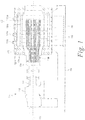
- FIG. 1 a longitudinal cross section of rotary pressure filter apparatus in accordance with one embodiment of the invention is shown generally at 100.
- the rotary pressure filter apparatus 100 operates under a positive pressure to filter and remove liquid from a solid-liquid mixture and to collect a solid product for further processing.
- the rotary pressure filter apparatus 100 includes a stationary housing 102 capable of withstanding an internal pressure above ambient.
- the housing 102 is mounted upon a frame 104.
- a rotary filter drum 106 Inside the housing 102 is a rotary filter drum 106.
- the rotary filter drum 106 rotates as indicated by arrow 108 around an axis 110 ( FIG 1 ) at speed of about 0.4 to 2 RPM, and in some embodiments at a speed of about 0.8 to 1.5 RPM.
- An axis 110 defines a longitudinal direction of the rotary drum 106 and the rotary pressure filter apparatus 100.
- the rotary filter drum 106 is driven by a drive mechanism 112, which is also mounted on the frame 104.
- a shaft 114 connects the drive mechanism 112 to a control head portion 116 of the rotary drum 106.
- the surface of the rotary drum 106 is spaced from the inside of the housing 102 such that a generally annular plenum 118 is formed therebetween.
- Material passageways 120a, 120b, 120c, 120d, and 120e are adapted to allow passage of material between the annular plenum 118 and a location outside the housing 102.
- One or more sealing members 122a, 122b, 122c, 122d, 122e are configured to contact the rotary drum 106 and divide the annular plenum 118 into a plurality of zones 124a, 124b, 124c, 124d, 124e.
- the sealing members 122 generally contact the rotary drum with enough pressure to pressure seal the zones 124 from each other but still allowing the rotary drum 106 to rotate.
- the sealing members 122 are each part of a sealing device 126 which includes an actuating mechanism adapted to members 122 in the radial direction to exert force against the rotary drum 106.
- the actuating mechanism is a pneumatic device including an inlet 128 for introducing gas into a plenum 130 to exert a pressure force against the outer surface of the respective sealing member 122.
- Suitable pressure forces exerted by the pneumatic device include those about 0.8 to 2.0 bar above the highest pressure in any of the zones 124a-124e of the rotary pressure filter apparatus 100.
- Those skilled in the art will recognize that other actuating mechanisms may be substituted for the pneumatic device.
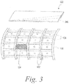
- a plurality of compartments 132 are arranged around the outer surface or circumference of the rotary filter drum 106 and rotate with the filter drum 106.
- the compartments 132 each include a filter member 134 (shown in one compartment in FIG.3 ) adjacent the filter drum.
- the filter member comprises a filter cloth supported over a metal screen in a filter housing (not shown).
- the filter cloth is manufactured from a polyether ether ketone (PEEK) polymer or a polyvinylidene difluoride (PVDF) polymer.
- PEEK polyether ether ketone
- PVDF polyvinylidene difluoride
- Each compartment 132 also has associated with it a corresponding outlet pipe 136 which also rotates with the filter drum 106 and the compartments 118.
- the outlet pipes 136 are configured such that filtrate received each compartment 118 passes through its corresponding filter member 134 adjacent the filter drum 106 and into its corresponding outlet pipe 136.
- the outlet pipes 136 remove the filtrate from the compartments 132 and deliver the filtrate to the control head 116, where it is collected through additional piping (not shown) and removed from the rotary pressure filter apparatus 100.
- the compartments 132 rotate with the rotary drum 106 and accordingly pass sequentially pass through each of the zones 124a, 124b, 124c, 124d, 124e.
- the compartments 132 are arranged in rows of four along the longitudinal direction 110. Those skilled in the art will recognize that other configurations of the compartments would be suitable as well.
- a pressurized feed containing a solid-liquid mixture is introduced into the feed inlet material passageway 120a and into plenum 118 in a first zone designated as feed zone 124a.
- the solid-liquid mixture is distributed into compartments 132.
- the pressure in the feed zone is maintained at about 3 bar(g) to about 7 bar(g), and in some embodiments, 5 bar(g) to 6 bar(g).
- liquid of the solid-liquid mixture is forced through the filter member 134 into outlet pipes 136. Filtrate thus exits the rotary pressure apparatus 100 through outlet pipes 136.
- the solid components of the solid-liquid mixture remain on the filter members 134 in the form of a filter cake.
- wash fluid is introduced into plenum 118 for distribution into the compartments 132 to wash the cake remaining on the filter members 134.
- wash fluid in introduced at a rate of about 0.5 kg to about 1.5 kg of wash fluid per 1 kg of filter cake.
- the wash fluid is removed by outlet 136.
- the rotary drum then continues to a second wash zone 124c, where additional wash fluid is introduced into zone 124c, designated as a second wash zone, and the cake on the filter members 134 is again washed.
- the wash fluid is selected to remove impurities from the filter cake while not interfering with further processing of the filter cake to recover the final solid product.
- the wash fluid comprises water.
- the wash fluid comprises condensate from another portion of an integrated process.
- the rotary drum 106 continues its rotation into drying zone, where a hot inert drying gas is introduced in the plenum 118 to dry the filter cake on the filter members 134.
- a hot inert drying gas is introduced in the plenum 118 to dry the filter cake on the filter members 134.
- the dried filter cake falls from the compartments 132 by gravity into a material passageway 120e designated as a product chute.
- a rinse solution may be injected through inlet 121 in order to clean the filter members of the compartments 132 before they continue into the next cycle through the zones.
- the rotary pressure filter apparatus 100 may include multiple filtering zones and multiple wash zones.
- the rotary pressure filter apparatus does not include a drying zone, for example, as disclosed in commonly assigned US Pat Application Serial No. 61/922,247 .
- the sealing members 122 in accordance with the present invention are designed to allow the compartments 132 to open more slowly as they enter a new zone. This is achieved by configuring the sealing members 122 to allow only a small portion, and then over time a progressively larger portion, of the compartments 132 to be exposed to the new zone as the compartments 132 rotate through the zones. Accordingly, the sealing members 122 are specifically designed to reduce pressure fluctuations as the compartments pass the sealing member into a new zone, which may each be held at different pressures. The pressure differentials between zones, for example, may be about 2 bar to 6 bar. Reduced pressure fluctuations allow fluid to enter the compartments 132 faster, thereby increasing the capacity of the rotary pressure filter apparatus 100. Furthermore, the filter members 134 have been shown to have less movement with reduced pressure fluctuations, thereby providing the potential for a longer lifespan of the filter member 134 as well.
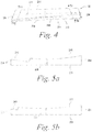
- a sealing member 122 in accordance with one embodiment of the present invention is shown in FIGS 4, 5A, 5B .
- the sealing member 122 has a unitary body 224, preferably made from a metal or polymer material, that extends along a length direction 226 and a width direction 228.
- the length direction is the same as the longitudinal direction 110 ( FIG 1 ) of the rotary drum 106, and the width direction is the same as the direction generally tangential to the rotary drum 106.
- a first side 230 ( FIG 5a and 5b ) of the sealing member 122 is generally planar.
- a second side 232 of the sealing member 122 is spaced from the first side and connected to the first side by edges 234, the volume between the first side and second side defining a thickness 236 of the sealing member in the radial direction of the rotary drum 106.
- the second side 232 is curved and concave relative to the first side 230, and is configured to fit flush against the surface of a cylindrical drum, such as the rotary drum 106 of the rotary pressure filter apparatus 100.
- the sealing member 122 includes a cutout portion 240 that varies in its width along at least one portion of its length.
- the cutout portion is tapered such that the width is narrower at one portion than at another portion of the longitudinal direction.
- the taper has a linear edge 242 and is a single taper extending substantially the entire longitudinal direction of the sealing member.
- the cutout portion 240 is variable in its width along its length direction only through a partial thickness 236 of the sealing member 122, allowing more strength for the sealing member 122 around the cutout portion 240.
- the cutout portion 240 allows the compartments 132 to open to the pressure in the upstream zone more gradually because as the compartments 132 passes the sealing member 122, the cutout portion 240 allow fluid communication with only a portion of the compartments, and that portion increases in size gradually over time as the rotary drum 106 continues to rotate. This gradual opening reduces pressure fluctuations of the material in the compartments 132.
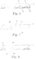
- FIG. 6 illustrates an alternative embodiment of the sealing member 122 in accordance with the present invention.
- the sealing member has multiple cutout portions 242 in a saw tooth configuration, each having a tapered edge 244 such that its width varies in its width along at least one portion of its length.
- FIG. 7 illustrates an alternative embodiment of the sealing member 122 in accordance with the present invention.
- the sealing member has a single cutout portions 250 having two opposing tapered edges with a generally centered apex 254 such that the cutout portion 250 varies in its width along at least one portion of its length.
- FIG. 8 illustrates an alternative embodiment of the sealing member 122 in accordance with the present invention.
- the sealing member 122 has multiple cutout portions 260, each cutout portion having curved edges 262 such that each cutout portion varies in its width along at least one portion of its length.
- each of the sealing members 122 may have a cutout portion 240. In other embodiments, only some of the sealing members have a cutout portion. For example, in the embodiment shown in FIG. 1 , only the sealing members 122b, 122c entering the wash zones 124b, 124c have cutout portions.
- the rotary pressure filter apparatus 100 may be used in a variety of separation processes. In some embodiments, the rotary pressure filter apparatus 100 is used to recover a solid product, or a liquid, or both, from a solid/liquid mixture. The solid is recovered from the apparatus as a filter cake that is formed on the filter members 134. The filtrate is recovered through outlet pipes 136. In one embodiment, the solid is a petrochemical, such as an aromatic carboxylic acid.
- the solid product is a crude terephthalic acid product and the liquid includes a solvent containing acetic acid.
- the crude terephthalic acid is recovered as a filter cake exiting the material passageway 120e.
- the solvent is recovered as filtrate exiting outlet pipes 136.
- the solid product is a purified terephthalic acid product and the liquid includes water.
- the purified terephthalic acid is recovered as a filter cake exiting the material passageway 120e.
- the water is recovered as filtrate exiting outlet pipes 136.
Landscapes
- Chemical & Material Sciences (AREA)
- Chemical Kinetics & Catalysis (AREA)
- Filtration Of Liquid (AREA)
- Centrifugal Separators (AREA)
- Organic Low-Molecular-Weight Compounds And Preparation Thereof (AREA)
Applications Claiming Priority (2)
| Application Number | Priority Date | Filing Date | Title |
|---|---|---|---|
| US201462029065P | 2014-07-25 | 2014-07-25 | |
| PCT/US2015/041793 WO2016014830A1 (en) | 2014-07-25 | 2015-07-23 | Rotary pressure filter apparatus with reduced pressure fluctuations |
Publications (2)
| Publication Number | Publication Date |
|---|---|
| EP3188817A1 EP3188817A1 (en) | 2017-07-12 |
| EP3188817B1 true EP3188817B1 (en) | 2021-04-28 |
Family
ID=53783992
Family Applications (1)
| Application Number | Title | Priority Date | Filing Date |
|---|---|---|---|
| EP15747689.6A Active EP3188817B1 (en) | 2014-07-25 | 2015-07-23 | Rotary pressure filter apparatus with reduced pressure fluctuations |
Country Status (10)
| Country | Link |
|---|---|
| US (1) | US10427073B2 (enExample) |
| EP (1) | EP3188817B1 (enExample) |
| JP (1) | JP6691102B2 (enExample) |
| KR (1) | KR102506343B1 (enExample) |
| CN (1) | CN106573188B (enExample) |
| BR (1) | BR112017001383A2 (enExample) |
| CA (1) | CA2954196A1 (enExample) |
| MX (1) | MX2017001043A (enExample) |
| RU (1) | RU2691046C2 (enExample) |
| WO (1) | WO2016014830A1 (enExample) |
Families Citing this family (20)
| Publication number | Priority date | Publication date | Assignee | Title |
|---|---|---|---|---|
| KR102396225B1 (ko) | 2013-12-31 | 2022-05-09 | 이네오스 유에스 케미컬즈 컴퍼니 | 무-건조 회전식 압력 필터를 이용한 고체-액체 분리 |
| KR20170040223A (ko) * | 2014-08-11 | 2017-04-12 | 비피 코포레이션 노쓰 아메리카 인코포레이티드 | 용량이 향상된 분리 프로세스 |
| GB201703029D0 (en) * | 2017-02-24 | 2017-04-12 | Invista Tech Sarl | Rotary pressure filter |
| CN108619776A (zh) * | 2017-03-22 | 2018-10-09 | 天华化工机械及自动化研究设计院有限公司 | 一种隔离单元及旋转压力过滤机 |
| TW201842956A (zh) | 2017-04-28 | 2018-12-16 | 美商Bp公司北美股份有限公司 | 使用加壓濕氣線路以避免於經純化的對苯二甲酸(pta)過濾器及線路的積垢 |
| CN107158780A (zh) * | 2017-06-20 | 2017-09-15 | 天华化工机械及自动化研究设计院有限公司 | 一种设有降低过滤机框架压力波动的装置及压力过滤机 |
| CN110944972A (zh) | 2017-06-29 | 2020-03-31 | Bp北美公司 | 制造芳族羧酸的方法 |
| EP3658526A4 (en) | 2017-07-25 | 2021-03-10 | BP Corporation North America Inc. | ROUTING OF A FILTER RINSING PRODUCT OF A PURIFIED AROMATIC CARBOXYLIC ACID FOR ENERGY OPTIMIZATION |
| EP3578242B8 (de) * | 2018-06-05 | 2021-09-08 | ANDRITZ Separation GmbH | Vakuum- und/oder druck-filtrationsvorrichtung zum filtern einer suspension |
| ES2893449T3 (es) * | 2018-06-05 | 2022-02-09 | ANDRITZ Separation GmbH | La invención se refiere a un tambor de filtro para un dispositivo de filtración a vacío y/o a presión |
| US12551825B2 (en) * | 2018-06-20 | 2026-02-17 | Andritz Inc. | Drum washer with gravity assist drainage |
| SE542326C2 (en) * | 2018-06-21 | 2020-04-14 | Valmet Oy | Vacuum filter |
| CN112334210A (zh) | 2018-06-29 | 2021-02-05 | Bp北美公司 | 使用大孔滤器的固-液分离方法 |
| EP3873640A1 (en) * | 2018-10-31 | 2021-09-08 | BHS-Sonthofen GmbH | Apparatus for reducing pressure fluctuation |
| WO2020102639A1 (en) | 2018-11-16 | 2020-05-22 | Bp Corporation North America Inc. | Process for manufacturing aromatic carboxylic acids |
| CN110183457A (zh) * | 2019-06-27 | 2019-08-30 | 浙江天顺药业有限公司 | 一种阿塞那平及其制备方法 |
| WO2021083522A1 (de) * | 2019-10-31 | 2021-05-06 | Bhs-Sonthofen Gmbh | Druckdrehfilter |
| CN114667276A (zh) | 2019-10-31 | 2022-06-24 | 英力士美国化学公司 | 固-液分离方法 |
| JP7540144B2 (ja) * | 2019-11-11 | 2024-08-27 | 中国電力株式会社 | ストレーナ |
| US20220355225A1 (en) * | 2021-05-10 | 2022-11-10 | Lyco Manufacturing Inc. | Externally Fed Screen for Filtration |
Citations (1)
| Publication number | Priority date | Publication date | Assignee | Title |
|---|---|---|---|---|
| FR1169569A (fr) * | 1955-09-12 | 1958-12-31 | Filtre-presse cylindrique à immersion travaillant en continu |
Family Cites Families (14)
| Publication number | Priority date | Publication date | Assignee | Title |
|---|---|---|---|---|
| US2741369A (en) * | 1953-05-22 | 1956-04-10 | Appbau G M B H Fa | Rotary filters |
| JPS51109306A (en) * | 1975-03-20 | 1976-09-28 | Toyo Pulp Co Ltd | Senisobutsushitsuo shorisurukaitenshikifuiruta |
| CN1030434C (zh) * | 1987-04-14 | 1995-12-06 | 化学工业部上海化工研究院 | 机械挤压式连续压滤机 |
| JP2595657B2 (ja) * | 1988-05-27 | 1997-04-02 | 三井石油化学工業株式会社 | スラリーから結晶を回収する方法 |
| JPH06327915A (ja) | 1993-05-24 | 1994-11-29 | Mitsui Petrochem Ind Ltd | スラリーから結晶を回収する方法及び装置 |
| US20050051473A1 (en) | 2001-06-12 | 2005-03-10 | Wolfgang Suss | Rotating filter system |
| US7374050B2 (en) * | 2004-04-23 | 2008-05-20 | Andritz Inc. | High capacity and high efficiency filter deck assembly |
| WO2005115957A1 (ja) * | 2004-05-28 | 2005-12-08 | Mitsubishi Chemical Corporation | 高純度テレフタル酸の製造方法 |
| DE102004033328A1 (de) * | 2004-07-09 | 2006-02-09 | Bhs-Sonthofen Gmbh | Filter mit Feststoff-Resuspendierung |
| FI126368B (fi) | 2008-05-06 | 2016-10-31 | Andritz Oy | Menetelmä ja järjestely rumpupesurin tiiviste-elementtien toiminnan parantamiseksi |
| CN201848141U (zh) * | 2010-05-18 | 2011-06-01 | 王光华 | 一种旋转压力过滤机 |
| CN202460268U (zh) * | 2011-06-29 | 2012-10-03 | 杭州化工机械有限公司 | 一种加压转鼓过滤机的区间密封结构 |
| JPWO2014049793A1 (ja) * | 2012-09-27 | 2016-08-22 | 三菱化工機株式会社 | 加圧式単室型回転濾過機の運転方法 |
| JP5282182B1 (ja) * | 2012-09-27 | 2013-09-04 | 三菱化工機株式会社 | 加圧式多室型回転濾過機及びその運転方法 |
-
2015
- 2015-07-23 WO PCT/US2015/041793 patent/WO2016014830A1/en not_active Ceased
- 2015-07-23 RU RU2017105410A patent/RU2691046C2/ru active
- 2015-07-23 CA CA2954196A patent/CA2954196A1/en not_active Abandoned
- 2015-07-23 US US15/322,320 patent/US10427073B2/en active Active
- 2015-07-23 CN CN201580038177.3A patent/CN106573188B/zh active Active
- 2015-07-23 JP JP2017504042A patent/JP6691102B2/ja active Active
- 2015-07-23 KR KR1020177004517A patent/KR102506343B1/ko active Active
- 2015-07-23 EP EP15747689.6A patent/EP3188817B1/en active Active
- 2015-07-23 MX MX2017001043A patent/MX2017001043A/es unknown
- 2015-07-23 BR BR112017001383A patent/BR112017001383A2/pt not_active Application Discontinuation
Patent Citations (1)
| Publication number | Priority date | Publication date | Assignee | Title |
|---|---|---|---|---|
| FR1169569A (fr) * | 1955-09-12 | 1958-12-31 | Filtre-presse cylindrique à immersion travaillant en continu |
Also Published As
| Publication number | Publication date |
|---|---|
| BR112017001383A2 (pt) | 2018-06-05 |
| RU2017105410A (ru) | 2018-08-27 |
| CA2954196A1 (en) | 2016-01-28 |
| RU2017105410A3 (enExample) | 2019-01-24 |
| JP6691102B2 (ja) | 2020-04-28 |
| WO2016014830A1 (en) | 2016-01-28 |
| EP3188817A1 (en) | 2017-07-12 |
| KR102506343B1 (ko) | 2023-03-03 |
| RU2691046C2 (ru) | 2019-06-07 |
| JP2017529226A (ja) | 2017-10-05 |
| MX2017001043A (es) | 2017-05-09 |
| CN106573188B (zh) | 2019-06-14 |
| CN106573188A (zh) | 2017-04-19 |
| US20180207558A1 (en) | 2018-07-26 |
| KR20170028444A (ko) | 2017-03-13 |
| US10427073B2 (en) | 2019-10-01 |
Similar Documents
| Publication | Publication Date | Title |
|---|---|---|
| EP3188817B1 (en) | Rotary pressure filter apparatus with reduced pressure fluctuations | |
| US10857490B2 (en) | Separation process having improved capacity | |
| EP3089804B1 (en) | Solid-liquid separations with a no-dry rotary pressure filter | |
| US8663482B2 (en) | Solid-liquid separating device, filtering apparatus, and solid-liquid separating method | |
| US1025059A (en) | Process of centrifugal separation. | |
| TW201603867A (zh) | 用於芳族羧酸的過濾機 | |
| US4346008A (en) | Rotary drum filter | |
| ITPI20080128A1 (it) | Metodo per la rimozione di prodotti di scarto durante un processo di estrazione purea da alimenti di origine vegetale, o animale e apparecchiatura che attua tale metodo | |
| US3575842A (en) | Recovering tar from tar sand | |
| US9024080B2 (en) | Process for isolating crystallized 2,2,4,4 tetramethyl-1,3-cyclobutanediol (TMCD) particles utilizing pressure filtration | |
| US4246108A (en) | Microstrainer apparatus and method | |
| CN104998770A (zh) | 一种能够灵活调整刮刀位置的离心机 | |
| JP4527307B2 (ja) | 集塵装置及びその運転制御方法 | |
| CN107847827B (zh) | 气体驱动式旋转过滤器 | |
| EP3524588A1 (en) | Cta solvent exchanging method | |
| CN100493666C (zh) | 高脱水型旋转加压脱水机 | |
| WO1990011833A1 (en) | Continuous filter centrifuge | |
| US1795179A (en) | Centrifugal drier | |
| CN101318895A (zh) | 一种分离提纯对苯二甲酸的新方法 | |
| CN109663732A (zh) | 一种中药材净选方法以及风选装置 |
Legal Events
| Date | Code | Title | Description |
|---|---|---|---|
| STAA | Information on the status of an ep patent application or granted ep patent |
Free format text: STATUS: THE INTERNATIONAL PUBLICATION HAS BEEN MADE |
|
| PUAI | Public reference made under article 153(3) epc to a published international application that has entered the european phase |
Free format text: ORIGINAL CODE: 0009012 |
|
| STAA | Information on the status of an ep patent application or granted ep patent |
Free format text: STATUS: REQUEST FOR EXAMINATION WAS MADE |
|
| 17P | Request for examination filed |
Effective date: 20170227 |
|
| AK | Designated contracting states |
Kind code of ref document: A1 Designated state(s): AL AT BE BG CH CY CZ DE DK EE ES FI FR GB GR HR HU IE IS IT LI LT LU LV MC MK MT NL NO PL PT RO RS SE SI SK SM TR |
|
| AX | Request for extension of the european patent |
Extension state: BA ME |
|
| DAV | Request for validation of the european patent (deleted) | ||
| DAX | Request for extension of the european patent (deleted) | ||
| STAA | Information on the status of an ep patent application or granted ep patent |
Free format text: STATUS: EXAMINATION IS IN PROGRESS |
|
| 17Q | First examination report despatched |
Effective date: 20180418 |
|
| GRAP | Despatch of communication of intention to grant a patent |
Free format text: ORIGINAL CODE: EPIDOSNIGR1 |
|
| STAA | Information on the status of an ep patent application or granted ep patent |
Free format text: STATUS: GRANT OF PATENT IS INTENDED |
|
| INTG | Intention to grant announced |
Effective date: 20200508 |
|
| GRAJ | Information related to disapproval of communication of intention to grant by the applicant or resumption of examination proceedings by the epo deleted |
Free format text: ORIGINAL CODE: EPIDOSDIGR1 |
|
| STAA | Information on the status of an ep patent application or granted ep patent |
Free format text: STATUS: EXAMINATION IS IN PROGRESS |
|
| INTC | Intention to grant announced (deleted) | ||
| GRAP | Despatch of communication of intention to grant a patent |
Free format text: ORIGINAL CODE: EPIDOSNIGR1 |
|
| STAA | Information on the status of an ep patent application or granted ep patent |
Free format text: STATUS: GRANT OF PATENT IS INTENDED |
|
| INTG | Intention to grant announced |
Effective date: 20201105 |
|
| GRAS | Grant fee paid |
Free format text: ORIGINAL CODE: EPIDOSNIGR3 |
|
| GRAA | (expected) grant |
Free format text: ORIGINAL CODE: 0009210 |
|
| STAA | Information on the status of an ep patent application or granted ep patent |
Free format text: STATUS: THE PATENT HAS BEEN GRANTED |
|
| AK | Designated contracting states |
Kind code of ref document: B1 Designated state(s): AL AT BE BG CH CY CZ DE DK EE ES FI FR GB GR HR HU IE IS IT LI LT LU LV MC MK MT NL NO PL PT RO RS SE SI SK SM TR |
|
| RAP1 | Party data changed (applicant data changed or rights of an application transferred) |
Owner name: INEOS US CHEMICALS COMPANY Owner name: BHS-SONTHOFEN GMBH |
|
| REG | Reference to a national code |
Ref country code: GB Ref legal event code: FG4D |
|
| REG | Reference to a national code |
Ref country code: CH Ref legal event code: EP |
|
| REG | Reference to a national code |
Ref country code: AT Ref legal event code: REF Ref document number: 1386465 Country of ref document: AT Kind code of ref document: T Effective date: 20210515 |
|
| REG | Reference to a national code |
Ref country code: DE Ref legal event code: R096 Ref document number: 602015068653 Country of ref document: DE |
|
| REG | Reference to a national code |
Ref country code: IE Ref legal event code: FG4D |
|
| REG | Reference to a national code |
Ref country code: LT Ref legal event code: MG9D |
|
| REG | Reference to a national code |
Ref country code: AT Ref legal event code: MK05 Ref document number: 1386465 Country of ref document: AT Kind code of ref document: T Effective date: 20210428 |
|
| PG25 | Lapsed in a contracting state [announced via postgrant information from national office to epo] |
Ref country code: LT Free format text: LAPSE BECAUSE OF FAILURE TO SUBMIT A TRANSLATION OF THE DESCRIPTION OR TO PAY THE FEE WITHIN THE PRESCRIBED TIME-LIMIT Effective date: 20210428 Ref country code: NL Free format text: LAPSE BECAUSE OF FAILURE TO SUBMIT A TRANSLATION OF THE DESCRIPTION OR TO PAY THE FEE WITHIN THE PRESCRIBED TIME-LIMIT Effective date: 20210428 Ref country code: FI Free format text: LAPSE BECAUSE OF FAILURE TO SUBMIT A TRANSLATION OF THE DESCRIPTION OR TO PAY THE FEE WITHIN THE PRESCRIBED TIME-LIMIT Effective date: 20210428 Ref country code: BG Free format text: LAPSE BECAUSE OF FAILURE TO SUBMIT A TRANSLATION OF THE DESCRIPTION OR TO PAY THE FEE WITHIN THE PRESCRIBED TIME-LIMIT Effective date: 20210728 Ref country code: AT Free format text: LAPSE BECAUSE OF FAILURE TO SUBMIT A TRANSLATION OF THE DESCRIPTION OR TO PAY THE FEE WITHIN THE PRESCRIBED TIME-LIMIT Effective date: 20210428 Ref country code: HR Free format text: LAPSE BECAUSE OF FAILURE TO SUBMIT A TRANSLATION OF THE DESCRIPTION OR TO PAY THE FEE WITHIN THE PRESCRIBED TIME-LIMIT Effective date: 20210428 |
|
| PG25 | Lapsed in a contracting state [announced via postgrant information from national office to epo] |
Ref country code: NO Free format text: LAPSE BECAUSE OF FAILURE TO SUBMIT A TRANSLATION OF THE DESCRIPTION OR TO PAY THE FEE WITHIN THE PRESCRIBED TIME-LIMIT Effective date: 20210728 Ref country code: PL Free format text: LAPSE BECAUSE OF FAILURE TO SUBMIT A TRANSLATION OF THE DESCRIPTION OR TO PAY THE FEE WITHIN THE PRESCRIBED TIME-LIMIT Effective date: 20210428 Ref country code: PT Free format text: LAPSE BECAUSE OF FAILURE TO SUBMIT A TRANSLATION OF THE DESCRIPTION OR TO PAY THE FEE WITHIN THE PRESCRIBED TIME-LIMIT Effective date: 20210830 Ref country code: RS Free format text: LAPSE BECAUSE OF FAILURE TO SUBMIT A TRANSLATION OF THE DESCRIPTION OR TO PAY THE FEE WITHIN THE PRESCRIBED TIME-LIMIT Effective date: 20210428 Ref country code: SE Free format text: LAPSE BECAUSE OF FAILURE TO SUBMIT A TRANSLATION OF THE DESCRIPTION OR TO PAY THE FEE WITHIN THE PRESCRIBED TIME-LIMIT Effective date: 20210428 Ref country code: LV Free format text: LAPSE BECAUSE OF FAILURE TO SUBMIT A TRANSLATION OF THE DESCRIPTION OR TO PAY THE FEE WITHIN THE PRESCRIBED TIME-LIMIT Effective date: 20210428 Ref country code: IS Free format text: LAPSE BECAUSE OF FAILURE TO SUBMIT A TRANSLATION OF THE DESCRIPTION OR TO PAY THE FEE WITHIN THE PRESCRIBED TIME-LIMIT Effective date: 20210828 Ref country code: GR Free format text: LAPSE BECAUSE OF FAILURE TO SUBMIT A TRANSLATION OF THE DESCRIPTION OR TO PAY THE FEE WITHIN THE PRESCRIBED TIME-LIMIT Effective date: 20210729 |
|
| REG | Reference to a national code |
Ref country code: NL Ref legal event code: MP Effective date: 20210428 |
|
| PG25 | Lapsed in a contracting state [announced via postgrant information from national office to epo] |
Ref country code: RO Free format text: LAPSE BECAUSE OF FAILURE TO SUBMIT A TRANSLATION OF THE DESCRIPTION OR TO PAY THE FEE WITHIN THE PRESCRIBED TIME-LIMIT Effective date: 20210428 Ref country code: ES Free format text: LAPSE BECAUSE OF FAILURE TO SUBMIT A TRANSLATION OF THE DESCRIPTION OR TO PAY THE FEE WITHIN THE PRESCRIBED TIME-LIMIT Effective date: 20210428 Ref country code: SM Free format text: LAPSE BECAUSE OF FAILURE TO SUBMIT A TRANSLATION OF THE DESCRIPTION OR TO PAY THE FEE WITHIN THE PRESCRIBED TIME-LIMIT Effective date: 20210428 Ref country code: SK Free format text: LAPSE BECAUSE OF FAILURE TO SUBMIT A TRANSLATION OF THE DESCRIPTION OR TO PAY THE FEE WITHIN THE PRESCRIBED TIME-LIMIT Effective date: 20210428 Ref country code: CZ Free format text: LAPSE BECAUSE OF FAILURE TO SUBMIT A TRANSLATION OF THE DESCRIPTION OR TO PAY THE FEE WITHIN THE PRESCRIBED TIME-LIMIT Effective date: 20210428 Ref country code: EE Free format text: LAPSE BECAUSE OF FAILURE TO SUBMIT A TRANSLATION OF THE DESCRIPTION OR TO PAY THE FEE WITHIN THE PRESCRIBED TIME-LIMIT Effective date: 20210428 Ref country code: DK Free format text: LAPSE BECAUSE OF FAILURE TO SUBMIT A TRANSLATION OF THE DESCRIPTION OR TO PAY THE FEE WITHIN THE PRESCRIBED TIME-LIMIT Effective date: 20210428 |
|
| REG | Reference to a national code |
Ref country code: DE Ref legal event code: R097 Ref document number: 602015068653 Country of ref document: DE |
|
| REG | Reference to a national code |
Ref country code: DE Ref legal event code: R119 Ref document number: 602015068653 Country of ref document: DE |
|
| REG | Reference to a national code |
Ref country code: CH Ref legal event code: PL |
|
| PLBE | No opposition filed within time limit |
Free format text: ORIGINAL CODE: 0009261 |
|
| STAA | Information on the status of an ep patent application or granted ep patent |
Free format text: STATUS: NO OPPOSITION FILED WITHIN TIME LIMIT |
|
| GBPC | Gb: european patent ceased through non-payment of renewal fee |
Effective date: 20210728 |
|
| PG25 | Lapsed in a contracting state [announced via postgrant information from national office to epo] |
Ref country code: MC Free format text: LAPSE BECAUSE OF FAILURE TO SUBMIT A TRANSLATION OF THE DESCRIPTION OR TO PAY THE FEE WITHIN THE PRESCRIBED TIME-LIMIT Effective date: 20210428 |
|
| 26N | No opposition filed |
Effective date: 20220131 |
|
| PG25 | Lapsed in a contracting state [announced via postgrant information from national office to epo] |
Ref country code: LI Free format text: LAPSE BECAUSE OF NON-PAYMENT OF DUE FEES Effective date: 20210731 Ref country code: GB Free format text: LAPSE BECAUSE OF NON-PAYMENT OF DUE FEES Effective date: 20210728 Ref country code: DE Free format text: LAPSE BECAUSE OF NON-PAYMENT OF DUE FEES Effective date: 20220201 Ref country code: CH Free format text: LAPSE BECAUSE OF NON-PAYMENT OF DUE FEES Effective date: 20210731 |
|
| PG25 | Lapsed in a contracting state [announced via postgrant information from national office to epo] |
Ref country code: IS Free format text: LAPSE BECAUSE OF FAILURE TO SUBMIT A TRANSLATION OF THE DESCRIPTION OR TO PAY THE FEE WITHIN THE PRESCRIBED TIME-LIMIT Effective date: 20210828 Ref country code: LU Free format text: LAPSE BECAUSE OF NON-PAYMENT OF DUE FEES Effective date: 20210723 Ref country code: FR Free format text: LAPSE BECAUSE OF NON-PAYMENT OF DUE FEES Effective date: 20210731 Ref country code: AL Free format text: LAPSE BECAUSE OF FAILURE TO SUBMIT A TRANSLATION OF THE DESCRIPTION OR TO PAY THE FEE WITHIN THE PRESCRIBED TIME-LIMIT Effective date: 20210428 |
|
| PG25 | Lapsed in a contracting state [announced via postgrant information from national office to epo] |
Ref country code: IT Free format text: LAPSE BECAUSE OF FAILURE TO SUBMIT A TRANSLATION OF THE DESCRIPTION OR TO PAY THE FEE WITHIN THE PRESCRIBED TIME-LIMIT Effective date: 20210428 Ref country code: IE Free format text: LAPSE BECAUSE OF NON-PAYMENT OF DUE FEES Effective date: 20210723 |
|
| PG25 | Lapsed in a contracting state [announced via postgrant information from national office to epo] |
Ref country code: HU Free format text: LAPSE BECAUSE OF FAILURE TO SUBMIT A TRANSLATION OF THE DESCRIPTION OR TO PAY THE FEE WITHIN THE PRESCRIBED TIME-LIMIT; INVALID AB INITIO Effective date: 20150723 |
|
| P01 | Opt-out of the competence of the unified patent court (upc) registered |
Effective date: 20230523 |
|
| PG25 | Lapsed in a contracting state [announced via postgrant information from national office to epo] |
Ref country code: CY Free format text: LAPSE BECAUSE OF FAILURE TO SUBMIT A TRANSLATION OF THE DESCRIPTION OR TO PAY THE FEE WITHIN THE PRESCRIBED TIME-LIMIT Effective date: 20210428 |
|
| PG25 | Lapsed in a contracting state [announced via postgrant information from national office to epo] |
Ref country code: MK Free format text: LAPSE BECAUSE OF FAILURE TO SUBMIT A TRANSLATION OF THE DESCRIPTION OR TO PAY THE FEE WITHIN THE PRESCRIBED TIME-LIMIT Effective date: 20210428 |
|
| PG25 | Lapsed in a contracting state [announced via postgrant information from national office to epo] |
Ref country code: MT Free format text: LAPSE BECAUSE OF FAILURE TO SUBMIT A TRANSLATION OF THE DESCRIPTION OR TO PAY THE FEE WITHIN THE PRESCRIBED TIME-LIMIT Effective date: 20210428 |
|
| PGFP | Annual fee paid to national office [announced via postgrant information from national office to epo] |
Ref country code: TR Payment date: 20250711 Year of fee payment: 11 |
|
| PGFP | Annual fee paid to national office [announced via postgrant information from national office to epo] |
Ref country code: BE Payment date: 20250728 Year of fee payment: 11 |