EP3188359B1 - Vorrichtung und steuerungsverfahren zur ansteuerung eines sensorlosen bldc-motors - Google Patents
Vorrichtung und steuerungsverfahren zur ansteuerung eines sensorlosen bldc-motors Download PDFInfo
- Publication number
- EP3188359B1 EP3188359B1 EP16192412.1A EP16192412A EP3188359B1 EP 3188359 B1 EP3188359 B1 EP 3188359B1 EP 16192412 A EP16192412 A EP 16192412A EP 3188359 B1 EP3188359 B1 EP 3188359B1
- Authority
- EP
- European Patent Office
- Prior art keywords
- phase
- voltage
- motor
- switches
- zcp
- Prior art date
- Legal status (The legal status is an assumption and is not a legal conclusion. Google has not performed a legal analysis and makes no representation as to the accuracy of the status listed.)
- Not-in-force
Links
Images



Classifications
-
- H—ELECTRICITY
- H02—GENERATION; CONVERSION OR DISTRIBUTION OF ELECTRIC POWER
- H02P—CONTROL OR REGULATION OF ELECTRIC MOTORS, ELECTRIC GENERATORS OR DYNAMO-ELECTRIC CONVERTERS; CONTROLLING TRANSFORMERS, REACTORS OR CHOKE COILS
- H02P6/00—Arrangements for controlling synchronous motors or other dynamo-electric motors using electronic commutation dependent on the rotor position; Electronic commutators therefor
- H02P6/14—Electronic commutators
- H02P6/16—Circuit arrangements for detecting position
- H02P6/18—Circuit arrangements for detecting position without separate position detecting elements
- H02P6/182—Circuit arrangements for detecting position without separate position detecting elements using back-emf in windings
-
- H—ELECTRICITY
- H02—GENERATION; CONVERSION OR DISTRIBUTION OF ELECTRIC POWER
- H02P—CONTROL OR REGULATION OF ELECTRIC MOTORS, ELECTRIC GENERATORS OR DYNAMO-ELECTRIC CONVERTERS; CONTROLLING TRANSFORMERS, REACTORS OR CHOKE COILS
- H02P27/00—Arrangements or methods for the control of AC motors characterised by the kind of supply voltage
- H02P27/04—Arrangements or methods for the control of AC motors characterised by the kind of supply voltage using variable-frequency supply voltage, e.g. inverter or converter supply voltage
- H02P27/06—Arrangements or methods for the control of AC motors characterised by the kind of supply voltage using variable-frequency supply voltage, e.g. inverter or converter supply voltage using DC to AC converters or inverters
- H02P27/08—Arrangements or methods for the control of AC motors characterised by the kind of supply voltage using variable-frequency supply voltage, e.g. inverter or converter supply voltage using DC to AC converters or inverters with pulse width modulation
-
- H—ELECTRICITY
- H02—GENERATION; CONVERSION OR DISTRIBUTION OF ELECTRIC POWER
- H02P—CONTROL OR REGULATION OF ELECTRIC MOTORS, ELECTRIC GENERATORS OR DYNAMO-ELECTRIC CONVERTERS; CONTROLLING TRANSFORMERS, REACTORS OR CHOKE COILS
- H02P6/00—Arrangements for controlling synchronous motors or other dynamo-electric motors using electronic commutation dependent on the rotor position; Electronic commutators therefor
- H02P6/14—Electronic commutators
- H02P6/15—Controlling commutation time
- H02P6/157—Controlling commutation time wherein the commutation is function of electro-magnetic force [EMF]
-
- H—ELECTRICITY
- H02—GENERATION; CONVERSION OR DISTRIBUTION OF ELECTRIC POWER
- H02P—CONTROL OR REGULATION OF ELECTRIC MOTORS, ELECTRIC GENERATORS OR DYNAMO-ELECTRIC CONVERTERS; CONTROLLING TRANSFORMERS, REACTORS OR CHOKE COILS
- H02P6/00—Arrangements for controlling synchronous motors or other dynamo-electric motors using electronic commutation dependent on the rotor position; Electronic commutators therefor
- H02P6/14—Electronic commutators
- H02P6/16—Circuit arrangements for detecting position
- H02P6/18—Circuit arrangements for detecting position without separate position detecting elements
- H02P6/187—Circuit arrangements for detecting position without separate position detecting elements using the star point voltage
Definitions
- the present invention relates to a device and a control method for driving a sensorless BLDC motor, particularly related to a technology configured to increase the accuracy of detection of Zero Cross Point through a non-commutation period in a PWM control.
- BLDC Motor Brushless DC Motor
- BLDC Motor stator an armature formed by applying a current to the coil
- a permanent magnet formed by repeated N and S poles and is used as a rotor.
- commutation represents changing the current direction of the motor stator coil to allow the rotor to be rotated.
- a device configured to detect the position of the rotor is required.
- a position detection sensor such as a Hall sensor, a resolver element and an encoder may be used.
- a sensorless method which can drive a motor without a sensor for the detection of the position of the rotor is used.
- the method for driving a sensorless BLDC motor includes extracting a back electromotive force (EMF) generated in stator coil of each phase while the motor is rotated, and estimating position information of the rotor and each phase current commutation time by using a zero cross point of the phase back EMF.
- EMF back electromotive force
- US 20040263104 A1 relates to a device and a method for driving a sensorless motor, and, in particular, those for controlling the start of a sensorless motor under a forced commutation control.
- US 20060170383 A1 relates to relates to a motor drive apparatus, and particularly to a motor drive apparatus driving a 3-phase brushless motor without using a Hall sensor.
- US 20100181953A1 relates to a controller for a 3-phase brushless DC motor, and in particular to a controller for detecting a position of a rotor in a 3-phase brushless DC motor by sensor-less detection, in order to perform a commutation operation of the motor.
- the present invention provides a device and a control method for driving a sensorless BLDC motor according to the independent claims 1 and 7, respectively, that can increase the accuracy of detection of Zero Cross Point through a non-commutation period in the PWM control to precisely estimate position information of a rotor. Further embodiments of the present invention are defined in the dependent claims 2 - 6 and 8 - 10.
- the terms “include” and “comprise” mean inclusion without limitation; the term “or,” is inclusive, meaning and/or; the phrases “associated with” and “associated therewith” may mean to include, be included within, interconnect with, contain, be contained within, connect to or with, couple to or with, be communicable with, cooperate with, interleave, juxtapose, be proximate to, be bound to or with, have, have a property of, or the like; and the term “controller” means any device, system or part thereof that controls at least one operation, such a device may be implemented in hardware, firmware or software, or some combination of at least two of the same. It should be noted that the functionality associated with any particular controller may be centralized or distributed, whether locally or remotely.
- switching element represents a wiring element configured to connect or disconnect the current in an electrical and electronic device.
- the switching element may include a transistor configured to connect the current according to a control signal, a bipolar junction transistor (BJT), and a field effect transistor (FET), but is not limited thereto.
- BJT bipolar junction transistor
- FET field effect transistor
- the switching element When the switching element acts as a FET, the switching element may include a gate terminal, a drain terminal, and a source terminal.
- the drain terminal may act as the source terminal
- the source terminal may act as the drain terminal.
- the switching element may be divided into a low-voltage switching element (LN) operated in a low-voltage and a high-voltage switching element (HN) operated in a high-voltage.
- the high-voltage switching element (HN) may be configured to withstand a state in which a high-voltage is applied to the drain terminal, and may be typically used in a variety of power elements.
- the high-voltage switching element may include a Double-diffused MOSFET (DMOSFET), an Insulated Gate Bipolar Transistor (IGBT), an Extended Drain MOSFET (EDMOSFET), a Lateral Double-diffused MOSFET (LDMOSFET), and a gallium nitride (GaN) transistor, but is not limited thereto.
- DMOSFET Double-diffused MOSFET
- IGBT Insulated Gate Bipolar Transistor
- EDMOSFET Extended Drain MOSFET
- LDMOSFET Lateral Double-diffused MOSFET
- GaN gallium nitride
- turn-on represents changing a state of switching element from non-conducting state to conducting state (commutation state).
- turn-on represents supplying a signal to a gate to allow a current to flow to the switching element.
- turn-off' represents changing a state of switching element from conducting state to non-conducting state (non-commutation state).
- a method for driving a sensorless BLDC motor may include extracting a back electromotive force (EMF) generated in a stator coil of each phase while the motor is rotated, and estimating position information of the rotor and each phase current commutation time by using a Zero Crossing Point (ZCP) of the phase back EMF.
- the ZCP represents a cross point of a period in which a back EMF of each phase is passed at a zero point, and the control of driving motor may be allowed by detecting a position of the rotor without an additional position detection sensor, e.g., a hall sensor, through detecting the ZCP.
- the method may include measuring a phase voltage directly by using a neutral point that is not considered in manufacturing the motor.
- the ZCP of the phase back EMF voltage may be extracted by comparing a terminal voltage with a half of a driving voltage of the motor. Therefore, the method for driving motor by using the aforementioned methods may be not applied in a low-speed driving area, in which a back EMF is small, and may have a difficulty in that a terminal voltage of a motor driven by a pulse width modulation method includes a noise component caused by a high-speed switching.
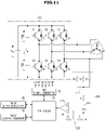
- FIG. 1 is a view illustrating a connection between an inverter for driving a general BLDC motor and a motor
- FIG. 2 is a view illustrating a three phase back electromotive force and a hall sensor for driving a BLDC motor
- FIG. 3 is a view illustrating a current flow based on a switch control.
- a three phase inverter 100 to control a three BLDC motor may be illustrated in FIG. 1 and the three phase inverter 100 may be a driving circuit configured to perform 150 degree commutation control by using six Metal Oxide Silicon Field Effect Transistors (MOSFETs) to control voltage duty.
- MOSFETs Metal Oxide Silicon Field Effect Transistors
- the control may be performed by a 120 degree commutation method, and the 150 degree commutation method may prevent an arm short caused by crossing operation of the switch in a mechanical manner (30 degrees) and may not need a dead time to prevent the arm short.
- a gate signal of 6 switches Q1 to Q6 included in the three phase inverter 100 may be a square wave form.
- a controller 70 may drive a switch by using a gate signal that is pulse width modulated (PWM) or pulse frequency modulated (PFM) by controlling a PWM signal generator 80.
- PWM pulse width modulated
- PFM pulse frequency modulated
- Pulse width modulation is one method of transmitting an analog signal after modulating into a digital signal having strength in the noise, because an analog is damaged due to the noise. That is, since the PWM is a method of modulating a pulse width as much as modulating an analog signal into a digital value, when a signal width is large, a pulse width may become large, and when a signal width is small, a pulse width may become small.
- the pulse frequency modulation is a modulation method of changing pulse repetition frequency according to the size of signal, and when a signal is large, the repetition frequency may become large, and when a signal is small, the repetition frequency may become small.
- a control method of switch operation may correspond to a well-known method.
- the switch Q to Q6 may be implemented by a gallium nitride (GaN) field-effect transistor (FET).
- GaN gallium nitride
- Si-MOSFET Silicon MOSFET
- the GaN FET known as a next-generation power semiconductor element may have a relative low conduction resistance, due to features of a wide band gap semiconductor compared with the Si MOSFET, so that the generation of heat may be minimized.
- the GaN FET may have a small capacitance value and may perform a high-speed switching due to short switching turn-on and turn-off time. A loss generated during switching may be less than Si-MOSFET. Accordingly, by using a switch implemented by the GaN FET, the high-efficiency of power factor correction circuit may be realized.
- the volume of passive element may be reduced and the high-density of circuit may be realized.
- the performance of the power factor correction circuit may be maximized.
- a switch Q1 and Q4 may be illustrated by 'A'
- a switch Q2 and Q5 may be illustrated by 'B'
- a switch Q3 and Q6 may be illustrated by 'C '.
- A, B, and C are randomly set to describe a switching based on the three phase back EMF or a hall sensor signal.
- the switch Q1 and Q4 may be not turned on or off at the same time, and when either the switch Q1 or Q4 is turned on, the other may be turned off.
- the switch Q2 and Q5 may not be turned on or off at the same time, and the switch Q3 and Q6 may not be turned on or off at the same time.
- each phase voltage of BLDC motor may be estimated as following Equation 1, and each phase voltage may include a component of phase current, a back EMF and a neutral point.
- V a V b V c R i a i b i c + L d dt i a i b i c + e a e b e c + V n V n V n
- Va, Vb, and Vc are a phase voltage
- ia, ib, and ic are a phase current
- ea, eb, and ec are a phase back EMF
- Vn is a neutral point voltage
- FIG. 2 illustrates the three phase back EMF and a hall sensor signal by a 150° commutation method.
- a method by using a hall sensor may be a conventional method for detection of the position of the rotor, and may be configured to control a switching for driving a motor based on a signal Ha, Hb, and Hc detected by the hall sensor.
- a method for driving a sensorless BLDC motor may include extracting back EMF ea, eb, and ec from the stator coil of each phase while the motor is rotated, and estimating the position information of the rotor and commutation time of each phase current based on the extraction.
- a three phase DC motor may be represented by a Phase U, a Phase V, and a Phase W.
- Q1 is turned on in the switch A of FIG. 1 , between 135° and 285°, Q2 is turned on in the switch B of FIG. 1 , and greater than 255°, Q3 is turned on in the switch C of FIG. 1 .
- A+ may represent that Q1 is turned on, and A- may represent that Q4 is turned on.
- B+ may represent that Q2 is turned on, and B- may represent Q5 is turned on.
- C+ may represent that Q3 is turned on, and C- may represent Q6 is turned on.
- the switch table may be made based on a signal detected by a hall sensor or a back EMF generated in the stator coil of each phase while the motor is rotated, and based on the switch table, the current flow applied from the three phase inverter 100 of FIG. 1 to the three phase DC motor is illustrated in FIG. 3 .
- the switch table of FIG. 2 when an electrical angle is between 135° ⁇ 165°, the switch table may be illustrated by A+, B+, and C-. That is, in this period, Q1, Q2 and Q6 may be turned on and the current flow applied from the three phase inverter 100 of FIG. 1 to the three phase direct current motor is illustrated in FIG. 3 so that the driving of the three phase DC motor may be controlled.
- FIG. 4 is a control block diagram illustrating a device for driving a sensorless BLDC motor in accordance with an embodiment of the present invention.
- a device for driving a sensorless BLDC motor in accordance with an embodiment may include a terminal voltage detector 50, a zero cross point detector 60, a PWM signal generator 80, a pulse width modulator 85, and a phase current converter 90.
- the terminal voltage detector 50 may detect a three phase terminal voltage from an output terminal of the three phase inverter 100. That is, the three phase inverter 100 may convert DC input voltage supplied from the outside into a three phase AC voltage of pulse shape that is associated with driving the BLDC motor, and output the three phase AC voltage. The terminal voltage detector 50 may detect a voltage between terminals by calculating a voltage difference between the three phase output terminals of the three phase inverter 100, and input the voltage between terminals to the controller 70.
- the voltage between terminals detected by the terminal voltage detector 50 may be calculated by a difference between each phase voltage of the BLDC motor, as illustrated in Equation 1. As mentioned above, each phase voltage may include a back EMF component, and the voltage between terminals detected by the terminal voltage detector 50 may include a back EMF of each phase of the three phase motor.
- the ZCP detector 60 may extract a ZCP of three phase back EMF by comparing voltages between terminals detected by the terminal voltage detector 50 with a zero point of input voltage of the motor. That is, the terminal voltage detector 50 may detect a voltage between terminals including the three phase back EMF by receiving a voltage of each terminal from the BLDC motor, and transmit the detected voltage between terminals to a Zero Point (ZP) comparator 61 included in the ZCP detector 60.
- ZP Zero Point
- the ZP comparator 61 may compare the three phase terminal voltage transmitted from the terminal voltage detector 50 with the input voltage of the motor, and then may output a positive voltage in a period in which a difference between the three phase terminal voltage and the input voltage of the motor is positive, and may output a Zero voltage in an period in which a difference between the three phase terminal voltage and the input voltage of the motor is negative.
- the controller 70 may perform a PWM control of the terminal voltage based on the three phase back EMF included in the terminal voltage detected by the terminal voltage detector 50.
- the PWM control is a method of transmitting an analog signal after modulating into a digital signal having strength in the noise, because an analog is damaged due to the noise, when transmitting an analog signal in a wired or wireless method. That is, the controller 70 may modulate an analog signal of three phase back EMF included in the terminal voltage into a digital signal.
- the PWM control performed by the controller 70 includes a non-commutation control, described later, and the non-commutation control represents a control through generation of a non-commutation signal period in which a PWM signal is removed to prevent the switching of the current from occurring in the three phase inverter 100.
- the ZCP detector 60 detects a ZCP of the three phase back EMF based on a PWM signal generated from the PWM control including a non-commutation control of the three phase terminal voltage performed by the controller 70.
- the controller 70 may acquire the position information of the rotor based on the ZCP detected by the ZCP detector 60, and may transmit a control signal configured to control a PWM signal pattern supplied to the three phase inverter 100 to prevent over-current from being supplied to the motor by controlling a timing in which a voltage is applied to the stator winding. By transmitting a control signal, a switching operation of the three phase inverter 100 may be controlled. That is, the controller 70 may perform a control algorithm of the overall three phase inverter 100
- the PWM signal generator 80 may determine a switching pattern of a PWM signal based on a PWM signal outputted by the controller 70 and transmit the determined switching pattern to the three phase inverter 100, so as to allow the switches Q1 to Q6 to be operated according to the switch pattern.
- the pulse width modulator 85 may change a pulse width of a PWM signal outputted from the PWM signal generator 80 so as to change a rotation speed of the motor.
- the pulse width modulator 85 may adjust the switching of the three phase inverter 100 to vary the rotation speed of the motor so as to control a sensorless driving of the BLDC motor.
- the phase current converter 90 may determine a position of the rotor of the three phase motor through a ZCP of the three phase back EMF extracted by the ZCP detector 60, and determine a commutation time based on the determination so as to control the three phase inverter 100 to be operated.
- FIG. 5 is a control flow illustrating a terminal voltage detector and a zero point comparator and FIGS. 6 and 7 are views illustrating a detailed configuration of a terminal voltage detector in accordance with an embodiment of the present invention.
- the terminal voltage detector 50 may detect a voltage between terminals including a back EMF between phases by receiving each terminal voltage from the BLDC motor by using a differential amplifier, and may transmit the voltage between terminals to the ZP comparator 61.
- the ZP comparator 61 may compare the voltage between terminals, which is received from the terminal voltage detector 50, with an input voltage of the motor through the comparator so that a square wave signal, which is configured to output a positive voltage in a period where a difference between a terminal voltage and the input voltage of the motor is positive, and configured to output a negative voltage in a period where a difference between a terminal voltage and the input voltage of the motor is negative.
- Va, Vb, and Vc are a phase voltage
- Vac, Vba, and Vcb are a voltage between terminals between phases
- Sac, Sba, and Scb are a signal transmitted by comparing a three phase terminal voltage with an input voltage of the motor.
- terminal voltages Va, Vb, and Vc of three phases (U, V, W) of a DC motor may be divided by a resistance R1 and R2 and then inputted to a A/D input port 72 of the controller 70.
- An additional zener diode may be included in the A/D input port 72 so that a voltage value, which is divided by each resistance distribution circuit R1 and R2, is limited within a range of the A/D input voltage of each phase terminal voltage.
- a sensorless operation period of BLDC motor a result of comparing a terminal voltage of each phase (U, V, W) with a half of a voltage of the DC terminal of the three phase inverter 100 may be input to a digital input port 74 of the controller 70 so as to detect a ZCP of the three phase back EMF included in the three phase terminal voltage.
- FIG. 8 is a view illustrating a signal in which a non-commutation period is generated from a PWM signal in accordance with an embodiment of the present invention
- FIG. 9 is a view illustrating a switch operation to generate a non-commutation signal period in accordance with an embodiment of the present invention.
- the PWM control may be performed on the three phase back EMF included in the terminal voltage, and a ZCP of the three phase back EMF may be extracted from the PWM control so that a switch of the three phase inverter 100 may be controlled.
- the controller 70 may perform a non-commutation control on the PWM signal based on the three phase back EMF so that the difficulties caused by the switching noise may be relieved and the accurate ZCP may be detected, thereby detecting a position of the rotor precisely.
- a device for driving a sensorless BLDC motor in accordance with an embodiment of the present invention, there is not an additional position detection sensor, e.g., a hall sensor, to detect a position of a rotor, and thus the rotor may be arranged according to a predetermined phase prior to driving the motor.
- an additional position detection sensor e.g., a hall sensor
- the controller 70 performs a three phase non-commutation control on the PWM signal to generate a non-commutation signal period in each phase.
- the controller 70 detects a three phase back EMF based on the three phase terminal voltage detected by the terminal voltage detector 50 and generates a PWM signal on the three phase back EMF.
- the controller 70 performs the non-commutation control in the PWM control generating a PWM signal, and particularly, the controller 70 removes the PWM signal by controlling the switches Q1 to Q6 in a low-speed period.
- the controller 70 may generate a non-commutation period (Z1) in a U phase, a non-commutation period (Z2) in a V phase, and a non-commutation period (Z3) in a W phase.
- the non-commutation period generates a non-commutation signal by controlling the switches Q1 to Q6.
- the controller 70 may generate the switching pattern configured to drive the switch A (Q1 and Q4), the switch B (Q2 and Q5), and the switch C (Q3 and Q6) by controlling the PWM signal generator 80.
- the ZCP detector 60 may receive a PWM signal in which the non-commutation control is performed, and detect a ZCP of the three phase back EMF based on the non-commutation signal period generated through the PWM control.
- FIG. 10 is a view illustrating a signal in which a zero cross point is detected and a signal is outputted through a comparator in accordance with an embodiment of the present invention.
- Part (a) of FIG. 10 illustrates that a ZCP is detected from a PWM signal including a non-commutation period by the ZCP detector 60.
- the ZP comparator 61 included in the ZCP detector 60 may receive a PWM signal of three phase terminal voltage in which the non-commutation control is performed by the controller 70, and may detect a ZCP of the three phase back EMF by comparing the received three phase terminal voltage with the input voltage of the motor.
- the ZP comparator 61 may output a signal as illustrated in part (b) of FIG. 10 by outputting a positive voltage in a period in which a difference between the three phase terminal voltage included in the PWM signal of the three phase terminal voltage and the input voltage of the motor is positive, and outputting a zero voltage in an period in which a difference between the three phase terminal voltage and the input voltage of the motor is negative, and the output signal may be input to the controller 70.
- the controller 70 may delay a phase of a signal outputted through the ZP comparator 61. That is, the ZCP detected by the ZP comparator 61 may be a driving point of the three phase motor, and may drive the three phase motor by delaying 15° with respect to the ZCP. When delaying the phase, the motor may be driven in the same manner as a position detection sensor, e.g., a hall sensor.
- a position detection sensor e.g., a hall sensor.
- FIG. 11 is a view illustrating detection of a back electromotive force voltage by adding up each phase resistance in accordance with an example of the present disclosure.
- a terminal voltage including a back EMF may be detected.
- the resistance R1, R2, and R3 of each phase may be combined as a single value to detect a terminal voltage including a back EMF
- a back EMF detector 200 configured to detect a back EMF may include a back EMF detection circuit 210, a Low Pass Filter (LPF) 220, a comparator 240 configured to compare a voltage acquired by the back EMF detection circuit 210 with a polar voltage (Vdc/2), and a polar voltage detector 230 configured to detect a polar voltage.
- LPF Low Pass Filter
- a polar voltage detector 230 configured to detect a polar voltage.
- FIG. 12 is a flow chart illustrating a control method for driving a sensorless BLDC motor in accordance with an example of the present disclosure.
- a three phase inverter 100 may convert a DC input voltage into a three phase AC voltage and supply the three phase AC voltage to a motor (S100). That is, the three phase inverter 100 may be a typical switching circuit composed of six switches Q1 to Q6 and a diode, and may be configured to convert a DC power supplied from a rectifying unit into a three phase AC power (U, V, W) in a pulse shape having an arbitrary variable frequency and supply the AC power to a BLDC motor.
- U, V, W three phase AC power
- the terminal voltage detector 50 may detect a voltage between terminals by calculating a difference between voltages of output terminals of the three phase inverter 100 (S110), and may transmit the detected terminal voltage to the controller 70.
- the three phase terminal voltage detected by the terminal voltage detector 50 may include a back EMF of each phase of the three phase motor.
- the controller 70 may perform a PWM control of a terminal voltage including the non-commutation control (S120). That is, the terminal voltage detector 50 may generate a non-commutation signal period in which a PWM signal is removed to prevent a current switching from occurring in the three phase inverter 100. The controller 70 may generate the non-commutation signal period in each phase by performing a three phase non-commutation control about the PWM signal.
- the ZCP detector 60 may detect a ZCP of the three phase back EMF based on the PWM signal generated by the PWM control including the non-commutation control of the three phase terminal voltage that is performed by the controller 70 (S130).
- the ZCP detector 60 may detect the ZCP of the three phase back EMF by comparing the three phase terminal voltage with the input voltage of the motor by providing with the ZP comparator 61.
- the controller 70 may detect a position of the rotor of the motor based on the detected ZCP of the three phase back EMF (S140), determine a commutation time of the motor based on the position of the rotor (S150), and control a switching operation of the three phase inverter (S160).
- the accuracy of detection of ZCP may be improved by removing a switching noise about a PWM signal of a back EMF through a non-commutation control.
- the position information of the rotor may be precisely estimated by increasing the accuracy of the detection of ZCP through a non-commutation period during a PWM control.
Landscapes
- Engineering & Computer Science (AREA)
- Power Engineering (AREA)
- Control Of Motors That Do Not Use Commutators (AREA)
- Physics & Mathematics (AREA)
- General Physics & Mathematics (AREA)
Claims (10)
- Vorrichtung zum Ansteuern eines sensorlosen, bürstenlosen Gleichstrom-, brushless DC - BLDC, Motors, um einen Strom, der basierend auf der Position eines Rotors an eine Statorwicklung angelegt wird, zu schalten, wobei die Vorrichtung Folgendes umfasst:einen dreiphasigen Wechselrichter (100), der dazu ausgestaltet ist, eine Eingabegleichspannung in eine dreiphasige Wechselspannung umzuwandeln und den BLDC-Motor mit der dreiphasigen Wechselspannung zu versorgen, wobei der dreiphasige Wechselrichter Schalter Q1 bis Q6 umfasst, wobei die Schalter Q1 und Q4 zwischen einer Polarspannung Vdc und einer Statorwicklung einer ersten Phase U des BLSC-Motors zwischengeschaltet sind und nicht gleichzeitig ein- oder ausgeschaltet werden können, die Schalter Q2 und Q5 zwischen der Polarschaltung Vdc und einer Statorwicklung einer zweiten Phase V des BLDC-Motors zwischengeschaltet sind und nicht gleichzeitig ein- oder ausgeschaltet werden können und die Schalter Q3 und Q6 zwischen der Polarschaltung Vdc und einer Statorwicklung einer dritten Phase W des BLDC-Motors zwischengeschaltet sind und nicht gleichzeitig ein- oder ausgeschaltet werden können;einen Endgerätspannungsdetektor (50), der dazu ausgestaltet ist, eine dreiphasige Endgerätspannung von einem Ausgangsendgerät des dreiphasigen Wechselrichters zu erkennen;eine Steuerung (70), die dazu ausgestaltet ist, eine Impulsbreitenmodulierungs-, pulse width modulation - PWM, Steuerung auszuführen auf der Basis einer dreiphasigen gegenelektromotorischen Kraft, electromotive force - EMF, die in der erkannten Endgerätspannung enthalten ist, wobei die PWM-Steuerung das Erzeugen einer Nichtumschaltperiode in jeder der drei Phasen des BLDC-Motors durch entweder Einschalten aller Schalter Q1, Q2 und Q3 und Ausschalten aller Schalter Q4, Q5 und Q6 oder durch Einschalten aller Schalter Q4, Q5 und Q6 und Ausschalten aller Schalter Q1, Q2 und Q3 umfasst, wobei ein Impuls des PWM-Signals während der Nichtumschaltperiode nicht existiert; undeinen Nulldurchgangspunkt-, zero crossing point - ZCP, Detektor (60), der dazu ausgestaltet ist, einen ZCP der dreiphasigen Gegen-EMF auf der Basis des PWM-Signals und von der Nichtumschaltperiode, die von der PWM-Steuerung der Endgerätspannung erzeugt wird, zu erkennen.
- Vorrichtung nach Anspruch 1, wobei
der ZCP-Detektor einen Nullpunkt-, zero point - ZP, Vergleicher (61) umfasst, der dazu ausgestaltet ist, durch Vergleichen der erkannten dreiphasigen Endgerätspannung mit einer Eingangsspannung des Motors den ZCP der dreiphasigen Gegen-EMF zu erkennen. - Vorrichtung nach Anspruch 2, wobei
der ZP-Vergleicher dazu ausgestaltet ist, in einer Periode, in der eine Differenz zwischen der dreiphasigen Endgerätspannung und der Eingangsspannung des Motors positiv ist, eine positive Spannung auszugeben und in einer Periode, in der eine Differenz zwischen der dreiphasigen Endgerätspannung und der Eingangsspannung des Motors negativ ist, eine Nullspannung auszugeben. - Vorrichtung nach Anspruch 1, wobei
die Steuerung dazu ausgestaltet ist, auf der Basis des erkannten ZCP des dreiphasigen Gegen-EMF eine Position des Rotors des Motors zu erkennen und auf der Basis der erkannten Position des Rotors einen Schaltbetrieb des dreiphasigen Wechselrichters zu steuern. - Vorrichtung nach Anspruch 1, ferner umfassend:
einen PWM-Signalgenerator (80), der dazu ausgestaltet ist, auf der Basis der PWM-Steuerung ein Schaltmuster des PWM-Signals zu bestimmen und das Schaltmuster an den dreiphasigen Wechselrichter zu übertragen. - Vorrichtung nach Anspruch 1, ferner umfassend:
einen Pulsbreitenmodulierer (85), der dazu ausgestaltet ist, durch Verändern einer Impulsbreite des PWM-Signals eine Drehgeschwindigkeit des Motors zu verändern. - Verfahren zum Ansteuern eines sensorlosen, bürstenlosen Gleichstrom-, brushless DC - BLDC, Motors, um einen Strom, der basierend auf der Position eines Rotors an eine Statorwicklung angelegt wird, zu schalten, wobei der BLDC mit einer dreiphasigen Wechselspannung durch einen dreiphasigen Wechselrichter (100), der dazu ausgestaltet ist, eine Eingangsgleichspannung in die dreiphasige Wechselspannung umzuwandeln, versorgt wird, wobei der dreiphasige Wechselrichter Schalter Q1 bis Q6 umfasst, wobei die Schalter Q1 und Q4 zwischen der Eingangsgleichspannung Vdc und einer Statorwicklung einer ersten Phase U des BLSC-Motors zwischengeschaltet sind und nicht gleichzeitig ein- oder ausgeschaltet werden können, die Schalter Q2 und Q5 zwischen der Eingangsgleichspannung Vdc und einer Statorwicklung einer zweiten Phase V des BLDC-Motors zwischengeschaltet sind und nicht gleichzeitig ein- oder ausgeschaltet werden können und die Schalter Q3 und Q6 zwischen der Eingangsgleichspannung Vdc und einer Statorwicklung einer dritten Phase W des BLDC-Motors zwischengeschaltet sind und nicht gleichzeitig ein- oder ausgeschaltet werden können, wobei das Verfahren Folgendes umfasst:Umwandeln deiner Eingangsgleichspannung in eine dreiphasige Wechselspannung und Versorgen des BLDC-Motors mit der dreiphasigen Wechselspannung;Erkennen einer dreiphasigen Endgerätspannung von einem Ausgangsendgerät des dreiphasigen Wechselrichters;Ausführen einer Impulsbreitenmodulierungs-, pulse width modulation - PWM, Steuerung der Endgerätspannung auf der Basis einer dreiphasigen gegenelektromotorischen Kraft, electromotive force - EMF, die in der erkannten Endgerätspannung enthalten ist,
wobei die PWM-Steuerung das Erzeugen einer Nichtumschaltperiode in jeder der drei Phasen des BLDC-Motors durch entweder Einschalten aller Schalter Q1, Q2 und Q3 und Ausschalten aller Schalter Q4, Q5 und Q6 oder durch Einschalten aller Schalter Q4, Q5 und Q6 und Ausschalten aller Schalter Q1, Q2 umfasst, wobei ein Impuls des PWM-Signals während der Nichtumschaltperiode nicht existiert; undErkennen eines Nulldurchgangspunkts, zero crossing point - ZCP, der dreiphasigen Gegen-EMF auf der Basis des PWM-Signals und von der Nichtumschaltperiode. - Verfahren nach Anspruch 7, wobei
das Erkennen des ZCP das Erkennen des ZCP der dreiphasigen Gegen-EMF durch Vergleichen der erkannten dreiphasigen Endgerätspannung mit einer Eingangsspannung des Motors umfasst. - Verfahren nach Anspruch 8, wobei
das Detektieren des ZCP in einer Periode, in der eine Differenz zwischen der dreiphasigen Endgerätspannung und der Eingangsspannung des Motors positiv ist, eine positive Spannung ausgibt und in einer Periode, in der eine Differenz zwischen der dreiphasigen Endgerätspannung und der Eingangsspannung des Motors negativ ist, eine Nullspannung ausgibt. - Verfahren nach Anspruch 7, ferner umfassend:
Erkennen einer Position des Rotors des Motors auf der Basis des erkannten ZCP des dreiphasigen Gegen-EMF und Steuern eines Schaltbetriebs des dreiphasigen Wechselrichters auf der Basis der erkannten Position des Rotors.
Applications Claiming Priority (1)
| Application Number | Priority Date | Filing Date | Title |
|---|---|---|---|
| KR1020150168591A KR102520720B1 (ko) | 2015-11-30 | 2015-11-30 | 브러시리스 직류 전동기의 센서리스 구동 장치 및 그 제어 방법 |
Publications (2)
| Publication Number | Publication Date |
|---|---|
| EP3188359A1 EP3188359A1 (de) | 2017-07-05 |
| EP3188359B1 true EP3188359B1 (de) | 2022-05-04 |
Family
ID=57153284
Family Applications (1)
| Application Number | Title | Priority Date | Filing Date |
|---|---|---|---|
| EP16192412.1A Not-in-force EP3188359B1 (de) | 2015-11-30 | 2016-10-05 | Vorrichtung und steuerungsverfahren zur ansteuerung eines sensorlosen bldc-motors |
Country Status (4)
| Country | Link |
|---|---|
| US (1) | US10348226B2 (de) |
| EP (1) | EP3188359B1 (de) |
| KR (1) | KR102520720B1 (de) |
| CN (1) | CN106817051B (de) |
Families Citing this family (34)
| Publication number | Priority date | Publication date | Assignee | Title |
|---|---|---|---|---|
| JP6285572B2 (ja) * | 2014-12-15 | 2018-02-28 | 日立オートモティブシステムズ株式会社 | 電力変換装置 |
| US9933842B2 (en) | 2016-04-15 | 2018-04-03 | Emerson Climate Technologies, Inc. | Microcontroller architecture for power factor correction converter |
| US10277115B2 (en) | 2016-04-15 | 2019-04-30 | Emerson Climate Technologies, Inc. | Filtering systems and methods for voltage control |
| US10656026B2 (en) | 2016-04-15 | 2020-05-19 | Emerson Climate Technologies, Inc. | Temperature sensing circuit for transmitting data across isolation barrier |
| US10312798B2 (en) | 2016-04-15 | 2019-06-04 | Emerson Electric Co. | Power factor correction circuits and methods including partial power factor correction operation for boost and buck power converters |
| US10763740B2 (en) | 2016-04-15 | 2020-09-01 | Emerson Climate Technologies, Inc. | Switch off time control systems and methods |
| US10284132B2 (en) | 2016-04-15 | 2019-05-07 | Emerson Climate Technologies, Inc. | Driver for high-frequency switching voltage converters |
| US10305373B2 (en) | 2016-04-15 | 2019-05-28 | Emerson Climate Technologies, Inc. | Input reference signal generation systems and methods |
| US10135310B2 (en) | 2017-01-11 | 2018-11-20 | Infinitum Electric Inc. | System and apparatus for modular axial field rotary energy device |
| JP6274466B1 (ja) * | 2017-02-08 | 2018-02-07 | 北斗制御株式会社 | センサレスモータの駆動方法 |
| KR102411852B1 (ko) * | 2017-09-07 | 2022-06-23 | 한온시스템 주식회사 | 모터 구동 제어 장치 및 방법 |
| KR101988589B1 (ko) * | 2017-12-15 | 2019-06-12 | 계명대학교 산학협력단 | 위상천이 회로를 이용한 고장난 홀센서 신호 발생 장치 및 그 방법 |
| JP6963495B2 (ja) * | 2017-12-22 | 2021-11-10 | サンデンホールディングス株式会社 | 電力変換装置 |
| KR102238759B1 (ko) * | 2018-11-27 | 2021-04-09 | 박진욱 | 센서리스 bldc 전동기의 제어 방법 및 장치 |
| US11159112B2 (en) | 2018-11-30 | 2021-10-26 | The Trustees Of Columbia University In The City Of New York | Systems and methods for high performance filtering techniques for sensorless direct position and speed estimation |
| CN110365259B (zh) * | 2019-03-21 | 2025-06-03 | 珠海格力电器股份有限公司 | 永磁同步电机的反电动势采样电路及采样方法 |
| US11303235B2 (en) | 2019-04-25 | 2022-04-12 | Black & Decker Inc. | Dual-controller system for a sensorless brushless motor control |
| EP3751723A1 (de) | 2019-06-10 | 2020-12-16 | Black & Decker Inc. | Feldorientierte steuerung eines sensorlosen bürstenlosen motors in einem elektrowerkzeug |
| CN110784134B (zh) * | 2019-10-31 | 2021-05-04 | 中山绿威科技有限公司 | 无传感器控制中的自适应滤波控制方法及控制装置 |
| CN110661455B (zh) * | 2019-10-31 | 2021-05-11 | 江苏科技大学 | 无刷直流电机无传感器控制装置与控制方法 |
| US11283319B2 (en) | 2019-11-11 | 2022-03-22 | Infinitum Electric, Inc. | Axial field rotary energy device with PCB stator having interleaved PCBS |
| ES2980143T3 (es) * | 2019-12-03 | 2024-09-30 | Schneider Toshiba Inverter Europe Sas | Dispositivo electrónico y procedimiento para determinar al menos un parámetro característico de una máquina eléctrica conectada a un arrancador eléctrico, cadena de suministro de potencia y programa informático relacionados |
| CN113118934B (zh) * | 2019-12-31 | 2023-01-13 | 南京泉峰科技有限公司 | 一种交流电动工具 |
| US11404983B2 (en) * | 2020-01-07 | 2022-08-02 | Infineon Technologies Austria Ag | Catch spin method for permanent magnet synchronous motor with sensorless field oriented control |
| US20210218304A1 (en) * | 2020-01-14 | 2021-07-15 | Infinitum Electric, Inc. | Axial field rotary energy device having pcb stator and variable frequency drive |
| CN111865130B (zh) * | 2020-07-20 | 2021-09-21 | 南京航空航天大学 | 一种高带宽多功能并网逆变器的实现方法 |
| BR102020024060A2 (pt) * | 2020-11-25 | 2022-06-07 | Embraco Indústria De Compressores E Soluções Em Refrigeração Ltda. | Processos de posicionamento de um pistão de um compressor recíproco |
| US11482908B1 (en) | 2021-04-12 | 2022-10-25 | Infinitum Electric, Inc. | System, method and apparatus for direct liquid-cooled axial flux electric machine with PCB stator |
| CN113890428B (zh) * | 2021-11-17 | 2024-05-28 | 江苏科技大学 | 一种通过多步换相抑制转矩脉动的无刷直流电机控制方法 |
| CN114189179A (zh) * | 2021-12-17 | 2022-03-15 | 深圳市鑫辉微电子有限公司 | 自动分拣筒控制器 |
| CN115173752A (zh) * | 2022-05-24 | 2022-10-11 | 广州启明星机器人有限公司 | 一种无位置传感无刷直流电机精确换相控制方法 |
| CN115459638B (zh) * | 2022-07-06 | 2025-08-22 | 江苏东成工具科技有限公司 | 一种电机控制电路及控制方法 |
| KR102874695B1 (ko) * | 2024-01-30 | 2025-10-23 | 계명대학교 산학협력단 | 고전압 인버터 시스템 |
| CN118393214B (zh) * | 2024-06-25 | 2024-09-13 | 杭州瑞盟科技股份有限公司 | 一种反电动势过零点检测电路 |
Family Cites Families (19)
| Publication number | Priority date | Publication date | Assignee | Title |
|---|---|---|---|---|
| US4654566A (en) * | 1974-06-24 | 1987-03-31 | General Electric Company | Control system, method of operating an electronically commutated motor, and laundering apparatus |
| DE2839712C3 (de) * | 1978-09-13 | 1981-07-09 | Danfoss A/S, 6430 Nordborg | Schaltung mit Zerhackerfunktion für einen bürstenlosen Gleichstrommotor |
| US4757241A (en) * | 1987-10-19 | 1988-07-12 | General Electric Company | PWM system for ECM motor |
| US5672948A (en) | 1993-06-14 | 1997-09-30 | Cambridge Aeroflo, Inc. | Digital, Back EMF, single coil sampling, sensorless commutator system for a D.C. motor |
| JPH09182486A (ja) | 1995-12-25 | 1997-07-11 | Matsushita Electric Ind Co Ltd | モータ駆動装置 |
| KR100202577B1 (ko) * | 1996-07-11 | 1999-06-15 | 구자홍 | 센서리스 브러시리스 직류전동기의 구동 제어방법 및 장치 |
| KR19990074896A (ko) | 1998-03-16 | 1999-10-05 | 구자홍 | 역기전력의 제로교차점의 검지회로 |
| JP2002233183A (ja) | 2001-01-31 | 2002-08-16 | Matsushita Electric Ind Co Ltd | ブラシレスモータの駆動装置および駆動方法 |
| CN100364225C (zh) * | 2003-06-30 | 2008-01-23 | 松下电器产业株式会社 | 无传感器电机驱动装置及其驱动方法 |
| KR101041076B1 (ko) | 2004-12-17 | 2011-06-13 | 삼성전자주식회사 | 브러시리스 직류모터의 기동제어방법 |
| JP4698241B2 (ja) * | 2005-02-01 | 2011-06-08 | ルネサスエレクトロニクス株式会社 | モータ駆動装置 |
| US7489097B2 (en) | 2006-11-02 | 2009-02-10 | Chrysler Llc | Sensorless position detection for a brushless direct current motor during inverter standby |
| TWI368389B (en) * | 2009-01-21 | 2012-07-11 | Padauk Technology Co Ltd | Controller for 3-phase brushless dc motor and multiple-mcu chip for controlling 3-phase brushless dc motor |
| US8760099B2 (en) | 2012-07-31 | 2014-06-24 | System General Corp. | Sensorless motor apparatus, back EMF detector and detection method thereof |
| CN107565857B (zh) * | 2012-08-30 | 2020-12-01 | 阿莱戈微系统有限责任公司 | 驱动具有多个电动机绕组的多相电动机的电子电路及方法 |
| US9667182B2 (en) * | 2013-04-05 | 2017-05-30 | Minėbea Co., Ltd. | Method for controlling a brushless electric motor |
| JP6056629B2 (ja) | 2013-04-17 | 2017-01-11 | 株式会社デンソー | モータ制御装置 |
| KR101498003B1 (ko) | 2013-05-22 | 2015-03-03 | (주)코어센스 | 단자간 전압을 이용한 브러시리스 직류 전동기의 센서리스 구동 장치 및 구동 방법 |
| CN104601057B (zh) * | 2014-12-30 | 2018-01-09 | 航天科工海鹰集团有限公司 | 无刷直流电机的驱动控制方法及系统 |
-
2015
- 2015-11-30 KR KR1020150168591A patent/KR102520720B1/ko active Active
-
2016
- 2016-08-30 CN CN201610770145.9A patent/CN106817051B/zh not_active Expired - Fee Related
- 2016-10-05 EP EP16192412.1A patent/EP3188359B1/de not_active Not-in-force
- 2016-10-25 US US15/334,045 patent/US10348226B2/en active Active
Also Published As
| Publication number | Publication date |
|---|---|
| US10348226B2 (en) | 2019-07-09 |
| US20170155347A1 (en) | 2017-06-01 |
| CN106817051A (zh) | 2017-06-09 |
| KR102520720B1 (ko) | 2023-05-02 |
| KR20170062866A (ko) | 2017-06-08 |
| EP3188359A1 (de) | 2017-07-05 |
| CN106817051B (zh) | 2022-03-08 |
Similar Documents
| Publication | Publication Date | Title |
|---|---|---|
| US10348226B2 (en) | Device and control method for driving sensorless BLDC motor | |
| US11594990B2 (en) | Catch spin method for permanent magnet synchronous motor with sensorless field oriented control | |
| CN111064395B (zh) | 无传感器电机控制 | |
| EP3057225B1 (de) | Motorantriebsvorrichtung | |
| US10892698B2 (en) | Current detection apparatus and control apparatus of rotary electric machine | |
| Lai et al. | Novel back-EMF detection technique of brushless DC motor drives for wide range control without using current and position sensors | |
| US7936146B2 (en) | Motor control device | |
| EP2192683A2 (de) | Phasenstromschätzungsvorrichtung von Motoren und Vorrichtung zur Schätzung des magnetischen Pols von Motoren | |
| EP3493393B1 (de) | Blockkommutierung zur reduzierung von wechselrichterverlusten für bldc-antriebe | |
| EP3491733B1 (de) | Verfahren und regelung zum regeln eines elektromotors | |
| KR102070983B1 (ko) | 집적 회로 | |
| JP5509167B2 (ja) | 同期電動機の制御システム | |
| JP2010088261A (ja) | 電動機の電流センサ異常検知装置 | |
| JP3353586B2 (ja) | ブラシレスdcモータの駆動装置 | |
| CN108075691B (zh) | 控制多相无刷直流电机的控制器和方法及自动同步系统 | |
| JP2019205269A (ja) | モータ駆動装置 | |
| CN115219761A (zh) | 使用电机的开关信号的电压监测器 | |
| US11146190B2 (en) | Multiphase synchronous motor controller with angle tracking | |
| JP2015126555A (ja) | モータ制御装置 | |
| KR101199634B1 (ko) | 3상 브러시리스 dc 모터의 제어 장치 및 방법 | |
| JP5186352B2 (ja) | 電動機の磁極位置推定装置 | |
| Lai et al. | Back-EMF detection technique of brushless DC motor drives for wide range control | |
| JP3317000B2 (ja) | 位置センサレスブラシレスdcモータの駆動装置 | |
| Hu et al. | Sensorless drive of brushless DC motor with 180-degree commutation | |
| KR20210065501A (ko) | 전력변환장치, 및 이를 포함하는 차량 |
Legal Events
| Date | Code | Title | Description |
|---|---|---|---|
| PUAI | Public reference made under article 153(3) epc to a published international application that has entered the european phase |
Free format text: ORIGINAL CODE: 0009012 |
|
| STAA | Information on the status of an ep patent application or granted ep patent |
Free format text: STATUS: THE APPLICATION HAS BEEN PUBLISHED |
|
| AK | Designated contracting states |
Kind code of ref document: A1 Designated state(s): AL AT BE BG CH CY CZ DE DK EE ES FI FR GB GR HR HU IE IS IT LI LT LU LV MC MK MT NL NO PL PT RO RS SE SI SK SM TR |
|
| AX | Request for extension of the european patent |
Extension state: BA ME |
|
| STAA | Information on the status of an ep patent application or granted ep patent |
Free format text: STATUS: REQUEST FOR EXAMINATION WAS MADE |
|
| 17P | Request for examination filed |
Effective date: 20170929 |
|
| RBV | Designated contracting states (corrected) |
Designated state(s): AL AT BE BG CH CY CZ DE DK EE ES FI FR GB GR HR HU IE IS IT LI LT LU LV MC MK MT NL NO PL PT RO RS SE SI SK SM TR |
|
| STAA | Information on the status of an ep patent application or granted ep patent |
Free format text: STATUS: EXAMINATION IS IN PROGRESS |
|
| 17Q | First examination report despatched |
Effective date: 20200702 |
|
| GRAP | Despatch of communication of intention to grant a patent |
Free format text: ORIGINAL CODE: EPIDOSNIGR1 |
|
| STAA | Information on the status of an ep patent application or granted ep patent |
Free format text: STATUS: GRANT OF PATENT IS INTENDED |
|
| INTG | Intention to grant announced |
Effective date: 20211213 |
|
| GRAS | Grant fee paid |
Free format text: ORIGINAL CODE: EPIDOSNIGR3 |
|
| GRAA | (expected) grant |
Free format text: ORIGINAL CODE: 0009210 |
|
| STAA | Information on the status of an ep patent application or granted ep patent |
Free format text: STATUS: THE PATENT HAS BEEN GRANTED |
|
| AK | Designated contracting states |
Kind code of ref document: B1 Designated state(s): AL AT BE BG CH CY CZ DE DK EE ES FI FR GB GR HR HU IE IS IT LI LT LU LV MC MK MT NL NO PL PT RO RS SE SI SK SM TR |
|
| REG | Reference to a national code |
Ref country code: GB Ref legal event code: FG4D |
|
| REG | Reference to a national code |
Ref country code: CH Ref legal event code: EP |
|
| REG | Reference to a national code |
Ref country code: AT Ref legal event code: REF Ref document number: 1490201 Country of ref document: AT Kind code of ref document: T Effective date: 20220515 |
|
| REG | Reference to a national code |
Ref country code: DE Ref legal event code: R096 Ref document number: 602016071691 Country of ref document: DE |
|
| REG | Reference to a national code |
Ref country code: IE Ref legal event code: FG4D |
|
| REG | Reference to a national code |
Ref country code: LT Ref legal event code: MG9D |
|
| REG | Reference to a national code |
Ref country code: NL Ref legal event code: MP Effective date: 20220504 |
|
| REG | Reference to a national code |
Ref country code: AT Ref legal event code: MK05 Ref document number: 1490201 Country of ref document: AT Kind code of ref document: T Effective date: 20220504 |
|
| PG25 | Lapsed in a contracting state [announced via postgrant information from national office to epo] |
Ref country code: SE Free format text: LAPSE BECAUSE OF FAILURE TO SUBMIT A TRANSLATION OF THE DESCRIPTION OR TO PAY THE FEE WITHIN THE PRESCRIBED TIME-LIMIT Effective date: 20220504 Ref country code: PT Free format text: LAPSE BECAUSE OF FAILURE TO SUBMIT A TRANSLATION OF THE DESCRIPTION OR TO PAY THE FEE WITHIN THE PRESCRIBED TIME-LIMIT Effective date: 20220905 Ref country code: NO Free format text: LAPSE BECAUSE OF FAILURE TO SUBMIT A TRANSLATION OF THE DESCRIPTION OR TO PAY THE FEE WITHIN THE PRESCRIBED TIME-LIMIT Effective date: 20220804 Ref country code: NL Free format text: LAPSE BECAUSE OF FAILURE TO SUBMIT A TRANSLATION OF THE DESCRIPTION OR TO PAY THE FEE WITHIN THE PRESCRIBED TIME-LIMIT Effective date: 20220504 Ref country code: LT Free format text: LAPSE BECAUSE OF FAILURE TO SUBMIT A TRANSLATION OF THE DESCRIPTION OR TO PAY THE FEE WITHIN THE PRESCRIBED TIME-LIMIT Effective date: 20220504 Ref country code: HR Free format text: LAPSE BECAUSE OF FAILURE TO SUBMIT A TRANSLATION OF THE DESCRIPTION OR TO PAY THE FEE WITHIN THE PRESCRIBED TIME-LIMIT Effective date: 20220504 Ref country code: GR Free format text: LAPSE BECAUSE OF FAILURE TO SUBMIT A TRANSLATION OF THE DESCRIPTION OR TO PAY THE FEE WITHIN THE PRESCRIBED TIME-LIMIT Effective date: 20220805 Ref country code: FI Free format text: LAPSE BECAUSE OF FAILURE TO SUBMIT A TRANSLATION OF THE DESCRIPTION OR TO PAY THE FEE WITHIN THE PRESCRIBED TIME-LIMIT Effective date: 20220504 Ref country code: ES Free format text: LAPSE BECAUSE OF FAILURE TO SUBMIT A TRANSLATION OF THE DESCRIPTION OR TO PAY THE FEE WITHIN THE PRESCRIBED TIME-LIMIT Effective date: 20220504 Ref country code: BG Free format text: LAPSE BECAUSE OF FAILURE TO SUBMIT A TRANSLATION OF THE DESCRIPTION OR TO PAY THE FEE WITHIN THE PRESCRIBED TIME-LIMIT Effective date: 20220804 Ref country code: AT Free format text: LAPSE BECAUSE OF FAILURE TO SUBMIT A TRANSLATION OF THE DESCRIPTION OR TO PAY THE FEE WITHIN THE PRESCRIBED TIME-LIMIT Effective date: 20220504 |
|
| PG25 | Lapsed in a contracting state [announced via postgrant information from national office to epo] |
Ref country code: RS Free format text: LAPSE BECAUSE OF FAILURE TO SUBMIT A TRANSLATION OF THE DESCRIPTION OR TO PAY THE FEE WITHIN THE PRESCRIBED TIME-LIMIT Effective date: 20220504 Ref country code: PL Free format text: LAPSE BECAUSE OF FAILURE TO SUBMIT A TRANSLATION OF THE DESCRIPTION OR TO PAY THE FEE WITHIN THE PRESCRIBED TIME-LIMIT Effective date: 20220504 Ref country code: LV Free format text: LAPSE BECAUSE OF FAILURE TO SUBMIT A TRANSLATION OF THE DESCRIPTION OR TO PAY THE FEE WITHIN THE PRESCRIBED TIME-LIMIT Effective date: 20220504 Ref country code: IS Free format text: LAPSE BECAUSE OF FAILURE TO SUBMIT A TRANSLATION OF THE DESCRIPTION OR TO PAY THE FEE WITHIN THE PRESCRIBED TIME-LIMIT Effective date: 20220904 |
|
| PG25 | Lapsed in a contracting state [announced via postgrant information from national office to epo] |
Ref country code: SM Free format text: LAPSE BECAUSE OF FAILURE TO SUBMIT A TRANSLATION OF THE DESCRIPTION OR TO PAY THE FEE WITHIN THE PRESCRIBED TIME-LIMIT Effective date: 20220504 Ref country code: SK Free format text: LAPSE BECAUSE OF FAILURE TO SUBMIT A TRANSLATION OF THE DESCRIPTION OR TO PAY THE FEE WITHIN THE PRESCRIBED TIME-LIMIT Effective date: 20220504 Ref country code: RO Free format text: LAPSE BECAUSE OF FAILURE TO SUBMIT A TRANSLATION OF THE DESCRIPTION OR TO PAY THE FEE WITHIN THE PRESCRIBED TIME-LIMIT Effective date: 20220504 Ref country code: EE Free format text: LAPSE BECAUSE OF FAILURE TO SUBMIT A TRANSLATION OF THE DESCRIPTION OR TO PAY THE FEE WITHIN THE PRESCRIBED TIME-LIMIT Effective date: 20220504 Ref country code: DK Free format text: LAPSE BECAUSE OF FAILURE TO SUBMIT A TRANSLATION OF THE DESCRIPTION OR TO PAY THE FEE WITHIN THE PRESCRIBED TIME-LIMIT Effective date: 20220504 Ref country code: CZ Free format text: LAPSE BECAUSE OF FAILURE TO SUBMIT A TRANSLATION OF THE DESCRIPTION OR TO PAY THE FEE WITHIN THE PRESCRIBED TIME-LIMIT Effective date: 20220504 |
|
| REG | Reference to a national code |
Ref country code: DE Ref legal event code: R097 Ref document number: 602016071691 Country of ref document: DE |
|
| PLBE | No opposition filed within time limit |
Free format text: ORIGINAL CODE: 0009261 |
|
| STAA | Information on the status of an ep patent application or granted ep patent |
Free format text: STATUS: NO OPPOSITION FILED WITHIN TIME LIMIT |
|
| PG25 | Lapsed in a contracting state [announced via postgrant information from national office to epo] |
Ref country code: AL Free format text: LAPSE BECAUSE OF FAILURE TO SUBMIT A TRANSLATION OF THE DESCRIPTION OR TO PAY THE FEE WITHIN THE PRESCRIBED TIME-LIMIT Effective date: 20220504 |
|
| 26N | No opposition filed |
Effective date: 20230207 |
|
| PG25 | Lapsed in a contracting state [announced via postgrant information from national office to epo] |
Ref country code: SI Free format text: LAPSE BECAUSE OF FAILURE TO SUBMIT A TRANSLATION OF THE DESCRIPTION OR TO PAY THE FEE WITHIN THE PRESCRIBED TIME-LIMIT Effective date: 20220504 Ref country code: MC Free format text: LAPSE BECAUSE OF FAILURE TO SUBMIT A TRANSLATION OF THE DESCRIPTION OR TO PAY THE FEE WITHIN THE PRESCRIBED TIME-LIMIT Effective date: 20220504 |
|
| REG | Reference to a national code |
Ref country code: CH Ref legal event code: PL |
|
| REG | Reference to a national code |
Ref country code: BE Ref legal event code: MM Effective date: 20221031 |
|
| PG25 | Lapsed in a contracting state [announced via postgrant information from national office to epo] |
Ref country code: LU Free format text: LAPSE BECAUSE OF NON-PAYMENT OF DUE FEES Effective date: 20221005 |
|
| PG25 | Lapsed in a contracting state [announced via postgrant information from national office to epo] |
Ref country code: LI Free format text: LAPSE BECAUSE OF NON-PAYMENT OF DUE FEES Effective date: 20221031 Ref country code: FR Free format text: LAPSE BECAUSE OF NON-PAYMENT OF DUE FEES Effective date: 20221031 Ref country code: CH Free format text: LAPSE BECAUSE OF NON-PAYMENT OF DUE FEES Effective date: 20221031 |
|
| PG25 | Lapsed in a contracting state [announced via postgrant information from national office to epo] |
Ref country code: BE Free format text: LAPSE BECAUSE OF NON-PAYMENT OF DUE FEES Effective date: 20221031 |
|
| PG25 | Lapsed in a contracting state [announced via postgrant information from national office to epo] |
Ref country code: IE Free format text: LAPSE BECAUSE OF NON-PAYMENT OF DUE FEES Effective date: 20221005 |
|
| PGFP | Annual fee paid to national office [announced via postgrant information from national office to epo] |
Ref country code: GB Payment date: 20230920 Year of fee payment: 8 |
|
| PG25 | Lapsed in a contracting state [announced via postgrant information from national office to epo] |
Ref country code: IT Free format text: LAPSE BECAUSE OF FAILURE TO SUBMIT A TRANSLATION OF THE DESCRIPTION OR TO PAY THE FEE WITHIN THE PRESCRIBED TIME-LIMIT Effective date: 20220504 |
|
| PGFP | Annual fee paid to national office [announced via postgrant information from national office to epo] |
Ref country code: DE Payment date: 20230920 Year of fee payment: 8 |
|
| PG25 | Lapsed in a contracting state [announced via postgrant information from national office to epo] |
Ref country code: HU Free format text: LAPSE BECAUSE OF FAILURE TO SUBMIT A TRANSLATION OF THE DESCRIPTION OR TO PAY THE FEE WITHIN THE PRESCRIBED TIME-LIMIT; INVALID AB INITIO Effective date: 20161005 |
|
| PG25 | Lapsed in a contracting state [announced via postgrant information from national office to epo] |
Ref country code: CY Free format text: LAPSE BECAUSE OF FAILURE TO SUBMIT A TRANSLATION OF THE DESCRIPTION OR TO PAY THE FEE WITHIN THE PRESCRIBED TIME-LIMIT Effective date: 20220504 |
|
| PG25 | Lapsed in a contracting state [announced via postgrant information from national office to epo] |
Ref country code: MK Free format text: LAPSE BECAUSE OF FAILURE TO SUBMIT A TRANSLATION OF THE DESCRIPTION OR TO PAY THE FEE WITHIN THE PRESCRIBED TIME-LIMIT Effective date: 20220504 |
|
| PG25 | Lapsed in a contracting state [announced via postgrant information from national office to epo] |
Ref country code: MT Free format text: LAPSE BECAUSE OF FAILURE TO SUBMIT A TRANSLATION OF THE DESCRIPTION OR TO PAY THE FEE WITHIN THE PRESCRIBED TIME-LIMIT Effective date: 20220504 |
|
| PG25 | Lapsed in a contracting state [announced via postgrant information from national office to epo] |
Ref country code: BG Free format text: LAPSE BECAUSE OF FAILURE TO SUBMIT A TRANSLATION OF THE DESCRIPTION OR TO PAY THE FEE WITHIN THE PRESCRIBED TIME-LIMIT Effective date: 20220504 |
|
| PG25 | Lapsed in a contracting state [announced via postgrant information from national office to epo] |
Ref country code: BG Free format text: LAPSE BECAUSE OF FAILURE TO SUBMIT A TRANSLATION OF THE DESCRIPTION OR TO PAY THE FEE WITHIN THE PRESCRIBED TIME-LIMIT Effective date: 20220504 |
|
| REG | Reference to a national code |
Ref country code: DE Ref legal event code: R119 Ref document number: 602016071691 Country of ref document: DE |
|
| GBPC | Gb: european patent ceased through non-payment of renewal fee |
Effective date: 20241005 |
|
| PG25 | Lapsed in a contracting state [announced via postgrant information from national office to epo] |
Ref country code: DE Free format text: LAPSE BECAUSE OF NON-PAYMENT OF DUE FEES Effective date: 20250501 |
|
| PG25 | Lapsed in a contracting state [announced via postgrant information from national office to epo] |
Ref country code: GB Free format text: LAPSE BECAUSE OF NON-PAYMENT OF DUE FEES Effective date: 20241005 |
|
| PG25 | Lapsed in a contracting state [announced via postgrant information from national office to epo] |
Ref country code: TR Free format text: LAPSE BECAUSE OF FAILURE TO SUBMIT A TRANSLATION OF THE DESCRIPTION OR TO PAY THE FEE WITHIN THE PRESCRIBED TIME-LIMIT Effective date: 20220504 |