EP3187677A1 - Method for producing a battery french casement window - Google Patents
Method for producing a battery french casement window Download PDFInfo
- Publication number
- EP3187677A1 EP3187677A1 EP17150076.2A EP17150076A EP3187677A1 EP 3187677 A1 EP3187677 A1 EP 3187677A1 EP 17150076 A EP17150076 A EP 17150076A EP 3187677 A1 EP3187677 A1 EP 3187677A1
- Authority
- EP
- European Patent Office
- Prior art keywords
- profile
- forend
- face
- latching
- hook
- Prior art date
- Legal status (The legal status is an assumption and is not a legal conclusion. Google has not performed a legal analysis and makes no representation as to the accuracy of the status listed.)
- Granted
Links
- 238000004519 manufacturing process Methods 0.000 title claims abstract description 9
- 239000000853 adhesive Substances 0.000 claims abstract description 14
- 230000001070 adhesive effect Effects 0.000 claims abstract description 14
- 239000006228 supernatant Substances 0.000 claims abstract description 8
- 238000000034 method Methods 0.000 claims abstract description 7
- 238000003754 machining Methods 0.000 claims abstract description 5
- 238000003466 welding Methods 0.000 claims description 5
- 208000029154 Narrow face Diseases 0.000 abstract 1
- 238000003801 milling Methods 0.000 description 5
- 229910000831 Steel Inorganic materials 0.000 description 4
- 239000010959 steel Substances 0.000 description 4
- 239000011324 bead Substances 0.000 description 3
- 230000002787 reinforcement Effects 0.000 description 3
- 238000001125 extrusion Methods 0.000 description 2
- 210000001061 forehead Anatomy 0.000 description 2
- 238000005304 joining Methods 0.000 description 2
- 238000007789 sealing Methods 0.000 description 2
- 238000010521 absorption reaction Methods 0.000 description 1
- 150000001875 compounds Chemical class 0.000 description 1
- 238000010276 construction Methods 0.000 description 1
- 210000003128 head Anatomy 0.000 description 1
- 238000009434 installation Methods 0.000 description 1
- 230000003014 reinforcing effect Effects 0.000 description 1
- 230000035939 shock Effects 0.000 description 1
- 210000002105 tongue Anatomy 0.000 description 1
- 238000009966 trimming Methods 0.000 description 1
- 238000009423 ventilation Methods 0.000 description 1
Images


Classifications
-
- E—FIXED CONSTRUCTIONS
- E06—DOORS, WINDOWS, SHUTTERS, OR ROLLER BLINDS IN GENERAL; LADDERS
- E06B—FIXED OR MOVABLE CLOSURES FOR OPENINGS IN BUILDINGS, VEHICLES, FENCES OR LIKE ENCLOSURES IN GENERAL, e.g. DOORS, WINDOWS, BLINDS, GATES
- E06B3/00—Window sashes, door leaves, or like elements for closing wall or like openings; Layout of fixed or moving closures, e.g. windows in wall or like openings; Features of rigidly-mounted outer frames relating to the mounting of wing frames
- E06B3/32—Arrangements of wings characterised by the manner of movement; Arrangements of movable wings in openings; Features of wings or frames relating solely to the manner of movement of the wing
- E06B3/34—Arrangements of wings characterised by the manner of movement; Arrangements of movable wings in openings; Features of wings or frames relating solely to the manner of movement of the wing with only one kind of movement
- E06B3/36—Arrangements of wings characterised by the manner of movement; Arrangements of movable wings in openings; Features of wings or frames relating solely to the manner of movement of the wing with only one kind of movement with a single vertical axis of rotation at one side of the opening, or swinging through the opening
- E06B3/362—Double winged doors or windows
- E06B3/365—Astragals for double doors
Definitions
- the invention relates to a method for producing a Stulromes or a sculpted door.
- the profile system used for this purpose comprises at least one frame profile, a sash profile, a forend basic profile and a forend blow strip profile, wherein the face plate base profile and the face blow bar profile are positively connected to each other.
- the first-to-open wing also called the grand piano or the opening wing, strikes against the other wing, usually called the left wing, the ventilation wing, cuff wing or fixed wing, when it is closed.
- the terms cuff window or Stulpulatel mono are used, so are also sculptures or toadstool doors meant.
- plastic sash windows are made of standard hollow sections. At least in one of the wings must then disturbing the cuff area inside rollover, which serves as a stop on the frame in the areas outside the cuff area, are removed. This is associated with additional expense. In addition, the grooves or burrs resulting from removal of the profile stopper must be carefully removed and / or covered with a cover profile. Therefore, solutions with special forend basic profiles are already known.
- the GB 2 166 792A discloses a modular profile system for producing different types of frames, comprising a base profile with a simple rectangular cross-section and a number of different additional profiles that must be connected detent and possibly by additional bonding with the base profile and can be used in combination with the base profile eg as diezahmenprofil or post profile , A stuperielphase is not mentioned.
- the cost of producing windows from such profile systems is much higher than in conventional profile systems, so that such modular systems could not prevail in practice.
- the object of the present invention is to provide a less complex method for producing a custody window or a sculptured door.
- the invention achieves this object by a method according to claim 1, preferably in conjunction with one or more of the features of claims 2 and / or 3.
- the profile system used according to the invention comprises, in addition to a window frame profile and a sash profile, a forend basic profile and a forend blow strip profile, wherein the forend base profile and forend beater strip profile can be positively connected to each other.
- a means for positive connection have the forend basic profile and the face blow bar profile each one in the connected state operatively connected to each other, having an undercut hook-shaped cam and together a pair of in the connected state in operative connection to each other standing latching connection means.
- the hook-shaped cams and the latching connection means are arranged spaced from each other, wherein in the region between the hook-shaped cams and the latching connection means in the connected state, a cavity for receiving adhesive is formed.
- the frame profile, casement profile, forend profile and face stamp profile are preferably produced as hollow chamber profiles made of PVC-U by extrusion.
- three sash profiles and one forend basic profile are first cut mitred and welded together in the miter area to form one supernatant each in the upper and lower cuff area for the production of the passive leaf.
- the supernatant is removed by machining, in particular by milling or by suitable saw cuts.
- the resulting by the machining open face area of the sash profile can preferably be closed by means of a cap.
- adhesive is applied to the forend base profile and / or the face stamp profile and latched the face stamp profile by means of a rotational movement with the forend basic profile, wherein the adhesive is pressed into the cavity and at least partially fills them.
- the cuff-bar profile according to the invention and the cuff base profile are therefore connected to one another both by a bond and by a positive mechanical fastening. This leads both to a high mechanical stability and to a reliable sealing of the two Profiles with each other and is also extremely efficient to assemble.
- the forend base profile and forend rasp bar profile are connected to one another by means of a rotational movement.
- the profile system according to the invention preferably has a cuff cap for closing the open ends of the cuff beater bar profile and a cover cap for closing the open end area of the casement profile.
- the forend base profile and the sash profile have a substantially matching cross-sectional area. This ensures that the welding of these profiles in the miter area, the vast majority of the respective cross-sectional areas is welded together and an excellent cornering strength is achieved.
- the proportion of the welded surface is preferably more than 75%, particularly preferably more than 85% of the cross-sectional area of the forend basic profile.
- the inventive method allows the rational production of both stop and center seal systems with very narrow view widths and high Eckfesttechniken.
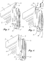
- the canted window 1 shown in the drawing and the following explanation consists essentially of the frame of window frame profiles 2 and two wings, the in Fig. 1 and 3 on the left side, face-plate and the in Fig. 1 and 3 on the right shown walking or opening sash.
- the handle 13 ( Fig. 3 ) is used to open the walking or opening wing. All profiles used in this embodiment have been produced as hollow sections of PVC-U by extrusion.
- the cuff window 1 shown in this embodiment as a center seal system with the center seal 11, 12, an outer stop seal and the inner stop seal 10 three sealing levels.
- Walking or opening wings shown on the right consists of four same, in the miter area welded together standard sash profiles 3 and has - as usual - a reinforcing chamber with inserted steel reinforcement 15 and inner glazing beads 16, which hold the glazing 14 together with the outer arcing 8 ,
- the standard sash profiles 3 have a very low height, so that the sash window 1 extremely narrow View widths.
- the walking or opening wing has on all four sides of an inner wing flashover 29, which rests with the wing closed via an inner stop seal on the frame or on the stop surface 34 of the forend base profile 4.
- the in Fig. 3 In contrast to the opening sash, the fixed leaf shown on the left is welded together from three standard sash profiles 3 and the forend basic profile 4.
- the forend base profile 4 and the sash profiles 3 are first cut mitred and - in the forend area above and below to form a supernatant 26 ( Fig. 4 ) - welded together.
- the inactive leaf points only to the in Fig. 3 left side and top and bottom of an inner wing flashover 29, which rests with the wing closed on an inner stop seal 10 on the frame, in the cuff area this attack on the frame but missing.
- the projections 26 in the upper and lower cuff area are formed from the open miter ends of the inner wing flashover chambers 29 of the upper and lower horizontal sash profiles 3, since this inner wing flashover 29 is absent in the forend basic profile 4.
- the cross-sectional areas of the forend base profile 4 and the sash profile 3 are largely identical, so that when welding these profiles in the miter area the majority of the cross-sectional area is also welded together. As a result, a high corner strength despite the narrow width of the profile profile is achieved.
- the supernatants 26 are removed by machining, in particular by milling or corresponding saw cuts.
- the resulting from the milling 21 open End face regions 33 are then closed by cover caps 7.
- cover caps 7 In the FIGS. 5 and 6 is the upper cap 7 of in Fig. 3 shown on the left.
- the lower cap not shown in the figures, has the same shape, but in a mirrored version.
- Fig. 7 is the face-plate profile 4 shown in cross-section.
- the outside is on the left, the room inside right.
- the outer rollover 8 'corresponds in shape and function to the outer rollover 8 of the sash profile 3 and holds together with the glazing bead 16 and the glazing gasket 9, the glazing 14, wherein in a conventional manner, the sash seal 17 thermally divides the Glasfalz Scheme into two areas.
- the face plate base profile 4 has in many areas the same cross-section as the sash profile 3, in particular, the steel chamber for receiving the steel reinforcement 15 and the fitting groove 27 are identical in shape and location.
- the forend base profile 4 on the inside of the room lacks the inner wing flap 29; instead, a web extending parallel to the glazing 14 forms a stop surface 34 for the inner wing flap 29 of the in-wing flap 29 Fig. 3 right wing shown.
- the hook-shaped cam 18 of the forend base profile 4 corresponds to the corresponding hook-shaped cam 22 of the face-blow bar profile 5, so that both cams 18 and 22 engage one behind the other during assembly.
- the snap-in web 19 of the forend base profile 4 corresponds to the projection 32 of the cuff-bar profile 5. Together, these snap-in bar 19 and the projection 32 form a latching connection.
- the extending between the hook-shaped cam 22 and the projection 32 latching portion of the face-blow bar profile 5 corresponds in shape to the corresponding latching portion 20 between the hook-shaped cam 18 and the locking bar 19 of the forend basic profile 4, said areas through the small cam 35 of the forend Shock profile 5 to form the cavity 31 is kept at a small distance of a few tenths of a millimeter.
- Fig. 7 - 9 the attachment of the forend bar profile 5 is shown on the already welded and milled passive leaf.
- a Klebraupe of commercial PVC adhesive 24 in the latching region 20 between the hook-shaped cam 18 and the latching web 19 of the forend base profile 4 ( Fig. 7 ) applied.
- the face stamp profile 5 is then - as in Fig. 9 illustrated in three phases - positively lockingly connected by means of a rotary movement with the forend basic profile 4, wherein the adhesive 24, the cavity 31 largely fills. Due to the positive latching connection of forend rasp bar profile 5 and forend basic profile 4, the adhesive 24 can cure or dry at rest, without a screw connection would be mandatory.
- connection of the forend bar profile 5 with the forend basic profile 4 - as in Fig. 8 represented - additionally secured by one or more screws 25.
- the bonding of the forend base profile 4 with the face-blow bar profile 5 serves not only the permanently secure connection of these two profiles, but also the seal.
- an additional seal 23 seals the gap between the forend base profile 4 and the forend blow strip profile 5 (FIG. Fig. 9 ).
- Fig. 10 is symbolically illustrated as the cuff caps 6 close the upper and lower open ends of the cuff bar profile 5.
- the cuff cap 6 has on its underside guide or clamping tongues which engage in the hollow chambers of the forehead blow bar profile 5.
- the screws 28 connect the cradles 6 with the forehead rasp profile. 5
Landscapes
- Engineering & Computer Science (AREA)
- Civil Engineering (AREA)
- Structural Engineering (AREA)
- Specific Sealing Or Ventilating Devices For Doors And Windows (AREA)
- Joining Of Corner Units Of Frames Or Wings (AREA)
Abstract
Zur rationellen Herstellung eines Stulpfensters (1) oder einer Stulptür wird ein Profilsystem verwendet, umfassend wenigstens ein Blendrahmenprofil (2), ein Flügelrahmenprofil (3), ein Stulp-Grundprofil (4) und ein Stulp-Schlagleistenprofil (5), wobei das Stulp-Grundprofil (4) und das Stulp-Schlagleistenprofil (5) Mittel zum formschlüssigen Verbinden untereinander umfassen. Als Mittel zum formschlüssigen Verbinden weisen das Stulp-Grundprofil (4) und das Stulp-Schlagleistenprofil (5) jeweils einen im verbundenen Zustand in Wirkverbindung zueinander stehenden, eine Hinterschneidung aufweisenden hakenförmigen Nocken (18, 22) und zusammen ein Paar von im verbundenen Zustand in Wirkverbindung zueinander stehende Rastverbindungsmittel auf. Die hakenförmigen Nocken (18, 22) und die Rastverbindungsmittel sind voneinander beabstandet angeordnet und bilden im Zwischenbereich eine Kavität (31) zur Aufnahme von Klebstoff (24). Zur Herstellung eines Stulpflügels werden das Stulp-Grundprofil (4) und ein Flügelrahmenprofil (3) auf Gehrung geschnitten und im Gehrungsbereich unter Bildung eines Überstands (26) miteinander verschweißt. Der Überstand (26) wird durch spanende Bearbeitung entfernt. Anschließend wird Klebstoff (24) im Bereich zwischen den hakenförmigen Nocken (18, 22) und den Rastverbindungsmitteln (Raststeg 19, Vorsprung 32) auf das Stulp-Grundprofil (4) und/oder das Stulp-Schlagleistenprofil (5) aufgebracht und das Stulp-Schlagleistenprofil (5) mittels einer Drehbewegung mit dem Stulp-Grundprofil (4) rastend verbunden, wobei der Klebstoff (24) die Kavität (31) wenigstens teilweise füllt. Das Verfahren ermöglicht die rationelle Herstellung sowohl von Anschlag- als auch Mitteldichtungssystemen mit sehr schmalen Ansichtsbreiten und hohen Eckfestigkeiten.For the rational production of a custodian window (1) or a sculptured door, a profile system is used, comprising at least one window frame profile (2), a casement profile (3), a forend base profile (4) and a cuff burr profile (5). Base profile (4) and the face-blow bar profile (5) comprise means for positive connection with each other. As a means for positive connection, the forend base profile (4) and the face blow bar profile (5) each have a connected state in operative connection with each other standing, an undercut having hook-shaped cams (18, 22) and together a pair of in the connected state in Actively connected to each other latching connection means. The hook-shaped cams (18, 22) and the latching connection means are arranged at a distance from each other and form in the intermediate region a cavity (31) for receiving adhesive (24). To produce a cuff blade, the forend base profile (4) and a wing frame profile (3) are mitred and welded together in the miter area to form a projection (26). The supernatant (26) is removed by machining. Adhesive (24) is then applied in the region between the hook-shaped cams (18, 22) and the latching connection means (snap-in bar 19, projection 32) to the forend base profile (4) and / or the forend strip profile (5) and the forend Blow bar profile (5) by means of a rotational movement with the face plate base profile (4) connected in a latching manner, wherein the adhesive (24) at least partially fills the cavity (31). The process allows the rational production of both stop and center seal systems with very narrow face widths and high corner strengths.
Description
Die Erfindung betrifft ein Verfahren zur Herstellung eines Stulpfensters bzw. einer Stulptür. Das hierfür verwendete Profilsystem umfasst wenigstens ein Blendrahmenprofil, ein Flügelrahmenprofil, ein Stulp-Grundprofil und ein Stulp-Schlagleistenprofil, wobei das Stulp-Grundprofil und das Stulp-Schlagleistenprofil miteinander formschlüssig verbunden werden.The invention relates to a method for producing a Stulfensters or a sculpted door. The profile system used for this purpose comprises at least one frame profile, a sash profile, a forend basic profile and a forend blow strip profile, wherein the face plate base profile and the face blow bar profile are positively connected to each other.
Stulpflügelfenster oder Stulpfenster bzw. -türen sind Fenster bzw. Türen mit wenigstens zwei Flügeln ohne einen zwischen den Flügeln vertikal verlaufenden Pfosten. Der zuerst zu öffnende Flügel, auch Gehflügel oder Öffnungsflügel genannt, schlägt beim Schließen mit einem inneren Überschlag an den anderen Flügel, gewöhnlich linker Flügel, Lüftungsflügel, Stulpflügel oder Standflügel genannt, an. Soweit im Folgenden und in den Ansprüchen vereinfacht die Begriffe Stulpfenster bzw. Stulpflügelfenster verwendet werden, sind damit auch Stulptüren bzw. Stulpflügeltüren gemeint.Stülpflügelfenster or Stulpfenster or doors are windows or doors with at least two wings without a vertical between the wings post. The first-to-open wing, also called the grand piano or the opening wing, strikes against the other wing, usually called the left wing, the ventilation wing, cuff wing or fixed wing, when it is closed. As far as simplified in the following and in the claims, the terms cuff window or Stulpflügelfenster are used, so are also sculptures or toadstool doors meant.
Üblicherweise werden Kunststoff-Stulpflügelfenster aus Standard-Hohlkammerprofilen hergestellt. Zumindest bei einem der Flügel muss dann der im Stulpbereich störende innere Überschlag, der in den Bereichen außerhalb des Stulpbereichs als Anschlag an den Blendrahmen dient, entfernt werden. Dieses ist mit zusätzlichem Aufwand verbundenen. Außerdem müssen die mit der Entfernung der Profilanschlagkammer entstehenden Nuten oder Grate sorgfältig entfernt und/oder mit einem Abdeckprofil abgedeckt werden. Es sind daher bereits Lösungen mit speziellen Stulp-Grundprofilen bekannt.Usually plastic sash windows are made of standard hollow sections. At least in one of the wings must then disturbing the cuff area inside rollover, which serves as a stop on the frame in the areas outside the cuff area, are removed. This is associated with additional expense. In addition, the grooves or burrs resulting from removal of the profile stopper must be carefully removed and / or covered with a cover profile. Therefore, solutions with special forend basic profiles are already known.
Aus der
Die
Aufgabe der vorliegenden Erfindung ist es, ein weniger Aufwändiges Verfahren zur Herstellung eines Stulpfensters oder einer Stulptür zur Verfügung zu stellen.The object of the present invention is to provide a less complex method for producing a custody window or a sculptured door.
Die Erfindung löst diese Aufgabe durch ein Verfahren nach Anspruch 1, bevorzugt in Verbindung mit einem oder mehreren der Merkmale der Ansprüche 2 und/oder 3.The invention achieves this object by a method according to
Das erfindungsgemäß eingesetzte Profilsystem umfasst neben einem Blendrahmenprofil und einem Flügelrahmenprofil ein Stulp-Grundprofil und ein Stulp-Schlagleistenprofil, wobei das Stulp-Grundprofil und das Stulp-Schlagleistenprofil miteinander formschlüssig verbunden werden können. Als Mittel zum formschlüssigen Verbinden weisen das Stulp-Grundprofil und das Stulp-Schlagleistenprofil jeweils einen im verbundenen Zustand in Wirkverbindung zueinander stehenden, eine Hinterschneidung aufweisenden hakenförmigen Nocken und zusammen ein Paar von im verbundenen Zustand in Wirkverbindung zueinander stehende Rastverbindungsmittel auf. Die hakenförmigen Nocken und die Rastverbindungsmittel sind dabei voneinander beabstandet angeordnet, wobei im Bereich zwischen den hakenförmigen Nocken und den Rastverbindungsmitteln im verbundenen Zustand eine Kavität zur Aufnahme von Klebstoff gebildet wird.The profile system used according to the invention comprises, in addition to a window frame profile and a sash profile, a forend basic profile and a forend blow strip profile, wherein the forend base profile and forend beater strip profile can be positively connected to each other. As a means for positive connection have the forend basic profile and the face blow bar profile each one in the connected state operatively connected to each other, having an undercut hook-shaped cam and together a pair of in the connected state in operative connection to each other standing latching connection means. The hook-shaped cams and the latching connection means are arranged spaced from each other, wherein in the region between the hook-shaped cams and the latching connection means in the connected state, a cavity for receiving adhesive is formed.
Blendrahmenprofil, Flügelrahmenprofil, Stulp-Grundprofil und Stulp-Schlagleistenprofil werden bevorzugt als Hohlkammerprofile aus PVC-U im Extrusionsverfahren hergestellt.The frame profile, casement profile, forend profile and face stamp profile are preferably produced as hollow chamber profiles made of PVC-U by extrusion.
Nach dem erfindungsgemäßen Verfahren werden zur Herstellung des Standflügels drei Flügelrahmenprofile und ein Stulp-Grundprofil zunächst auf Gehrung geschnitten und im Gehrungsbereich unter Bildung eines je eines Überstands im oberen und unteren Stulpbereich miteinander verschweißt. Der Überstand wird durch spanende Bearbeitung, insbesondere durch Fräsen oder durch geeignete Sägeschnitte entfernt. Der durch die spanende Bearbeitung entstehende offene Stirnflächenbereich des Flügelrahmenprofils kann bevorzugt mittels einer Abdeckkappe geschlossen werden.According to the method of the invention, three sash profiles and one forend basic profile are first cut mitred and welded together in the miter area to form one supernatant each in the upper and lower cuff area for the production of the passive leaf. The supernatant is removed by machining, in particular by milling or by suitable saw cuts. The resulting by the machining open face area of the sash profile can preferably be closed by means of a cap.
In dem Bereich zwischen den hakenförmigen Nocken und den Rastverbindungsmitteln wird Klebstoff auf das Stulp-Grundprofil und/oder das Stulp-Schlagleistenprofil aufgebracht und das Stulp-Schlagleistenprofil mittels einer Drehbewegung mit dem Stulp-Grundprofil rastend verbunden, wobei der Klebstoff in die Kavität gedrückt wird und diese wenigstens teilweise füllt.In the area between the hook-shaped cams and the latching connection means adhesive is applied to the forend base profile and / or the face stamp profile and latched the face stamp profile by means of a rotational movement with the forend basic profile, wherein the adhesive is pressed into the cavity and at least partially fills them.
Das erfindungsgemäße Stulp-Schlagleistenprofil und das Stulp Grundprofil sind daher sowohl durch eine Verklebung als auch durch eine formschlüssige mechanische Befestigung miteinander verbunden. Dieses führt sowohl zu einer hohen mechanischen Stabilität als auch zu einer zuverlässigen Abdichtung der beiden Profile untereinander und ist zudem äußerst rationell zu montieren.The cuff-bar profile according to the invention and the cuff base profile are therefore connected to one another both by a bond and by a positive mechanical fastening. This leads both to a high mechanical stability and to a reliable sealing of the two Profiles with each other and is also extremely efficient to assemble.
Das Stulp-Grundprofil und das Stulp-Schlagleistenprofil werden mittels einer Drehbewegung rastend miteinander verbunden.The forend base profile and forend rasp bar profile are connected to one another by means of a rotational movement.
Bevorzugt weist das erfindungsgemäße Profilsystem eine Stulpendkappe zum Verschließen der offenen Enden des Stulp-Schlagleistenprofils und eine Abdeckkappe zum Verschließen des offenen Stirnflächenbereichs des Flügelrahmenprofils auf.The profile system according to the invention preferably has a cuff cap for closing the open ends of the cuff beater bar profile and a cover cap for closing the open end area of the casement profile.
Nach einer besonders bevorzugten Ausführungsform der Erfindung weisen das Stulp-Grundprofil und das Flügelrahmenprofil eine weitgehend übereinstimmende Querschnittsfläche auf. Damit wird sichergestellt, dass beim Verschweißen dieser Profile im Gehrungsbereich der überwiegende Bereich der jeweiligen Querschnittsflächen miteinander verschweißt wird und eine hervorragende Eckfestigkeit erreicht wird. Der Anteil der verschweißten Fläche beträgt bevorzugt mehr als 75 %, besonders bevorzugt mehr als 85 % der Querschnittsfläche des Stulp-Grundprofils.According to a particularly preferred embodiment of the invention, the forend base profile and the sash profile have a substantially matching cross-sectional area. This ensures that the welding of these profiles in the miter area, the vast majority of the respective cross-sectional areas is welded together and an excellent cornering strength is achieved. The proportion of the welded surface is preferably more than 75%, particularly preferably more than 85% of the cross-sectional area of the forend basic profile.
Das erfindungsgemäße Verfahren ermöglicht die rationelle Herstellung sowohl von Anschlag- als auch Mitteldichtungssystemen mit sehr schmalen Ansichtsbreiten und hohen Eckfestigkeiten.The inventive method allows the rational production of both stop and center seal systems with very narrow view widths and high Eckfestigkeiten.
Die Erfindung wird nachfolgend anhand eines Ausführungsbeispiels sowie der Zeichnung näher erläutert. Es zeigen dabei:
- Fig. 1
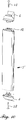
- eine Innenansicht eines erfindungsgemäßen Stulpfensters;
- Fig. 2
- die entsprechende Außenansicht des Stulpfensters gemäß
Fig. 1 ; - Fig. 3
- einen Horizontalschnitt durch das Stulpfenster gemäß
Fig. 1 ;und 2 - Fig. 4
- eine perspektivische Innenansicht des oberen Eckbereichs des Standflügels nach dem Verschweißen im Gehrungsbereich;
- Fig. 5
- eine perspektivische Innenansicht des oberen Eckbereichs des Standflügels nach dem Fräsen des Überstandes;
- Fig. 6
- eine perspektivische Innenansicht des oberen Eckbereichs des Standflügels nach dem Aufsetzen der Abdeckkappe;
- Fig. 7
- einen Schnitt durch das Stulp-Grundprofil;
- Fig. 8
- einen Schnitt durch das Stulp-Grundprofil und das Stulp-Schlagleistenprofil nach dem Verbinden;
- Fig. 9
- drei Schnitte in verschiedenen Phasen durch das Stulp-Grundprofil und das Stulp-Schlagleistenprofil beim Verbinden;
- Fig. 10
- eine perspektivische Ansicht des Stulp-Schlagleistenprofils mit Stulpendkappen;
- Fig. 1
- an interior view of a Stulfensters invention;
- Fig. 2
- the corresponding external view of the Stulfensters according to
Fig. 1 ; - Fig. 3
- a horizontal section through the cuff window according to
Fig. 1 and 2 ; - Fig. 4
- an inside perspective view of the upper corner portion of the inactive leaf after welding in the miter area;
- Fig. 5
- an inside perspective view of the upper corner portion of the passive leaf after milling the supernatant;
- Fig. 6
- an inside perspective view of the upper corner portion of the inactive leaf after placing the cap;
- Fig. 7
- a section through the forend basic profile;
- Fig. 8
- a section through the forend base profile and forend rasp bar profile after joining;
- Fig. 9
- three cuts in different phases through the forend base profile and forend rasp bar profile when joining;
- Fig. 10
- a perspective view of the face blow bar profile with cuff caps;
Das in der Zeichnung und der nachfolgenden Erläuterung dargestellte Stulpfenster 1 besteht im Wesentlichen aus dem Blendrahmen aus Blendrahmenprofilen 2 sowie zwei Flügeln, dem in
Der im Schnitt (
Der in
Die Überstände 26 im oberen und unteren Stulpbereich werden gebildet aus den offenen Gehrungsenden der inneren Flügelüberschlagskammern 29 der oberen und unteren waagerechten Flügelrahmenprofile 3, da dieser innere Flügelüberschlag 29 bei dem Stulp-Grundprofil 4 fehlt.The
Mit Ausnahme der Flügelüberschlagskammer 29 und dem unmittelbar daran anschließenden Bereich zwischen der Beschlagsnut 27 und der Innensichtfläche sowie dem hakenförmigen Nocken 18 und dem Raststeg 19 sind die Querschnittsflächen des Stulp-Grundprofils 4 und des Flügelrahmenprofils 3 weitgehend identisch, so dass beim Verschweißen dieser Profile im Gehrungsbereich der überwiegende Anteil der Querschnittsfläche auch miteinander verschweißt wird. Hierdurch wird eine hohe Eckfestigkeit trotz der schmalen Ansichtsbreite der Profile erreicht.With the exception of the
Nach dem Verschweißen werden die Überstände 26 durch spanende Bearbeitung, insbesondere durch Fräsen oder entsprechende Sägeschnitte, entfernt. Die durch die Fräsung 21 entstehenden offenen Stirnflächenbereiche 33 werden anschließend durch Abdeckkappen 7 verschlossen. In den
In
Der sich zwischen dem hakenförmigen Nocken 22 und dem Vorsprung 32 erstreckende Rastbereich des Stulp-Schlagleistenprofils 5 entspricht in seiner Form dem entsprechenden Rastbereich 20 zwischen dem hakenförmigen Nocken 18 und dem Raststeg 19 des Stulp Grundprofil 4, wobei diese Bereiche durch den kleinen Nocken 35 des Stulp-Schlagleistenprofils 5 unter Bildung der Kavität 31 auf einen geringen Abstand von einigen Zehntel Millimeter gehalten wird.The extending between the hook-shaped
In den
In
- 11
- StulpfensterOpening window
- 22
- BlendrahmenprofilFrame profile
- 33
- FlügelrahmenprofilCasement profile
- 44
- Stulp-GrundprofilStulp basic profile
- 55
- Stulp-SchlagleistenprofilStulp impact strip profile
- 66
- StulpendkappeStulpendkappe
- 77
- Abdeckkappe ÜberschlagCover flap
- 8 , 8'8, 8 '
- äußerer Überschlag (Flügelrahmenprofil)outer rollover (sash profile)
- 99
- Verglasungsdichtungglazing gasket
- 1010
- innere Anschlagsdichtunginner stop seal
- 1111
- MitteldichtungCenter seal
- 1212
- Mitteldichtung StulpprofilCenter seal face profile
- 1313
- GriffHandle
- 1414
- Verglasungglazing
- 1515
- Stahlverstärkungsteel reinforcement
- 1616
- Glasleisteglazing bead
- 1717
- Flügelfalzdichtungsash
- 1818
- hakenförmiger Nockenhook-shaped cam
- 1919
- Raststeglatching web
- 2020
- RastbereichRest area
- 2121
- Fräsungmilling
- 2222
- hakenförmiger Nockenhook-shaped cam
- 2323
- Dichtungpoetry
- 2424
- Klebstoffadhesive
- 2525
- Schraubescrew
- 2626
- ÜberstandGot over
- 2727
- Beschlagsnutfittings groove
- 2828
- Schraubescrew
- 2929
- innerer Flügelüberschlaginner wing flap
- 3030
- entfälltdeleted
- 3131
- Kavität zur KlebstoffaufnahmeCavity for adhesive absorption
- 3232
- Vorsprunghead Start
- 3333
- offener Stirnflächenbereichopen face area
- 3434
- Anschlagflächestop surface
- 3535
- Nockencam
Claims (3)
wobei das Stulp-Grundprofil (4) und das Stulp-Schlagleistenprofil (5) als Mittel zum formschlüssigen Verbinden
gekennzeichnet durch folgende Verfahrensschritte:
wherein the face-plate base profile (4) and the face-blow bar profile (5) as a means for positive connection
characterized by the following process steps:
Applications Claiming Priority (1)
| Application Number | Priority Date | Filing Date | Title |
|---|---|---|---|
| EP16150003.8A EP3187676A1 (en) | 2016-01-01 | 2016-01-01 | Profile system and method for producing a double leaf window |
Publications (2)
| Publication Number | Publication Date |
|---|---|
| EP3187677A1 true EP3187677A1 (en) | 2017-07-05 |
| EP3187677B1 EP3187677B1 (en) | 2020-01-01 |
Family
ID=55072514
Family Applications (2)
| Application Number | Title | Priority Date | Filing Date |
|---|---|---|---|
| EP16150003.8A Withdrawn EP3187676A1 (en) | 2016-01-01 | 2016-01-01 | Profile system and method for producing a double leaf window |
| EP17150076.2A Active EP3187677B1 (en) | 2016-01-01 | 2017-01-02 | Method for producing a battery french casement window |
Family Applications Before (1)
| Application Number | Title | Priority Date | Filing Date |
|---|---|---|---|
| EP16150003.8A Withdrawn EP3187676A1 (en) | 2016-01-01 | 2016-01-01 | Profile system and method for producing a double leaf window |
Country Status (2)
| Country | Link |
|---|---|
| EP (2) | EP3187676A1 (en) |
| DE (1) | DE102017100031A1 (en) |
Cited By (3)
| Publication number | Priority date | Publication date | Assignee | Title |
|---|---|---|---|---|
| GB2561582A (en) * | 2017-04-19 | 2018-10-24 | Veka Plc | Window, stile and cover bar |
| FR3080138A1 (en) * | 2018-04-13 | 2019-10-18 | Selo Sarl | EFFICIENT CLOSURE SYSTEM FOR DEPRESSION |
| CN111998762B (en) * | 2020-10-29 | 2021-03-30 | 支付宝(杭州)信息技术有限公司 | Cabinet and method for detecting closing of cabinet door |
Citations (2)
| Publication number | Priority date | Publication date | Assignee | Title |
|---|---|---|---|---|
| GB2166792A (en) | 1984-09-18 | 1986-05-14 | Repol Polyester Produkte Gmbh | Window frames |
| DE10155475A1 (en) | 2001-11-12 | 2003-05-22 | Unilux Ag | Window and door frame arrangements have first and second frames with profiled bars and holders closed by layers of material |
-
2016
- 2016-01-01 EP EP16150003.8A patent/EP3187676A1/en not_active Withdrawn
-
2017
- 2017-01-02 EP EP17150076.2A patent/EP3187677B1/en active Active
- 2017-01-02 DE DE102017100031.3A patent/DE102017100031A1/en not_active Withdrawn
Patent Citations (2)
| Publication number | Priority date | Publication date | Assignee | Title |
|---|---|---|---|---|
| GB2166792A (en) | 1984-09-18 | 1986-05-14 | Repol Polyester Produkte Gmbh | Window frames |
| DE10155475A1 (en) | 2001-11-12 | 2003-05-22 | Unilux Ag | Window and door frame arrangements have first and second frames with profiled bars and holders closed by layers of material |
Cited By (3)
| Publication number | Priority date | Publication date | Assignee | Title |
|---|---|---|---|---|
| GB2561582A (en) * | 2017-04-19 | 2018-10-24 | Veka Plc | Window, stile and cover bar |
| FR3080138A1 (en) * | 2018-04-13 | 2019-10-18 | Selo Sarl | EFFICIENT CLOSURE SYSTEM FOR DEPRESSION |
| CN111998762B (en) * | 2020-10-29 | 2021-03-30 | 支付宝(杭州)信息技术有限公司 | Cabinet and method for detecting closing of cabinet door |
Also Published As
| Publication number | Publication date |
|---|---|
| EP3187677B1 (en) | 2020-01-01 |
| EP3187676A1 (en) | 2017-07-05 |
| DE102017100031A1 (en) | 2017-07-06 |
| DE102017100031A8 (en) | 2017-08-24 |
Similar Documents
| Publication | Publication Date | Title |
|---|---|---|
| EP3187677B1 (en) | Method for producing a battery french casement window | |
| EP2689086B1 (en) | System for producing a double leaf window and mullion cap for same | |
| EP0202510B1 (en) | Outer frame or wing frame for windows or doors | |
| EP1877640A1 (en) | Frame for a window or a door | |
| EP2947217B1 (en) | Insulation block for a window or the like | |
| EP1801342A1 (en) | Profile system made of plastics for a window or door | |
| DE202008011056U1 (en) | Building window or building door and curb compensation part for use in a building window or a building door | |
| EP0011124B2 (en) | Door or window | |
| EP0082338B1 (en) | Compound window | |
| DE102008054921A1 (en) | Window with glare and sash frame | |
| EP3181795B1 (en) | Method for connecting two holow-chamber sections having different cross-sections | |
| DE3934265A1 (en) | Frames for doors and casement windows - are made from wood with fixed and hinged frames having common contours | |
| DE102006062161A1 (en) | Window or door with a frame profile system comprises a frame made from plastic frame profiles with a mounting groove in the folding region | |
| EP0459084B1 (en) | Kit for the construction of windows | |
| DE19609624C2 (en) | Building window and / or building window door | |
| EP3190255B1 (en) | End cap and its use | |
| EP0794311A1 (en) | Astragal for double leaf window | |
| DE2511331B2 (en) | PRESSURE COMPENSATION CONTROL | |
| DE102014103650A1 (en) | Method and profile system for the production of building windows, building doors | |
| DE19622725C2 (en) | Building window and / or building window door | |
| DE102011102912B4 (en) | Skylights, frames and casement frames and methods of manufacturing the same | |
| DE2326219A1 (en) | WINDOW, DOOR OR THE SAME COMPONENT | |
| DE19947108A1 (en) | Windows and process for their manufacture | |
| DE102016124443A1 (en) | Method for connecting two hollow chamber profiles of different cross-section | |
| DE102016116954A1 (en) | Method for producing a frame connection |
Legal Events
| Date | Code | Title | Description |
|---|---|---|---|
| PUAI | Public reference made under article 153(3) epc to a published international application that has entered the european phase |
Free format text: ORIGINAL CODE: 0009012 |
|
| STAA | Information on the status of an ep patent application or granted ep patent |
Free format text: STATUS: THE APPLICATION HAS BEEN PUBLISHED |
|
| AK | Designated contracting states |
Kind code of ref document: A1 Designated state(s): AL AT BE BG CH CY CZ DE DK EE ES FI FR GB GR HR HU IE IS IT LI LT LU LV MC MK MT NL NO PL PT RO RS SE SI SK SM TR |
|
| AX | Request for extension of the european patent |
Extension state: BA ME |
|
| STAA | Information on the status of an ep patent application or granted ep patent |
Free format text: STATUS: REQUEST FOR EXAMINATION WAS MADE |
|
| 17P | Request for examination filed |
Effective date: 20180105 |
|
| RBV | Designated contracting states (corrected) |
Designated state(s): AL AT BE BG CH CY CZ DE DK EE ES FI FR GB GR HR HU IE IS IT LI LT LU LV MC MK MT NL NO PL PT RO RS SE SI SK SM TR |
|
| GRAP | Despatch of communication of intention to grant a patent |
Free format text: ORIGINAL CODE: EPIDOSNIGR1 |
|
| STAA | Information on the status of an ep patent application or granted ep patent |
Free format text: STATUS: GRANT OF PATENT IS INTENDED |
|
| INTG | Intention to grant announced |
Effective date: 20190523 |
|
| GRAS | Grant fee paid |
Free format text: ORIGINAL CODE: EPIDOSNIGR3 |
|
| GRAA | (expected) grant |
Free format text: ORIGINAL CODE: 0009210 |
|
| STAA | Information on the status of an ep patent application or granted ep patent |
Free format text: STATUS: THE PATENT HAS BEEN GRANTED |
|
| AK | Designated contracting states |
Kind code of ref document: B1 Designated state(s): AL AT BE BG CH CY CZ DE DK EE ES FI FR GB GR HR HU IE IS IT LI LT LU LV MC MK MT NL NO PL PT RO RS SE SI SK SM TR |
|
| REG | Reference to a national code |
Ref country code: GB Ref legal event code: FG4D Free format text: NOT ENGLISH |
|
| REG | Reference to a national code |
Ref country code: AT Ref legal event code: REF Ref document number: 1219964 Country of ref document: AT Kind code of ref document: T Effective date: 20200115 Ref country code: CH Ref legal event code: EP |
|
| REG | Reference to a national code |
Ref country code: DE Ref legal event code: R096 Ref document number: 502017003304 Country of ref document: DE |
|
| REG | Reference to a national code |
Ref country code: IE Ref legal event code: FG4D Free format text: LANGUAGE OF EP DOCUMENT: GERMAN |
|
| REG | Reference to a national code |
Ref country code: CH Ref legal event code: NV Representative=s name: TR-IP CONSULTING LLC, CH |
|
| REG | Reference to a national code |
Ref country code: NL Ref legal event code: MP Effective date: 20200101 |
|
| REG | Reference to a national code |
Ref country code: LT Ref legal event code: MG4D |
|
| PG25 | Lapsed in a contracting state [announced via postgrant information from national office to epo] |
Ref country code: CZ Free format text: LAPSE BECAUSE OF FAILURE TO SUBMIT A TRANSLATION OF THE DESCRIPTION OR TO PAY THE FEE WITHIN THE PRESCRIBED TIME-LIMIT Effective date: 20200101 Ref country code: PT Free format text: LAPSE BECAUSE OF FAILURE TO SUBMIT A TRANSLATION OF THE DESCRIPTION OR TO PAY THE FEE WITHIN THE PRESCRIBED TIME-LIMIT Effective date: 20200527 Ref country code: NL Free format text: LAPSE BECAUSE OF FAILURE TO SUBMIT A TRANSLATION OF THE DESCRIPTION OR TO PAY THE FEE WITHIN THE PRESCRIBED TIME-LIMIT Effective date: 20200101 Ref country code: LT Free format text: LAPSE BECAUSE OF FAILURE TO SUBMIT A TRANSLATION OF THE DESCRIPTION OR TO PAY THE FEE WITHIN THE PRESCRIBED TIME-LIMIT Effective date: 20200101 Ref country code: RS Free format text: LAPSE BECAUSE OF FAILURE TO SUBMIT A TRANSLATION OF THE DESCRIPTION OR TO PAY THE FEE WITHIN THE PRESCRIBED TIME-LIMIT Effective date: 20200101 Ref country code: FI Free format text: LAPSE BECAUSE OF FAILURE TO SUBMIT A TRANSLATION OF THE DESCRIPTION OR TO PAY THE FEE WITHIN THE PRESCRIBED TIME-LIMIT Effective date: 20200101 Ref country code: NO Free format text: LAPSE BECAUSE OF FAILURE TO SUBMIT A TRANSLATION OF THE DESCRIPTION OR TO PAY THE FEE WITHIN THE PRESCRIBED TIME-LIMIT Effective date: 20200401 |
|
| PG25 | Lapsed in a contracting state [announced via postgrant information from national office to epo] |
Ref country code: BG Free format text: LAPSE BECAUSE OF FAILURE TO SUBMIT A TRANSLATION OF THE DESCRIPTION OR TO PAY THE FEE WITHIN THE PRESCRIBED TIME-LIMIT Effective date: 20200401 Ref country code: IS Free format text: LAPSE BECAUSE OF FAILURE TO SUBMIT A TRANSLATION OF THE DESCRIPTION OR TO PAY THE FEE WITHIN THE PRESCRIBED TIME-LIMIT Effective date: 20200501 Ref country code: HR Free format text: LAPSE BECAUSE OF FAILURE TO SUBMIT A TRANSLATION OF THE DESCRIPTION OR TO PAY THE FEE WITHIN THE PRESCRIBED TIME-LIMIT Effective date: 20200101 Ref country code: GR Free format text: LAPSE BECAUSE OF FAILURE TO SUBMIT A TRANSLATION OF THE DESCRIPTION OR TO PAY THE FEE WITHIN THE PRESCRIBED TIME-LIMIT Effective date: 20200402 Ref country code: LV Free format text: LAPSE BECAUSE OF FAILURE TO SUBMIT A TRANSLATION OF THE DESCRIPTION OR TO PAY THE FEE WITHIN THE PRESCRIBED TIME-LIMIT Effective date: 20200101 Ref country code: SE Free format text: LAPSE BECAUSE OF FAILURE TO SUBMIT A TRANSLATION OF THE DESCRIPTION OR TO PAY THE FEE WITHIN THE PRESCRIBED TIME-LIMIT Effective date: 20200101 |
|
| REG | Reference to a national code |
Ref country code: DE Ref legal event code: R097 Ref document number: 502017003304 Country of ref document: DE |
|
| REG | Reference to a national code |
Ref country code: BE Ref legal event code: MM Effective date: 20200131 |
|
| PG25 | Lapsed in a contracting state [announced via postgrant information from national office to epo] |
Ref country code: SK Free format text: LAPSE BECAUSE OF FAILURE TO SUBMIT A TRANSLATION OF THE DESCRIPTION OR TO PAY THE FEE WITHIN THE PRESCRIBED TIME-LIMIT Effective date: 20200101 Ref country code: MC Free format text: LAPSE BECAUSE OF FAILURE TO SUBMIT A TRANSLATION OF THE DESCRIPTION OR TO PAY THE FEE WITHIN THE PRESCRIBED TIME-LIMIT Effective date: 20200101 Ref country code: EE Free format text: LAPSE BECAUSE OF FAILURE TO SUBMIT A TRANSLATION OF THE DESCRIPTION OR TO PAY THE FEE WITHIN THE PRESCRIBED TIME-LIMIT Effective date: 20200101 Ref country code: SM Free format text: LAPSE BECAUSE OF FAILURE TO SUBMIT A TRANSLATION OF THE DESCRIPTION OR TO PAY THE FEE WITHIN THE PRESCRIBED TIME-LIMIT Effective date: 20200101 Ref country code: DK Free format text: LAPSE BECAUSE OF FAILURE TO SUBMIT A TRANSLATION OF THE DESCRIPTION OR TO PAY THE FEE WITHIN THE PRESCRIBED TIME-LIMIT Effective date: 20200101 Ref country code: LU Free format text: LAPSE BECAUSE OF NON-PAYMENT OF DUE FEES Effective date: 20200102 Ref country code: ES Free format text: LAPSE BECAUSE OF FAILURE TO SUBMIT A TRANSLATION OF THE DESCRIPTION OR TO PAY THE FEE WITHIN THE PRESCRIBED TIME-LIMIT Effective date: 20200101 Ref country code: RO Free format text: LAPSE BECAUSE OF FAILURE TO SUBMIT A TRANSLATION OF THE DESCRIPTION OR TO PAY THE FEE WITHIN THE PRESCRIBED TIME-LIMIT Effective date: 20200101 |
|
| PLBE | No opposition filed within time limit |
Free format text: ORIGINAL CODE: 0009261 |
|
| STAA | Information on the status of an ep patent application or granted ep patent |
Free format text: STATUS: NO OPPOSITION FILED WITHIN TIME LIMIT |
|
| PG25 | Lapsed in a contracting state [announced via postgrant information from national office to epo] |
Ref country code: BE Free format text: LAPSE BECAUSE OF NON-PAYMENT OF DUE FEES Effective date: 20200131 |
|
| 26N | No opposition filed |
Effective date: 20201002 |
|
| PG25 | Lapsed in a contracting state [announced via postgrant information from national office to epo] |
Ref country code: IE Free format text: LAPSE BECAUSE OF NON-PAYMENT OF DUE FEES Effective date: 20200102 |
|
| PG25 | Lapsed in a contracting state [announced via postgrant information from national office to epo] |
Ref country code: PL Free format text: LAPSE BECAUSE OF FAILURE TO SUBMIT A TRANSLATION OF THE DESCRIPTION OR TO PAY THE FEE WITHIN THE PRESCRIBED TIME-LIMIT Effective date: 20200101 Ref country code: SI Free format text: LAPSE BECAUSE OF FAILURE TO SUBMIT A TRANSLATION OF THE DESCRIPTION OR TO PAY THE FEE WITHIN THE PRESCRIBED TIME-LIMIT Effective date: 20200101 |
|
| GBPC | Gb: european patent ceased through non-payment of renewal fee |
Effective date: 20210102 |
|
| PG25 | Lapsed in a contracting state [announced via postgrant information from national office to epo] |
Ref country code: GB Free format text: LAPSE BECAUSE OF NON-PAYMENT OF DUE FEES Effective date: 20210102 |
|
| PG25 | Lapsed in a contracting state [announced via postgrant information from national office to epo] |
Ref country code: TR Free format text: LAPSE BECAUSE OF FAILURE TO SUBMIT A TRANSLATION OF THE DESCRIPTION OR TO PAY THE FEE WITHIN THE PRESCRIBED TIME-LIMIT Effective date: 20200101 Ref country code: MT Free format text: LAPSE BECAUSE OF FAILURE TO SUBMIT A TRANSLATION OF THE DESCRIPTION OR TO PAY THE FEE WITHIN THE PRESCRIBED TIME-LIMIT Effective date: 20200101 Ref country code: CY Free format text: LAPSE BECAUSE OF FAILURE TO SUBMIT A TRANSLATION OF THE DESCRIPTION OR TO PAY THE FEE WITHIN THE PRESCRIBED TIME-LIMIT Effective date: 20200101 |
|
| PG25 | Lapsed in a contracting state [announced via postgrant information from national office to epo] |
Ref country code: MK Free format text: LAPSE BECAUSE OF FAILURE TO SUBMIT A TRANSLATION OF THE DESCRIPTION OR TO PAY THE FEE WITHIN THE PRESCRIBED TIME-LIMIT Effective date: 20200101 Ref country code: AL Free format text: LAPSE BECAUSE OF FAILURE TO SUBMIT A TRANSLATION OF THE DESCRIPTION OR TO PAY THE FEE WITHIN THE PRESCRIBED TIME-LIMIT Effective date: 20200101 |
|
| REG | Reference to a national code |
Ref country code: DE Ref legal event code: R081 Ref document number: 502017003304 Country of ref document: DE Owner name: PROFINE GMBH, DE Free format text: FORMER OWNER: PROFINE GMBH, 53840 TROISDORF, DE |
|
| PGFP | Annual fee paid to national office [announced via postgrant information from national office to epo] |
Ref country code: AT Payment date: 20240122 Year of fee payment: 8 |
|
| PGFP | Annual fee paid to national office [announced via postgrant information from national office to epo] |
Ref country code: DE Payment date: 20240119 Year of fee payment: 8 Ref country code: CH Payment date: 20240202 Year of fee payment: 8 |
|
| PGFP | Annual fee paid to national office [announced via postgrant information from national office to epo] |
Ref country code: IT Payment date: 20240129 Year of fee payment: 8 Ref country code: FR Payment date: 20240124 Year of fee payment: 8 |