EP3183202B1 - Aktuator in einem gabelstapler - Google Patents
Aktuator in einem gabelstapler Download PDFInfo
- Publication number
- EP3183202B1 EP3183202B1 EP15756754.6A EP15756754A EP3183202B1 EP 3183202 B1 EP3183202 B1 EP 3183202B1 EP 15756754 A EP15756754 A EP 15756754A EP 3183202 B1 EP3183202 B1 EP 3183202B1
- Authority
- EP
- European Patent Office
- Prior art keywords
- ram
- cylinder
- seal
- gap
- actuator
- Prior art date
- Legal status (The legal status is an assumption and is not a legal conclusion. Google has not performed a legal analysis and makes no representation as to the accuracy of the status listed.)
- Active
Links
Images






Classifications
-
- B—PERFORMING OPERATIONS; TRANSPORTING
- B66—HOISTING; LIFTING; HAULING
- B66F—HOISTING, LIFTING, HAULING OR PUSHING, NOT OTHERWISE PROVIDED FOR, e.g. DEVICES WHICH APPLY A LIFTING OR PUSHING FORCE DIRECTLY TO THE SURFACE OF A LOAD
- B66F9/00—Devices for lifting or lowering bulky or heavy goods for loading or unloading purposes
- B66F9/06—Devices for lifting or lowering bulky or heavy goods for loading or unloading purposes movable, with their loads, on wheels or the like, e.g. fork-lift trucks
- B66F9/075—Constructional features or details
- B66F9/20—Means for actuating or controlling masts, platforms, or forks
- B66F9/22—Hydraulic devices or systems
-
- F—MECHANICAL ENGINEERING; LIGHTING; HEATING; WEAPONS; BLASTING
- F15—FLUID-PRESSURE ACTUATORS; HYDRAULICS OR PNEUMATICS IN GENERAL
- F15B—SYSTEMS ACTING BY MEANS OF FLUIDS IN GENERAL; FLUID-PRESSURE ACTUATORS, e.g. SERVOMOTORS; DETAILS OF FLUID-PRESSURE SYSTEMS, NOT OTHERWISE PROVIDED FOR
- F15B15/00—Fluid-actuated devices for displacing a member from one position to another; Gearing associated therewith
- F15B15/08—Characterised by the construction of the motor unit
- F15B15/14—Characterised by the construction of the motor unit of the straight-cylinder type
-
- F—MECHANICAL ENGINEERING; LIGHTING; HEATING; WEAPONS; BLASTING
- F15—FLUID-PRESSURE ACTUATORS; HYDRAULICS OR PNEUMATICS IN GENERAL
- F15B—SYSTEMS ACTING BY MEANS OF FLUIDS IN GENERAL; FLUID-PRESSURE ACTUATORS, e.g. SERVOMOTORS; DETAILS OF FLUID-PRESSURE SYSTEMS, NOT OTHERWISE PROVIDED FOR
- F15B15/00—Fluid-actuated devices for displacing a member from one position to another; Gearing associated therewith
- F15B15/08—Characterised by the construction of the motor unit
- F15B15/14—Characterised by the construction of the motor unit of the straight-cylinder type
- F15B15/1423—Component parts; Constructional details
- F15B15/1457—Piston rods
- F15B15/1461—Piston rod sealings
-
- F—MECHANICAL ENGINEERING; LIGHTING; HEATING; WEAPONS; BLASTING
- F15—FLUID-PRESSURE ACTUATORS; HYDRAULICS OR PNEUMATICS IN GENERAL
- F15B—SYSTEMS ACTING BY MEANS OF FLUIDS IN GENERAL; FLUID-PRESSURE ACTUATORS, e.g. SERVOMOTORS; DETAILS OF FLUID-PRESSURE SYSTEMS, NOT OTHERWISE PROVIDED FOR
- F15B15/00—Fluid-actuated devices for displacing a member from one position to another; Gearing associated therewith
- F15B15/20—Other details, e.g. assembly with regulating devices
- F15B15/22—Other details, e.g. assembly with regulating devices for accelerating or decelerating the stroke
- F15B15/227—Other details, e.g. assembly with regulating devices for accelerating or decelerating the stroke having an auxiliary cushioning piston within the main piston or the cylinder end face
-
- F—MECHANICAL ENGINEERING; LIGHTING; HEATING; WEAPONS; BLASTING
- F16—ENGINEERING ELEMENTS AND UNITS; GENERAL MEASURES FOR PRODUCING AND MAINTAINING EFFECTIVE FUNCTIONING OF MACHINES OR INSTALLATIONS; THERMAL INSULATION IN GENERAL
- F16F—SPRINGS; SHOCK-ABSORBERS; MEANS FOR DAMPING VIBRATION
- F16F9/00—Springs, vibration-dampers, shock-absorbers, or similarly-constructed movement-dampers using a fluid or the equivalent as damping medium
- F16F9/32—Details
- F16F9/48—Arrangements for providing different damping effects at different parts of the stroke
- F16F9/49—Stops limiting fluid passage, e.g. hydraulic stops or elastomeric elements inside the cylinder which contribute to changes in fluid damping
-
- F—MECHANICAL ENGINEERING; LIGHTING; HEATING; WEAPONS; BLASTING
- F16—ENGINEERING ELEMENTS AND UNITS; GENERAL MEASURES FOR PRODUCING AND MAINTAINING EFFECTIVE FUNCTIONING OF MACHINES OR INSTALLATIONS; THERMAL INSULATION IN GENERAL
- F16J—PISTONS; CYLINDERS; SEALINGS
- F16J15/00—Sealings
- F16J15/16—Sealings between relatively-moving surfaces
Definitions
- the present invention relates to an actuator in a lift truck and more specifically to an actuator having a cushioning seal, which functions to substantially close off a first portion of a gap between a ram structure and a cylinder structure during ram structure extension and allows fluid to flow between the seal and the cylinder structure during ram retraction.
- U.S. Patent No. 4,706,781 discloses a load lifting cylinder having a lateral hole 119, which communicates with a bore 106 of a piston element 105, see Figs. 4-6 .
- a piston rod 107 is coupled to the piston element 105.
- the '781 patent teaches in column 8, lines 23-34: "When the piston element 105 approaches the uppermost position, and the lateral hole 119 is closed by the rod guide 116, the working fluid in the upper cylinder chamber 104B is permitted to leak out of the chamber 104B into the bottom cylinder chamber 104A only via the small hole 118. That is, the flow rate is extremely limited, due to the closure of the lateral hole 119.
- JP 2000055010 A describes a ram cylinder including a ram structure slidable within a cylinder structure and defining a first chamber between a piston of the ram structure and a cylinder end, and a second chamber formed by a gap between the ram structure and the cylinder structure.
- a fluid passage formed in the ram structure permits fluid to pass between the first and second chambers, and a seal on the cylinder structure closes off the fluid passage as the ram structure approaches the end of its extension from the cylinder structure.
- an actuator in a lift truck having an extendible mast may comprise: cylinder structure, ram structure and a cushioning seal.
- the cylinder structure may comprise a cylinder tube, a cylinder base and a cylinder cap.
- the base and cap may be coupled to the tube.
- the tube and cap may define a cylinder structure bore extending from the base to an outer open end of the cylinder structure.
- the ram structure is slidably mounted within the cylinder structure bore and defines with the cylinder structure a gap therebetween.
- the ram structure may comprise fluid passageway structure for defining a path for fluid to move internally through the ram structure. The path may communicate with an outlet in a sidewall of the ram structure.
- the cushioning seal may be located between the ram structure and the cylinder structure and engage the ram structure and the cylinder cap during ram structure extension such that the seal substantially closes off a first portion of the gap extending from the seal toward the cylinder structure outer open end.
- the cushioning seal may be moved during ram structure retraction in a direction of ram structure retraction such that fluid flowing out of the ram structure sidewall outlet when the outlet is in the gap first portion flows between the seal and the cap.
- the cap may comprise an internal recess for receiving the cushioning seal.
- the recess may have an axial dimension greater than an axial dimension of the seal and a radial dimension greater than a radial dimension of the seal.
- the seal may be formed from metal. The seal may be movable within the recess in a direction toward or away from the cylinder structure outer open end.
- the seal may comprise a main body comprising an axially extending stepped slot so as to allow the seal to expand outwardly, with the seal main body having an unexpanded inner diameter which is slightly smaller than an outer diameter of the ram structure such that the seal is expanded slightly to be fitted over the ram structure.
- the cap comprises first and second ends.
- the second end may define the cylinder structure outer open end.
- the first end may comprise one or more grooves through which fluid passes into a first section of the gap generally defined by a ram element of the ram structure and the cylinder tube during ram structure retraction when the outlet is in the gap first portion.
- An inner diameter of the cylinder cap may be smaller than an inner diameter of the cylinder tube such that the first section of the gap defined by the ram element and the cylinder tube is larger than a second section of the gap defined by the ram element and the cylinder cap.
- the cylinder cap of a further embodiment may comprise first and second ends, the second end defining the cylinder structure outer open end, the first end comprising an angled inner surface.
- the seal of the further embodiment may comprise a main body comprising an inner sidewall and an angled outer sidewall.
- the seal may be urged by fluid during ram structure extension such that the seal main body inner sidewall engages the ram structure and the seal main body angled outer sidewall engages the cylinder cap first end angled inner surface such that the seal substantially closes off the gap first portion.
- the seal main body may further comprise at least one groove through which fluid passes into a first section of the gap defined by a ram element of the ram structure and the cylinder tube during ram structure retraction when the outlet is in the gap first portion.
- An inner diameter of the cylinder cap may be smaller than an inner diameter of the cylinder tube such that the first section of the gap defined by the ram element and the cylinder tube is larger than a second section of the gap defined by the ram element and the cylinder cap.
- the seal may be formed from a polymeric material.
- An orifice may be provided in the ram structure sidewall so as to communicate with the outlet and extends away from the outlet in a direction towards the cylinder base.
- the orifice may provide a path for fluid to flow from a first section of the gap defined by a ram element of the ram structure and the cylinder tube into the outlet during ram structure extension.
- the outlet may be provided in the ram element.
- the orifice may be shaped such that the resistance to fluid flow from the gap first section into the outlet increases as the outlet moves adjacent to and beyond the seal causing pressure to gradually increase in the gap first section resulting in the ram structure decelerating at a substantially smooth rate at the end of ram structure extension.
- the orifice may comprise a tear-drop shaped orifice.
- the ram structure may comprise a ram element and a piston coupled to the ram element.
- the ram element may have a first outer diameter and the piston may have a second outer diameter greater than the first outer diameter.
- the gap may comprise a first section generally defined radially by the ram element of the ram structure and the cylinder tube and may extend axially between the piston and a first end of the cylinder cap.
- a second section of the gap may generally be defined radially by the ram element and the cylinder cap and extend axially from the first end of the cylinder cap to a ram element seal.
- the fluid passage structure may comprise an axially extending bore provided in a ram element of the ram structure which communicates with the cylinder base and a radially extending bore in the ram element which communicates with the axially extending bore and the outlet.
- the outlet may be provided in a sidewall of the ram element.
- Fluid may only enter the cylinder structure through the cylinder base.
- the present disclosure provides an improved cushioning system to reduce shock forces as a ram of a primary ram and cylinder assembly 10 reaches the end of its stroke and as the rams of first and second secondary ram and cylinder assemblies 200 and 210 begin to move upward.
- the primary ram and cylinder assembly 10 and the first and second secondary ram and cylinder assemblies 200 and 210 may be provided in a materials handling vehicle comprising, for example, a stand-up or sit down counter balance truck, a narrow isle reach truck or any other vehicle having a series of cylinders where a next cylinder in the series requires a slightly higher pressure to start moving than a cylinder before it.
- the vehicle may comprise a power unit (not shown), a mast assembly 220, a mast weldment lift structure comprising the first and second secondary ram and cylinder assemblies 200 and 210, a fork carriage apparatus (not shown) and a fork carriage apparatus lift structure comprising the primary ram and cylinder assembly 10, see Fig. 1 .
- the mast assembly 220 comprises, in the illustrated embodiment, first, second and third mast weldments 222, 224 and 226, see Fig. 1 , wherein the second weldment 224 is nested within the first weldment 222 and the third weldment 226 is nested within the second weldment 224.
- the first weldment 222 is fixed to the vehicle power unit.
- the second or intermediate weldment 224 is capable of vertical movement relative to the first weldment 222.
- the third or inner weldment 226 is capable of vertical movement relative to the first and second weldments 222 and 224.
- the primary ram and cylinder assembly 10 of the present invention may also be incorporated into a mast assembly having a single mast weldment, two mast weldments or more than three mast weldments. It is further contemplated that the primary ram and cylinder assembly 10 of the present invention may be used in a monomast assembly such as disclosed in U.S. Patent No. 8,714,311 B2, by Billger et al. , entitled "Monomast for a Materials Handling Vehicle," the entire disclosure of which is incorporated by reference herein.
- the first and second secondary ram and cylinder assemblies 200 and 210 are fixed at their cylinders to the first weldment 222. Rams extending from the cylinders of the first and second secondary ram and cylinder assemblies 200 and 210 are fixed to an upper brace 224A of the second weldment 224.
- a first chain 232 is fixed to the cylinder of the first ram and cylinder assembly 200 and a second chain 234 is fixed to the cylinder of the second ram and cylinder assembly 210.
- the first chain 232 extends over a first pulley 232A coupled to an upper end of the second mast weldment 224 and is coupled to a lower portion of the third weldment 226.
- the second chain 234 extends over a second pulley 234A coupled to the upper end of the second mast weldment 224 and is also coupled to the third weldment lower portion.
- first and second pulleys 232A and 234A fixed to the upper end of the second weldment 224 apply upward forces on the chains 232 and 234 causing the third weldment 226 to move vertically relative to the first and second weldments 222 and 224. For every one unit of vertical movement of the second weldment 224, the third weldment 226 moves vertically two units.
- the fork carriage apparatus comprises a pair of forks (not shown) and a fork carriage mechanism upon which the forks are mounted.
- the fork carriage mechanism may be mounted for reciprocal movement directly to the third mast weldment 226.
- the fork carriage mechanism may be mounted to a reach mechanism (not shown), which is mounted to a mast carriage assembly (not shown), which is mounted for reciprocal movement to the third mast weldment 226.
- the primary ram and cylinder assembly 10 is coupled to the third weldment 226 and the fork carriage apparatus to effect vertical movement of the fork carriage apparatus relative to the third weldment 226.
- the primary ram and cylinder assembly 10 comprises a ram structure 12, a cylinder structure 14 and a cushioning seal 50.
- the cylinder structure 14 is fixed to the third mast weldment 226 such that it moves vertically with the third weldment 226.
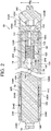
- the ram structure 12, see Fig. 2 is associated with the cylinder structure 14 and is capable of extending out from the cylinder structure 14 when pressurized hydraulic fluid is provided to the cylinder structure 14.
- Third and fourth pulleys 140 and 142 are coupled to an upper end of the ram structure 12, see Fig. 1 .
- One or a pair of lift chains (not shown) are fixed at one end to the cylinder structure 14, extend over the third pulley 140 and are coupled to a lower portion (not shown) of the fork carriage apparatus.
- pressurized fluid is provided to the cylinder structure 14, its ram structure 12 is extended causing the pulley 140 to move vertically relative to the third weldment 226. Vertical movement of the pulley 140 causes the lift chains to raise the fork carriage assembly relative to the third weldment 226.
- the cylinder structure 14, in the illustrated embodiment, comprises a cylinder tube 240, a cylinder base 242 and a cylinder cap 244, see Fig. 2 .
- the cylinder base 242 is coupled to the cylinder tube 240 via one or more welds or threads.
- the cylinder cap 244 is coupled to an outer end 240A of the cylinder tube 240 via threads.
- O-rings 244B and 244C are provided between the cylinder cap 244 and cylinder tube 240 to prevent fluid leakage.
- a ram element seal 244D is provided in an annular groove in the cylinder cap 244 and functions to prevent fluid from passing between the cylinder cap 244 and the ram structure 12 out of a cylinder structure outer open end 14A.
- the cap 244 and the tube 240 define a cylinder structure bore 246 extending from the base 242 to the outer open end 14A of the cylinder structure 14.
- the ram structure 12 is slidably mounted within the cylinder structure bore 246 and defines with the cylinder structure 14 a gap 60 therebetween.
- the cylinder base 242 is provided with first and second bores 242A and 242B, wherein the first bore 242A contains a flow control valve 242C, which limits the lowering speed of the fork carriage apparatus should hydraulic fluid pressure drop substantially at an entrance 242D of the first bore 242A, see Fig. 2 .
- Hydraulic fluid enters the cylinder structure 14 through the first bore entrance 242D in the cylinder base 242. In the illustrated embodiment, hydraulic fluid only enters the cylinder structure 14 through the cylinder base 242.
- the ram structure 12 may comprise a ram element 120 and a ram piston 122 coupled to a base 120B of the ram element 120 via threads.
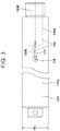
- the ram element 120 may have a first outer diameter OD 1 and the piston 122 may have a second outer diameter OD 2 greater than the first outer diameter OD 1 , see Figs. 2 and 3 .
- a piston seal 122A is provided in an annular recess of the piston 122.
- the ram element 120 comprises fluid passage structure 124 for defining a path for fluid to move internally through the ram structure 12.
- the fluid passage structure 124 comprises an axially extending bore 126 and a radially extending bore 136.
- the axially extending bore 126 communicates with the cylinder base second bore 242B so as to receive hydraulic fluid from the cylinder base 242, see Fig. 2 .
- the axially extending bore 126 comprises first and second sections 126A and 126B, wherein the first section 126A has a larger diameter than the second section 126B.
- a shutoff piston 128, a compression spring 130 and a retaining ring 132 are provided in the axially extending bore first section 126A.
- the piston 128 and spring 130 function to reduce fluid flow out of the cylinder tube 240 during descent of the ram structure 12 to reduce the velocity of the downwardly moving ram structure 12 once the piston 128 engages the cylinder base 242.
- fluid flow exits the cylinder tube 240 via a second bore 128B then a first bore 128A in the piston 128, see Fig. 2 .
- the ram structure 12 defines with the cylinder structure 14 the gap 60 therebetween.
- the gap 60 in the illustrated embodiment, comprises a first section 60A generally defined radially by a sidewall 120A of the ram element 120 of the ram structure 12 and an inner surface of the cylinder tube 240 and extends axially between the ram piston 122 and a first end 244A of the cylinder cap 244.
- the length of the gap first section 60A is variable based on the position of the ram piston 122 relative to the cylinder cap first end 244A.
- a second section 60B of the gap 60 is defined radially by the sidewall 120A of the ram element 120 and an inner surface of the cylinder cap 244 and extends axially from the first end 244A of the cylinder cap 244 to the ram element seal 244D.
- an inner diameter of the cylinder cap 244 is smaller than an inner diameter of the cylinder tube 240 such that the first section 60A of the gap 60 is radially larger than a second section 60B of the gap 60.
- the radially extending bore 136 in the ram element 120 communicates with the axially extending bore 126 and an outlet 138 in the sidewall 120A of the ram element 120, see Figs. 2 and 3 .
- An orifice or recess 139 is provided in the ram structure sidewall 120A and communicates with the outlet 138.
- the orifice 139 extends away from the outlet 138 in a direction towards the cylinder base 242. In the illustrated embodiment, the orifice 139 provides a path for fluid to flow from the first section 60A of the gap 60 to the outlet 138 and radially extending bore 136.
- the orifice 139 is shaped and sized such that the resistance to fluid flow from the gap first section 60A into the outlet 138 increases as the outlet 138 moves adjacent to and beyond the cylinder cap first end 244A and the cushioning seal 50 during ram structure extension causing pressure to gradually increase in the gap first section 60A resulting in the ram structure 12 decelerating at a substantially smooth rate at the end of ram structure extension.
- the increase in pressure in the gap first section 60A causes an increase in force being applied by the fluid against the ram piston 122 in a direction opposing ram structure extension.
- the orifice 139 is tear-drop shaped.
- the orifice 139 may have any another configuration, e.g., comprise multiple orifices, multiple slots of varying lengths or a single orifice of any geometric shape, such that the resistance to fluid flow from the gap first section 60A into the outlet 138 increases as the outlet 138 moves adjacent to and beyond the cylinder cap first end 244A and the cushioning seal 50.
- a hydraulic fluid supply source (not shown) provides fluid to the cylinder base 242 to increase the pressure of the fluid supplied to the base 242 in response to the increase in resistance to upward movement of the ram structure 12. Since the first and second secondary ram and cylinder assemblies 200 and 210 are connected to the same fluid supply source as the primary ram and cylinder assembly 10, the rams of the secondary assemblies also experience the increase in pressure and, hence, the rams of the first and second secondary ram and cylinder assemblies 200 and 210 begin to move vertically at a gradually increasing rate as the ram structure 12 decelerates.
- the cushioning seal 50 comprise a main body 52 having an axially and radially extending stepped slot 54 defining a separation in the main body 52 so as to allow the seal to expand outwardly, see Figs. 4-6 .
- the seal main body 52 has an unexpanded inner diameter ID which is slightly smaller than an outer diameter OD 1 of the ram element 120 such that the seal 50 is expanded slightly to be fitted over the ram element 120, see Figs. 3 and 4 .
- the seal 50 may be made from a metal, such as cast grey iron.
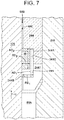
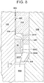
- the cap 244 may comprise an internal recess 245 for receiving the cushioning seal 50, see Figs. 7-9 (the seal 50 is not shown in Fig. 9 ).
- the recess 245 may have an axial dimension AD 1 greater than an axial dimension AD 2 of the seal 50 and a radial dimension RD 1 greater than a radial dimension RD 2 of the seal 50, see Fig. 7 .
- the seal 50 is movable within the recess 245 in a direction toward or away from the cylinder structure outer open end 14A.
- the cap 244 comprises a first end 244A.
- the cap 244 also comprises a second end 244E, which defines the cylinder structure outer open end 14A.
- the cap first end 244A comprise a plurality of grooves 244F through which hydraulic fluid passes into the gap first section 60A during ram structure retraction when the outlet 138 is in a gap first portion 60C.
- the gap first portion 60C extends from the cushioning seal 50 toward the cylinder structure outer open end 14A. More specifically, the gap first portion 60C extends from the seal 50 to the ram element seal 244D.
- the seal 50 is located between the ram element 120 and the cap 244, see Figs. 7 , 8 and 10 . Because the seal main body 52 must be slightly expanded to be positioned over the ram element 120, during ram structure extension and retraction, the seal 50 may move with the ram element 120 until it engages either an upper surface 344A or a lower surface 344B within the cap 244 and defining the cap recess 245 with a side surface 344C. During ram structure extension, the seal 50 moves upward in the same direction of movement as the ram structure 12, see arrow U in Fig. 7 , until the seal 50 engages the upper surface 344A of the cap recess 245 and a portion of the ram element outer surface 120A, see Fig.
- Lowering of the ram structure 12 is enhanced since a pressure of less than 0 gauge pressure is unlikely to occur within the gap first section 60A during ram structure retraction with the outlet 138 located above the cushioning seal 50; hence, a very low pressure, e.g., 0 gauge or less, is not applying a significant force to the ram structure 12 in a direction opposite to its downward direction of movement.
- the cushioning seal 150 comprises a main body 152 including an inner sidewall 154 and an angled outer sidewall 156, see Fig. 11 .
- the angled outer sidewall 156 defines an angle ⁇ 1 relative to horizontal falling within a range of from about 50 degrees to about 70 degrees and preferably about 60 degrees.
- the seal main body 152 may further comprise at least one groove or notch 158, three grooves 158 are provided in the illustrated embodiment, through which fluid passes into the gap first section 60A during ram structure retraction when the outlet 138 is in the gap first portion 60C.
- the seal 150 may be formed from a polymeric material, such as polytetrafluoroethylene (PTFE) or nylon or a combination of these materials.
- PTFE polytetrafluoroethylene
- the cylinder cap 444 comprises first and second ends 444A and 444B.
- the second end 444B defines the cylinder structure outer open end 14A.
- the first end 444A comprises an angled inner surface 444C defining an angle ⁇ 2 relative to vertical falling within a range of from about 20 degrees to about 40 degrees and preferably about 30 degrees. It is noted that an O-ring 244C is provided between the cylinder cap 444 and cylinder tube 440 to prevent fluid leakage.
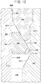
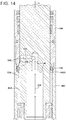
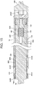
- the seal 150 is located between the ram element 120 and the cap 444 and cylinder tube 440, see Figs. 12-15 .
- An inner diameter of the seal 150 may be slightly larger than the outer diameter OD 1 of the ram element 120.
- the seal 150 is caused to move upward by fluid flowing through the gap first section 60A in the same direction of movement as the ram structure 12, see arrow U in Fig. 12 , until the seal 150 engages the angled inner surface 444C of the cylinder cap 444 and a portion of the ram element outer surface 120A, see Fig. 12 , so as to substantially seal or close off fluid flow into the gap first portion 60C.
- fluid flowing downward through the gap first portion 60C causes the seal 150 to move downward in the same direction of movement as the ram element 120, see arrow D in Fig. 13 , until an outer peripheral edge 159 of the seal 150 engages an angled surface 440A of the cylinder tube 440, see Fig. 13 .
Landscapes
- Engineering & Computer Science (AREA)
- Mechanical Engineering (AREA)
- General Engineering & Computer Science (AREA)
- Structural Engineering (AREA)
- Transportation (AREA)
- Fluid Mechanics (AREA)
- Physics & Mathematics (AREA)
- Chemical & Material Sciences (AREA)
- Combustion & Propulsion (AREA)
- Civil Engineering (AREA)
- Life Sciences & Earth Sciences (AREA)
- Geology (AREA)
- Actuator (AREA)
- Forklifts And Lifting Vehicles (AREA)
Claims (15)
- Aktuator in einem Gabelstapler mit einem ausfahrbaren Mast, wobei der Aktuator Folgendes umfasst:eine Zylinderkonstruktion (14) umfassend ein Zylinderrohr (240, 440), eine Zylinderbasis (242) und eine Zylinderkappe (244, 444), wobei die Basis (242) und die Kappe (244, 444) mit dem Rohr (240, 440) gekoppelt sind und das Rohr und die Kappe eine Zylinderkonstruktionsbohrung (246) definieren, die sich von der Basis (242) zu einem äußeren offenen Ende (14A) der Zylinderkonstruktion (14) erstreckt;eine Kolbenkonstruktion (12), die verschiebbar in der Zylinderkonstruktionsbohrung (246) angebracht ist und mit der Zylinderkonstruktion einen Spalt (60) zwischen diesen definiert, wobei die Kolbenkonstruktion (12) eine Fluiddurchgangskonstruktion (124) zum Definieren eines Wegs für die Bewegung des Fluids innen durch die Kolbenkonstruktion (12) hindurch aufweist, wobei der Weg mit einem Auslass (138) in einer Seitenwand (120A) der Kolbenkonstruktion (12) in Verbindung steht; undeine Dämpfungsdichtung (50, 150), die zwischen der Kolbenkonstruktion (12) und der Zylinderkonstruktion (14) angeordnet ist und mit der Kolbenkonstruktion (12) und der Zylinderkappe (244, 444) während des Ausfahrens der Kolbenstruktur in Eingriff steht, so dass die Dichtung (50, 150) im Wesentlichen einen ersten Abschnitt (60C) des Spalts (60) abschließt, der sich von der Dichtung (50, 150) zum äußeren offenen Ende (14A) der Zylinderkonstruktion erstreckt;dadurch gekennzeichnet, dass die Dämpfungsdichtung während des Einfahrens der Kolbenkonstruktion in einer Richtung des Einfahrens der Kolbenkonstruktion bewegt wird, so dass Fluid, das aus dem Seitenwandauslass (138) der Kolbenkonstruktion fließt, wenn der Auslass (138) sich in dem ersten Abschnitt (60C) des Spaltes befindet, zwischen der Dichtung (50, 150) und der Kappe (244, 444) strömt.
- Aktuator nach Anspruch 1, wobei die Kappe (244, 444) eine Innenausnehmung (245) für die Aufnahme der Dämpfungsdichtung (50, 150) umfasst, wobei die Ausnehmung (245) eine axiale Abmessung (AD1) aufweist, die größer als eine axiale Abmessung (AD2) der Dichtung (50, 150) ist, und eine radiale Abmessung (RD1), die größer als eine radiale Abmessung (RD2) der Dichtung ist, wobei die Dichtung (50, 150) in der Ausnehmung (245) in einer Richtung zu dem äußeren offenen Ende (14A) der Zylinderkonstruktion (14) oder von dieser weg bewegbar ist.
- Aktuator nach Anspruch 2, wobei die Dichtung (50, 150) einen Hauptkörper (52, 152) mit einem sich axial erstreckenden gestuften Schlitz (54) umfasst, um so zu ermöglichen, dass sich die Dichtung (50, 150) nach außen ausdehnt, wobei der Dichtungshauptkörper (52, 152) einen nicht ausgedehnten Innendurchmesser (ID) aufweist, der etwas kleiner als ein Außendurchmesser (OD1) der Kolbenkonstruktion (12) ist, so dass die Dichtung (50, 150) geringfügig ausgedehnt wird, um über der Kolbenkonstruktion (12) angebracht zu werden; optional, wobei die Dichtung (50, 150) aus einem Metall gebildet ist.
- Aktuator nach Anspruch 3, wobei die Kappe (244, 444) ein erstes und zweites Ende (244A, 444A, 244E, 444B) umfasst, wobei das zweite Ende (244E, 44B) das äußere offene Ende (14A) der Zylinderkonstruktion definiert, wobei das erste Ende (244A) eine oder mehrere Nuten (244F) aufweist, durch die Fluid in einen ersten Abschnitt (60A) des Spaltes (60) gelangt, der im Allgemeinen durch ein Kolbenelement (120) der Kolbenkonstruktion (12) und das Zylinderrohr (240) während des Ausfahrens der Kolbenkonstruktion definiert ist, wenn sich der Auslass (138) in dem ersten Abschnitt (60C) des Spaltes befindet.
- Aktuator nach Anspruch 4, wobei ein Innendurchmesser der Zylinderkappe (244, 444) kleiner ist als ein Innendurchmesser des Zylinderrohrs (240, 440), so dass der erste Abschnitt (60A) des Spaltes (60), der durch das Kolbenelement (120) und das Zylinderrohr (240, 440) definiert ist, größer als ein zweiter Abschnitt (60B) des Spaltes (60) ist, der durch das Kolbenelement (120) und die Zylinderkappe (244, 444) definiert ist.
- Aktuator nach Anspruch 1, wobei die Zylinderkappe (244, 444) ein erstes und ein zweites Ende (244A, 444A, 244E, 444B) umfasst, wobei das zweite Ende (244E, 444B) das äußere offene Ende (14A) der Zylinderkonstruktion definiert, wobei das erste Ende eine abgewinkelte Innenfläche (444C) umfasst.
- Aktuator nach Anspruch 6, wobei die Dichtung (50, 150) einen Hauptkörper (52, 152) umfasst, der eine innere Seitenwand (154) und eine abgewinkelte äußere Seitenwand (156) umfasst, wobei die Dichtung (50, 150) während des Ausfahrens der Kolbenstruktur mit Fluid beaufschlagt wird, so dass die innere Seitenwand (154) des Dichtungshauptkörpers mit der Kolbenkonstruktion (12) in Eingriff gelangt und die abgewinkelte äußere Seitenwand (156) des Dichtungshauptkörpers mit der abgewinkelten Innenfläche (444C) des ersten Endes der Zylinderkappe (244, 444) derart in Eingriff steht, dass die Dichtung (50, 150) den ersten Abschnitt (60C) des Spaltes im Wesentlichen verschließt;
wahlweise wobei die Dichtung (50, 150) aus einem Polymermaterial hergestellt ist. - Aktuator nach Anspruch 7, wobei der Dichtungshauptkörper (52, 152) ferner mindestens eine Nut umfasst (158), durch die Flüssigkeit in einen ersten Abschnitt (60A) des Spaltes (60) gelangt, der durch ein Kolbenelement (120) der Kolbenkonstruktion (12) und das Zylinderrohr (240, 440) während des Einfahrens der Kolbenkonstruktion definiert ist, wenn sich der Auslass (138) in dem ersten Abschnitt (60C) des Spaltes befindet.
- Aktuator nach Anspruch 8, wobei ein Innendurchmesser der Zylinderkappe (244, 444) kleiner ist als ein Innendurchmesser des Zylinderrohres (240, 440), so dass der erste Abschnitt (60A) des Spaltes (60), der durch das Kolbenelement (120) und das Zylinderrohr (240, 440) definiert ist, größer als ein zweiter Abschnitt (60B) des Spaltes (60) ist, der durch das Kolbenelement (120) und die Zylinderkappe (244, 444) definiert ist.
- Aktuator nach Anspruch 1, wobei eine Öffnung (139) in der Seitenwand (120A) der Kolbenkonstruktion vorgesehen ist, die mit dem Auslass (138) in Verbindung steht, und sich vom Auslass (138) weg in Richtung der Zylinderbasis (242) erstreckt, wobei die Öffnung (139) einen Weg bereitstellt, damit Fluid von einem ersten Abschnitt (60A) des Spaltes (60) fließen kann, der durch ein Kolbenelement (120) der Kolbenkonstruktion (12) und das Zylinderrohr (240, 440) in dem Auslass (138) während des Ausfahrens der Kolbenkonstruktion definiert ist, wobei der Auslass (138) in dem Kolbenelement (120) vorgesehen ist.
- Aktuator nach Anspruch 10, wobei die Öffnung (139) so geformt ist, dass der Widerstand gegen Fluidströmung aus dem ersten Abschnitt des Spaltes (60A) in den Auslass (138) zunimmt, wenn der Auslass (138) sich benachbart von und über die Dichtung (50, 150) hinaus bewegt, so dass der Druck im ersten Abschnitt des Spaltes (60A) allmählich ansteigt, was dazu führt, dass sich die Kolbenkonstruktion (12) am Ende des Ausfahrens der Kolbenkonstruktion mit einer im Wesentlichen gleichmäßigen Geschwindigkeit verlangsamt; wahlweise, wobei die Öffnung (139) eine tropfenförmige Öffnung ist.
- Aktuator nach Anspruch 1, wobei die Kolbenkonstruktion (12) ein Kolbenelement (120) und einen Kolben (122) umfasst, der mit dem Kolbenelement (120) gekoppelt ist, wobei das Kolbenelement (120) einen ersten Außendurchmesser (OD1) und der Kolben (122) einen zweiten Außendurchmesser (OD2) umfasst, der größer als der erste Außendurchmesser ist.
- Aktuator nach Anspruch 12, wobei der Spalt (60) einen ersten Abschnitt (60A) umfasst, der im Allgemeinen radial durch das Kolbenelement (120) der Kolbenkonstruktion (12) definiert ist, wobei das Zylinderrohr (240, 440) sich axial zwischen dem Kolben (122) und einem ersten Ende (244A, 444A) der Zylinderkappe (244, 444) und einem zweiten Abschnitt (60B) des Spaltes (60) erstreckt, der im Allgemeinen radial durch das Kolbenelement (120) und die Zylinderkappe (244, 444) definiert ist, und sich axial von dem ersten Ende (244A, 444A) der Zylinderkappe (244, 444) zu einer Kolbenelementdichtung (244D) erstreckt.
- Aktuator nach Anspruch 1, wobei die Fluiddurchlasskonstruktion (124) eine sich axial erstreckende Bohrung (126) aufweist, die in einem Kolbenelement (120) der Kolbenkonstruktion (12) vorgesehen ist, die mit der Zylinderbasis (242) in Verbindung steht und eine sich radial erstreckende Bohrung (136) in dem Kolbenelement (120) aufweist, die mit der sich axial erstreckenden Bohrung (126) und dem Auslass (138) in Verbindung steht, wobei der Auslass (138) in einer Seitenwand (120A) des Kolbenelements (120) vorgesehen ist.
- Aktuator nach Anspruch 1, wobei Fluid nur durch die Zylinderbasis (242) in die Zylinderkonstruktion (14) eintritt.
Applications Claiming Priority (2)
| Application Number | Priority Date | Filing Date | Title |
|---|---|---|---|
| US14/463,697 US9926178B2 (en) | 2014-08-20 | 2014-08-20 | Actuator in a lift truck |
| PCT/US2015/045635 WO2016028742A1 (en) | 2014-08-20 | 2015-08-18 | Actuator in a lift truck |
Publications (2)
| Publication Number | Publication Date |
|---|---|
| EP3183202A1 EP3183202A1 (de) | 2017-06-28 |
| EP3183202B1 true EP3183202B1 (de) | 2019-04-17 |
Family
ID=54012304
Family Applications (1)
| Application Number | Title | Priority Date | Filing Date |
|---|---|---|---|
| EP15756754.6A Active EP3183202B1 (de) | 2014-08-20 | 2015-08-18 | Aktuator in einem gabelstapler |
Country Status (7)
| Country | Link |
|---|---|
| US (1) | US9926178B2 (de) |
| EP (1) | EP3183202B1 (de) |
| KR (1) | KR102384425B1 (de) |
| CN (1) | CN106660771B (de) |
| AU (1) | AU2015305656B2 (de) |
| BR (1) | BR112017001742A2 (de) |
| WO (1) | WO2016028742A1 (de) |
Families Citing this family (2)
| Publication number | Priority date | Publication date | Assignee | Title |
|---|---|---|---|---|
| US10202988B2 (en) * | 2016-06-17 | 2019-02-12 | Deere & Company | Cushion mechanism for a hydraulic cylinder |
| CN112983924B (zh) * | 2019-12-18 | 2022-05-13 | 比亚迪股份有限公司 | 柱塞缸及车辆 |
Family Cites Families (32)
| Publication number | Priority date | Publication date | Assignee | Title |
|---|---|---|---|---|
| US1141447A (en) * | 1914-12-29 | 1915-06-01 | Oscar Dellwitz | Rolling-machine. |
| US2443312A (en) | 1944-03-06 | 1948-06-15 | Hpm Dev Corp | Pressure cylinder |
| FR1356328A (fr) * | 1963-02-11 | 1964-03-27 | Westinghouse Freins & Signaux | Vérin à rappel pneumatique, notamment pour appareil percuteur |
| US3285616A (en) | 1964-04-14 | 1966-11-15 | Kingsley A Doutt | Cushion seal for piston and cylinder assemblies |
| US3401604A (en) | 1967-05-17 | 1968-09-17 | Ind Specialties Inc | Differential area gas cylinder |
| AU3481871A (de) * | 1970-10-02 | 1973-05-03 | Massey Ferguson Services Nv | |
| US3913460A (en) | 1972-08-10 | 1975-10-21 | Mosier Ind Inc | Impact damping means for fluid cylinders |
| US3974910A (en) * | 1975-02-28 | 1976-08-17 | Papai Imre F | Fluid cylinder decelerating means |
| FR2317532A1 (fr) | 1975-07-07 | 1977-02-04 | Gratzmuller Jean Louis | Verin hydraulique a amortisseur incorpore avec realimentation de la chambre d'amortissement |
| US4207802A (en) * | 1978-04-05 | 1980-06-17 | Homuth Kenneth C | Hydraulic cylinder with improved dashpot and porting |
| US4301714A (en) * | 1979-05-24 | 1981-11-24 | Ab Mecman | Damping device in pressurized fluid cylinders |
| US4296675A (en) * | 1979-07-16 | 1981-10-27 | Aeroquip Corporation | Cylinder cushion with contractable ring |
| US4447047A (en) * | 1981-01-14 | 1984-05-08 | Di-Dro Systems Inc. | Cylinder structure |
| JPS5917074A (ja) | 1982-07-16 | 1984-01-28 | Hitachi Constr Mach Co Ltd | ロジツク弁 |
| US4458717A (en) | 1983-03-14 | 1984-07-10 | Aeroquip Corporation | Cylinder cushion seal |
| US4638717A (en) | 1985-02-01 | 1987-01-27 | Flo-Tork, Inc. | Combination of cushion, adjuster and side ports in a single unit rotary actuator |
| CN1008201B (zh) * | 1985-02-28 | 1990-05-30 | 株式会社丰田自动织机制作所 | 具有缓冲流量控制阀装置的液压操作缸 |
| US4688775A (en) * | 1985-04-15 | 1987-08-25 | Teledyne Industries, Inc. | Self-lubricating die cylinder |
| JP2617954B2 (ja) * | 1987-10-29 | 1997-06-11 | 日本バルカー工業株式会社 | 圧力シリンダ用クッションパッキン |
| DE19501495C1 (de) | 1995-01-19 | 1995-11-23 | Daimler Benz Ag | Hydraulische Ventilsteuervorrichtung |
| DE29617922U1 (de) | 1996-10-15 | 1996-11-28 | Heilmeier & Weinlein Fabrik für Oel-Hydraulik GmbH & Co KG, 81673 München | Magnetbetätigtes Ablaßventil eines elektrohydraulischen Hubmoduls |
| JPH10122205A (ja) | 1996-10-21 | 1998-05-12 | Kayaba Ind Co Ltd | 油圧シリンダ |
| JPH11292499A (ja) * | 1998-04-10 | 1999-10-26 | Toyota Autom Loom Works Ltd | フォークリフトのリフトシリンダ及びマスト装置 |
| JP3496808B2 (ja) | 1998-08-03 | 2004-02-16 | 日本輸送機株式会社 | ラムシリンダ |
| US6557456B2 (en) | 2001-05-24 | 2003-05-06 | The Raymond Corporation | Cushioned actuator |
| EP1585909B1 (de) | 2003-01-03 | 2014-07-09 | Zimmer, Günther | Führungssystem mit pneumatischer verzögerungsvorrichtung |
| DE102004036424A1 (de) | 2004-07-27 | 2006-03-23 | Still Gmbh | Hydraulikzylinder mit Endlagendämpfung |
| EP2331448B1 (de) | 2008-09-12 | 2016-11-02 | Crown Equipment Corporation | Mono-hubgerüst für ein materialienhandhabungsfahrzeug |
| DE102008055542A1 (de) | 2008-12-17 | 2010-07-01 | Bühler Druckguss AG | Druckübersetzer mit integriertem Rückschlagventil |
| KR101161304B1 (ko) * | 2009-10-28 | 2012-07-04 | 볼보 컨스트럭션 이큅먼트 에이비 | 체크링을 포함하는 유압실린더 쿠션장치 |
| CN202073867U (zh) * | 2011-05-08 | 2011-12-14 | 龙工(上海)液压有限公司 | 多级叉车起升液压缸 |
| JP5429830B2 (ja) * | 2012-03-26 | 2014-02-26 | 株式会社伊丹精機 | リフトシリンダ及びそれを備えたフォークリフト |
-
2014
- 2014-08-20 US US14/463,697 patent/US9926178B2/en active Active
-
2015
- 2015-08-18 BR BR112017001742A patent/BR112017001742A2/pt not_active Application Discontinuation
- 2015-08-18 CN CN201580044105.XA patent/CN106660771B/zh active Active
- 2015-08-18 AU AU2015305656A patent/AU2015305656B2/en active Active
- 2015-08-18 EP EP15756754.6A patent/EP3183202B1/de active Active
- 2015-08-18 KR KR1020177001640A patent/KR102384425B1/ko active Active
- 2015-08-18 WO PCT/US2015/045635 patent/WO2016028742A1/en not_active Ceased
Non-Patent Citations (1)
| Title |
|---|
| None * |
Also Published As
| Publication number | Publication date |
|---|---|
| BR112017001742A2 (pt) | 2018-02-14 |
| CN106660771A (zh) | 2017-05-10 |
| AU2015305656B2 (en) | 2019-11-14 |
| CN106660771B (zh) | 2019-04-16 |
| KR102384425B1 (ko) | 2022-04-12 |
| US20160052759A1 (en) | 2016-02-25 |
| KR20170044084A (ko) | 2017-04-24 |
| EP3183202A1 (de) | 2017-06-28 |
| WO2016028742A1 (en) | 2016-02-25 |
| AU2015305656A1 (en) | 2017-01-19 |
| US9926178B2 (en) | 2018-03-27 |
Similar Documents
| Publication | Publication Date | Title |
|---|---|---|
| US10619693B2 (en) | Compensator device | |
| CA2387281C (en) | Cushioned actuator | |
| AU2015305656B2 (en) | Actuator in a lift truck | |
| KR101721792B1 (ko) | 유체압 실린더 | |
| US6422349B1 (en) | Hydrostatic displacement drive for lifting and lowering and holding loads, in particular for lifts | |
| NL8102140A (nl) | Hijswerk voor een patientenlift. | |
| JP5443038B2 (ja) | 液圧シリンダ | |
| US3805681A (en) | Lift cylinder assembly for lift truck mast and carriage | |
| DE10344245B4 (de) | Druckluftbalancer | |
| EP4293250B1 (de) | Pneumatisch-hydraulische einziehbare vorrichtung | |
| KR101848425B1 (ko) | 다단 실린더 | |
| US9850923B2 (en) | Fluid flow regulator | |
| US10900505B2 (en) | Line rupture safeguard for a hydraulic cylinder | |
| EP1621780A1 (de) | Hydraulikzylinder mit Endlagendämpfung | |
| JP2014126142A (ja) | 流体圧シリンダ | |
| WO2016001428A1 (en) | Telescopic hydraulic cylinder | |
| KR20210073484A (ko) | 다단 복동 공압 실린더 | |
| JP5841015B2 (ja) | 衝撃動工具 | |
| RO125762A2 (ro) | Manipulator manual de transport | |
| KR102087860B1 (ko) | 가스 실린더의 캔 구조물 | |
| KR101456292B1 (ko) | 이물질 유입 방지를 위한 가스 스프링 | |
| JPH0459600A (ja) | リフトシリンダのクッション機構 | |
| JP5444495B1 (ja) | 昇降装置 | |
| CN103447319B (zh) | 一种三工位大托辊装置 | |
| CN114084858A (zh) | 活塞组件和液压千斤顶 |
Legal Events
| Date | Code | Title | Description |
|---|---|---|---|
| STAA | Information on the status of an ep patent application or granted ep patent |
Free format text: STATUS: THE INTERNATIONAL PUBLICATION HAS BEEN MADE |
|
| PUAI | Public reference made under article 153(3) epc to a published international application that has entered the european phase |
Free format text: ORIGINAL CODE: 0009012 |
|
| STAA | Information on the status of an ep patent application or granted ep patent |
Free format text: STATUS: REQUEST FOR EXAMINATION WAS MADE |
|
| 17P | Request for examination filed |
Effective date: 20170116 |
|
| AK | Designated contracting states |
Kind code of ref document: A1 Designated state(s): AL AT BE BG CH CY CZ DE DK EE ES FI FR GB GR HR HU IE IS IT LI LT LU LV MC MK MT NL NO PL PT RO RS SE SI SK SM TR |
|
| AX | Request for extension of the european patent |
Extension state: BA ME |
|
| DAV | Request for validation of the european patent (deleted) | ||
| DAX | Request for extension of the european patent (deleted) | ||
| RIC1 | Information provided on ipc code assigned before grant |
Ipc: F16J 15/16 20060101ALI20180912BHEP Ipc: F15B 15/22 20060101ALI20180912BHEP Ipc: F15B 15/14 20060101ALI20180912BHEP Ipc: B66F 9/22 20060101AFI20180912BHEP |
|
| GRAP | Despatch of communication of intention to grant a patent |
Free format text: ORIGINAL CODE: EPIDOSNIGR1 |
|
| STAA | Information on the status of an ep patent application or granted ep patent |
Free format text: STATUS: GRANT OF PATENT IS INTENDED |
|
| INTG | Intention to grant announced |
Effective date: 20181025 |
|
| GRAS | Grant fee paid |
Free format text: ORIGINAL CODE: EPIDOSNIGR3 |
|
| GRAA | (expected) grant |
Free format text: ORIGINAL CODE: 0009210 |
|
| STAA | Information on the status of an ep patent application or granted ep patent |
Free format text: STATUS: THE PATENT HAS BEEN GRANTED |
|
| AK | Designated contracting states |
Kind code of ref document: B1 Designated state(s): AL AT BE BG CH CY CZ DE DK EE ES FI FR GB GR HR HU IE IS IT LI LT LU LV MC MK MT NL NO PL PT RO RS SE SI SK SM TR |
|
| REG | Reference to a national code |
Ref country code: GB Ref legal event code: FG4D |
|
| REG | Reference to a national code |
Ref country code: CH Ref legal event code: EP |
|
| REG | Reference to a national code |
Ref country code: DE Ref legal event code: R096 Ref document number: 602015028505 Country of ref document: DE |
|
| REG | Reference to a national code |
Ref country code: AT Ref legal event code: REF Ref document number: 1121329 Country of ref document: AT Kind code of ref document: T Effective date: 20190515 Ref country code: IE Ref legal event code: FG4D |
|
| REG | Reference to a national code |
Ref country code: NL Ref legal event code: MP Effective date: 20190417 |
|
| REG | Reference to a national code |
Ref country code: LT Ref legal event code: MG4D |
|
| PG25 | Lapsed in a contracting state [announced via postgrant information from national office to epo] |
Ref country code: NL Free format text: LAPSE BECAUSE OF FAILURE TO SUBMIT A TRANSLATION OF THE DESCRIPTION OR TO PAY THE FEE WITHIN THE PRESCRIBED TIME-LIMIT Effective date: 20190417 |
|
| PG25 | Lapsed in a contracting state [announced via postgrant information from national office to epo] |
Ref country code: HR Free format text: LAPSE BECAUSE OF FAILURE TO SUBMIT A TRANSLATION OF THE DESCRIPTION OR TO PAY THE FEE WITHIN THE PRESCRIBED TIME-LIMIT Effective date: 20190417 Ref country code: LT Free format text: LAPSE BECAUSE OF FAILURE TO SUBMIT A TRANSLATION OF THE DESCRIPTION OR TO PAY THE FEE WITHIN THE PRESCRIBED TIME-LIMIT Effective date: 20190417 Ref country code: NO Free format text: LAPSE BECAUSE OF FAILURE TO SUBMIT A TRANSLATION OF THE DESCRIPTION OR TO PAY THE FEE WITHIN THE PRESCRIBED TIME-LIMIT Effective date: 20190717 Ref country code: SE Free format text: LAPSE BECAUSE OF FAILURE TO SUBMIT A TRANSLATION OF THE DESCRIPTION OR TO PAY THE FEE WITHIN THE PRESCRIBED TIME-LIMIT Effective date: 20190417 Ref country code: FI Free format text: LAPSE BECAUSE OF FAILURE TO SUBMIT A TRANSLATION OF THE DESCRIPTION OR TO PAY THE FEE WITHIN THE PRESCRIBED TIME-LIMIT Effective date: 20190417 Ref country code: PT Free format text: LAPSE BECAUSE OF FAILURE TO SUBMIT A TRANSLATION OF THE DESCRIPTION OR TO PAY THE FEE WITHIN THE PRESCRIBED TIME-LIMIT Effective date: 20190817 Ref country code: AL Free format text: LAPSE BECAUSE OF FAILURE TO SUBMIT A TRANSLATION OF THE DESCRIPTION OR TO PAY THE FEE WITHIN THE PRESCRIBED TIME-LIMIT Effective date: 20190417 Ref country code: ES Free format text: LAPSE BECAUSE OF FAILURE TO SUBMIT A TRANSLATION OF THE DESCRIPTION OR TO PAY THE FEE WITHIN THE PRESCRIBED TIME-LIMIT Effective date: 20190417 |
|
| PG25 | Lapsed in a contracting state [announced via postgrant information from national office to epo] |
Ref country code: BG Free format text: LAPSE BECAUSE OF FAILURE TO SUBMIT A TRANSLATION OF THE DESCRIPTION OR TO PAY THE FEE WITHIN THE PRESCRIBED TIME-LIMIT Effective date: 20190717 Ref country code: GR Free format text: LAPSE BECAUSE OF FAILURE TO SUBMIT A TRANSLATION OF THE DESCRIPTION OR TO PAY THE FEE WITHIN THE PRESCRIBED TIME-LIMIT Effective date: 20190718 Ref country code: LV Free format text: LAPSE BECAUSE OF FAILURE TO SUBMIT A TRANSLATION OF THE DESCRIPTION OR TO PAY THE FEE WITHIN THE PRESCRIBED TIME-LIMIT Effective date: 20190417 Ref country code: PL Free format text: LAPSE BECAUSE OF FAILURE TO SUBMIT A TRANSLATION OF THE DESCRIPTION OR TO PAY THE FEE WITHIN THE PRESCRIBED TIME-LIMIT Effective date: 20190417 Ref country code: RS Free format text: LAPSE BECAUSE OF FAILURE TO SUBMIT A TRANSLATION OF THE DESCRIPTION OR TO PAY THE FEE WITHIN THE PRESCRIBED TIME-LIMIT Effective date: 20190417 |
|
| REG | Reference to a national code |
Ref country code: AT Ref legal event code: MK05 Ref document number: 1121329 Country of ref document: AT Kind code of ref document: T Effective date: 20190417 |
|
| PG25 | Lapsed in a contracting state [announced via postgrant information from national office to epo] |
Ref country code: IS Free format text: LAPSE BECAUSE OF FAILURE TO SUBMIT A TRANSLATION OF THE DESCRIPTION OR TO PAY THE FEE WITHIN THE PRESCRIBED TIME-LIMIT Effective date: 20190817 |
|
| REG | Reference to a national code |
Ref country code: DE Ref legal event code: R097 Ref document number: 602015028505 Country of ref document: DE |
|
| PG25 | Lapsed in a contracting state [announced via postgrant information from national office to epo] |
Ref country code: EE Free format text: LAPSE BECAUSE OF FAILURE TO SUBMIT A TRANSLATION OF THE DESCRIPTION OR TO PAY THE FEE WITHIN THE PRESCRIBED TIME-LIMIT Effective date: 20190417 Ref country code: DK Free format text: LAPSE BECAUSE OF FAILURE TO SUBMIT A TRANSLATION OF THE DESCRIPTION OR TO PAY THE FEE WITHIN THE PRESCRIBED TIME-LIMIT Effective date: 20190417 Ref country code: RO Free format text: LAPSE BECAUSE OF FAILURE TO SUBMIT A TRANSLATION OF THE DESCRIPTION OR TO PAY THE FEE WITHIN THE PRESCRIBED TIME-LIMIT Effective date: 20190417 Ref country code: CZ Free format text: LAPSE BECAUSE OF FAILURE TO SUBMIT A TRANSLATION OF THE DESCRIPTION OR TO PAY THE FEE WITHIN THE PRESCRIBED TIME-LIMIT Effective date: 20190417 Ref country code: AT Free format text: LAPSE BECAUSE OF FAILURE TO SUBMIT A TRANSLATION OF THE DESCRIPTION OR TO PAY THE FEE WITHIN THE PRESCRIBED TIME-LIMIT Effective date: 20190417 Ref country code: SK Free format text: LAPSE BECAUSE OF FAILURE TO SUBMIT A TRANSLATION OF THE DESCRIPTION OR TO PAY THE FEE WITHIN THE PRESCRIBED TIME-LIMIT Effective date: 20190417 |
|
| PLBE | No opposition filed within time limit |
Free format text: ORIGINAL CODE: 0009261 |
|
| STAA | Information on the status of an ep patent application or granted ep patent |
Free format text: STATUS: NO OPPOSITION FILED WITHIN TIME LIMIT |
|
| PG25 | Lapsed in a contracting state [announced via postgrant information from national office to epo] |
Ref country code: SM Free format text: LAPSE BECAUSE OF FAILURE TO SUBMIT A TRANSLATION OF THE DESCRIPTION OR TO PAY THE FEE WITHIN THE PRESCRIBED TIME-LIMIT Effective date: 20190417 Ref country code: IT Free format text: LAPSE BECAUSE OF FAILURE TO SUBMIT A TRANSLATION OF THE DESCRIPTION OR TO PAY THE FEE WITHIN THE PRESCRIBED TIME-LIMIT Effective date: 20190417 |
|
| 26N | No opposition filed |
Effective date: 20200120 |
|
| PG25 | Lapsed in a contracting state [announced via postgrant information from national office to epo] |
Ref country code: TR Free format text: LAPSE BECAUSE OF FAILURE TO SUBMIT A TRANSLATION OF THE DESCRIPTION OR TO PAY THE FEE WITHIN THE PRESCRIBED TIME-LIMIT Effective date: 20190417 |
|
| PG25 | Lapsed in a contracting state [announced via postgrant information from national office to epo] |
Ref country code: CH Free format text: LAPSE BECAUSE OF NON-PAYMENT OF DUE FEES Effective date: 20190831 Ref country code: LU Free format text: LAPSE BECAUSE OF NON-PAYMENT OF DUE FEES Effective date: 20190818 Ref country code: SI Free format text: LAPSE BECAUSE OF FAILURE TO SUBMIT A TRANSLATION OF THE DESCRIPTION OR TO PAY THE FEE WITHIN THE PRESCRIBED TIME-LIMIT Effective date: 20190417 Ref country code: LI Free format text: LAPSE BECAUSE OF NON-PAYMENT OF DUE FEES Effective date: 20190831 Ref country code: MC Free format text: LAPSE BECAUSE OF FAILURE TO SUBMIT A TRANSLATION OF THE DESCRIPTION OR TO PAY THE FEE WITHIN THE PRESCRIBED TIME-LIMIT Effective date: 20190417 |
|
| REG | Reference to a national code |
Ref country code: BE Ref legal event code: MM Effective date: 20190831 |
|
| PG25 | Lapsed in a contracting state [announced via postgrant information from national office to epo] |
Ref country code: IE Free format text: LAPSE BECAUSE OF NON-PAYMENT OF DUE FEES Effective date: 20190818 |
|
| PG25 | Lapsed in a contracting state [announced via postgrant information from national office to epo] |
Ref country code: BE Free format text: LAPSE BECAUSE OF NON-PAYMENT OF DUE FEES Effective date: 20190831 |
|
| PG25 | Lapsed in a contracting state [announced via postgrant information from national office to epo] |
Ref country code: CY Free format text: LAPSE BECAUSE OF FAILURE TO SUBMIT A TRANSLATION OF THE DESCRIPTION OR TO PAY THE FEE WITHIN THE PRESCRIBED TIME-LIMIT Effective date: 20190417 |
|
| PG25 | Lapsed in a contracting state [announced via postgrant information from national office to epo] |
Ref country code: MT Free format text: LAPSE BECAUSE OF FAILURE TO SUBMIT A TRANSLATION OF THE DESCRIPTION OR TO PAY THE FEE WITHIN THE PRESCRIBED TIME-LIMIT Effective date: 20190417 Ref country code: HU Free format text: LAPSE BECAUSE OF FAILURE TO SUBMIT A TRANSLATION OF THE DESCRIPTION OR TO PAY THE FEE WITHIN THE PRESCRIBED TIME-LIMIT; INVALID AB INITIO Effective date: 20150818 |
|
| PG25 | Lapsed in a contracting state [announced via postgrant information from national office to epo] |
Ref country code: MK Free format text: LAPSE BECAUSE OF FAILURE TO SUBMIT A TRANSLATION OF THE DESCRIPTION OR TO PAY THE FEE WITHIN THE PRESCRIBED TIME-LIMIT Effective date: 20190417 |
|
| P01 | Opt-out of the competence of the unified patent court (upc) registered |
Effective date: 20230529 |
|
| PGFP | Annual fee paid to national office [announced via postgrant information from national office to epo] |
Ref country code: DE Payment date: 20250820 Year of fee payment: 11 |
|
| PGFP | Annual fee paid to national office [announced via postgrant information from national office to epo] |
Ref country code: GB Payment date: 20250820 Year of fee payment: 11 |
|
| PGFP | Annual fee paid to national office [announced via postgrant information from national office to epo] |
Ref country code: FR Payment date: 20250829 Year of fee payment: 11 |