EP4293250B1 - Pneumatisch-hydraulische einziehbare vorrichtung - Google Patents
Pneumatisch-hydraulische einziehbare vorrichtung Download PDFInfo
- Publication number
- EP4293250B1 EP4293250B1 EP23177678.2A EP23177678A EP4293250B1 EP 4293250 B1 EP4293250 B1 EP 4293250B1 EP 23177678 A EP23177678 A EP 23177678A EP 4293250 B1 EP4293250 B1 EP 4293250B1
- Authority
- EP
- European Patent Office
- Prior art keywords
- pressure relief
- piston rod
- retractable device
- pneumatic hydraulic
- relief element
- Prior art date
- Legal status (The legal status is an assumption and is not a legal conclusion. Google has not performed a legal analysis and makes no representation as to the accuracy of the status listed.)
- Active
Links
Images



Classifications
-
- F—MECHANICAL ENGINEERING; LIGHTING; HEATING; WEAPONS; BLASTING
- F16—ENGINEERING ELEMENTS AND UNITS; GENERAL MEASURES FOR PRODUCING AND MAINTAINING EFFECTIVE FUNCTIONING OF MACHINES OR INSTALLATIONS; THERMAL INSULATION IN GENERAL
- F16F—SPRINGS; SHOCK-ABSORBERS; MEANS FOR DAMPING VIBRATION
- F16F9/00—Springs, vibration-dampers, shock-absorbers, or similarly-constructed movement-dampers using a fluid or the equivalent as damping medium
- F16F9/02—Springs, vibration-dampers, shock-absorbers, or similarly-constructed movement-dampers using a fluid or the equivalent as damping medium using gas only or vacuum
- F16F9/0209—Telescopic
- F16F9/0245—Means for adjusting the length of, or for locking, the spring or dampers
- F16F9/0263—Means for adjusting the length of, or for locking, the spring or dampers characterised by actuation means, e.g. manually-operated lever arrangement
-
- F—MECHANICAL ENGINEERING; LIGHTING; HEATING; WEAPONS; BLASTING
- F15—FLUID-PRESSURE ACTUATORS; HYDRAULICS OR PNEUMATICS IN GENERAL
- F15B—SYSTEMS ACTING BY MEANS OF FLUIDS IN GENERAL; FLUID-PRESSURE ACTUATORS, e.g. SERVOMOTORS; DETAILS OF FLUID-PRESSURE SYSTEMS, NOT OTHERWISE PROVIDED FOR
- F15B15/00—Fluid-actuated devices for displacing a member from one position to another; Gearing associated therewith
- F15B15/08—Characterised by the construction of the motor unit
- F15B15/14—Characterised by the construction of the motor unit of the straight-cylinder type
- F15B15/16—Characterised by the construction of the motor unit of the straight-cylinder type of the telescopic type
-
- F—MECHANICAL ENGINEERING; LIGHTING; HEATING; WEAPONS; BLASTING
- F15—FLUID-PRESSURE ACTUATORS; HYDRAULICS OR PNEUMATICS IN GENERAL
- F15B—SYSTEMS ACTING BY MEANS OF FLUIDS IN GENERAL; FLUID-PRESSURE ACTUATORS, e.g. SERVOMOTORS; DETAILS OF FLUID-PRESSURE SYSTEMS, NOT OTHERWISE PROVIDED FOR
- F15B13/00—Details of servomotor systems ; Valves for servomotor systems
- F15B13/02—Fluid distribution or supply devices characterised by their adaptation to the control of servomotors
- F15B13/024—Pressure relief valves
-
- F—MECHANICAL ENGINEERING; LIGHTING; HEATING; WEAPONS; BLASTING
- F16—ENGINEERING ELEMENTS AND UNITS; GENERAL MEASURES FOR PRODUCING AND MAINTAINING EFFECTIVE FUNCTIONING OF MACHINES OR INSTALLATIONS; THERMAL INSULATION IN GENERAL
- F16F—SPRINGS; SHOCK-ABSORBERS; MEANS FOR DAMPING VIBRATION
- F16F9/00—Springs, vibration-dampers, shock-absorbers, or similarly-constructed movement-dampers using a fluid or the equivalent as damping medium
- F16F9/02—Springs, vibration-dampers, shock-absorbers, or similarly-constructed movement-dampers using a fluid or the equivalent as damping medium using gas only or vacuum
- F16F9/0209—Telescopic
- F16F9/0245—Means for adjusting the length of, or for locking, the spring or dampers
- F16F9/0272—Means for adjusting the length of, or for locking, the spring or dampers with control rod extending through the piston rod into the piston
-
- F—MECHANICAL ENGINEERING; LIGHTING; HEATING; WEAPONS; BLASTING
- F16—ENGINEERING ELEMENTS AND UNITS; GENERAL MEASURES FOR PRODUCING AND MAINTAINING EFFECTIVE FUNCTIONING OF MACHINES OR INSTALLATIONS; THERMAL INSULATION IN GENERAL
- F16F—SPRINGS; SHOCK-ABSORBERS; MEANS FOR DAMPING VIBRATION
- F16F9/00—Springs, vibration-dampers, shock-absorbers, or similarly-constructed movement-dampers using a fluid or the equivalent as damping medium
- F16F9/32—Details
- F16F9/56—Means for adjusting the length of, or for locking, the spring or damper, e.g. at the end of the stroke
Definitions
- the present invention relates to retractable devices and more particularly, to a pneumatic hydraulic retractable device.
- a pneumatic height adjustment structure disclosed by TW M619009 uses a control set to push a shaft upwards for driving a valve door to move upwards. This allows the first air chamber and the second air chamber to communicate with each other. Under pressure of saddle, the lifting tube is lowered to adjust height of the saddle. If the lifting tube is not pressured, the lifting tube is driven by the air flowing from the second air chamber to the first air chamber to rise, thereby adjusting height of the saddle.
- the airtight effect is generated between the piston valve and the shock-absorbing element so as to cause greater resistance therebetween.
- the rider needs to apply more force to push the saddle down, such that it is very inconvenient for the rider to operate.
- the airtight effect will counteract the shock-absorbing effect produced by the air, and therefore the proper shock- absorbing effect cannot be exerted.
- the pneumatic hydraulic retractable device of the present invention comprises a fluid pressure cylinder, a piston rod, a control valve set, and a pressure relief element.
- the fluid pressure cylinder has a cylinder body and a plug seat disposed in the cylinder body and located at one end of the cylinder body.
- the piston rod is movably disposed in the fluid pressure cylinder.
- the control valve set includes a valve seat disposed at one end of the piston rod and forms an upper fluid chamber and a lower fluid chamber with the cylinder body therebetween, and a valve rod disposed in the valve seat and moved between a close position where the upper and lower fluid chambers do not communicate with each other and an open position where the upper and lower fluid chambers communicate with each other.
- the pressure relief element is disposed between the valve seat and the plug seat and penetrated by the piston rod.
- the pressure relief element has a communication portion, and one end of the pressure relief element and the piston rod forms a pressure relief gap therebetween.
- the pressure relief gap communicates with the lower fluid chamber through the communication portion.
- the pressure relief element extends integrally from one end of the valve seat towards the plug seat.
- one end of the pressure relief element has an annular groove.
- a diameter of the annular groove is greater than a diameter of the piston rod so as to form the pressure relief gap between the annular groove and the piston rod.
- the pressure relief element has one end supporting one end of the valve seat and the other end abutted against the plug seat.
- an inner surface of the pressure relief element has a recess forming the pressure relief gap with the piston rod.
- the communication portion can be a plurality of notches arranged in an equally-spaced annular manner or a plurality of through holes arranged in an equally-spaced annular manner.
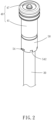
- a pneumatic hydraulic retractable device 10 of a first embodiment of the present invention comprises a fluid pressure cylinder 20, a piston rod 30, a control valve set 40, and a pressure relief element 50.
- the fluid pressure cylinder 20 includes a cylinder body 22, an end block 24 fixed to one end of the cylinder body 22, a buffer member 26 abutted against one end of the end block 24, and a plug seat 28 abutted against the other end of the buffer member 26.
- the piston rod 30 is movably disposed in the fluid pressure cylinder 20.
- the control valve set 40 includes a valve seat 41 and a valve rod 47.
- the valve seat 41 is disposed in the cylinder body 22 and connected to one end of the piston rod 30, such that the valve seat 41 can be moved together with the piston rod 30, and the valve seat 41 and the cylinder body 22 form an upper fluid chamber 45 and a lower fluid chamber 46.
- the valve seat 41 includes a valve hole 42 communicating with the upper fluid chamber 45, a plurality of inner radial holes 43 communicating with the valve hole 42, and a plurality of outer radial holes 44 communicating with the inner radial holes 43 and the lower fluid chamber 46.
- the valve rod 47 is disposed in the valve hole 42 of the valve seat 41 and has a bottom end thereof abutted against a push rod 48 located in the piston rod 30.
- valve rod 47 When the valve rod 47 is not pushed by the push rod 48, the valve rod 47 is held in a close position P1 as shown in FIG. 3 by a compression spring 49, such that the upper and lower fluid chambers 45, 46 do not communicate with each other.
- the valve rod 47 When the valve rod 47 is pushed by the push rod 48 to move to an open position P2 as shown in FIG. 4 , the upper and lower fluid chambers 45, 46 communicate with each other through the valve holes 42, the inner radial holes 43, and the outer radial holes 44.
- the pressure relief element 50 is disposed between the valve seat 41 and the plug seat 28 and penetrated by the piston rod 30.
- the pressure relief element 50 extends integrally from one end of the valve seat 41 towards the plug seat 28.
- the bottom end of the pressure relief element 50 has an annular groove 52.
- the diameter of the annular groove 52 is greater than the diameter of the piston rod 30 so as to form a pressure relief gap 56 between the annular groove 52 and the piston rod 30.
- the bottom end of the pressure relief element 50 has a communication portion 54.
- the pressure relief gap 56 communicates with the lower fluid chamber 46 through the communication portion 54.
- the communication portion 54 is formed by a plurality of notches 542 arranged in an equally-spaced manner around the annular groove 52.
- the valve rod 47 when the valve rod 47 is located at the open position P2 as shown in 4, the upper and lower fluid chambers 45, 46 communicate with other, such that fluid (such as hydraulic oil or high pressure gas) flows between the upper and lower fluid chambers 45, 46.
- fluid such as hydraulic oil or high pressure gas
- the fluid is allowed by the communication portion 54 formed by the notches 542 to flow between the lower fluid chamber 46 and the pressure relief gap 56 (as shown by the arrow in FIG. 4 ) for reducing airtight effect generated between the pressure relief element 50 and the plug seat 28 when the pressure relief element 50 is abutted against the plug seat 28.
- the piston rod 30 can be pressed by the rider conveniently, and on the other hand, the proper shock- absorbing effect can be exerted by the present invention.
- the communication portion 54 can be varied in structure. As shown in FIGS. 5 and 6 , in the second embodiment of the present invention, the communication portion 54 is formed by a plurality of through holes 544 arranged in an equally-spaced manner around the annular groove 52. In this way, the fluid is allowed by the through holes 544 to flow between the lower fluid chamber 46 and the pressure relief gap 56 (as shown by the arrow in FIG. 6 ) for reducing the airtight effect generated between the pressure relief element 50 and the plug seat 28 when the pressure relief element 50 is abutted against the plug seat 28.
- the pressure relief element 60 is not connected with the valve seat 41.
- the top end of the pressure relief element 60 supports the bottom end of the valve seat 41, and the bottom end of the pressure relief element 60 is abutted against the plug seat 28.
- the inner surface of the pressure relief element 60 has a plurality of recesses 62 (the number is not limited as long as at least one is sufficient) arranged in an equally-spaced annular manner.
- the recesses 62 extend straight from the top end of the pressure relief element 60 to the bottom end of the pressure relief element 60, such that a pressure relief gap 66 is formed by the piston rod 30 and each of the recesses 62.
- the bottom end of the pressure relief element 60 has a communication portion 64.
- the communication portion 64 is formed by a plurality of notches 642 arranged in an equally-spaced annular manner. In this way, when the valve rod 47 is located at the open position P2 as shown in FIG. 9 , the upper and lower fluid chambers 45, 46 communicate with other, such that the fluid (such as hydraulic oil or high pressure gas) flows between the upper and lower fluid chambers 45, 46. At this time, the fluid is allowed by the communication portion 64 formed by the notches 642 to flow between the lower fluid chamber 46 and the pressure relief gaps 66 (as shown by the arrow in FIG. 9 ) for achieving the purpose of reducing the airtight effect.
- the piston rod 30 can be pressed by the rider conveniently, and on the other hand, the proper shock-absorbing effect can be exerted by the present invention.
- the communication portion 64 can be varied in structure. As shown in FIGS. 10 and 11 , in the fourth embodiment of the present invention, the communication portion 64 is formed by a plurality of through holes 644 arranged in an equally-spaced annular manner. In this way, the fluid is allowed by the through holes 644 to flow between the lower fluid chamber 46 and the pressure relief gap 66 (as shown by the arrow in FIG. 11 ) for achieving the purpose of reducing the airtight effect.
Landscapes
- Engineering & Computer Science (AREA)
- General Engineering & Computer Science (AREA)
- Mechanical Engineering (AREA)
- Physics & Mathematics (AREA)
- Fluid Mechanics (AREA)
- Safety Valves (AREA)
- Fluid-Damping Devices (AREA)
- Forklifts And Lifting Vehicles (AREA)
- Actuator (AREA)
Claims (7)
- Pneumatisch-hydraulische Einziehvorrichtung (10), welche umfasst:einen Fluiddruckzylinder (20) mit einem Zylinderkörper (22) und einem Stecksitz (28), der in dem Zylinderkörper (22) angeordnet ist und sich an einem Ende des Zylinderkörpers (22) befindet;eine Kolbenstange (30), die beweglich in dem Fluiddruckzylinder (20) angeordnet ist;einen Steuerventilsatz (40) mit einem Ventilsitz (41), der an einem Ende der Kolbenstange (30) angeordnet ist und eine obere Fluidkammer (45) und eine untere Fluidkammer (46) mit dem Zylinderkörper (22) dazwischen bildet, und einer Ventilstange (47), die in dem Ventilsitz (41) angeordnet ist und zwischen einer geschlossenen Position (P1), in der die obere und die untere Fluidkammer (45, 46) nicht miteinander in Verbindung stehen, und einer offenen Position (P2), in der die obere und die untere Fluidkammer (45, 46) miteinander in Verbindung stehen, bewegt wird; undein Druckentlastungselement (50), das zwischen dem Ventilsitz (41) und dem Stecksitz (28) angeordnet ist und von der Kolbenstange (30) durchdrungen wird und einen Verbindungsabschnitt (54) aufweist, worin ein Ende des Druckentlastungselements (50) und die Kolbenstange (30) einen Druckentlastungsspalt (56) dazwischen ausbilden, der durch den Verbindungsabschnitt (54) mit der unteren Fluidkammer (46) in Verbindung steht.
- Pneumatisch-hydraulische Einziehvorrichtung (10) nach Anspruch 1, worin sich das Druckentlastungselement (50) einstückig von einem Ende des Ventilsitzes (41) in Richtung des Stecksitzes (28) erstreckt.
- Pneumatisch-hydraulische Einziehvorrichtung (10) nach Anspruch 2, worin ein Ende des Druckentlastungselements (50) eine Ringnut (52) aufweist; und ein Durchmesser der Ringnut (52) größer ist als ein Durchmesser der Kolbenstange (30), um den Druckentlastungsspalt (56) zwischen der Ringnut (52) und der Kolbenstange (30) auszubilden.
- Pneumatisch-hydraulische Einziehvorrichtung (10) nach Anspruch 1, worin das Druckentlastungselement (50) mit einem Ende ein Ende des Ventilsitzes (41) abstützt und mit dem anderen Ende an dem Stecksitz (28) anliegt.
- Pneumatisch-hydraulische Einziehvorrichtung (10) nach Anspruch 4, worin eine Innenfläche des Druckentlastungselements (50) eine Ausnehmung aufweist, die mit der Kolbenstange (30) den Druckentlastungsspalt (56) ausbildet.
- Pneumatisch-hydraulische Einziehvorrichtung (10) nach Anspruch 1, worin der Verbindungsabschnitt (54) durch mehrere ringförmig in gleichem Abstand angeordnete Kerben (542) ausgebildet ist.
- Pneumatisch-hydraulische Einziehvorrichtung (10) nach Anspruch 1, worin der Verbindungsabschnitt (54) durch mehrere ringförmig in gleichem Abstand angeordnete Durchgangslöcher ausgebildet ist.
Applications Claiming Priority (1)
| Application Number | Priority Date | Filing Date | Title |
|---|---|---|---|
| TW111206311U TWM634032U (zh) | 2022-06-15 | 2022-06-15 | 氣油壓式伸縮裝置 |
Publications (3)
| Publication Number | Publication Date |
|---|---|
| EP4293250A1 EP4293250A1 (de) | 2023-12-20 |
| EP4293250B1 true EP4293250B1 (de) | 2025-02-26 |
| EP4293250C0 EP4293250C0 (de) | 2025-02-26 |
Family
ID=85784477
Family Applications (1)
| Application Number | Title | Priority Date | Filing Date |
|---|---|---|---|
| EP23177678.2A Active EP4293250B1 (de) | 2022-06-15 | 2023-06-06 | Pneumatisch-hydraulische einziehbare vorrichtung |
Country Status (3)
| Country | Link |
|---|---|
| US (1) | US11933330B2 (de) |
| EP (1) | EP4293250B1 (de) |
| TW (1) | TWM634032U (de) |
Families Citing this family (1)
| Publication number | Priority date | Publication date | Assignee | Title |
|---|---|---|---|---|
| CN121474212B (zh) * | 2026-01-07 | 2026-03-17 | 浙江阿凡特液压科技有限公司 | 一种中段驱动油缸及其加工方法 |
Family Cites Families (5)
| Publication number | Priority date | Publication date | Assignee | Title |
|---|---|---|---|---|
| GB9325345D0 (en) * | 1993-12-10 | 1994-02-16 | Dev Enterprises Limited | Gas springs |
| US11306798B2 (en) * | 2008-05-09 | 2022-04-19 | Fox Factory, Inc. | Position sensitive suspension damping with an active valve |
| TWM404816U (en) * | 2010-09-01 | 2011-06-01 | Kind Shock Hi Tech Co Ltd | Structure improvement for rear shock absorber |
| JP5755793B1 (ja) * | 2014-05-12 | 2015-07-29 | 株式会社ショーワ | ピストンシリンダ装置 |
| TWM619009U (zh) | 2021-06-04 | 2021-11-01 | 凱薩克科技股份有限公司 | 自行車座墊管之氣壓式調整高度結構 |
-
2022
- 2022-06-15 TW TW111206311U patent/TWM634032U/zh unknown
-
2023
- 2023-06-06 EP EP23177678.2A patent/EP4293250B1/de active Active
- 2023-06-15 US US18/335,490 patent/US11933330B2/en active Active
Also Published As
| Publication number | Publication date |
|---|---|
| TWM634032U (zh) | 2022-11-11 |
| US11933330B2 (en) | 2024-03-19 |
| US20230407889A1 (en) | 2023-12-21 |
| EP4293250C0 (de) | 2025-02-26 |
| EP4293250A1 (de) | 2023-12-20 |
Similar Documents
| Publication | Publication Date | Title |
|---|---|---|
| KR102137287B1 (ko) | 감쇠력 조정식 완충기 | |
| CN103119322B (zh) | 可调节的减振器 | |
| JP5941359B2 (ja) | 緩衝器のバルブ構造 | |
| US9422783B2 (en) | Stabilized valve | |
| US9796232B2 (en) | Twin tube damper with remote gas reservoir | |
| JP6808837B2 (ja) | 緩衝器 | |
| EP3192727B1 (de) | Pneumatische und hydraulische hebesitzrohranordnung für fahrräder | |
| WO2018061726A1 (ja) | 減衰力調整式緩衝器 | |
| GB2266573A (en) | Variable damping force shock absorber | |
| JP2003166584A (ja) | 減衰力調整式油圧緩衝器 | |
| JP2009036336A (ja) | 流量制御弁 | |
| US11933330B2 (en) | Pneumatic hydraulic retractable device | |
| US20090115159A1 (en) | Arrangement for telescopic fork leg with parallel damping | |
| JP2011257002A (ja) | ショックアブソーバー | |
| GB2347479A (en) | Damper | |
| JP4453000B2 (ja) | 油圧緩衝器 | |
| US11572963B2 (en) | Pneumatic-hydraulic control valve | |
| JPWO2020149224A1 (ja) | 緩衝器 | |
| JPH07111125B2 (ja) | 蒸気加減弁 | |
| JP3996132B2 (ja) | 液圧シリンダのクッション装置 | |
| CN119844511A (zh) | 减振器和车辆 | |
| JP2010196798A (ja) | バルブ構造 | |
| CN217653138U (zh) | 气油压式伸缩装置 | |
| KR102716569B1 (ko) | 완충기 | |
| CN2498402Y (zh) | 带有活塞换向阻尼装置的油缸 |
Legal Events
| Date | Code | Title | Description |
|---|---|---|---|
| PUAI | Public reference made under article 153(3) epc to a published international application that has entered the european phase |
Free format text: ORIGINAL CODE: 0009012 |
|
| STAA | Information on the status of an ep patent application or granted ep patent |
Free format text: STATUS: REQUEST FOR EXAMINATION WAS MADE |
|
| 17P | Request for examination filed |
Effective date: 20230606 |
|
| AK | Designated contracting states |
Kind code of ref document: A1 Designated state(s): AL AT BE BG CH CY CZ DE DK EE ES FI FR GB GR HR HU IE IS IT LI LT LU LV MC ME MK MT NL NO PL PT RO RS SE SI SK SM TR |
|
| GRAP | Despatch of communication of intention to grant a patent |
Free format text: ORIGINAL CODE: EPIDOSNIGR1 |
|
| STAA | Information on the status of an ep patent application or granted ep patent |
Free format text: STATUS: GRANT OF PATENT IS INTENDED |
|
| INTG | Intention to grant announced |
Effective date: 20241016 |
|
| GRAS | Grant fee paid |
Free format text: ORIGINAL CODE: EPIDOSNIGR3 |
|
| GRAA | (expected) grant |
Free format text: ORIGINAL CODE: 0009210 |
|
| STAA | Information on the status of an ep patent application or granted ep patent |
Free format text: STATUS: THE PATENT HAS BEEN GRANTED |
|
| AK | Designated contracting states |
Kind code of ref document: B1 Designated state(s): AL AT BE BG CH CY CZ DE DK EE ES FI FR GB GR HR HU IE IS IT LI LT LU LV MC ME MK MT NL NO PL PT RO RS SE SI SK SM TR |
|
| REG | Reference to a national code |
Ref country code: GB Ref legal event code: FG4D |
|
| REG | Reference to a national code |
Ref country code: CH Ref legal event code: EP |
|
| REG | Reference to a national code |
Ref country code: DE Ref legal event code: R096 Ref document number: 602023002172 Country of ref document: DE |
|
| REG | Reference to a national code |
Ref country code: IE Ref legal event code: FG4D |
|
| U01 | Request for unitary effect filed |
Effective date: 20250317 |
|
| U07 | Unitary effect registered |
Designated state(s): AT BE BG DE DK EE FI FR IT LT LU LV MT NL PT RO SE SI Effective date: 20250328 |
|
| PG25 | Lapsed in a contracting state [announced via postgrant information from national office to epo] |
Ref country code: RS Free format text: LAPSE BECAUSE OF FAILURE TO SUBMIT A TRANSLATION OF THE DESCRIPTION OR TO PAY THE FEE WITHIN THE PRESCRIBED TIME-LIMIT Effective date: 20250526 |
|
| PG25 | Lapsed in a contracting state [announced via postgrant information from national office to epo] |
Ref country code: PL Free format text: LAPSE BECAUSE OF FAILURE TO SUBMIT A TRANSLATION OF THE DESCRIPTION OR TO PAY THE FEE WITHIN THE PRESCRIBED TIME-LIMIT Effective date: 20250226 |
|
| PG25 | Lapsed in a contracting state [announced via postgrant information from national office to epo] |
Ref country code: ES Free format text: LAPSE BECAUSE OF FAILURE TO SUBMIT A TRANSLATION OF THE DESCRIPTION OR TO PAY THE FEE WITHIN THE PRESCRIBED TIME-LIMIT Effective date: 20250226 |
|
| PG25 | Lapsed in a contracting state [announced via postgrant information from national office to epo] |
Ref country code: NO Free format text: LAPSE BECAUSE OF FAILURE TO SUBMIT A TRANSLATION OF THE DESCRIPTION OR TO PAY THE FEE WITHIN THE PRESCRIBED TIME-LIMIT Effective date: 20250526 Ref country code: IS Free format text: LAPSE BECAUSE OF FAILURE TO SUBMIT A TRANSLATION OF THE DESCRIPTION OR TO PAY THE FEE WITHIN THE PRESCRIBED TIME-LIMIT Effective date: 20250626 |
|
| PG25 | Lapsed in a contracting state [announced via postgrant information from national office to epo] |
Ref country code: HR Free format text: LAPSE BECAUSE OF FAILURE TO SUBMIT A TRANSLATION OF THE DESCRIPTION OR TO PAY THE FEE WITHIN THE PRESCRIBED TIME-LIMIT Effective date: 20250226 |
|
| PG25 | Lapsed in a contracting state [announced via postgrant information from national office to epo] |
Ref country code: GR Free format text: LAPSE BECAUSE OF FAILURE TO SUBMIT A TRANSLATION OF THE DESCRIPTION OR TO PAY THE FEE WITHIN THE PRESCRIBED TIME-LIMIT Effective date: 20250527 |
|
| U20 | Renewal fee for the european patent with unitary effect paid |
Year of fee payment: 3 Effective date: 20250628 |
|
| PG25 | Lapsed in a contracting state [announced via postgrant information from national office to epo] |
Ref country code: SM Free format text: LAPSE BECAUSE OF FAILURE TO SUBMIT A TRANSLATION OF THE DESCRIPTION OR TO PAY THE FEE WITHIN THE PRESCRIBED TIME-LIMIT Effective date: 20250226 |
|
| PG25 | Lapsed in a contracting state [announced via postgrant information from national office to epo] |
Ref country code: CZ Free format text: LAPSE BECAUSE OF FAILURE TO SUBMIT A TRANSLATION OF THE DESCRIPTION OR TO PAY THE FEE WITHIN THE PRESCRIBED TIME-LIMIT Effective date: 20250226 |
|
| PG25 | Lapsed in a contracting state [announced via postgrant information from national office to epo] |
Ref country code: SK Free format text: LAPSE BECAUSE OF FAILURE TO SUBMIT A TRANSLATION OF THE DESCRIPTION OR TO PAY THE FEE WITHIN THE PRESCRIBED TIME-LIMIT Effective date: 20250226 |
|
| PLBE | No opposition filed within time limit |
Free format text: ORIGINAL CODE: 0009261 |
|
| STAA | Information on the status of an ep patent application or granted ep patent |
Free format text: STATUS: NO OPPOSITION FILED WITHIN TIME LIMIT |
|
| PG25 | Lapsed in a contracting state [announced via postgrant information from national office to epo] |
Ref country code: MC Free format text: LAPSE BECAUSE OF FAILURE TO SUBMIT A TRANSLATION OF THE DESCRIPTION OR TO PAY THE FEE WITHIN THE PRESCRIBED TIME-LIMIT Effective date: 20250226 |
|
| 26N | No opposition filed |
Effective date: 20251127 |
|
| PG25 | Lapsed in a contracting state [announced via postgrant information from national office to epo] |
Ref country code: IE Free format text: LAPSE BECAUSE OF NON-PAYMENT OF DUE FEES Effective date: 20250606 |