EP3183162B2 - Stellantrieb für eine luftleitvorrichtung - Google Patents
Stellantrieb für eine luftleitvorrichtung Download PDFInfo
- Publication number
- EP3183162B2 EP3183162B2 EP15759408.6A EP15759408A EP3183162B2 EP 3183162 B2 EP3183162 B2 EP 3183162B2 EP 15759408 A EP15759408 A EP 15759408A EP 3183162 B2 EP3183162 B2 EP 3183162B2
- Authority
- EP
- European Patent Office
- Prior art keywords
- worm
- drive
- air deflector
- vehicle
- deflector device
- Prior art date
- Legal status (The legal status is an assumption and is not a legal conclusion. Google has not performed a legal analysis and makes no representation as to the accuracy of the status listed.)
- Active
Links
Images
Classifications
-
- F—MECHANICAL ENGINEERING; LIGHTING; HEATING; WEAPONS; BLASTING
- F16—ENGINEERING ELEMENTS AND UNITS; GENERAL MEASURES FOR PRODUCING AND MAINTAINING EFFECTIVE FUNCTIONING OF MACHINES OR INSTALLATIONS; THERMAL INSULATION IN GENERAL
- F16H—GEARING
- F16H1/00—Toothed gearings for conveying rotary motion
- F16H1/02—Toothed gearings for conveying rotary motion without gears having orbital motion
- F16H1/20—Toothed gearings for conveying rotary motion without gears having orbital motion involving more than two intermeshing members
- F16H1/22—Toothed gearings for conveying rotary motion without gears having orbital motion involving more than two intermeshing members with a plurality of driving or driven shafts; with arrangements for dividing torque between two or more intermediate shafts
- F16H1/222—Toothed gearings for conveying rotary motion without gears having orbital motion involving more than two intermeshing members with a plurality of driving or driven shafts; with arrangements for dividing torque between two or more intermediate shafts with non-parallel axes
- F16H1/225—Toothed gearings for conveying rotary motion without gears having orbital motion involving more than two intermeshing members with a plurality of driving or driven shafts; with arrangements for dividing torque between two or more intermediate shafts with non-parallel axes with two or more worm and worm-wheel gearings
-
- B—PERFORMING OPERATIONS; TRANSPORTING
- B62—LAND VEHICLES FOR TRAVELLING OTHERWISE THAN ON RAILS
- B62D—MOTOR VEHICLES; TRAILERS
- B62D35/00—Vehicle bodies characterised by streamlining
- B62D35/007—Rear spoilers
-
- F—MECHANICAL ENGINEERING; LIGHTING; HEATING; WEAPONS; BLASTING
- F16—ENGINEERING ELEMENTS AND UNITS; GENERAL MEASURES FOR PRODUCING AND MAINTAINING EFFECTIVE FUNCTIONING OF MACHINES OR INSTALLATIONS; THERMAL INSULATION IN GENERAL
- F16H—GEARING
- F16H1/00—Toothed gearings for conveying rotary motion
- F16H1/02—Toothed gearings for conveying rotary motion without gears having orbital motion
- F16H1/04—Toothed gearings for conveying rotary motion without gears having orbital motion involving only two intermeshing members
- F16H1/12—Toothed gearings for conveying rotary motion without gears having orbital motion involving only two intermeshing members with non-parallel axes
- F16H1/16—Toothed gearings for conveying rotary motion without gears having orbital motion involving only two intermeshing members with non-parallel axes comprising worm and worm-wheel
-
- F—MECHANICAL ENGINEERING; LIGHTING; HEATING; WEAPONS; BLASTING
- F16—ENGINEERING ELEMENTS AND UNITS; GENERAL MEASURES FOR PRODUCING AND MAINTAINING EFFECTIVE FUNCTIONING OF MACHINES OR INSTALLATIONS; THERMAL INSULATION IN GENERAL
- F16H—GEARING
- F16H1/00—Toothed gearings for conveying rotary motion
- F16H1/02—Toothed gearings for conveying rotary motion without gears having orbital motion
- F16H1/20—Toothed gearings for conveying rotary motion without gears having orbital motion involving more than two intermeshing members
- F16H1/203—Toothed gearings for conveying rotary motion without gears having orbital motion involving more than two intermeshing members with non-parallel axes
-
- Y—GENERAL TAGGING OF NEW TECHNOLOGICAL DEVELOPMENTS; GENERAL TAGGING OF CROSS-SECTIONAL TECHNOLOGIES SPANNING OVER SEVERAL SECTIONS OF THE IPC; TECHNICAL SUBJECTS COVERED BY FORMER USPC CROSS-REFERENCE ART COLLECTIONS [XRACs] AND DIGESTS
- Y02—TECHNOLOGIES OR APPLICATIONS FOR MITIGATION OR ADAPTATION AGAINST CLIMATE CHANGE
- Y02T—CLIMATE CHANGE MITIGATION TECHNOLOGIES RELATED TO TRANSPORTATION
- Y02T10/00—Road transport of goods or passengers
- Y02T10/80—Technologies aiming to reduce greenhouse gasses emissions common to all road transportation technologies
- Y02T10/82—Elements for improving aerodynamics
Definitions
- the invention relates to an actuator for an air guiding device on a vehicle which can be adjusted from a non-use position into different positions of use, with a controllable electric motor, with a reduction gear, and with means for mechanically transmitting the actuating force to the air guiding device, the air guiding device being a rear spoiler of the vehicle.
- air guiding devices are installed, which either only move from a non-use position into a use position, but under certain circumstances also into a A variety of different positions of use can be brought.
- the adjustment is usually carried out via an electric motor, preferably a direct current electric motor, which can be controlled by means of a control device depending on the required settings of the air guiding device.
- the adjustment is effected via a sub- or transmission gear connected downstream of this electric motor and via means for mechanically transmitting the actuating force applied by the electric motor to the air guiding device.
- the technical requirements for such an actuator in modern motor vehicles are relatively high: a relatively simple, failure-prone and very compact structure with the lowest weight is required and at the same time the quietest possible operation should be possible.
- An actuator device has become known in which an extension or retraction of an air guide device is to be achieved via a centrally arranged transmission gear driven by the electric motor and an adjustment shaft driven by this via racks interacting with gears on the adjustment shaft.
- the DE 43 23 938 shows and describes an air guidance device for a vehicle combined with a rear observation mirror device.
- two worm/worm wheel drives are combined to ensure the synchronization of the movements of the air control device and the rear observation mirror device.
- DE 101 60 056 A1 discloses a gear drive for a heating and ventilation system.
- US 5,570,606 A1 reveals a reduction gear of cameras.
- CN 201 944 199 U reveals a setting drift with snail drives.
- Windshields with an actuator are known from the BMW R 1150 RT and BMW R 1100 RT motorcycles, the actuator having a controllable electric motor and a reduction gear.
- the reduction gear has a first worm drive coupled via its worm to the output shaft of the electric motor, the worm wheel of which can be brought into operative connection with a worm of a second worm drive, the worm wheel of which drives the adjusting shaft for the air guide device, the first worm drive having a greater ratio than the second worm drive is.
- EP 0 685 385 B1 discloses a device for adjusting a windshield of a motorcycle with intermediate gears that are self-locking.
- the invention is based on the object of offering an actuator for an air guiding device designed as a rear spoiler, which - as already mentioned - is characterized by a very compact and weight-saving design with minimal noise and which allows for the use of additional positioning or . Fixing elements can be dispensed with.
- the reduction gear of the actuator has a first worm drive coupled via its worm to the drive shaft of the electric motor, the worm wheel of which can be brought into operative connection with a worm of a second worm drive, the worm wheel of which drives the adjustment shaft for the air guide device.
- the first worm drive is geared smaller than the second worm drive.
- the transmission ratio of the second worm drive to the first worm drive can be approximately 2:1.
- An actuator according to the invention preferably comes with a drive unit - even with relatively expansive and possibly heavier air guide devices; particularly when the worm wheel of the second worm drive is arranged approximately centrally on the adjusting shaft driven by it. This achieves a central arrangement of the actuator and thus a uniform transmission of the adjusting forces in every respect to the adjusting means for the air guiding device, which are usually arranged on the outside on the side.
- Fig. 1 shows an air guiding device 1, a spoiler blade that can be extended into any position on a motor vehicle or a so-called rear spoiler, which can be arranged, for example, in the rear area of a sporty motor vehicle.
- Such an air guiding device 1 is at least between a position of use, in which it is extended from the body contour of the vehicle into a raised position, and a non-use position, in which it is retracted into the body parts of the vehicle surrounding it in an approximately shape-adapted manner or at least into a position where the air flow is small until it is brought into a position that has no influence at all.
- This adjustment movement is effected via a drive device 2.
- This drive device 2 is usually constructed from an electric motor and a reduction gear that interacts with the electric motor.
- the reduction gear acts on a drive shaft 3, which interacts with means for mechanically transmitting the actuating force emanating from the drive device 2 to the air guiding device 1.
- means for mechanically transmitting the actuating force are known from the prior art in a manner known per se; They will not be discussed in more detail here as they are not part of the subject matter of the invention.
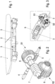
- FIG. 2 The actuator according to the invention is shown in more detail: A worm 5 of a first worm drive S1 is driven via the output shaft 4 of the electric motor.
- the worm 5 cooperates with a worm wheel 6, which drives the worm 7 of a second worm drive S2.
- the intermediate shaft defined among other things by the components 6 and 7, is preloaded by means of spring elements.
- the worm 7 works on a worm wheel 8, via which - directly or indirectly - the adjusting shaft 3 is driven, or if the actuator is arranged in the middle, the adjusting shafts 3 extending to both sides are driven.
- step-up or reduction ratios for the first worm drive of the order of magnitude of approximately 10 and for the second worm drive of the order of magnitude of approximately 23 .
- the second worm drive should be geared in a ratio of approximately 2:1 to the first worm drive.
- Fig. 3 shows schematically the arrangement of the actuator Fig. 2 in relation to the electric motor 9 driving it, as well as the adjusting shafts 3, which lead to the mechanical adjusting devices for the air guiding device.
- the electric motor 9 is decoupled completely elastically, for example via special couplings or decoupling elements made of rubber, which are each provided on the front side of the electric motor 9.
Landscapes
- Engineering & Computer Science (AREA)
- General Engineering & Computer Science (AREA)
- Mechanical Engineering (AREA)
- Chemical & Material Sciences (AREA)
- Combustion & Propulsion (AREA)
- Transportation (AREA)
- Gear Transmission (AREA)
Description
- Die Erfindung betrifft einen Stellantrieb für eine aus einer Nicht-Gebrauchsstellung in unterschiedliche Gebrauchsstellungen verstellbare Luftleitvorrichtung an einem Fahrzeug mit einem steuerbaren Elektromotor, mit einem Untersetzungsgetriebe, sowie mit Mitteln zur mechanischen Übertragung der Stellkraft auf die Luftleitvorrichtung, wobei die Luftleitvorrichtung ein Heckspoiler des Fahrzeugs ist.
- Bei Kraftfahrzeugen, insbesondere bei sportlichen Kraftfahrzeugen werden zur Erhöhung des Abtriebs bzw. zur besseren Straßenhaftung und insgesamt zur Verbesserung der Straßenlage und zum optimalen Stabilisieren des Fahrzeugs Luftleitvorrichtungen angebracht, die entweder lediglich aus einer Nicht-Gebrauchsstellung in eine Gebrauchsstellung, unter Umständen aber auch in eine Vielzahl von unterschiedlichen Gebrauchsstellungen bringbar sind. Die Verstellung wird üblicherweise über einen Elektromotor, vorzugsweise einen Gleichstrom-Elektromotor, der mittels eines Steuergeräts in Abhängigkeit von den jeweils erforderlichen Einstellungen der Luftleitvorrichtung ansteuerbar ist. Über ein diesem Elektromotor nachgeschaltetes Unter- bzw. Übersetzungsgetriebe und über Mittel zur mechanischen Übertragung der vom Elektromotor aufgebrachten Stellkraft auf die Luftleitvorrichtung wird deren Verstellung bewirkt. Die technischen Anforderungen an einen solchen Stellantrieb bei modernen Kraftfahrzeugen sind relativ hoch: Es wird ein relativ einfacher, störungsunanfälliger und sehr kompakter Aufbau bei geringstem Gewicht gefordert und gleichzeitig soll ein möglichst geräuscharmer bzw. geräuschloser Betrieb möglich sein.
- Aus dem Stand der Technik sind eine Reihe von Lösungen bekanntgeworden, mit denen versucht wird, der sich stellenden Problematik gerecht zu werden. So offenbart die
DE 103 48 284 A1 einen Stellantrieb für eine Luftleitvorrichtung, insbesondere für einen Heckspoiler eines Fahrzeugs, der mit einem vom Elektromotor angetriebenen Untersetzungsgetriebe über einen Spindelantrieb die Verstellung des Heckspoilers bewirkt. Aus derDE 10 2008 024 893 A1 ist eine Lösung bekannt geworden, bei der über ein separates Montageelement die Antriebseinrichtung für die Luftleitvorrichtung von der Karosserie des Kraftfahrzeugs entkoppelt angeordnet werden soll, um eine Geräuschminimierung erreichen zu können. - Aus der
WO 2008/041757 A1 ist eine Stellantriebsvorrichtung bekannt geworden, bei der über ein vom Elektromotor angetriebenes, zentral angeordnetes Übersetzungsgetriebe und eine von diesem angetriebenen Verstellwelle über mit Zahnrädern auf der Verstellwelle zusammenwirkende Zahnstangen ein Aus- bzw. Einfahren einer Luftleitvorrichtung erreicht werden soll. - Die
DE 37 11 386 A1 und dieUS 4 925 236 offenbaren Stellantriebe für Luftleitvorrichtungen, bei denen der Elektromotor über eine Schnecke und ein Schneckenrad und zum Teil weitere Getriebeelemente die Verstellung der Luftleitvorrichtung bewirkt. Diesen Lösungen liegt offensichtlich die Erkenntnis zugrunde, dass mit Schneckentrieben hohe bis sehr hohe Untersetzungen erreicht werden können und dass Schneckentriebe zu den Getriebevorrichtungen mit den geringsten Geräuschentwicklungen gehören. Außerdem sind Schneckentriebe in aller Regel selbsthemmend. - Die
DE 43 23 938 zeigt und beschreibt eine mit einer Heck-Beobachtungsspiegelvorrichtung kombinierte Luftleitvorrichtung für ein Fahrzeug. Bei diesem System sind zwei Schnecken-/Schneckenrad-Triebe kombiniert, um die Synchronisation der Bewegungen von Luftleitvorrichtung und Heck-Beobachtungsspiegelvorrichtung gewährleisten zu können. -
DE 101 60 056 A1 offenbart einen Zahnradantrieb eine Heizungs- und Belüftungsanlage.US 5 570 606 A1 offenbart ein Untersetzungsgetriebe von Kameras.CN 201 944 199 U offenbart einen Stellabtreib mit Schneckentrieben.
Von den Motorrädern BMW R 1150 RT und BMW R 1100 RT sind jeweils Windschilde mit einem Stellantrieb bekannt, wobei der Stellantrieb einen steuerbaren Elektromotor und ein Untersetzungsgetriebe aufweist. Das Untersetzungsgetriebe weist einen ersten, über seine Schnecke an die Abtriebswelle des Elektromotors gekoppelten Schneckentrieb auf, dessen Schneckenrad mit einer Schnecke eines zweiten Schneckentriebs in Wirkverbindung bringbar ist, dessen Schneckenrad die Verstellwelle für die Luftleitvorrichtung antreibt, wobei der erste Schneckentrieb größer als der zweite Schneckentrieb übersetzt ist.
EP 0 685 385 B1 offenbart eine Einrichtung zum Verstellen eines Windschildes eines Motorrads mit Zwischengetrieben, die selbsthemmend sind. - Der Erfindung liegt die Aufgabe zugrunde, einen Stellantrieb für eine als Heckspoiler ausgebildete Luftleitvorrichtung anzubieten, die sich - wie bereits erwähnt - durch sehr kompakte und gewichtssparende Bauweise mit minimaler Geräuschentwicklung auszeichnet und die für die unterschiedlichen Stellungen der Luftleitvorrichtungen auf den Gebrauch von zusätzlichen Positionierungs- bzw. Fixierungselemente verzichten kann.
- Diese Aufgabe wird durch einen Stellantrieb nach Anspruch 1 gelöst. Das Untersetzungsgetriebe des Stellantriebs weist einen ersten, über seine Schnecke an die Antriebswelle des Elektromotors gekoppelten Schneckentrieb auf, dessen Schneckenrad mit einer Schnecke eines zweiten Schneckentriebs in Wirkverbindung bringbar ist, dessen Schneckenrad die Verstellwelle für die Luftleitvorrichtung antreibt.
- Dabei ist der erste Schneckentrieb kleiner als der zweite Schneckentrieb übersetzt. In zweckmäßiger Weitergestaltung des Gegenstandes der Erfindung kann das Übersetzungsverhältnis des zweiten Schneckentriebs zum ersten Schneckentrieb in etwa 2:1 betragen.
- Ein Stellantrieb nach der Erfindung kommt vorzugsweise mit einer Antriebseinheit - auch bei relativ ausladenden und unter Umständen mit höheren Gewichten ausgestatten Luftleitvorrichtungen - aus; insbesondere dann, wenn das Schneckenrad des zweiten Schneckentriebs in etwa mittig auf der vom ihm angetriebenen Verstellwelle angeordnet ist. Damit wird eine mittige Anordnung des Stellantriebs und somit eine in jeder Beziehung gleichmäßige Übertragung der Verstellkräfte auf die in aller Regel seitlich außen angeordneten Verstellmittel für die Luftleitvorrichtung erreicht.
- Weitere Merkmale und Einzelheiten des Gegenstandes der Erfindung werden anhand eines in der Zeichnung vereinfacht dargestellten Ausführungsbeispiels nachfolgend näher beschrieben.
- Es zeigt:
-
Fig. 1 eine Luftleitvorrichtung schematisch mit einem zentral angeordneten Stellantrieb nach der Erfindung; -
Fig. 2 den Aufbau des Untersetzungsgetriebes eines Stellantriebs nach der Erfindung
und -
Fig. 3 eine Gesamtansicht eines nach der Erfindung aufgebauten Stellantriebs. -
Fig. 1 zeigt eine Luftleitvorrichtung 1, ein in beliebige Positionen zu einem Kraftfahrzeug ausfahrbares Spoilerblatt bzw. einen sog. Heckspoiler, die z.B. im Heckbereich eines sportlichen Kraftfahrzeuges angeordnet sein kann. Eine solche Luftleitvorrichtung 1 ist zumindest zwischen einer Gebrauchsstellung, bei der sie aus der Karosseriekontur des Fahrzeugs in eine abgehobene Position ausgefahren ist und einer Nicht-Gebrauchsstellung, in der sie in sie umgebende Karosserieteile des Fahrzeuges annähernd formangepasst eingefahren bzw. zumindest in eine die Luftströmung wenig bis gar nicht beeinflussende Position gebracht ist, verstellbar. Diese Verstellbewegung wird über eine Antriebsvorrichtung 2 bewirkt. Diese Antriebsvorrichtung 2 ist üblicherweise aufgebaut aus einem Elektromotor und einem mit dem Elektromotor zusammenwirkenden Untersetzungsgetriebe. Das Untersetzungsgetriebe wirkt auf eine Antriebswelle 3, die mit Mitteln zur mechanischen Übertragung der von der Antriebsvorrichtung 2 ausgehenden Stellkraft auf die Luftleitvorrichtung 1 zusammenwirkt. Diese Mittel zur mechanischen Übertragung der Stellkraft sind in an sich bekannter Weise aus dem Stand der Technik bekannt; auf sie soll hier als nicht zum Gegenstand der Erfindung gehörig nicht näher eingegangen werden. - In
Fig. 2 ist der Stellantrieb nach der Erfindung näher dargestellt: Über die Abtriebswelle 4 des Elektromotors wird eine Schnecke 5 eines ersten Schneckentriebs S1 angetrieben. Die Schnecke 5 wirkt mit einem Schneckenrad 6 zusammen, das die Schnecke 7 eines zweiten Schneckentriebs S2 antreibt. Um das Verdrehspiel der Abtriebswelle 4 zu reduzieren, wird die Zwischenwelle, definiert u.a. über die Bauteile 6 und 7, mittels Federelemente vorgespannt. Die Schnecke 7 arbeitet auf ein Schneckenrad 8, über das - direkt oder indirekt - die Verstellwelle 3 angetrieben wird, bzw. bei mittlerer Anordnung des Stellantriebs die nach beiden Seiten abgehenden Verstellwellen 3 angetrieben werden. - Um die Vorteile der Verwendung eines Schneckentriebs für einen solchen Stellantrieb optimal nutzen zu können, ist es zweckmäßig, Über- bzw. Untersetzungsverhältnisse für den ersten Schneckentrieb in der Größenordnung von ca. 10 und für den zweiten Schneckentrieb in der Größenordnung von ca. 23 zu wählen. In jedem Fall sollte der zweite Schneckentrieb in einem Verhältnis von etwa 2:1 zum ersten Schneckentrieb übersetzt sein. Mit einem solchen Über- bzw. Untersetzungsverhältnis wird einerseits größtmögliche Selbsthemmung im Getriebe erreicht, so dass die Luftleitvorrichtung in jeder beliebigen Positionierung ohne zusätzliche Positionier- bzw. Arretierungsmittel auch bei höheren Geschwindigkeiten des Fahrzeugs bzw. höheren Winddrücken unveränderlich stehenbleibt erreicht; andererseits ist damit auch eine kaum wahrnehmbare Geräuschentwicklung umsetzbar.
-
Fig. 3 zeigt schematisch die Anordnung des Stellantriebs nachFig. 2 in Bezug auf den diesen antreibenden Elektromotor 9, sowie die Verstellwellen 3, die zu den mechanischen Stellvorrichtungen für die Luftleitvorrichtung führen. Der Elektromotor 9 wird hierbei komplett elastisch entkoppelt, z.B. über spezielle Kupplungen bzw. Entkopplungselemente aus Gummi, welche jeweils stirnseitig am Elektromotor 9 vorgesehen sind. -
- S1
- erster Schneckentrieb
- S2
- zweiter Schneckentrieb
- 1
- Luftleitvorrichtung (Heckspoiler)
- 2
- Antriebsvorrichtung
- 3
- Verstellwelle
- 4
- Abtriebswelle
- 5
- Schnecke
- 6
- Schneckenrad
- 7
- Schnecke
- 8
- Schneckenrad
- 9
- Elektromotor
Claims (5)
- Stellantrieb einer aus einer Nicht-Gebrauchsstellung in unterschiedliche Gebrauchsstellungen verstellbaren Luftleitvorrichtung (1) an einem Fahrzeug, wobei die Luftleitvorrichtung (1) ein Heckspoiler des Fahrzeugs ist, mit einem steuerbaren Elektromotor (9) und mit einem Untersetzungsgetriebe (S1; S2), sowie mit Mitteln zur mechanischen Übertragung der Stellkraft auf die Luftleitvorrichtung (1), dadurch gekennzeichnet, dass das Untersetzungsgetriebe (S1; S2) einen ersten, über seine Schnecke (5) an die Abtriebswelle (4) des Elektromotors (9) gekoppelten Schneckentrieb (S1) aufweist, dessen Schneckenrad (6) mit einer Schnecke (7) eines zweiten Schneckentriebs (S2) in Wirkverbindung bringbar ist, dessen Schneckenrad (8) die Verstellwelle (3) für die Luftleitvorrichtung (1) antreibt, wobei der erste Schneckentrieb (S1) kleiner als der zweite Schneckentrieb (S2) übersetzt ist.
- Stellantrieb nach Anspruch 1, dadurch gekennzeichnet, dass der zweite Schneckentrieb (S2) in etwa im Verhältnis 2:1 zum ersten Schneckentrieb (S1) untersetzt ist.
- Stellantrieb nach einem der vorstehenden Ansprüche, dadurch gekennzeichnet, dass die zweite Stufe selbsthemmend und die erste Stufe wirkungsgradoptimiert ausgelegt ist.
- Stellantrieb nach einem der vorstehenden Ansprüche, dadurch gekennzeichnet, dass das Schneckenrad (8) des zweiten Schneckentriebs (S2) in etwa mittig zu bzw. auf der von ihm angetriebenen Verstellwelle/Verstellwellen (3) angeordnet ist.
- Stellantrieb für eine Luftleitvorrichtung an einem Fahrzeug an einem der vorhergehenden Ansprüchen, dadurch gekennzeichnet, dass das Fahrzeug ein Kraftfahrzeug ist.
Applications Claiming Priority (2)
| Application Number | Priority Date | Filing Date | Title |
|---|---|---|---|
| DE102014012292.1A DE102014012292A1 (de) | 2014-08-22 | 2014-08-22 | Stellantrieb für eine Luftleitvorrichtung |
| PCT/EP2015/068885 WO2016026828A1 (de) | 2014-08-22 | 2015-08-18 | Stellantrieb für eine luftleitvorrichtung |
Publications (3)
| Publication Number | Publication Date |
|---|---|
| EP3183162A1 EP3183162A1 (de) | 2017-06-28 |
| EP3183162B1 EP3183162B1 (de) | 2019-11-06 |
| EP3183162B2 true EP3183162B2 (de) | 2023-11-15 |
Family
ID=54062713
Family Applications (1)
| Application Number | Title | Priority Date | Filing Date |
|---|---|---|---|
| EP15759408.6A Active EP3183162B2 (de) | 2014-08-22 | 2015-08-18 | Stellantrieb für eine luftleitvorrichtung |
Country Status (5)
| Country | Link |
|---|---|
| US (1) | US10670114B2 (de) |
| EP (1) | EP3183162B2 (de) |
| CN (1) | CN107074305B (de) |
| DE (1) | DE102014012292A1 (de) |
| WO (1) | WO2016026828A1 (de) |
Families Citing this family (28)
| Publication number | Priority date | Publication date | Assignee | Title |
|---|---|---|---|---|
| DE102016120357B4 (de) * | 2016-10-25 | 2024-02-15 | Dr. Ing. H.C. F. Porsche Aktiengesellschaft | Schneckengetriebe |
| CN106788185A (zh) * | 2017-01-19 | 2017-05-31 | 苏州绿豆豆软件科技有限公司 | 多级蜗轮蜗杆伸缩装置、伸缩杆、调向系统及方法 |
| FR3070942B1 (fr) * | 2017-09-08 | 2019-09-13 | Compagnie Plastic Omnium | Ouvrant arriere de vehicule automobile comprenant un module amovible |
| EP3483477B1 (de) * | 2017-11-08 | 2021-01-20 | Magna Auteca GmbH | Antriebsanordnung |
| CN108116516A (zh) * | 2018-02-02 | 2018-06-05 | 深圳市车咪云创科技有限公司 | 汽车升降尾翼及系统 |
| DE102018104024B4 (de) | 2018-02-22 | 2025-03-06 | Dr. Ing. H.C. F. Porsche Aktiengesellschaft | Stellelement für ein Luftleitelement eines Kraftfahrzeugs |
| DE102018106788A1 (de) * | 2018-03-22 | 2019-09-26 | Dewertokin Gmbh | Elektromotorischer Möbelantrieb mit einer Getriebeanordnung mit Zwischenwelle |
| DE102018108135A1 (de) | 2018-04-06 | 2019-10-10 | Dr. Ing. H.C. F. Porsche Aktiengesellschaft | Antriebseinheit |
| DE102018108480B3 (de) | 2018-04-10 | 2019-10-10 | Dr. Ing. H.C. F. Porsche Aktiengesellschaft | Heckspoiler-Stellantrieb |
| DE102018108481B3 (de) | 2018-04-10 | 2019-02-28 | Dr. Ing. H.C. F. Porsche Aktiengesellschaft | Stellantrieb für einen Heckspoiler eines Kraftfahrzeugs |
| CN108662087A (zh) * | 2018-08-10 | 2018-10-16 | 中山市智力星电机有限公司 | 一种新型的齿轮箱 |
| DE102019106231A1 (de) * | 2019-03-12 | 2020-09-17 | Dr. Ing. H.C. F. Porsche Aktiengesellschaft | Antriebseinheit |
| DE102019108269B4 (de) | 2019-03-29 | 2023-07-06 | Paragon Gmbh & Co. Kgaa | Luftleitvorrichtung mit Getriebe |
| CN110040076B (zh) * | 2019-05-23 | 2024-10-01 | 广州市海显电子有限公司 | 一种停车指示牌、车载液晶电视的电动手动一体翻转装置 |
| CN110762167A (zh) * | 2019-10-28 | 2020-02-07 | 孟宪月 | 一种直斜式三蜗杆空心轴减速机 |
| IT201900021075A1 (it) * | 2019-11-13 | 2021-05-13 | Bitron Spa | Sistema per regolare un dispositivo di deflessione aria su un autoveicolo |
| DE102020127715B4 (de) | 2020-10-21 | 2024-05-29 | Valmet Automotive Oy | Vorrichtung zum Antreiben einer verstellbaren Fahrzeugkomponente |
| DE102020134307B4 (de) | 2020-12-18 | 2024-01-25 | Valmet Automotive Oy | Getriebe und vorrichtung zum antreiben einer fahrzeugkomponente |
| DE102020134310A1 (de) | 2020-12-18 | 2022-06-23 | Valmet Automotive Oy | Antriebsvorrichtung zum bewegen einer verstellbaren fahrzeugkomponente |
| DE102020134716B4 (de) | 2020-12-22 | 2024-10-10 | Valmet Automotive Oy | Verlagerbares Bauteil eines Kraftfahrzeuges |
| CN112815064A (zh) * | 2021-01-26 | 2021-05-18 | 浙江捷昌线性驱动科技股份有限公司 | 一种线性致动器 |
| IT202100028976A1 (it) | 2021-11-16 | 2023-05-16 | Bitron Spa | Attuatore rotativo per aerodinamica attiva |
| CN114228848B (zh) * | 2021-12-30 | 2023-03-28 | 上海毓恬冠佳科技股份有限公司 | 一种可自由悬停的三段式汽车尾翼 |
| DE202022102909U1 (de) | 2022-05-25 | 2022-07-13 | Kipp Gmbh & Co Kg | Stellsystem für ein Kraftfahrzeug, mit einem Stellmotor, einem untersetzenden Getriebe und einem Spoiler |
| DE102023101060A1 (de) | 2023-01-17 | 2024-07-18 | Valmet Automotive Oy | Stellantrieb für eine Luftleitvorrichtung |
| DE102023114044A1 (de) | 2023-05-29 | 2024-12-05 | Valmet Automotive Oy | Antriebsvorrichtung für verschwenkbare fahrzeugteile mit wenigstens einer antriebseinheit und mit einer getriebeeinheit |
| WO2025023696A1 (ko) * | 2023-07-24 | 2025-01-30 | 주식회사 아모텍 | 액티브 리어 스포일러용 액추에이터 |
| DE102023126756A1 (de) * | 2023-09-29 | 2025-04-03 | Valmet Automotive Oy | Stellantrieb für eine luftleitvorrichtung |
Family Cites Families (23)
| Publication number | Priority date | Publication date | Assignee | Title |
|---|---|---|---|---|
| US2863325A (en) * | 1956-05-04 | 1958-12-09 | Phaostron Instr And Electronic | Gear train |
| US3847032A (en) * | 1972-05-11 | 1974-11-12 | H Moser | Torque equalizing drive |
| DE3711386A1 (de) | 1986-04-19 | 1987-10-22 | Webasto Werk Baier Kg W | Vorrichtung zum leiten der windstroemung an fahrzeugen |
| US4925236A (en) | 1987-05-22 | 1990-05-15 | Nippondenso Co., Ltd. | Automotive air spoiler device |
| DE4323938C2 (de) | 1992-07-23 | 1996-10-10 | Aisin Seiki | Heck-Beobachtungsspiegelvorrichtung für ein Fahrzeug |
| JP3542819B2 (ja) | 1994-02-24 | 2004-07-14 | ペンタックス株式会社 | 歯車装置 |
| DE4418954A1 (de) | 1994-05-31 | 1995-12-07 | Bayerische Motoren Werke Ag | Einrichtung zum Verstellen eines Windschildes für Fahrzeuge |
| US5557991A (en) * | 1995-03-24 | 1996-09-24 | Brodbeck; James L. | Calibration hand tool |
| AU784114B2 (en) * | 2000-12-12 | 2006-02-09 | Robert Bosch Gmbh | Gear drive for an electric motor |
| US20040256885A1 (en) | 2003-03-10 | 2004-12-23 | Bui Le Trong | Rear spoiler with motorized vertical and angle adjustability |
| DE10348284A1 (de) | 2003-10-17 | 2005-05-12 | Porsche Ag | Stellantrieb für einen Spoiler eines Kraftfahrzeugs, insbesondere für einen Heckspoiler |
| CN200971116Y (zh) * | 2006-05-08 | 2007-11-07 | 关亮 | 机动车辆的节能飞翼装置 |
| WO2008041757A1 (en) | 2006-09-28 | 2008-04-10 | Yoshiaki Takida | Functional device for automobile |
| USRE44158E1 (en) * | 2006-10-27 | 2013-04-16 | Torvec, Inc. | Full traction differential with hybrid gearing |
| DE102008024893B4 (de) | 2008-05-16 | 2019-06-19 | Dr. Ing. H.C. F. Porsche Aktiengesellschaft | Luftleiteinrichtung |
| DE102010038596A1 (de) * | 2010-07-29 | 2012-02-02 | Robert Bosch Gmbh | Verstellantrieb mit integriertem Überlastschutz |
| CN201944199U (zh) * | 2010-12-31 | 2011-08-24 | 浙江瑞德森机械有限公司 | 双级蜗轮减速机 |
| DE102012211182A1 (de) | 2012-06-28 | 2014-04-03 | Bayerische Motoren Werke Aktiengesellschaft | Verstelleinrichtung zum Verstellen eines Windschilds |
| CN203147000U (zh) * | 2013-03-19 | 2013-08-21 | 苏州市凯泰机械有限公司 | 一种二级蜗轮蜗杆和圆柱齿轮传动的阀门手动装置 |
| DE102013205246B3 (de) | 2013-03-25 | 2014-05-15 | Autoliv Development Ab | Gurtstrafferantrieb |
| CN203581155U (zh) * | 2013-11-28 | 2014-05-07 | 常熟理工学院 | 车用空气动力装置 |
| DE102015104111A1 (de) * | 2015-03-19 | 2016-09-22 | Witte Automotive Gmbh | Antriebsmechanismus mit Doppelschneckengetriebe |
| DE102018108481B3 (de) * | 2018-04-10 | 2019-02-28 | Dr. Ing. H.C. F. Porsche Aktiengesellschaft | Stellantrieb für einen Heckspoiler eines Kraftfahrzeugs |
-
2014
- 2014-08-22 DE DE102014012292.1A patent/DE102014012292A1/de not_active Withdrawn
-
2015
- 2015-08-18 EP EP15759408.6A patent/EP3183162B2/de active Active
- 2015-08-18 WO PCT/EP2015/068885 patent/WO2016026828A1/de not_active Ceased
- 2015-08-18 US US15/505,123 patent/US10670114B2/en active Active
- 2015-08-18 CN CN201580044425.5A patent/CN107074305B/zh active Active
Also Published As
| Publication number | Publication date |
|---|---|
| CN107074305A (zh) | 2017-08-18 |
| CN107074305B (zh) | 2020-04-07 |
| US20190154117A1 (en) | 2019-05-23 |
| EP3183162A1 (de) | 2017-06-28 |
| EP3183162B1 (de) | 2019-11-06 |
| DE102014012292A1 (de) | 2016-02-25 |
| WO2016026828A1 (de) | 2016-02-25 |
| US10670114B2 (en) | 2020-06-02 |
Similar Documents
| Publication | Publication Date | Title |
|---|---|---|
| EP3183162B2 (de) | Stellantrieb für eine luftleitvorrichtung | |
| EP3131794B1 (de) | Wischeranlage | |
| EP2119619B1 (de) | Kraftfahrzeug mit ausfahrbarer Luftleiteinrichtung | |
| EP3844046B1 (de) | Elektrisch verstellbare steer-by-wire lenksäule und kraftfahrzeug | |
| DE102014114639B4 (de) | Luftkontrollvorrichtung für die Kontrolle eines Luftstroms in ein Fahrzeug | |
| DE102014117816A1 (de) | Optimiertes Luftregelsystem für Fahrzeuge | |
| DE102007055246A1 (de) | Anzeigeeinrichtung in einem Kraftfahrzeug | |
| EP3112237B1 (de) | Kraftfahrzeug mit einer luftleitelementanordnung | |
| DE102020126146B4 (de) | Windschutzvorrichtung für ein fahrzeug | |
| DE102015223485A1 (de) | Höheneinsteller für einen fahrzeugsitz, fahrzeugsitz | |
| DE102019200911A1 (de) | Eingabemodul für ein Steer-by-Wire-System mit einem Bedienelement und einem mit dem Bedienelement gekoppelten Aktuator | |
| DE202012013279U1 (de) | Baugruppe mit einem Gurthöhenversteller und einem Gurtbringer | |
| DE102015115035A1 (de) | Verriegelungssystem für eine Sitzanordnung eines Kraftfahrzeugs | |
| DE102013111412A1 (de) | Rahmenanordnung einer KFZ-Karosserie | |
| DE102018102824A1 (de) | Antriebseinheit, insbesondere für ein Luftleitelement eines Kraftfahrzeugs | |
| EP3898301B1 (de) | Innenraumeinrichtung für ein kraftfahrzeug | |
| DE102005015438B4 (de) | Servolenkung | |
| DE102015008474A1 (de) | Kraftfahrzeug mit einer Luftleitelementanordnung | |
| DE102014110394A1 (de) | Luftleitvorrichtung, Fahrzeug und Verfahren zum Betrieb einer Luftleitvorrichtung | |
| DE102012210894A1 (de) | Wischanlage, Steuereinrichtung für eine solche Wischanlage und Verfahren zum Betrieb der Wischanlage | |
| DE102017109669A1 (de) | Befestigungsvorrichtung sowie Verstellverfahren für eine Fahrzeugeinrichtung | |
| DE102009019602B3 (de) | Bewegungseinrichtung für ein Karosserieteil | |
| DE102006000849B3 (de) | Dach für ein Kraftfahrzeug | |
| DE102019128307A1 (de) | Antriebsvorrichtung für ein verstellbares Luftleitelement eines Kraftfahrzeugs und eine Luftleitvorrichtung | |
| DE102011121265A1 (de) | Verschiebbarer Bedienelementträger |
Legal Events
| Date | Code | Title | Description |
|---|---|---|---|
| STAA | Information on the status of an ep patent application or granted ep patent |
Free format text: STATUS: THE INTERNATIONAL PUBLICATION HAS BEEN MADE |
|
| PUAI | Public reference made under article 153(3) epc to a published international application that has entered the european phase |
Free format text: ORIGINAL CODE: 0009012 |
|
| STAA | Information on the status of an ep patent application or granted ep patent |
Free format text: STATUS: REQUEST FOR EXAMINATION WAS MADE |
|
| 17P | Request for examination filed |
Effective date: 20170313 |
|
| AK | Designated contracting states |
Kind code of ref document: A1 Designated state(s): AL AT BE BG CH CY CZ DE DK EE ES FI FR GB GR HR HU IE IS IT LI LT LU LV MC MK MT NL NO PL PT RO RS SE SI SK SM TR |
|
| AX | Request for extension of the european patent |
Extension state: BA ME |
|
| RIN1 | Information on inventor provided before grant (corrected) |
Inventor name: ULLRICH, STEFFEN Inventor name: SPIELBERG, DANIEL Inventor name: WEBER, SEBASTIAN Inventor name: GLASS, MATTHIAS Inventor name: HOLLERBAUM, BERND Inventor name: PREIS, JOHANNES Inventor name: PAUL, JOACHIM Inventor name: BIELESCH, HARALD Inventor name: HERRMANN, BERND Inventor name: LANG, JOHANNES Inventor name: FEIHL, MARC |
|
| DAV | Request for validation of the european patent (deleted) | ||
| DAX | Request for extension of the european patent (deleted) | ||
| REG | Reference to a national code |
Ref country code: DE Ref legal event code: R079 Ref document number: 502015010866 Country of ref document: DE Free format text: PREVIOUS MAIN CLASS: B62D0035000000 Ipc: F16H0001220000 |
|
| GRAP | Despatch of communication of intention to grant a patent |
Free format text: ORIGINAL CODE: EPIDOSNIGR1 |
|
| STAA | Information on the status of an ep patent application or granted ep patent |
Free format text: STATUS: GRANT OF PATENT IS INTENDED |
|
| RIC1 | Information provided on ipc code assigned before grant |
Ipc: F16H 1/16 20060101ALI20190423BHEP Ipc: B62D 35/00 20060101ALI20190423BHEP Ipc: F16H 1/22 20060101AFI20190423BHEP |
|
| INTG | Intention to grant announced |
Effective date: 20190520 |
|
| GRAS | Grant fee paid |
Free format text: ORIGINAL CODE: EPIDOSNIGR3 |
|
| GRAA | (expected) grant |
Free format text: ORIGINAL CODE: 0009210 |
|
| STAA | Information on the status of an ep patent application or granted ep patent |
Free format text: STATUS: THE PATENT HAS BEEN GRANTED |
|
| TPAC | Observations filed by third parties |
Free format text: ORIGINAL CODE: EPIDOSNTIPA |
|
| AK | Designated contracting states |
Kind code of ref document: B1 Designated state(s): AL AT BE BG CH CY CZ DE DK EE ES FI FR GB GR HR HU IE IS IT LI LT LU LV MC MK MT NL NO PL PT RO RS SE SI SK SM TR |
|
| REG | Reference to a national code |
Ref country code: GB Ref legal event code: FG4D Free format text: NOT ENGLISH |
|
| REG | Reference to a national code |
Ref country code: CH Ref legal event code: EP Ref country code: AT Ref legal event code: REF Ref document number: 1199142 Country of ref document: AT Kind code of ref document: T Effective date: 20191115 |
|
| REG | Reference to a national code |
Ref country code: DE Ref legal event code: R096 Ref document number: 502015010866 Country of ref document: DE |
|
| REG | Reference to a national code |
Ref country code: IE Ref legal event code: FG4D Free format text: LANGUAGE OF EP DOCUMENT: GERMAN |
|
| REG | Reference to a national code |
Ref country code: NL Ref legal event code: MP Effective date: 20191106 |
|
| REG | Reference to a national code |
Ref country code: LT Ref legal event code: MG4D |
|
| PG25 | Lapsed in a contracting state [announced via postgrant information from national office to epo] |
Ref country code: GR Free format text: LAPSE BECAUSE OF FAILURE TO SUBMIT A TRANSLATION OF THE DESCRIPTION OR TO PAY THE FEE WITHIN THE PRESCRIBED TIME-LIMIT Effective date: 20200207 Ref country code: NO Free format text: LAPSE BECAUSE OF FAILURE TO SUBMIT A TRANSLATION OF THE DESCRIPTION OR TO PAY THE FEE WITHIN THE PRESCRIBED TIME-LIMIT Effective date: 20200206 Ref country code: SE Free format text: LAPSE BECAUSE OF FAILURE TO SUBMIT A TRANSLATION OF THE DESCRIPTION OR TO PAY THE FEE WITHIN THE PRESCRIBED TIME-LIMIT Effective date: 20191106 Ref country code: BG Free format text: LAPSE BECAUSE OF FAILURE TO SUBMIT A TRANSLATION OF THE DESCRIPTION OR TO PAY THE FEE WITHIN THE PRESCRIBED TIME-LIMIT Effective date: 20200206 Ref country code: FI Free format text: LAPSE BECAUSE OF FAILURE TO SUBMIT A TRANSLATION OF THE DESCRIPTION OR TO PAY THE FEE WITHIN THE PRESCRIBED TIME-LIMIT Effective date: 20191106 Ref country code: LV Free format text: LAPSE BECAUSE OF FAILURE TO SUBMIT A TRANSLATION OF THE DESCRIPTION OR TO PAY THE FEE WITHIN THE PRESCRIBED TIME-LIMIT Effective date: 20191106 Ref country code: PT Free format text: LAPSE BECAUSE OF FAILURE TO SUBMIT A TRANSLATION OF THE DESCRIPTION OR TO PAY THE FEE WITHIN THE PRESCRIBED TIME-LIMIT Effective date: 20200306 Ref country code: NL Free format text: LAPSE BECAUSE OF FAILURE TO SUBMIT A TRANSLATION OF THE DESCRIPTION OR TO PAY THE FEE WITHIN THE PRESCRIBED TIME-LIMIT Effective date: 20191106 Ref country code: PL Free format text: LAPSE BECAUSE OF FAILURE TO SUBMIT A TRANSLATION OF THE DESCRIPTION OR TO PAY THE FEE WITHIN THE PRESCRIBED TIME-LIMIT Effective date: 20191106 Ref country code: LT Free format text: LAPSE BECAUSE OF FAILURE TO SUBMIT A TRANSLATION OF THE DESCRIPTION OR TO PAY THE FEE WITHIN THE PRESCRIBED TIME-LIMIT Effective date: 20191106 |
|
| PG25 | Lapsed in a contracting state [announced via postgrant information from national office to epo] |
Ref country code: IS Free format text: LAPSE BECAUSE OF FAILURE TO SUBMIT A TRANSLATION OF THE DESCRIPTION OR TO PAY THE FEE WITHIN THE PRESCRIBED TIME-LIMIT Effective date: 20200306 Ref country code: HR Free format text: LAPSE BECAUSE OF FAILURE TO SUBMIT A TRANSLATION OF THE DESCRIPTION OR TO PAY THE FEE WITHIN THE PRESCRIBED TIME-LIMIT Effective date: 20191106 Ref country code: RS Free format text: LAPSE BECAUSE OF FAILURE TO SUBMIT A TRANSLATION OF THE DESCRIPTION OR TO PAY THE FEE WITHIN THE PRESCRIBED TIME-LIMIT Effective date: 20191106 |
|
| PG25 | Lapsed in a contracting state [announced via postgrant information from national office to epo] |
Ref country code: AL Free format text: LAPSE BECAUSE OF FAILURE TO SUBMIT A TRANSLATION OF THE DESCRIPTION OR TO PAY THE FEE WITHIN THE PRESCRIBED TIME-LIMIT Effective date: 20191106 |
|
| PG25 | Lapsed in a contracting state [announced via postgrant information from national office to epo] |
Ref country code: ES Free format text: LAPSE BECAUSE OF FAILURE TO SUBMIT A TRANSLATION OF THE DESCRIPTION OR TO PAY THE FEE WITHIN THE PRESCRIBED TIME-LIMIT Effective date: 20191106 Ref country code: DK Free format text: LAPSE BECAUSE OF FAILURE TO SUBMIT A TRANSLATION OF THE DESCRIPTION OR TO PAY THE FEE WITHIN THE PRESCRIBED TIME-LIMIT Effective date: 20191106 Ref country code: EE Free format text: LAPSE BECAUSE OF FAILURE TO SUBMIT A TRANSLATION OF THE DESCRIPTION OR TO PAY THE FEE WITHIN THE PRESCRIBED TIME-LIMIT Effective date: 20191106 Ref country code: CZ Free format text: LAPSE BECAUSE OF FAILURE TO SUBMIT A TRANSLATION OF THE DESCRIPTION OR TO PAY THE FEE WITHIN THE PRESCRIBED TIME-LIMIT Effective date: 20191106 Ref country code: RO Free format text: LAPSE BECAUSE OF FAILURE TO SUBMIT A TRANSLATION OF THE DESCRIPTION OR TO PAY THE FEE WITHIN THE PRESCRIBED TIME-LIMIT Effective date: 20191106 |
|
| REG | Reference to a national code |
Ref country code: DE Ref legal event code: R026 Ref document number: 502015010866 Country of ref document: DE |
|
| PLBI | Opposition filed |
Free format text: ORIGINAL CODE: 0009260 |
|
| PG25 | Lapsed in a contracting state [announced via postgrant information from national office to epo] |
Ref country code: SM Free format text: LAPSE BECAUSE OF FAILURE TO SUBMIT A TRANSLATION OF THE DESCRIPTION OR TO PAY THE FEE WITHIN THE PRESCRIBED TIME-LIMIT Effective date: 20191106 Ref country code: SK Free format text: LAPSE BECAUSE OF FAILURE TO SUBMIT A TRANSLATION OF THE DESCRIPTION OR TO PAY THE FEE WITHIN THE PRESCRIBED TIME-LIMIT Effective date: 20191106 |
|
| 26 | Opposition filed |
Opponent name: KIPP GMBH & CO KG / PRIMUS PRAEZISIONSTECHNIK GMBH & CO. KG Effective date: 20200804 Opponent name: PARAGON MOVASYS GMBH Effective date: 20200805 |
|
| PLAX | Notice of opposition and request to file observation + time limit sent |
Free format text: ORIGINAL CODE: EPIDOSNOBS2 |
|
| PG25 | Lapsed in a contracting state [announced via postgrant information from national office to epo] |
Ref country code: SI Free format text: LAPSE BECAUSE OF FAILURE TO SUBMIT A TRANSLATION OF THE DESCRIPTION OR TO PAY THE FEE WITHIN THE PRESCRIBED TIME-LIMIT Effective date: 20191106 |
|
| PLBB | Reply of patent proprietor to notice(s) of opposition received |
Free format text: ORIGINAL CODE: EPIDOSNOBS3 |
|
| PG25 | Lapsed in a contracting state [announced via postgrant information from national office to epo] |
Ref country code: IT Free format text: LAPSE BECAUSE OF FAILURE TO SUBMIT A TRANSLATION OF THE DESCRIPTION OR TO PAY THE FEE WITHIN THE PRESCRIBED TIME-LIMIT Effective date: 20191106 |
|
| PG25 | Lapsed in a contracting state [announced via postgrant information from national office to epo] |
Ref country code: MC Free format text: LAPSE BECAUSE OF FAILURE TO SUBMIT A TRANSLATION OF THE DESCRIPTION OR TO PAY THE FEE WITHIN THE PRESCRIBED TIME-LIMIT Effective date: 20191106 |
|
| REG | Reference to a national code |
Ref country code: CH Ref legal event code: PL |
|
| PG25 | Lapsed in a contracting state [announced via postgrant information from national office to epo] |
Ref country code: CH Free format text: LAPSE BECAUSE OF NON-PAYMENT OF DUE FEES Effective date: 20200831 Ref country code: LI Free format text: LAPSE BECAUSE OF NON-PAYMENT OF DUE FEES Effective date: 20200831 Ref country code: LU Free format text: LAPSE BECAUSE OF NON-PAYMENT OF DUE FEES Effective date: 20200818 |
|
| REG | Reference to a national code |
Ref country code: BE Ref legal event code: MM Effective date: 20200831 |
|
| PG25 | Lapsed in a contracting state [announced via postgrant information from national office to epo] |
Ref country code: IE Free format text: LAPSE BECAUSE OF NON-PAYMENT OF DUE FEES Effective date: 20200818 Ref country code: BE Free format text: LAPSE BECAUSE OF NON-PAYMENT OF DUE FEES Effective date: 20200831 |
|
| REG | Reference to a national code |
Ref country code: AT Ref legal event code: MM01 Ref document number: 1199142 Country of ref document: AT Kind code of ref document: T Effective date: 20200818 |
|
| PG25 | Lapsed in a contracting state [announced via postgrant information from national office to epo] |
Ref country code: AT Free format text: LAPSE BECAUSE OF NON-PAYMENT OF DUE FEES Effective date: 20200818 |
|
| PG25 | Lapsed in a contracting state [announced via postgrant information from national office to epo] |
Ref country code: TR Free format text: LAPSE BECAUSE OF FAILURE TO SUBMIT A TRANSLATION OF THE DESCRIPTION OR TO PAY THE FEE WITHIN THE PRESCRIBED TIME-LIMIT Effective date: 20191106 Ref country code: MT Free format text: LAPSE BECAUSE OF FAILURE TO SUBMIT A TRANSLATION OF THE DESCRIPTION OR TO PAY THE FEE WITHIN THE PRESCRIBED TIME-LIMIT Effective date: 20191106 Ref country code: CY Free format text: LAPSE BECAUSE OF FAILURE TO SUBMIT A TRANSLATION OF THE DESCRIPTION OR TO PAY THE FEE WITHIN THE PRESCRIBED TIME-LIMIT Effective date: 20191106 |
|
| PG25 | Lapsed in a contracting state [announced via postgrant information from national office to epo] |
Ref country code: MK Free format text: LAPSE BECAUSE OF FAILURE TO SUBMIT A TRANSLATION OF THE DESCRIPTION OR TO PAY THE FEE WITHIN THE PRESCRIBED TIME-LIMIT Effective date: 20191106 |
|
| APAH | Appeal reference modified |
Free format text: ORIGINAL CODE: EPIDOSCREFNO |
|
| APBM | Appeal reference recorded |
Free format text: ORIGINAL CODE: EPIDOSNREFNO |
|
| APBP | Date of receipt of notice of appeal recorded |
Free format text: ORIGINAL CODE: EPIDOSNNOA2O |
|
| APBQ | Date of receipt of statement of grounds of appeal recorded |
Free format text: ORIGINAL CODE: EPIDOSNNOA3O |
|
| APBU | Appeal procedure closed |
Free format text: ORIGINAL CODE: EPIDOSNNOA9O |
|
| P01 | Opt-out of the competence of the unified patent court (upc) registered |
Effective date: 20230530 |
|
| PUAH | Patent maintained in amended form |
Free format text: ORIGINAL CODE: 0009272 |
|
| STAA | Information on the status of an ep patent application or granted ep patent |
Free format text: STATUS: PATENT MAINTAINED AS AMENDED |
|
| 27A | Patent maintained in amended form |
Effective date: 20231115 |
|
| AK | Designated contracting states |
Kind code of ref document: B2 Designated state(s): AL AT BE BG CH CY CZ DE DK EE ES FI FR GB GR HR HU IE IS IT LI LT LU LV MC MK MT NL NO PL PT RO RS SE SI SK SM TR |
|
| REG | Reference to a national code |
Ref country code: DE Ref legal event code: R102 Ref document number: 502015010866 Country of ref document: DE |
|
| PGFP | Annual fee paid to national office [announced via postgrant information from national office to epo] |
Ref country code: DE Payment date: 20250827 Year of fee payment: 11 |
|
| PGFP | Annual fee paid to national office [announced via postgrant information from national office to epo] |
Ref country code: GB Payment date: 20250820 Year of fee payment: 11 |
|
| PGFP | Annual fee paid to national office [announced via postgrant information from national office to epo] |
Ref country code: FR Payment date: 20250829 Year of fee payment: 11 |