EP3182798B1 - Appareil a micro-ondes - Google Patents
Appareil a micro-ondes Download PDFInfo
- Publication number
- EP3182798B1 EP3182798B1 EP15201322.3A EP15201322A EP3182798B1 EP 3182798 B1 EP3182798 B1 EP 3182798B1 EP 15201322 A EP15201322 A EP 15201322A EP 3182798 B1 EP3182798 B1 EP 3182798B1
- Authority
- EP
- European Patent Office
- Prior art keywords
- microwave
- housing
- heated
- microwave apparatus
- cylindrical
- Prior art date
- Legal status (The legal status is an assumption and is not a legal conclusion. Google has not performed a legal analysis and makes no representation as to the accuracy of the status listed.)
- Active
Links
- 239000000463 material Substances 0.000 claims description 22
- 230000005855 radiation Effects 0.000 claims description 21
- 230000008878 coupling Effects 0.000 claims description 17
- 238000010168 coupling process Methods 0.000 claims description 17
- 238000005859 coupling reaction Methods 0.000 claims description 17
- 235000013305 food Nutrition 0.000 claims description 17
- 238000010438 heat treatment Methods 0.000 claims description 16
- 238000005303 weighing Methods 0.000 claims description 8
- 238000010257 thawing Methods 0.000 claims description 7
- 239000002245 particle Substances 0.000 claims description 4
- 238000001816 cooling Methods 0.000 claims description 3
- 230000009967 tasteless effect Effects 0.000 claims description 3
- 238000009833 condensation Methods 0.000 claims description 2
- 230000005494 condensation Effects 0.000 claims description 2
- 238000007373 indentation Methods 0.000 claims 1
- XLYOFNOQVPJJNP-UHFFFAOYSA-N water Substances O XLYOFNOQVPJJNP-UHFFFAOYSA-N 0.000 claims 1
- 235000013611 frozen food Nutrition 0.000 description 4
- 230000000694 effects Effects 0.000 description 3
- 230000001681 protective effect Effects 0.000 description 3
- 235000002595 Solanum tuberosum Nutrition 0.000 description 2
- 244000061456 Solanum tuberosum Species 0.000 description 2
- 235000013351 cheese Nutrition 0.000 description 2
- 238000006243 chemical reaction Methods 0.000 description 2
- 235000015243 ice cream Nutrition 0.000 description 2
- 238000000034 method Methods 0.000 description 2
- 235000012015 potatoes Nutrition 0.000 description 2
- 235000012773 waffles Nutrition 0.000 description 2
- 239000002918 waste heat Substances 0.000 description 2
- 241000251468 Actinopterygii Species 0.000 description 1
- 230000015572 biosynthetic process Effects 0.000 description 1
- 238000004140 cleaning Methods 0.000 description 1
- 238000001035 drying Methods 0.000 description 1
- 235000013399 edible fruits Nutrition 0.000 description 1
- 238000000605 extraction Methods 0.000 description 1
- 235000013372 meat Nutrition 0.000 description 1
- 238000001228 spectrum Methods 0.000 description 1
- 239000012780 transparent material Substances 0.000 description 1
- 235000013311 vegetables Nutrition 0.000 description 1
- 238000010792 warming Methods 0.000 description 1
Images

Classifications
-
- H—ELECTRICITY
- H05—ELECTRIC TECHNIQUES NOT OTHERWISE PROVIDED FOR
- H05B—ELECTRIC HEATING; ELECTRIC LIGHT SOURCES NOT OTHERWISE PROVIDED FOR; CIRCUIT ARRANGEMENTS FOR ELECTRIC LIGHT SOURCES, IN GENERAL
- H05B6/00—Heating by electric, magnetic or electromagnetic fields
- H05B6/64—Heating using microwaves
- H05B6/6408—Supports or covers specially adapted for use in microwave heating apparatus
- H05B6/6411—Supports or covers specially adapted for use in microwave heating apparatus the supports being rotated
-
- A—HUMAN NECESSITIES
- A21—BAKING; EDIBLE DOUGHS
- A21D—TREATMENT, e.g. PRESERVATION, OF FLOUR OR DOUGH, e.g. BY ADDITION OF MATERIALS; BAKING; BAKERY PRODUCTS; PRESERVATION THEREOF
- A21D17/00—Refreshing bakery products or recycling bakery products
- A21D17/004—Refreshing bakery products or recycling bakery products refreshing by thawing or heating
- A21D17/006—Refreshing bakery products or recycling bakery products refreshing by thawing or heating with microwaves
-
- H—ELECTRICITY
- H05—ELECTRIC TECHNIQUES NOT OTHERWISE PROVIDED FOR
- H05B—ELECTRIC HEATING; ELECTRIC LIGHT SOURCES NOT OTHERWISE PROVIDED FOR; CIRCUIT ARRANGEMENTS FOR ELECTRIC LIGHT SOURCES, IN GENERAL
- H05B6/00—Heating by electric, magnetic or electromagnetic fields
- H05B6/64—Heating using microwaves
- H05B6/6402—Aspects relating to the microwave cavity
-
- H—ELECTRICITY
- H05—ELECTRIC TECHNIQUES NOT OTHERWISE PROVIDED FOR
- H05B—ELECTRIC HEATING; ELECTRIC LIGHT SOURCES NOT OTHERWISE PROVIDED FOR; CIRCUIT ARRANGEMENTS FOR ELECTRIC LIGHT SOURCES, IN GENERAL
- H05B6/00—Heating by electric, magnetic or electromagnetic fields
- H05B6/64—Heating using microwaves
- H05B6/642—Cooling of the microwave components and related air circulation systems
-
- H—ELECTRICITY
- H05—ELECTRIC TECHNIQUES NOT OTHERWISE PROVIDED FOR
- H05B—ELECTRIC HEATING; ELECTRIC LIGHT SOURCES NOT OTHERWISE PROVIDED FOR; CIRCUIT ARRANGEMENTS FOR ELECTRIC LIGHT SOURCES, IN GENERAL
- H05B6/00—Heating by electric, magnetic or electromagnetic fields
- H05B6/64—Heating using microwaves
- H05B6/6447—Method of operation or details of the microwave heating apparatus related to the use of detectors or sensors
- H05B6/6464—Method of operation or details of the microwave heating apparatus related to the use of detectors or sensors using weight sensors
-
- H—ELECTRICITY
- H05—ELECTRIC TECHNIQUES NOT OTHERWISE PROVIDED FOR
- H05B—ELECTRIC HEATING; ELECTRIC LIGHT SOURCES NOT OTHERWISE PROVIDED FOR; CIRCUIT ARRANGEMENTS FOR ELECTRIC LIGHT SOURCES, IN GENERAL
- H05B6/00—Heating by electric, magnetic or electromagnetic fields
- H05B6/64—Heating using microwaves
- H05B6/70—Feed lines
- H05B6/707—Feed lines using waveguides
-
- H—ELECTRICITY
- H05—ELECTRIC TECHNIQUES NOT OTHERWISE PROVIDED FOR
- H05B—ELECTRIC HEATING; ELECTRIC LIGHT SOURCES NOT OTHERWISE PROVIDED FOR; CIRCUIT ARRANGEMENTS FOR ELECTRIC LIGHT SOURCES, IN GENERAL
- H05B2206/00—Aspects relating to heating by electric, magnetic, or electromagnetic fields covered by group H05B6/00
- H05B2206/04—Heating using microwaves
- H05B2206/044—Microwave heating devices provided with two or more magnetrons or microwave sources of other kind
Definitions
- the invention relates to a microwave device for items to be heated, in particular defrosted, in particular food items, to be heated within a short period of time.
- a microwave oven which has oven modules which are arranged in a row one behind the other.
- Each furnace module has a cylindrical housing jacket.
- a microwave radiation source is attached to the respective housing jacket.
- the microwave radiation sources of the oven modules arranged one behind the other in a row are preferably provided offset by the same angle in the circumferential direction.
- the microwave radiation source projects radially away from the associated furnace module.
- WO 2006/128212 A1 relates to a dipole antenna for amplifying a microwave field in a food heating device.
- JP H09 73981 A relates to a high-frequency heating device with two identically shaped waveguides, which each connect two high-frequency oscillators to a heating chamber, and a turntable on which an object to be heated is arranged,
- U.S. 3,745,291 A relates to the heating of articles using radio frequency energy in the microwave region of the electromagnetic spectrum and, more particularly, of articles that have inherently poor heat conduction, such as pneumatic rubber tires.
- WO 2004/046628 A2 relates to a structure of a dryer for household products which irradiates microwaves while a free cartridge is attached and rotated, and efficiently heats and dries it, and a method of controlling the drying process.
- EP 2 854 478 A1 relates to a microwave heating system comprising a bowl, a dome that can be adapted to the bowl so that a volume is formed by the bowl and the dome, and a rotor device adapted to support at least one reaction vessel and rotatably supported by the bowl.
- US 2015/093308 A1 relates to a device for the rotatable mounting of at least one reaction vessel in a microwave heating device.
- WO 2013/046718 A1 relates to a high frequency heater with an electrothermal heater.
- EP 0 190 430 A1 relates to a method and apparatus for heating food.
- the invention is based on the object of creating a microwave device of the type mentioned at the beginning with which it is possible within a short period of time of, for example, ⁇ 1 minute to heat edible goods, in particular food goods, in particular to thaw and thaw deep-frozen, frozen goods to make edible.
- the microwave device has an oven housing, to the housing jacket of which at least one microwave radiation source is coupled by means of a microwave coupling element, the microwave coupling element projecting away from the housing jacket in a distributed manner in the circumferential direction, and at least one item-holding device for the item is provided in the furnace housing, which can be rotated around a central axis by means of a drive device, the at least one item-holding device being formed by a turntable, which is provided for holding the item to be heated, in particular to be thawed, in a precise position is.
- microwave radiation sources for example, can be coupled to the housing jacket by means of associated microwave coupling elements, so that the inside of the cylindrical oven housing is uniformly distributed with optimal swirling of the microwave field.
- more than one item holding device can be provided for items to be heated, in particular items to be thawed, which are axially spaced from one another.
- a single item holding device for the items to be heated, in particular to be thawed is provided in the furnace housing, which is arranged axially in the center of the furnace housing and can be rotated about the central axis of rotation by means of the drive device.
- the housing jacket of the furnace housing has a heating device to prevent the formation of condensation.
- the heating device can be formed by an electrical resistance heater which surrounds the housing jacket. It is also possible for the housing jacket to consist at least partially of a material which, under the influence of microwaves, has such an eddy current loss that self-heating is caused.
- the turntable can be removed from the oven housing for loading with items to be heated, in particular defrosted, so that the turntable is equipped with items to be heated, in particular defrosted, from outside the microwave device and in the loaded state the microwave oven can be used.
- the turntable can be connected to the drive device, preferably in a torque-transmitting manner.
- This can be implemented, for example, by a positive connection, such as a tongue and groove connection, a locking pin connection or the like, between the turntable and the drive device.
- the respective microwave coupling device is preferably formed by a waveguide.
- the respective waveguide opens with its end remote from the associated microwave radiation source, preferably tangentially, into the housing jacket of the cylindrical furnace housing.
- the turntable is expediently designed with good holding means, which are provided at an equidistant distance along at least one pitch circle concentric to the central axis.
- the good holding means can consist of holes, recesses, recesses, loop elements, clamping elements, or the like. be educated.
- the turntable can, for example, be designed in the form of a disk over its entire surface with the holes and / or recesses and / or cutouts. Another possibility is that the turntable is designed as a web or rib structure with corresponding holes, loop elements and / or clamping elements, which are limited, i.e. formed, by web or rib edges to reduce weight.
- the turntable can be set up in such a way that the item to be heated is set in motion that does not represent a rotation about the central axis.
- This device can be implemented, for example, by a gear mechanism that moves the goods holding means arranged on the turntable about axes that deviate from the central axis.
- the material holding means are provided in the turntable, preferably evenly spaced along at least one pitch circle concentric to the central axis.
- the goods holding means formed in the turntable have clear dimensions which are adapted to the goods to be heated, in particular thawed, in such a way that the goods, in particular food items, extend axially defined through the turntable and are held in a precise and reliable position by the turntable .
- the goods holding means are designed with spaced apart, partial contact surfaces in order to allow steam and / or moisture to be dissipated between the turntable and the goods to be heated, in particular to be thawed.
- the partial contact surfaces can be realized, for example, in that the edge of the material holding means formed e.g. by holes is corrugated, toothed, or the like. is designed.
- the turntable is preferably made of a microwave-transparent material or of a hybrid, i.e. of parts which consist of a material that easily couples with microwaves.
- three to nine good holding means can be provided equidistantly along the at least one pitch circle.
- a collecting device made of microwave-permeable material is removably provided in the furnace housing for collecting moisture and / or dirt particles.
- the collecting device after being removed from the oven housing, can be cleaned, i.e. washed, manually or with the aid of a dishwasher.
- the drive device for the at least one holding device is preferably arranged in the area of the bottom of the oven housing.
- the bottom of the furnace housing can be formed with a central, cap-like bulge, through which a cavity is defined on the underside, in which the drive device formed by a motor is provided.
- the drive device can be surrounded by a microwave-reflecting cap element which is provided to be immovable.
- the cap element can be designed with a smooth surface.
- the cap element is provided rotatable about the central axis and for the diffusing microwave reflection with a non-smooth, for example ribbed, knobbed, corrugated and / or indented surface is trained.
- a non-smooth for example ribbed, knobbed, corrugated and / or indented surface
- the item held by the turntable and held precisely in position is not only exposed to microwaves radially on the outside, but also on its radial inner side by means of the microwave-reflective cap element, so that the microwaves have an even effect on the item and thus optimal Warming, in particular, thawing properties for the goods.
- the furnace housing can be cylindrical and have a cover with a protective device against leakage radiation.
- the protective device can form a ⁇ / 4 or ⁇ / 2 choke, for example, depending on the respective furnace load.
- the housing cover has a suction device with which the resulting moisture is sucked out of the furnace housing and discharged.
- the suction device can be formed by a suction fan.
- the housing cover is designed with perforation holes so that the warm air rises up in the furnace housing and flows out of the furnace housing through the perforation holes.
- the microwave device has a weighing device for determining the loading of the goods holding device.
- the weighing device can also be used to control the power of the microwave device. With the help of the weighing device, it is advantageously also possible to prevent incorrect loading of the microwave device according to the invention, e.g. with ham and cheese toast, potatoes or the like.
- the respective microwave radiation source is preferably formed by a magnetron to which a fan is connected for cooling, and the respective magnetron is fluidically connected to the cylindrical housing jacket by means of a pipe, through which the heat loss generated in the magnetron into the interior of the cylindrical furnace housing is initiated. It can be useful to provide a filter device in the respective flow channel.
- Such a design of the microwave device according to the invention has the advantage that the waste heat of the respective magnetron can be introduced into the interior of the cylindrical furnace housing with the aid of the associated fan in order to carry the moisture generated during the heating, in particular thawing of the goods, in particular food goods to apply said waste heat and to suck off the moisture from the interior of the cylindrical furnace housing by means of the suction device and to discharge it.
- the respective pipeline by means of which the associated magnetron is fluidically connected to the housing jacket, expediently opens tangentially into the cylindrical housing jacket.
- the microwave device according to the invention is preferably used for food items to be heated, in particular to be thawed, which have a defined shape and which are inserted into a dimensionally stable receiving casing body for heating, in particular thawing, into the microwave device.
- the goods to be thawed are preferably made up of a tasteless or a particular flavored dough material, in particular a waffle, such as is used in a similar way, for example, for ice cream.
- the mentioned food good can be, for example, vegetables and / or fruit and / or meat and / or fish or the like. that is prepared in pulpy and / or small pieces and, for example, frozen in a conical or truncated cone shape, e.g. in a freezer cabinet until it is sold.
- the dimensionally stable receiving casing bodies made from the dough material are stored until they are used, i.e. for combination with the frozen food product.
- the frozen food product is inserted into a suitable, dimensionally stable receiving casing body and then the dimensionally stable receiving casing body with the food product to be heated, in particular to be thawed, is inserted into the microwave device with the aid of the product holding device and that Microwave device switched on, so that within a short period of time, for example, less than a minute, the food item with the receptacle casing body is heated, in particular thawed, and is available for consumption.
- the microwave device according to the invention is able, for example, to heat frozen food items from -20 ° C. to + 80 ° C. within a short period of 1 minute.
- FIG. 1 illustrates an embodiment of the microwave device 10, which has an oven housing 12 with a cylindrical housing jacket 14.
- a number of microwave coupling elements 16 are coupled to the housing jacket 14 and project tangentially away from the cylindrical housing jacket 14, preferably evenly distributed in the circumferential direction.
- the microwave coupling elements 16 serve to couple associated microwave radiation sources 18 to the cylindrical oven housing 12 of the microwave device 10.
- the microwave radiation sources 18 are axially equidistant from one another by means of the associated microwave coupling elements 16.
- four microwave coupling elements 16 are illustrated, only the two microwave coupling elements at the end are shown in the drawing.
- the two central microwave coupling elements are only indicated by dash-dotted lines 20.
- microwave radiation sources can be used, depending on their output and the volume of the room to be heated.
- a number of microwave radiation sources 18 with their associated microwave coupling elements 16 are not axially offset but are arranged in a common plane distributed in the circumferential direction.
- a material holding device 22 is provided axially in the center of the cylindrical furnace housing 12 and can be driven about a central axis 26 by means of a drive device 24.
- the goods holding device 22 has a turntable 28 which is designed in particular for temporarily holding food goods to be heated or frozen and thawed with goods holding means 30.
- the good holding means 30 are provided along a pitch circle 32 concentric to the central axis 26 and spaced equidistantly from one another.
- the turntable 28 is designed with five or six good holding means 30.
- the good holding means 30 are, for example, designed as holes; they can, for example, also of recesses, cutouts, loop elements, clamping elements or the like. be educated.
- the drive device 24 provided for the goods holding device 22 formed by a rotary plate 28 is arranged in the region of the bottom 36 of the cylindrical furnace housing 12.
- the base 36 is designed with a cap-like bulge 37.
- the drive device 24 is arranged in the space delimited on the upper side by the bulge 37.
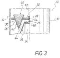
- Figure 3 illustrates an embodiment, wherein the drive device 24 formed by a motor is surrounded by a microwave-reflecting cap element 38, so that the food product 40 to be heated, in particular frozen and thawed, is not only on its radially outer side 42 but also on its radial side inside page 44 with microwaves is acted upon in order to bring about uniform and rapid heating, in particular thawing, of the food product 40.
- the cap element 38 can be provided immovably and formed with a smooth surface. Another possibility is that the cap element 38 is provided to be rotatable about the central axis 26 and is designed with a non-smooth, i.e. ribbed, knobbed, corrugated and / or indented surface for the diffusing microwave reflection.
- the food product 40 to be heated has, for example, a conical shape and is inserted into a conformal, dimensionally stable receiving casing body 46.
- the respective dimensionally stable receptacle casing body 46 consists of an edible, tasteless or flavored dough material, so that the food 40 can be eaten together with the receptacle casing body 46 after thawing and removal from the microwave device 10.
- the receptacle casing body 46 can be formed, for example, from a waffle, such as has been used up to now for eating ice cream portions.
- the Figures 1 and 2 also make it clear that the respective microwave radiation source 18 formed by a magnetron is connected to a fan 48 for cooling it.
- the respective microwave radiation source 18 is also fluidically connected to the cylindrical housing jacket 14 by means of a pipe 50; the respective pipeline 50 opens into the interior 34 of the cylindrical furnace housing 14 in a tangentially oriented manner.
- the heat loss generated in the microwave radiation sources 18 is introduced through the pipes 50 into the interior 34 of the cylindrical oven housing 12 in order to heat the moisture generated during the heating, in particular thawing of frozen food items 40 and to remove them from the microwave by means of a suction device 52.
- Suction device 10 The one formed by a fan
- the suction device 52 is arranged on the housing cover 54 of the cylindrical oven housing 12 of the microwave device 10.
- the housing cover 54 is preferably designed with a protective device against leakage radiation, which is designed as a ⁇ / 4 or ⁇ / 2 throttle depending on the furnace load.
- a device housing 56 is indicated by a thin dash-dotted line.
- Figure 2 also illustrates schematically a weighing device 58 which is assigned to the drive device 24.
- a weighing device 58 which is assigned to the drive device 24.
- the weighing device 58 is also suitable for the operation of the microwave device 10 in the event of incorrect loading - for example with ham and cheese toast, potatoes or the like. - to prevent.
- a collecting device 60 which is removably arranged in the furnace housing 12 and serves to collect moisture and / or dirt particles is also shown. After the collecting device 60 has been removed from the furnace housing 12, it can be cleaned in order to remove dirt particles and / or moisture from the collecting device 60. The cleaning can be done manually or automatically, for example by means of a dishwasher.
- the rotary plate 28 is detachably coupled to the drive shaft 62 of the drive device 24 by means of a form-fit connection 64.
- the turntable 28 has a rod-shaped handle 66 with which the turntable 28 can be separated from the positive connection and removed from the furnace housing 12 as soon as the housing cover 52 has been actuated to open the furnace housing 12, ie swiveled open, for example.
Claims (13)
- Appareil à micro-ondes (10) comprenant :un boîtier de four (12) sur l'enveloppe de boîtier (14) duquel sont accouplées au moins deux sources de rayonnement de micro-ondes (18) au moyen chaque fois d'un élément de couplage de micro-ondes (16), dans lequel chaque élément de couplage de micro-ondes (16) de l'enveloppe de boîtier (14) est espacé de manière répartie en direction circonférentielle, et au moins un dispositif de maintien de produit (22) pour le produit à chauffer (40) est pourvu dans le boîtier de four (12) de manière à pouvoir tourner autour d'un axe (26) au moyen d'un dispositif d'entraînement (24), dans lequel ledit au moins un dispositif de maintien de produit (40) est constitué d'un plateau tournant (28) qui est pourvu pour un maintien de position précis du produit (40) à réchauffer, et en particulier à décongeler,caractériséen ce que le plateau tournant (28) est constitué de moyens de maintien de produit (30) qui sont disposés avec un espacement équidistant le long d'au moins un cercle primitif (32) concentrique avec l'axe central (26),en ce que les moyens de maintien de produit (80) sont constitués de trous, de cavités, d'encoches, d'éléments de sangle et/ou d'éléments de pince,en ce que le boîtier de four (12) est cylindrique et comporte un couvercle de boîtier (54) avec un dispositif d'aspiration (52),en ce que lesdites sources de rayonnement de micro-ondes (18) sont constituées de magnétrons auxquels sont connectés des ventilateurs (48) pour assurer leur refroidissement, en ce que les magnétrons sont en connexion fluidique avec l'enveloppe de boîtier cylindrique (14) au moyen de conduits (50), en ce que les magnétrons avec leurs éléments de couplage de micro-ondes (16) sont pourvus sur l'enveloppe de boîtier (14) du boîtier de four (12) avec un décalage axial entre eux, et en ce que les conduits débouchent dans le boîtier de four cylindrique (14) avec un décalage axial entre eux.
- Appareil à micro-ondes selon la revendication 1,
caractérisé
en ce que trois ou quatre sources de rayonnement de micro-ondes (18) sont pourvues avec leurs éléments de couplage de micro-ondes (16) sur l'enveloppe de boîtier (14) du boîtier de four (12) avec un décalage axial entre elles. - Appareil à micro-ondes selon la revendication 1 ou 2,
caractérisé
en ce que l'enveloppe de boîtier (14) du boîtier de four (12) comporte un dispositif de chauffage afin d'éviter la formation d'eau de condensation. - Appareil à micro-ondes selon l'une des revendications 1 à 3,
caractérisé
en ce que le boîtier de four est cylindrique et en ce que le plateau tournant (28) peut être extrait du boîtier de four cylindrique (12) afin de pouvoir le charger de produits (40) à réchauffer, et en particulier à décongeler. - Appareil à micro-ondes selon l'une des revendications 1 à 4,
caractérisé
en ce que chaque dispositif de couplage de micro-ondes (16) est constitué d'un guide d'ondes. - Appareil à micro-ondes selon la revendication 1,
caractérisé
en ce que les moyens de maintien de produit (30) sont constitués de surfaces de contact partielles espacées entre elles, afin de permettre une évacuation de la vapeur et/ou de l'humidité entre le plateau tournant (28) et le produit (40) à réchauffer, et en particulier à décongeler. - Appareil à micro-ondes selon l'une des revendications 1 à 6,
caractérisé
en ce qu'un dispositif collecteur (60) en matériau transparent aux micro-ondes est pourvu de manière amovible dans le boîtier de four (12) pour collecter l'humidité et/ou les particules de saleté. - Appareil à micro-ondes selon l'une des revendications 1 à 7,
caractérisé
en ce que le dispositif d'entraînement (24) pourvu pour ledit au moins un dispositif de maintien (22) est agencé dans la section du fond (36) du boîtier de four cylindrique (12). - Appareil à micro-ondes selon la revendication 8,
caractérisé
en ce que le dispositif d'entraînement (24) est entouré d'un élément de capot qui réfléchit les micro-ondes (88), et/ou
en ce que l'appareil à micro-ondes (10) comporte un dispositif de pesage (58) pour déterminer la charge du dispositif de maintien de produit (30). - Appareil à micro-ondes selon la revendication 9,
caractérisé
en ce que l'élément de capot (38) est pourvu de manière inamovible, et/ou
en ce que l'élément de capot (38) est pourvu de manière à pouvoir tourner autour de l'axe central (26) et comporte une surface rugueuse, nervurée, noueuse, ondulée et/ou bosselée pour procurer une réflexion dispersante des micro-ondes. - Appareil à micro-ondes selon l'une des revendications 1 à 10,
caractérisé
en ce que le couvercle de boîtier (54) comporte un dispositif de protection contre les fuites de rayonnement. - Utilisation de l'appareil à micro-ondes selon l'une des revendications précédentes pour un produit alimentaire (40) à réchauffer, et en particulier à décongeler, qui présente une forme définie et est placé dans l'appareil à micro-ondes (10) inséré dans un corps enveloppant de réception correspondant (46) pour être chauffé, et en particulier décongelé.
- Utilisation selon la revendication 12, dans laquelle ledit corps enveloppant de réception (46) pour le produit (40) à réchauffer, et en particulier à décongeler, est constitué d'un matériau pâteux, en particulier une gaufre, ayant un goût neutre ou un goût déterminé.
Priority Applications (3)
| Application Number | Priority Date | Filing Date | Title |
|---|---|---|---|
| EP15201322.3A EP3182798B1 (fr) | 2015-12-18 | 2015-12-18 | Appareil a micro-ondes |
| PCT/EP2016/079546 WO2017102374A1 (fr) | 2015-12-18 | 2016-12-02 | Appareil à micro-ondes |
| US16/063,095 US20200323050A1 (en) | 2015-12-18 | 2016-12-02 | Microwave device |
Applications Claiming Priority (1)
| Application Number | Priority Date | Filing Date | Title |
|---|---|---|---|
| EP15201322.3A EP3182798B1 (fr) | 2015-12-18 | 2015-12-18 | Appareil a micro-ondes |
Publications (2)
| Publication Number | Publication Date |
|---|---|
| EP3182798A1 EP3182798A1 (fr) | 2017-06-21 |
| EP3182798B1 true EP3182798B1 (fr) | 2021-03-31 |
Family
ID=54979483
Family Applications (1)
| Application Number | Title | Priority Date | Filing Date |
|---|---|---|---|
| EP15201322.3A Active EP3182798B1 (fr) | 2015-12-18 | 2015-12-18 | Appareil a micro-ondes |
Country Status (3)
| Country | Link |
|---|---|
| US (1) | US20200323050A1 (fr) |
| EP (1) | EP3182798B1 (fr) |
| WO (1) | WO2017102374A1 (fr) |
Citations (5)
| Publication number | Priority date | Publication date | Assignee | Title |
|---|---|---|---|---|
| EP0190430A1 (fr) * | 1985-01-25 | 1986-08-13 | Societe Des Produits Nestle S.A. | Procédé et dispositif pour le réchauffement d'aliments |
| WO2004046628A2 (fr) * | 2002-11-15 | 2004-06-03 | Kiyoshi Matsuda | Structure d'appareil de sechage pour produits vivants, et procede relatif au controle de l'appareil |
| WO2013046718A1 (fr) * | 2011-09-30 | 2013-04-04 | パナソニック株式会社 | Dispositif de chauffage à haute fréquence avec dispositif de chauffage électrothermique |
| EP2854478A1 (fr) * | 2013-09-27 | 2015-04-01 | Anton Paar GmbH | Système de chauffage par micro-ondes |
| US20150093308A1 (en) * | 2013-09-27 | 2015-04-02 | Anton Paar Gmbh | Device for Supporting Reaction Vessels in a Microwave Heating Apparatus |
Family Cites Families (5)
| Publication number | Priority date | Publication date | Assignee | Title |
|---|---|---|---|---|
| US3745291A (en) * | 1972-02-18 | 1973-07-10 | Raytheon Co | Microwave heating applicator |
| JPH0973981A (ja) * | 1995-09-05 | 1997-03-18 | Hitachi Home Tec Ltd | 高周波加熱装置 |
| US5990466A (en) * | 1998-04-02 | 1999-11-23 | Turbochef Technologies, Inc. | Apparatus for supplying microwave energy to a cavity |
| DE19738882C1 (de) | 1997-06-27 | 1998-12-10 | Linn High Therm Gmbh | Mikrowellen-Durchlaufofen |
| WO2006128212A1 (fr) * | 2005-06-03 | 2006-12-07 | Ipv Pty Limited | Dispositif ameliore servant a rechauffer un produit alimentaire |
-
2015
- 2015-12-18 EP EP15201322.3A patent/EP3182798B1/fr active Active
-
2016
- 2016-12-02 US US16/063,095 patent/US20200323050A1/en not_active Abandoned
- 2016-12-02 WO PCT/EP2016/079546 patent/WO2017102374A1/fr active Application Filing
Patent Citations (5)
| Publication number | Priority date | Publication date | Assignee | Title |
|---|---|---|---|---|
| EP0190430A1 (fr) * | 1985-01-25 | 1986-08-13 | Societe Des Produits Nestle S.A. | Procédé et dispositif pour le réchauffement d'aliments |
| WO2004046628A2 (fr) * | 2002-11-15 | 2004-06-03 | Kiyoshi Matsuda | Structure d'appareil de sechage pour produits vivants, et procede relatif au controle de l'appareil |
| WO2013046718A1 (fr) * | 2011-09-30 | 2013-04-04 | パナソニック株式会社 | Dispositif de chauffage à haute fréquence avec dispositif de chauffage électrothermique |
| EP2854478A1 (fr) * | 2013-09-27 | 2015-04-01 | Anton Paar GmbH | Système de chauffage par micro-ondes |
| US20150093308A1 (en) * | 2013-09-27 | 2015-04-02 | Anton Paar Gmbh | Device for Supporting Reaction Vessels in a Microwave Heating Apparatus |
Also Published As
| Publication number | Publication date |
|---|---|
| EP3182798A1 (fr) | 2017-06-21 |
| WO2017102374A1 (fr) | 2017-06-22 |
| US20200323050A1 (en) | 2020-10-08 |
Similar Documents
| Publication | Publication Date | Title |
|---|---|---|
| DE4027555C2 (de) | Mikrowellengerät mit angetriebener Rühranordnung | |
| DE112017004603T5 (de) | Systeme und Verfahren für eine Lebensmittelschneidevorrichtung und eine dazugehörige Abdeckung | |
| DE60208152T2 (de) | Garbehälter | |
| DE3514321A1 (de) | Hochfrequenz-heizgeraet | |
| EP3182798B1 (fr) | Appareil a micro-ondes | |
| EP3513696B1 (fr) | Robot de cuisine avec un élement de couverture pour un récipient de préparation | |
| DE202007013714U1 (de) | Eiszerkleinerungseinheit für einen Eisbereiter | |
| EP0113900A1 (fr) | Appareil et procédé pour le traitement de nourriture au moyen de micro-ondes | |
| DE2707216A1 (de) | Vorrichtung und verfahren zum vermischen von material | |
| DE602004007463T2 (de) | Mikrowellenofen versehen mit einer getrennten Garkammer | |
| EP2887847B1 (fr) | Four | |
| EP3756840A1 (fr) | Système de coupe permettant de couper les fruits ou les légumes en guirlandes spirales | |
| EP2942762A1 (fr) | Automate de marchandise pour des produits de consommation au détail et procédé de fonctionnement d'un tel automate de marchandise | |
| DE2541718A1 (de) | Vorrichtung zum garen von stueckigen nahrungsmitteln | |
| DE3134000C2 (de) | Hochfrequenz-Heizvorrichtung | |
| DE112020005197T5 (de) | Förderbandgebläse | |
| DE4333096A1 (de) | Vorrichtung zum Raspeln oder Reiben von Nahrungsmitteln | |
| CN107927591B (zh) | 一种酥肉制作方法 | |
| DE2841625C2 (de) | Vorrichtung zum Zerkleinern von Nahrungsmitteln, insbesondere Obst und Gemüse | |
| EP2608709B1 (fr) | Dispositif à frottement par adhérence et frottement de glissement réduits | |
| EP0700262A1 (fr) | Chambre de travail pour un appareil electromenager | |
| DE202018002322U1 (de) | Kochmaschine | |
| WO1996034552A2 (fr) | Appareil a griller | |
| EP4287917B1 (fr) | Agencement de robot culinaire | |
| EP3503773B1 (fr) | Dispositif de friture en continu |
Legal Events
| Date | Code | Title | Description |
|---|---|---|---|
| PUAI | Public reference made under article 153(3) epc to a published international application that has entered the european phase |
Free format text: ORIGINAL CODE: 0009012 |
|
| STAA | Information on the status of an ep patent application or granted ep patent |
Free format text: STATUS: THE APPLICATION HAS BEEN PUBLISHED |
|
| AK | Designated contracting states |
Kind code of ref document: A1 Designated state(s): AL AT BE BG CH CY CZ DE DK EE ES FI FR GB GR HR HU IE IS IT LI LT LU LV MC MK MT NL NO PL PT RO RS SE SI SK SM TR |
|
| AX | Request for extension of the european patent |
Extension state: BA ME |
|
| STAA | Information on the status of an ep patent application or granted ep patent |
Free format text: STATUS: REQUEST FOR EXAMINATION WAS MADE |
|
| 17P | Request for examination filed |
Effective date: 20171214 |
|
| RBV | Designated contracting states (corrected) |
Designated state(s): AL AT BE BG CH CY CZ DE DK EE ES FI FR GB GR HR HU IE IS IT LI LT LU LV MC MK MT NL NO PL PT RO RS SE SI SK SM TR |
|
| RAP1 | Party data changed (applicant data changed or rights of an application transferred) |
Owner name: TASTE & TECH S.R.O. |
|
| STAA | Information on the status of an ep patent application or granted ep patent |
Free format text: STATUS: EXAMINATION IS IN PROGRESS |
|
| 17Q | First examination report despatched |
Effective date: 20190930 |
|
| GRAP | Despatch of communication of intention to grant a patent |
Free format text: ORIGINAL CODE: EPIDOSNIGR1 |
|
| STAA | Information on the status of an ep patent application or granted ep patent |
Free format text: STATUS: GRANT OF PATENT IS INTENDED |
|
| RIC1 | Information provided on ipc code assigned before grant |
Ipc: H05B 6/64 20060101AFI20200929BHEP |
|
| INTG | Intention to grant announced |
Effective date: 20201019 |
|
| GRAS | Grant fee paid |
Free format text: ORIGINAL CODE: EPIDOSNIGR3 |
|
| GRAA | (expected) grant |
Free format text: ORIGINAL CODE: 0009210 |
|
| STAA | Information on the status of an ep patent application or granted ep patent |
Free format text: STATUS: THE PATENT HAS BEEN GRANTED |
|
| AK | Designated contracting states |
Kind code of ref document: B1 Designated state(s): AL AT BE BG CH CY CZ DE DK EE ES FI FR GB GR HR HU IE IS IT LI LT LU LV MC MK MT NL NO PL PT RO RS SE SI SK SM TR |
|
| REG | Reference to a national code |
Ref country code: GB Ref legal event code: FG4D Free format text: NOT ENGLISH Ref country code: CH Ref legal event code: EP |
|
| REG | Reference to a national code |
Ref country code: DE Ref legal event code: R096 Ref document number: 502015014463 Country of ref document: DE Ref country code: AT Ref legal event code: REF Ref document number: 1378440 Country of ref document: AT Kind code of ref document: T Effective date: 20210415 |
|
| REG | Reference to a national code |
Ref country code: IE Ref legal event code: FG4D Free format text: LANGUAGE OF EP DOCUMENT: GERMAN |
|
| REG | Reference to a national code |
Ref country code: LT Ref legal event code: MG9D |
|
| PG25 | Lapsed in a contracting state [announced via postgrant information from national office to epo] |
Ref country code: HR Free format text: LAPSE BECAUSE OF FAILURE TO SUBMIT A TRANSLATION OF THE DESCRIPTION OR TO PAY THE FEE WITHIN THE PRESCRIBED TIME-LIMIT Effective date: 20210331 Ref country code: FI Free format text: LAPSE BECAUSE OF FAILURE TO SUBMIT A TRANSLATION OF THE DESCRIPTION OR TO PAY THE FEE WITHIN THE PRESCRIBED TIME-LIMIT Effective date: 20210331 Ref country code: NO Free format text: LAPSE BECAUSE OF FAILURE TO SUBMIT A TRANSLATION OF THE DESCRIPTION OR TO PAY THE FEE WITHIN THE PRESCRIBED TIME-LIMIT Effective date: 20210630 Ref country code: BG Free format text: LAPSE BECAUSE OF FAILURE TO SUBMIT A TRANSLATION OF THE DESCRIPTION OR TO PAY THE FEE WITHIN THE PRESCRIBED TIME-LIMIT Effective date: 20210630 |
|
| PG25 | Lapsed in a contracting state [announced via postgrant information from national office to epo] |
Ref country code: SE Free format text: LAPSE BECAUSE OF FAILURE TO SUBMIT A TRANSLATION OF THE DESCRIPTION OR TO PAY THE FEE WITHIN THE PRESCRIBED TIME-LIMIT Effective date: 20210331 Ref country code: LV Free format text: LAPSE BECAUSE OF FAILURE TO SUBMIT A TRANSLATION OF THE DESCRIPTION OR TO PAY THE FEE WITHIN THE PRESCRIBED TIME-LIMIT Effective date: 20210331 Ref country code: RS Free format text: LAPSE BECAUSE OF FAILURE TO SUBMIT A TRANSLATION OF THE DESCRIPTION OR TO PAY THE FEE WITHIN THE PRESCRIBED TIME-LIMIT Effective date: 20210331 |
|
| REG | Reference to a national code |
Ref country code: NL Ref legal event code: MP Effective date: 20210331 |
|
| PG25 | Lapsed in a contracting state [announced via postgrant information from national office to epo] |
Ref country code: CZ Free format text: LAPSE BECAUSE OF FAILURE TO SUBMIT A TRANSLATION OF THE DESCRIPTION OR TO PAY THE FEE WITHIN THE PRESCRIBED TIME-LIMIT Effective date: 20210331 Ref country code: EE Free format text: LAPSE BECAUSE OF FAILURE TO SUBMIT A TRANSLATION OF THE DESCRIPTION OR TO PAY THE FEE WITHIN THE PRESCRIBED TIME-LIMIT Effective date: 20210331 Ref country code: LT Free format text: LAPSE BECAUSE OF FAILURE TO SUBMIT A TRANSLATION OF THE DESCRIPTION OR TO PAY THE FEE WITHIN THE PRESCRIBED TIME-LIMIT Effective date: 20210331 Ref country code: NL Free format text: LAPSE BECAUSE OF FAILURE TO SUBMIT A TRANSLATION OF THE DESCRIPTION OR TO PAY THE FEE WITHIN THE PRESCRIBED TIME-LIMIT Effective date: 20210331 Ref country code: SM Free format text: LAPSE BECAUSE OF FAILURE TO SUBMIT A TRANSLATION OF THE DESCRIPTION OR TO PAY THE FEE WITHIN THE PRESCRIBED TIME-LIMIT Effective date: 20210331 |
|
| PG25 | Lapsed in a contracting state [announced via postgrant information from national office to epo] |
Ref country code: IS Free format text: LAPSE BECAUSE OF FAILURE TO SUBMIT A TRANSLATION OF THE DESCRIPTION OR TO PAY THE FEE WITHIN THE PRESCRIBED TIME-LIMIT Effective date: 20210731 Ref country code: PT Free format text: LAPSE BECAUSE OF FAILURE TO SUBMIT A TRANSLATION OF THE DESCRIPTION OR TO PAY THE FEE WITHIN THE PRESCRIBED TIME-LIMIT Effective date: 20210802 Ref country code: PL Free format text: LAPSE BECAUSE OF FAILURE TO SUBMIT A TRANSLATION OF THE DESCRIPTION OR TO PAY THE FEE WITHIN THE PRESCRIBED TIME-LIMIT Effective date: 20210331 Ref country code: SK Free format text: LAPSE BECAUSE OF FAILURE TO SUBMIT A TRANSLATION OF THE DESCRIPTION OR TO PAY THE FEE WITHIN THE PRESCRIBED TIME-LIMIT Effective date: 20210331 Ref country code: RO Free format text: LAPSE BECAUSE OF FAILURE TO SUBMIT A TRANSLATION OF THE DESCRIPTION OR TO PAY THE FEE WITHIN THE PRESCRIBED TIME-LIMIT Effective date: 20210331 |
|
| REG | Reference to a national code |
Ref country code: DE Ref legal event code: R097 Ref document number: 502015014463 Country of ref document: DE |
|
| PG25 | Lapsed in a contracting state [announced via postgrant information from national office to epo] |
Ref country code: DK Free format text: LAPSE BECAUSE OF FAILURE TO SUBMIT A TRANSLATION OF THE DESCRIPTION OR TO PAY THE FEE WITHIN THE PRESCRIBED TIME-LIMIT Effective date: 20210331 Ref country code: AL Free format text: LAPSE BECAUSE OF FAILURE TO SUBMIT A TRANSLATION OF THE DESCRIPTION OR TO PAY THE FEE WITHIN THE PRESCRIBED TIME-LIMIT Effective date: 20210331 Ref country code: ES Free format text: LAPSE BECAUSE OF FAILURE TO SUBMIT A TRANSLATION OF THE DESCRIPTION OR TO PAY THE FEE WITHIN THE PRESCRIBED TIME-LIMIT Effective date: 20210331 |
|
| PLBE | No opposition filed within time limit |
Free format text: ORIGINAL CODE: 0009261 |
|
| STAA | Information on the status of an ep patent application or granted ep patent |
Free format text: STATUS: NO OPPOSITION FILED WITHIN TIME LIMIT |
|
| 26N | No opposition filed |
Effective date: 20220104 |
|
| PG25 | Lapsed in a contracting state [announced via postgrant information from national office to epo] |
Ref country code: IS Free format text: LAPSE BECAUSE OF FAILURE TO SUBMIT A TRANSLATION OF THE DESCRIPTION OR TO PAY THE FEE WITHIN THE PRESCRIBED TIME-LIMIT Effective date: 20210731 |
|
| REG | Reference to a national code |
Ref country code: DE Ref legal event code: R119 Ref document number: 502015014463 Country of ref document: DE |
|
| PG25 | Lapsed in a contracting state [announced via postgrant information from national office to epo] |
Ref country code: MC Free format text: LAPSE BECAUSE OF FAILURE TO SUBMIT A TRANSLATION OF THE DESCRIPTION OR TO PAY THE FEE WITHIN THE PRESCRIBED TIME-LIMIT Effective date: 20210331 Ref country code: IT Free format text: LAPSE BECAUSE OF FAILURE TO SUBMIT A TRANSLATION OF THE DESCRIPTION OR TO PAY THE FEE WITHIN THE PRESCRIBED TIME-LIMIT Effective date: 20210331 |
|
| REG | Reference to a national code |
Ref country code: CH Ref legal event code: PL |
|
| GBPC | Gb: european patent ceased through non-payment of renewal fee |
Effective date: 20211218 |
|
| REG | Reference to a national code |
Ref country code: BE Ref legal event code: MM Effective date: 20211231 |
|
| PG25 | Lapsed in a contracting state [announced via postgrant information from national office to epo] |
Ref country code: LU Free format text: LAPSE BECAUSE OF NON-PAYMENT OF DUE FEES Effective date: 20211218 Ref country code: IE Free format text: LAPSE BECAUSE OF NON-PAYMENT OF DUE FEES Effective date: 20211218 Ref country code: GB Free format text: LAPSE BECAUSE OF NON-PAYMENT OF DUE FEES Effective date: 20211218 Ref country code: DE Free format text: LAPSE BECAUSE OF NON-PAYMENT OF DUE FEES Effective date: 20220701 |
|
| PG25 | Lapsed in a contracting state [announced via postgrant information from national office to epo] |
Ref country code: FR Free format text: LAPSE BECAUSE OF NON-PAYMENT OF DUE FEES Effective date: 20211231 Ref country code: BE Free format text: LAPSE BECAUSE OF NON-PAYMENT OF DUE FEES Effective date: 20211231 |
|
| PG25 | Lapsed in a contracting state [announced via postgrant information from national office to epo] |
Ref country code: LI Free format text: LAPSE BECAUSE OF NON-PAYMENT OF DUE FEES Effective date: 20211231 Ref country code: CH Free format text: LAPSE BECAUSE OF NON-PAYMENT OF DUE FEES Effective date: 20211231 |
|
| REG | Reference to a national code |
Ref country code: AT Ref legal event code: MM01 Ref document number: 1378440 Country of ref document: AT Kind code of ref document: T Effective date: 20211218 |
|
| PG25 | Lapsed in a contracting state [announced via postgrant information from national office to epo] |
Ref country code: AT Free format text: LAPSE BECAUSE OF NON-PAYMENT OF DUE FEES Effective date: 20211218 |
|
| PG25 | Lapsed in a contracting state [announced via postgrant information from national office to epo] |
Ref country code: HU Free format text: LAPSE BECAUSE OF FAILURE TO SUBMIT A TRANSLATION OF THE DESCRIPTION OR TO PAY THE FEE WITHIN THE PRESCRIBED TIME-LIMIT; INVALID AB INITIO Effective date: 20151218 |
|
| PG25 | Lapsed in a contracting state [announced via postgrant information from national office to epo] |
Ref country code: CY Free format text: LAPSE BECAUSE OF FAILURE TO SUBMIT A TRANSLATION OF THE DESCRIPTION OR TO PAY THE FEE WITHIN THE PRESCRIBED TIME-LIMIT Effective date: 20210331 |
|
| PG25 | Lapsed in a contracting state [announced via postgrant information from national office to epo] |
Ref country code: GR Free format text: LAPSE BECAUSE OF FAILURE TO SUBMIT A TRANSLATION OF THE DESCRIPTION OR TO PAY THE FEE WITHIN THE PRESCRIBED TIME-LIMIT Effective date: 20210331 |
|
| PG25 | Lapsed in a contracting state [announced via postgrant information from national office to epo] |
Ref country code: MK Free format text: LAPSE BECAUSE OF FAILURE TO SUBMIT A TRANSLATION OF THE DESCRIPTION OR TO PAY THE FEE WITHIN THE PRESCRIBED TIME-LIMIT Effective date: 20210331 |