EP3182798B1 - Microwave device - Google Patents
Microwave device Download PDFInfo
- Publication number
- EP3182798B1 EP3182798B1 EP15201322.3A EP15201322A EP3182798B1 EP 3182798 B1 EP3182798 B1 EP 3182798B1 EP 15201322 A EP15201322 A EP 15201322A EP 3182798 B1 EP3182798 B1 EP 3182798B1
- Authority
- EP
- European Patent Office
- Prior art keywords
- microwave
- housing
- heated
- microwave apparatus
- cylindrical
- Prior art date
- Legal status (The legal status is an assumption and is not a legal conclusion. Google has not performed a legal analysis and makes no representation as to the accuracy of the status listed.)
- Active
Links
Images

Classifications
-
- H—ELECTRICITY
- H05—ELECTRIC TECHNIQUES NOT OTHERWISE PROVIDED FOR
- H05B—ELECTRIC HEATING; ELECTRIC LIGHT SOURCES NOT OTHERWISE PROVIDED FOR; CIRCUIT ARRANGEMENTS FOR ELECTRIC LIGHT SOURCES, IN GENERAL
- H05B6/00—Heating by electric, magnetic or electromagnetic fields
- H05B6/64—Heating using microwaves
- H05B6/6408—Supports or covers specially adapted for use in microwave heating apparatus
- H05B6/6411—Supports or covers specially adapted for use in microwave heating apparatus the supports being rotated
-
- A—HUMAN NECESSITIES
- A21—BAKING; EDIBLE DOUGHS
- A21D—TREATMENT, e.g. PRESERVATION, OF FLOUR OR DOUGH, e.g. BY ADDITION OF MATERIALS; BAKING; BAKERY PRODUCTS; PRESERVATION THEREOF
- A21D17/00—Refreshing bakery products or recycling bakery products
- A21D17/004—Refreshing bakery products or recycling bakery products refreshing by thawing or heating
- A21D17/006—Refreshing bakery products or recycling bakery products refreshing by thawing or heating with microwaves
-
- H—ELECTRICITY
- H05—ELECTRIC TECHNIQUES NOT OTHERWISE PROVIDED FOR
- H05B—ELECTRIC HEATING; ELECTRIC LIGHT SOURCES NOT OTHERWISE PROVIDED FOR; CIRCUIT ARRANGEMENTS FOR ELECTRIC LIGHT SOURCES, IN GENERAL
- H05B6/00—Heating by electric, magnetic or electromagnetic fields
- H05B6/64—Heating using microwaves
- H05B6/6402—Aspects relating to the microwave cavity
-
- H—ELECTRICITY
- H05—ELECTRIC TECHNIQUES NOT OTHERWISE PROVIDED FOR
- H05B—ELECTRIC HEATING; ELECTRIC LIGHT SOURCES NOT OTHERWISE PROVIDED FOR; CIRCUIT ARRANGEMENTS FOR ELECTRIC LIGHT SOURCES, IN GENERAL
- H05B6/00—Heating by electric, magnetic or electromagnetic fields
- H05B6/64—Heating using microwaves
- H05B6/642—Cooling of the microwave components and related air circulation systems
-
- H—ELECTRICITY
- H05—ELECTRIC TECHNIQUES NOT OTHERWISE PROVIDED FOR
- H05B—ELECTRIC HEATING; ELECTRIC LIGHT SOURCES NOT OTHERWISE PROVIDED FOR; CIRCUIT ARRANGEMENTS FOR ELECTRIC LIGHT SOURCES, IN GENERAL
- H05B6/00—Heating by electric, magnetic or electromagnetic fields
- H05B6/64—Heating using microwaves
- H05B6/6447—Method of operation or details of the microwave heating apparatus related to the use of detectors or sensors
- H05B6/6464—Method of operation or details of the microwave heating apparatus related to the use of detectors or sensors using weight sensors
-
- H—ELECTRICITY
- H05—ELECTRIC TECHNIQUES NOT OTHERWISE PROVIDED FOR
- H05B—ELECTRIC HEATING; ELECTRIC LIGHT SOURCES NOT OTHERWISE PROVIDED FOR; CIRCUIT ARRANGEMENTS FOR ELECTRIC LIGHT SOURCES, IN GENERAL
- H05B6/00—Heating by electric, magnetic or electromagnetic fields
- H05B6/64—Heating using microwaves
- H05B6/70—Feed lines
- H05B6/707—Feed lines using waveguides
-
- H—ELECTRICITY
- H05—ELECTRIC TECHNIQUES NOT OTHERWISE PROVIDED FOR
- H05B—ELECTRIC HEATING; ELECTRIC LIGHT SOURCES NOT OTHERWISE PROVIDED FOR; CIRCUIT ARRANGEMENTS FOR ELECTRIC LIGHT SOURCES, IN GENERAL
- H05B2206/00—Aspects relating to heating by electric, magnetic, or electromagnetic fields covered by group H05B6/00
- H05B2206/04—Heating using microwaves
- H05B2206/044—Microwave heating devices provided with two or more magnetrons or microwave sources of other kind
Definitions
- the invention relates to a microwave device for items to be heated, in particular defrosted, in particular food items, to be heated within a short period of time.
- a microwave oven which has oven modules which are arranged in a row one behind the other.
- Each furnace module has a cylindrical housing jacket.
- a microwave radiation source is attached to the respective housing jacket.
- the microwave radiation sources of the oven modules arranged one behind the other in a row are preferably provided offset by the same angle in the circumferential direction.
- the microwave radiation source projects radially away from the associated furnace module.
- WO 2006/128212 A1 relates to a dipole antenna for amplifying a microwave field in a food heating device.
- JP H09 73981 A relates to a high-frequency heating device with two identically shaped waveguides, which each connect two high-frequency oscillators to a heating chamber, and a turntable on which an object to be heated is arranged,
- U.S. 3,745,291 A relates to the heating of articles using radio frequency energy in the microwave region of the electromagnetic spectrum and, more particularly, of articles that have inherently poor heat conduction, such as pneumatic rubber tires.
- WO 2004/046628 A2 relates to a structure of a dryer for household products which irradiates microwaves while a free cartridge is attached and rotated, and efficiently heats and dries it, and a method of controlling the drying process.
- EP 2 854 478 A1 relates to a microwave heating system comprising a bowl, a dome that can be adapted to the bowl so that a volume is formed by the bowl and the dome, and a rotor device adapted to support at least one reaction vessel and rotatably supported by the bowl.
- US 2015/093308 A1 relates to a device for the rotatable mounting of at least one reaction vessel in a microwave heating device.
- WO 2013/046718 A1 relates to a high frequency heater with an electrothermal heater.
- EP 0 190 430 A1 relates to a method and apparatus for heating food.
- the invention is based on the object of creating a microwave device of the type mentioned at the beginning with which it is possible within a short period of time of, for example, ⁇ 1 minute to heat edible goods, in particular food goods, in particular to thaw and thaw deep-frozen, frozen goods to make edible.
- the microwave device has an oven housing, to the housing jacket of which at least one microwave radiation source is coupled by means of a microwave coupling element, the microwave coupling element projecting away from the housing jacket in a distributed manner in the circumferential direction, and at least one item-holding device for the item is provided in the furnace housing, which can be rotated around a central axis by means of a drive device, the at least one item-holding device being formed by a turntable, which is provided for holding the item to be heated, in particular to be thawed, in a precise position is.
- microwave radiation sources for example, can be coupled to the housing jacket by means of associated microwave coupling elements, so that the inside of the cylindrical oven housing is uniformly distributed with optimal swirling of the microwave field.
- more than one item holding device can be provided for items to be heated, in particular items to be thawed, which are axially spaced from one another.
- a single item holding device for the items to be heated, in particular to be thawed is provided in the furnace housing, which is arranged axially in the center of the furnace housing and can be rotated about the central axis of rotation by means of the drive device.
- the housing jacket of the furnace housing has a heating device to prevent the formation of condensation.
- the heating device can be formed by an electrical resistance heater which surrounds the housing jacket. It is also possible for the housing jacket to consist at least partially of a material which, under the influence of microwaves, has such an eddy current loss that self-heating is caused.
- the turntable can be removed from the oven housing for loading with items to be heated, in particular defrosted, so that the turntable is equipped with items to be heated, in particular defrosted, from outside the microwave device and in the loaded state the microwave oven can be used.
- the turntable can be connected to the drive device, preferably in a torque-transmitting manner.
- This can be implemented, for example, by a positive connection, such as a tongue and groove connection, a locking pin connection or the like, between the turntable and the drive device.
- the respective microwave coupling device is preferably formed by a waveguide.
- the respective waveguide opens with its end remote from the associated microwave radiation source, preferably tangentially, into the housing jacket of the cylindrical furnace housing.
- the turntable is expediently designed with good holding means, which are provided at an equidistant distance along at least one pitch circle concentric to the central axis.
- the good holding means can consist of holes, recesses, recesses, loop elements, clamping elements, or the like. be educated.
- the turntable can, for example, be designed in the form of a disk over its entire surface with the holes and / or recesses and / or cutouts. Another possibility is that the turntable is designed as a web or rib structure with corresponding holes, loop elements and / or clamping elements, which are limited, i.e. formed, by web or rib edges to reduce weight.
- the turntable can be set up in such a way that the item to be heated is set in motion that does not represent a rotation about the central axis.
- This device can be implemented, for example, by a gear mechanism that moves the goods holding means arranged on the turntable about axes that deviate from the central axis.
- the material holding means are provided in the turntable, preferably evenly spaced along at least one pitch circle concentric to the central axis.
- the goods holding means formed in the turntable have clear dimensions which are adapted to the goods to be heated, in particular thawed, in such a way that the goods, in particular food items, extend axially defined through the turntable and are held in a precise and reliable position by the turntable .
- the goods holding means are designed with spaced apart, partial contact surfaces in order to allow steam and / or moisture to be dissipated between the turntable and the goods to be heated, in particular to be thawed.
- the partial contact surfaces can be realized, for example, in that the edge of the material holding means formed e.g. by holes is corrugated, toothed, or the like. is designed.
- the turntable is preferably made of a microwave-transparent material or of a hybrid, i.e. of parts which consist of a material that easily couples with microwaves.
- three to nine good holding means can be provided equidistantly along the at least one pitch circle.
- a collecting device made of microwave-permeable material is removably provided in the furnace housing for collecting moisture and / or dirt particles.
- the collecting device after being removed from the oven housing, can be cleaned, i.e. washed, manually or with the aid of a dishwasher.
- the drive device for the at least one holding device is preferably arranged in the area of the bottom of the oven housing.
- the bottom of the furnace housing can be formed with a central, cap-like bulge, through which a cavity is defined on the underside, in which the drive device formed by a motor is provided.
- the drive device can be surrounded by a microwave-reflecting cap element which is provided to be immovable.
- the cap element can be designed with a smooth surface.
- the cap element is provided rotatable about the central axis and for the diffusing microwave reflection with a non-smooth, for example ribbed, knobbed, corrugated and / or indented surface is trained.
- a non-smooth for example ribbed, knobbed, corrugated and / or indented surface
- the item held by the turntable and held precisely in position is not only exposed to microwaves radially on the outside, but also on its radial inner side by means of the microwave-reflective cap element, so that the microwaves have an even effect on the item and thus optimal Warming, in particular, thawing properties for the goods.
- the furnace housing can be cylindrical and have a cover with a protective device against leakage radiation.
- the protective device can form a ⁇ / 4 or ⁇ / 2 choke, for example, depending on the respective furnace load.
- the housing cover has a suction device with which the resulting moisture is sucked out of the furnace housing and discharged.
- the suction device can be formed by a suction fan.
- the housing cover is designed with perforation holes so that the warm air rises up in the furnace housing and flows out of the furnace housing through the perforation holes.
- the microwave device has a weighing device for determining the loading of the goods holding device.
- the weighing device can also be used to control the power of the microwave device. With the help of the weighing device, it is advantageously also possible to prevent incorrect loading of the microwave device according to the invention, e.g. with ham and cheese toast, potatoes or the like.
- the respective microwave radiation source is preferably formed by a magnetron to which a fan is connected for cooling, and the respective magnetron is fluidically connected to the cylindrical housing jacket by means of a pipe, through which the heat loss generated in the magnetron into the interior of the cylindrical furnace housing is initiated. It can be useful to provide a filter device in the respective flow channel.
- Such a design of the microwave device according to the invention has the advantage that the waste heat of the respective magnetron can be introduced into the interior of the cylindrical furnace housing with the aid of the associated fan in order to carry the moisture generated during the heating, in particular thawing of the goods, in particular food goods to apply said waste heat and to suck off the moisture from the interior of the cylindrical furnace housing by means of the suction device and to discharge it.
- the respective pipeline by means of which the associated magnetron is fluidically connected to the housing jacket, expediently opens tangentially into the cylindrical housing jacket.
- the microwave device according to the invention is preferably used for food items to be heated, in particular to be thawed, which have a defined shape and which are inserted into a dimensionally stable receiving casing body for heating, in particular thawing, into the microwave device.
- the goods to be thawed are preferably made up of a tasteless or a particular flavored dough material, in particular a waffle, such as is used in a similar way, for example, for ice cream.
- the mentioned food good can be, for example, vegetables and / or fruit and / or meat and / or fish or the like. that is prepared in pulpy and / or small pieces and, for example, frozen in a conical or truncated cone shape, e.g. in a freezer cabinet until it is sold.
- the dimensionally stable receiving casing bodies made from the dough material are stored until they are used, i.e. for combination with the frozen food product.
- the frozen food product is inserted into a suitable, dimensionally stable receiving casing body and then the dimensionally stable receiving casing body with the food product to be heated, in particular to be thawed, is inserted into the microwave device with the aid of the product holding device and that Microwave device switched on, so that within a short period of time, for example, less than a minute, the food item with the receptacle casing body is heated, in particular thawed, and is available for consumption.
- the microwave device according to the invention is able, for example, to heat frozen food items from -20 ° C. to + 80 ° C. within a short period of 1 minute.
- FIG. 1 illustrates an embodiment of the microwave device 10, which has an oven housing 12 with a cylindrical housing jacket 14.
- a number of microwave coupling elements 16 are coupled to the housing jacket 14 and project tangentially away from the cylindrical housing jacket 14, preferably evenly distributed in the circumferential direction.
- the microwave coupling elements 16 serve to couple associated microwave radiation sources 18 to the cylindrical oven housing 12 of the microwave device 10.
- the microwave radiation sources 18 are axially equidistant from one another by means of the associated microwave coupling elements 16.
- four microwave coupling elements 16 are illustrated, only the two microwave coupling elements at the end are shown in the drawing.
- the two central microwave coupling elements are only indicated by dash-dotted lines 20.
- microwave radiation sources can be used, depending on their output and the volume of the room to be heated.
- a number of microwave radiation sources 18 with their associated microwave coupling elements 16 are not axially offset but are arranged in a common plane distributed in the circumferential direction.
- a material holding device 22 is provided axially in the center of the cylindrical furnace housing 12 and can be driven about a central axis 26 by means of a drive device 24.
- the goods holding device 22 has a turntable 28 which is designed in particular for temporarily holding food goods to be heated or frozen and thawed with goods holding means 30.
- the good holding means 30 are provided along a pitch circle 32 concentric to the central axis 26 and spaced equidistantly from one another.
- the turntable 28 is designed with five or six good holding means 30.
- the good holding means 30 are, for example, designed as holes; they can, for example, also of recesses, cutouts, loop elements, clamping elements or the like. be educated.
- the drive device 24 provided for the goods holding device 22 formed by a rotary plate 28 is arranged in the region of the bottom 36 of the cylindrical furnace housing 12.
- the base 36 is designed with a cap-like bulge 37.
- the drive device 24 is arranged in the space delimited on the upper side by the bulge 37.
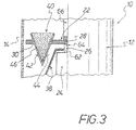
- Figure 3 illustrates an embodiment, wherein the drive device 24 formed by a motor is surrounded by a microwave-reflecting cap element 38, so that the food product 40 to be heated, in particular frozen and thawed, is not only on its radially outer side 42 but also on its radial side inside page 44 with microwaves is acted upon in order to bring about uniform and rapid heating, in particular thawing, of the food product 40.
- the cap element 38 can be provided immovably and formed with a smooth surface. Another possibility is that the cap element 38 is provided to be rotatable about the central axis 26 and is designed with a non-smooth, i.e. ribbed, knobbed, corrugated and / or indented surface for the diffusing microwave reflection.
- the food product 40 to be heated has, for example, a conical shape and is inserted into a conformal, dimensionally stable receiving casing body 46.
- the respective dimensionally stable receptacle casing body 46 consists of an edible, tasteless or flavored dough material, so that the food 40 can be eaten together with the receptacle casing body 46 after thawing and removal from the microwave device 10.
- the receptacle casing body 46 can be formed, for example, from a waffle, such as has been used up to now for eating ice cream portions.
- the Figures 1 and 2 also make it clear that the respective microwave radiation source 18 formed by a magnetron is connected to a fan 48 for cooling it.
- the respective microwave radiation source 18 is also fluidically connected to the cylindrical housing jacket 14 by means of a pipe 50; the respective pipeline 50 opens into the interior 34 of the cylindrical furnace housing 14 in a tangentially oriented manner.
- the heat loss generated in the microwave radiation sources 18 is introduced through the pipes 50 into the interior 34 of the cylindrical oven housing 12 in order to heat the moisture generated during the heating, in particular thawing of frozen food items 40 and to remove them from the microwave by means of a suction device 52.
- Suction device 10 The one formed by a fan
- the suction device 52 is arranged on the housing cover 54 of the cylindrical oven housing 12 of the microwave device 10.
- the housing cover 54 is preferably designed with a protective device against leakage radiation, which is designed as a ⁇ / 4 or ⁇ / 2 throttle depending on the furnace load.
- a device housing 56 is indicated by a thin dash-dotted line.
- Figure 2 also illustrates schematically a weighing device 58 which is assigned to the drive device 24.
- a weighing device 58 which is assigned to the drive device 24.
- the weighing device 58 is also suitable for the operation of the microwave device 10 in the event of incorrect loading - for example with ham and cheese toast, potatoes or the like. - to prevent.
- a collecting device 60 which is removably arranged in the furnace housing 12 and serves to collect moisture and / or dirt particles is also shown. After the collecting device 60 has been removed from the furnace housing 12, it can be cleaned in order to remove dirt particles and / or moisture from the collecting device 60. The cleaning can be done manually or automatically, for example by means of a dishwasher.
- the rotary plate 28 is detachably coupled to the drive shaft 62 of the drive device 24 by means of a form-fit connection 64.
- the turntable 28 has a rod-shaped handle 66 with which the turntable 28 can be separated from the positive connection and removed from the furnace housing 12 as soon as the housing cover 52 has been actuated to open the furnace housing 12, ie swiveled open, for example.
Description
Die Erfindung betrifft ein Mikrowellengerät für innerhalb einer kurzen Zeitspanne zu erwärmendes, insbesondere aufzutauendes Gut, insbesondere Nahrungsmittel-Gut.The invention relates to a microwave device for items to be heated, in particular defrosted, in particular food items, to be heated within a short period of time.
Aus der
Der Erfindung liegt die Aufgabe zugrunde, ein Mikrowellengerät der eingangs genannten Art zu schaffen, mit dem es innerhalb einer kurzen Zeitspanne von bspw. ≤ 1 Minute möglich ist, essbares Gut, insbesondere Nahrungsmittel-Gut, zu erwärmen, insbesondere tiefgekühltes, gefrorenes Gut aufzutauen und essbar zu machen.
The invention is based on the object of creating a microwave device of the type mentioned at the beginning with which it is possible within a short period of time of, for example, ≤ 1 minute to heat edible goods, in particular food goods, in particular to thaw and thaw deep-frozen, frozen goods to make edible.
Diese Aufgabe wird erfindungsgemäß durch die Merkmale des Anspruches 1, d.h. dadurch gelöst, dass das Mikrowellengerät ein Ofengehäuse aufweist, an dessen Gehäusemantel wenigstens eine Mikrowellen-Strahlenquelle mittels eines Mikrowellen-Kopplungselementes angekoppelt ist, wobei das Mikrowellen-Kopplungselement vom Gehäusemantel in Umfangsrichtung verteilt wegsteht, und im Ofengehäuse mindestens eine Gut-Halteeinrichtung für das Gut vorgesehen ist, die mittels einer Antriebseinrichtung um eine zentrale Achse drehbar ist, wobei die mindestens eine Gut-Halteeinrichtung von einem Drehteller gebildet ist, der zum positionsgenauen Halten des zu erwärmenden, insbesondere aufzutauenden Guts vorgesehen ist.This object is achieved according to the invention by the features of claim 1, ie in that the microwave device has an oven housing, to the housing jacket of which at least one microwave radiation source is coupled by means of a microwave coupling element, the microwave coupling element projecting away from the housing jacket in a distributed manner in the circumferential direction, and at least one item-holding device for the item is provided in the furnace housing, which can be rotated around a central axis by means of a drive device, the at least one item-holding device being formed by a turntable, which is provided for holding the item to be heated, in particular to be thawed, in a precise position is.
Bei dem erfindungsgemäßen Mikrowellengerät können an den Gehäusemantel bspw. zwei, drei oder vier Mikrowellen-Strahlenquellen mittels zugehöriger Mikrowellen-Kopplungselemente gleichmäßig verteilt angekoppelt sein, so dass sich im Inneren des zylindrischen Ofengehäuses eine gleichmäßige Verteilung der Mikrowellen bei einer optimalen Verwirbelung des Mikrowellenfeldes ergibt.In the case of the microwave device according to the invention, two, three or four microwave radiation sources, for example, can be coupled to the housing jacket by means of associated microwave coupling elements, so that the inside of the cylindrical oven housing is uniformly distributed with optimal swirling of the microwave field.
Im Ofengehäuse können mehr als eine Gut-Halteeinrichtung für zu erwärmendes, insbesondere aufzutauendes Gut vorgesehen sein, die voneinander axial beabstandet sind. Vorzugsweise ist im Ofengehäuse nur eine einzige Gut-Halteeinrichtung für das zu erwärmende, insbesondere aufzutauende Gut vorgesehen, die im Ofengehäuse axial mittig angeordnet und mittels der Antriebseinrichtung um die zentrale Drehachse drehbar ist.In the furnace housing, more than one item holding device can be provided for items to be heated, in particular items to be thawed, which are axially spaced from one another. Preferably, only a single item holding device for the items to be heated, in particular to be thawed, is provided in the furnace housing, which is arranged axially in the center of the furnace housing and can be rotated about the central axis of rotation by means of the drive device.
Zweckmäßig kann es sein, wenn der Gehäusemantel des Ofengehäuses zum Verhindern einer Kondenswasserbildung eine Heizeinrichtung aufweist. Die Heizeinrichtung kann von einer elektrischen Widerstandsheizung gebildet sein, die den Gehäusemantel umgibt. Desgleichen ist es möglich, dass der Gehäusemantel zumindest teilweise aus einem Material besteht, das unter Mikrowellen-Einfluss einen derartigen Wirbelstromverlust aufweist, dass eine Selbsterwärmung bewirkt wird.It can be expedient if the housing jacket of the furnace housing has a heating device to prevent the formation of condensation. The heating device can be formed by an electrical resistance heater which surrounds the housing jacket. It is also possible for the housing jacket to consist at least partially of a material which, under the influence of microwaves, has such an eddy current loss that self-heating is caused.
Bei dem erfindungsgemäßen Mikrowellengerät hat es sich als zweckmäßig erwiesen, wenn der Drehteller zum Bestücken mit zu erwärmendem, insbesondere aufzutauendem Gut aus dem Ofengehäuse entnehmbar ist, so dass der Drehteller von außerhalb des Mikrowellengerätes mit zu erwärmendem, insbesondere aufzutauendem Gut bestückt und im bestückten Zustand in das Mikrowellengerät eingesetzt werden kann.In the microwave device according to the invention, it has proven to be useful if the turntable can be removed from the oven housing for loading with items to be heated, in particular defrosted, so that the turntable is equipped with items to be heated, in particular defrosted, from outside the microwave device and in the loaded state the microwave oven can be used.
Der Drehteller ist mit der Antriebseinrichtung vorzugsweise Drehmoment übertragend verbindbar. Das kann bspw. durch eine formschlüssige Verbindung, wie eine Feder-Nut-Verbindung, eine Rastzapfen-Verbindung o.dgl., zwischen dem Drehteller und der Antriebseinrichtung realisiert sein.The turntable can be connected to the drive device, preferably in a torque-transmitting manner. This can be implemented, for example, by a positive connection, such as a tongue and groove connection, a locking pin connection or the like, between the turntable and the drive device.
Die jeweilige Mikrowellen-Kopplungseinrichtung ist vorzugsweise von einem Hohlleiter gebildet. Der jeweilige Hohlleiter mündet mit seinem von der zugehörigen Mikrowellen-Strahlenquelle entfernten Ende vorzugsweise tangential in den Gehäusemantel des zylindrischen Ofengehäuses ein.The respective microwave coupling device is preferably formed by a waveguide. The respective waveguide opens with its end remote from the associated microwave radiation source, preferably tangentially, into the housing jacket of the cylindrical furnace housing.
Der Drehteller ist zweckmäßigerweise mit Gut-Haltemitteln ausgebildet, die entlang mindestens eines zur zentralen Achse konzentrischen Teilkreises äquidistant beabstandet vorgesehen sind. Die Gut-Haltemittel können von Löchern, Ausnehmungen, Aussparungen, Schlaufenelementen, Klemmelementen, o.dgl. gebildet sein.The turntable is expediently designed with good holding means, which are provided at an equidistant distance along at least one pitch circle concentric to the central axis. The good holding means can consist of holes, recesses, recesses, loop elements, clamping elements, or the like. be educated.
Der Drehteller kann bspw. vollflächig scheibenförmig mit den Löchern und/oder Ausnehmungen und/oder Aussparungen ausgebildet sein. Eine andere Möglichkeit besteht darin, dass der Drehteller zur Gewichtsreduktion als Steg- oder Rippengebilde mit entsprechenden Löchern, Schlaufenelementen und/oder Klemmelementen gestaltet ist, die durch Steg- oder Rippenränder begrenzt d.h. gebildet sind.The turntable can, for example, be designed in the form of a disk over its entire surface with the holes and / or recesses and / or cutouts. Another possibility is that the turntable is designed as a web or rib structure with corresponding holes, loop elements and / or clamping elements, which are limited, i.e. formed, by web or rib edges to reduce weight.
Der Drehteller kann derart eingerichtet sein, dass das zu erwärmende Gut in eine Bewegung versetzt wird, die nicht eine Rotation um die zentralen Achse darstellt. Diese Vorrichtung kann beispielsweise durch ein Getriebe realisiert sein, das die am Drehteller angeordneten Gut-Haltemittel um von der zentralen Achse abweichende Achsen bewegt.The turntable can be set up in such a way that the item to be heated is set in motion that does not represent a rotation about the central axis. This device can be implemented, for example, by a gear mechanism that moves the goods holding means arranged on the turntable about axes that deviate from the central axis.
Die Gut-Haltemittel sind im Drehteller vorzugsweise entlang mindestens eines zur zentralen Achse konzentrischen Teilkreises gleichmäßig beabstandet vorgesehen. Die im Drehteller ausgebildeten Gut-Haltemittel besitzen lichte Abmessungen, die an das zu erwärmende, insbesondere aufzutauende Gut derartig angepasst sind, dass das Gut, insbesondere Nahrungsmittel-Gut, sich axial definiert durch den Drehteller erstreckt und vom Drehteller definiert, positionsgenau und zuverlässig gehalten wird.The material holding means are provided in the turntable, preferably evenly spaced along at least one pitch circle concentric to the central axis. The goods holding means formed in the turntable have clear dimensions which are adapted to the goods to be heated, in particular thawed, in such a way that the goods, in particular food items, extend axially defined through the turntable and are held in a precise and reliable position by the turntable .
Vorteilhaft kann es sein, wenn die Gut-Haltemittel mit voneinander beabstandeten, partiellen Kontaktflächen ausgebildet sind, um zwischen dem Drehteller und dem zu erwärmenden, insbesondere aufzutauenden Gut eine Ableitung von Dampf und/oder Feuchtigkeit zu ermöglichen. Die partiellen Kontaktflächen können bspw. dadurch realisiert sein, dass der Rand der z.B. durch Löcher gebildeten Gut-Haltemittel gewellt, gezahnt, o.dgl. gestaltet ist.It can be advantageous if the goods holding means are designed with spaced apart, partial contact surfaces in order to allow steam and / or moisture to be dissipated between the turntable and the goods to be heated, in particular to be thawed. The partial contact surfaces can be realized, for example, in that the edge of the material holding means formed e.g. by holes is corrugated, toothed, or the like. is designed.
Der Drehteller besteht vorzugsweise aus einem Mikrowellen-transparenten Material oder aus einem Hybrid, d.h. aus Teilen, die aus einem Mikrowellen leicht ankoppelndem Material bestehen.The turntable is preferably made of a microwave-transparent material or of a hybrid, i.e. of parts which consist of a material that easily couples with microwaves.
Im Drehteller können entlang des mindestens einen Teilkreises bspw. drei bis neun Gut-Haltemittel äquidistant vorgesehen sein.In the turntable, for example, three to nine good holding means can be provided equidistantly along the at least one pitch circle.
Zweckmäßig ist es, wenn im Ofengehäuse zum Sammeln von Feuchtigkeit und/oder Schmutzpartikeln eine Sammeleinrichtung aus Mikrowellen-durchlässigem Material herausnehmbar vorgesehen ist. Die Sammeleinrichtung kann nach dem Herausnehmen aus dem Ofengehäuse manuell oder mit Hilfe einer Geschirrspülmaschine gereinigt, d.h. gewaschen werden.It is useful if a collecting device made of microwave-permeable material is removably provided in the furnace housing for collecting moisture and / or dirt particles. The collecting device, after being removed from the oven housing, can be cleaned, i.e. washed, manually or with the aid of a dishwasher.
Bei dem erfindungsgemäßen Mikrowellengerät ist die Antriebseinrichtung für die mindestens eine Halteeinrichtung vorzugsweise im Bereich des Bodens des Ofengehäuses angeordnet. Der Boden des Ofengehäuses kann mit einer zentralen kappenartigen Aufwölbung ausgebildet sein, durch die unterseitig ein Hohlraum bestimmt ist, in dem die von einem Motor gebildete Antriebseinrichtung vorgesehen ist.In the microwave device according to the invention, the drive device for the at least one holding device is preferably arranged in the area of the bottom of the oven housing. The bottom of the furnace housing can be formed with a central, cap-like bulge, through which a cavity is defined on the underside, in which the drive device formed by a motor is provided.
Die Antriebseinrichtung kann von einem Mikrowellen-reflektierenden Kappenelement umgeben sein, das unbeweglich vorgesehen ist. Bei einer solchen Ausbildung kann das Kappenelement mit einer glatten Oberfläche gestaltet sein. Vorteilhaft kann es jedoch sein, wenn das Kappenelement um die zentrale Achse drehbar vorgesehen und zur zerstreuenden Mikrowellen-Reflexion mit einer nicht glatten, bspw. gerippten, genoppten, gewellten und/oder eingedellten Oberfläche ausgebildet ist. Durch eine solche Ausbildung der zuletzt genannten Art ergibt sich der Vorteil, dass die Mikrowellen an dem Kappenelement nicht nur reflektiert sondern außerdem auch zerstreut werden, so dass die Wirkung der Mikrowellen auf das zu erwärmende, insbesondere aufzutauende Gut, insbesondere Nahrungsmittel-Gut weiter verbessert, d.h. optimiert wird.The drive device can be surrounded by a microwave-reflecting cap element which is provided to be immovable. With such a design, the cap element can be designed with a smooth surface. However, it can be advantageous if the cap element is provided rotatable about the central axis and for the diffusing microwave reflection with a non-smooth, for example ribbed, knobbed, corrugated and / or indented surface is trained. Such a design of the last-mentioned type results in the advantage that the microwaves are not only reflected on the cap element but also scattered, so that the effect of the microwaves on the goods to be heated, in particular to be thawed, in particular food goods, is further improved, ie is optimized.
Mit Hilfe des Mikrowellen-reflektierenden Kappenelementes wird das vom Drehteller definiert, positionsgenau gehaltene Gut nicht nur radial außenseitig sondern mittels des Mikrowellen-reflektierenden Kappenelementes auch an seiner radialen Innenseite mit Mikrowellen beaufschlagt, so dass sich eine gleichmäßige Einwirkung der Mikrowellen auf das Gut und somit optimale Erwärmungsinsbesondere Auftau-Eigenschaften für das Gut ergeben.With the help of the microwave-reflective cap element, the item held by the turntable and held precisely in position is not only exposed to microwaves radially on the outside, but also on its radial inner side by means of the microwave-reflective cap element, so that the microwaves have an even effect on the item and thus optimal Warming, in particular, thawing properties for the goods.
Erfindungsgemäß kann das Ofengehäuse zylindrisch ausgebildet sein und einen Deckel mit einer Schutzeinrichtung gegen Leckstrahlung aufweisen. Die Schutzeinrichtung kann in Abhängigkeit von der jeweiligen Ofenbeladung bspw. eine λ/4- oder λ/2-Drossel bilden.According to the invention, the furnace housing can be cylindrical and have a cover with a protective device against leakage radiation. The protective device can form a λ / 4 or λ / 2 choke, for example, depending on the respective furnace load.
Wenn im Folgenden von einem zylindrischen Ofengehäuse bzw. einem zylindrischen Gehäusemantel die Rede ist, versteht es sich, dass nicht nur ein kreisrundes glattes Grundflächen-Profil gemeint ist, sondern dass das Grundflächen-Profil auch mehreckig glatt oder wellig gestaltet sein kann.When a cylindrical furnace housing or a cylindrical housing jacket is mentioned in the following, it goes without saying that not only a circular, smooth base profile is meant, but that the base profile can also be polygonal, smooth or wavy.
Um im zylindrischen Ofengehäuse entstehende Feuchtigkeit an dem zu erwärmenden, insbesondere aufzutauenden Gut nicht wirksam werden zu lassen, kann es zweckmäßig sein, wenn der Gehäuse-Deckel eine Absaugeinrichtung aufweist, mit der entstehende Feuchtigkeit aus dem Ofengehäuse abgesaugt und ausgeleitet wird. Die Absaugeinrichtung kann von einem Absaugventilator gebildet sein. Eine andere Möglichkeit besteht darin, dass der Gehäuse-Deckel mit Perforationslöchern ausgebildet ist, so dass die warme Luft im Ofengehäuse nach oben steigt und durch die Perforationslöcher aus dem Ofengehäuse ausströmt.In order not to let moisture develop in the cylindrical furnace housing take effect on the goods to be heated, in particular thawed, it can be useful if the housing cover has a suction device with which the resulting moisture is sucked out of the furnace housing and discharged. The suction device can be formed by a suction fan. Another possibility is that the housing cover is designed with perforation holes so that the warm air rises up in the furnace housing and flows out of the furnace housing through the perforation holes.
Als vorteilhaft hat es sich erwiesen, wenn das Mikrowellen-Gerät zur Feststellung der Beladung der Gut-Halteeinrichtung eine Wägeinrichtung aufweist. Die Wägeinrichtung kann außerdem zur Leistungs-Steuerung des Mikrowellen-Gerätes dienen. Mit Hilfe der Wägeinrichtung ist es in vorteilhafter Weise auch möglich, eine Falschbeladung des erfindungsgemäßen Mikrowellen-Gerätes, z.B. mit Schinken-Käse-Toast, Kartoffeln o.dgl., zu verhindern.It has proven to be advantageous if the microwave device has a weighing device for determining the loading of the goods holding device. The weighing device can also be used to control the power of the microwave device. With the help of the weighing device, it is advantageously also possible to prevent incorrect loading of the microwave device according to the invention, e.g. with ham and cheese toast, potatoes or the like.
Die jeweilige Mikrowellen-Strahlenquelle ist vorzugsweise von einem Magnetron gebildet, an das zur Kühlung ein Ventilator angeschlossen ist, und das jeweilige Magnetron ist vorzugsweise mittels einer Rohrleitung mit dem zylindrischen Gehäusemantel strömungstechnisch verbunden, durch die die im Magnetron erzeugte Verlustwärme in das Innere des zylindrischen Ofengehäuses eingeleitet wird. Dabei kann es zweckmäßig sein, im jeweiligen Strömungskanal eine Filtereinrichtung vorzusehen.The respective microwave radiation source is preferably formed by a magnetron to which a fan is connected for cooling, and the respective magnetron is fluidically connected to the cylindrical housing jacket by means of a pipe, through which the heat loss generated in the magnetron into the interior of the cylindrical furnace housing is initiated. It can be useful to provide a filter device in the respective flow channel.
Eine solche Ausbildung des erfindungsgemäßen Mikrowellengerätes weist den Vorteil auf, dass die Abwärme des jeweiligen Magnetrons mit Hilfe des zugehörigen Ventilators in das Innere des zylindrischen Ofengehäuses eingeleitet werden kann, um die beim Erwärmen, insbesondere Auftauen des Guts, insbesondere Nahrungsmittel-Guts, erzeugte Feuchtigkeit mit der besagten Abwärme zu beaufschlagen und die Feuchtigkeit aus dem Inneren des zylindrischen Ofengehäuses mittels der Absaugeinrichtung abzusaugen und auszuleiten.Such a design of the microwave device according to the invention has the advantage that the waste heat of the respective magnetron can be introduced into the interior of the cylindrical furnace housing with the aid of the associated fan in order to carry the moisture generated during the heating, in particular thawing of the goods, in particular food goods to apply said waste heat and to suck off the moisture from the interior of the cylindrical furnace housing by means of the suction device and to discharge it.
Die jeweilige Rohrleitung, mittels welcher das zugehörige Magnetron mit dem Gehäusemantel strömungstechnisch verbunden ist, mündet in den zylindrischen Gehäusemantel zweckmäßigerweise tangential ein.The respective pipeline, by means of which the associated magnetron is fluidically connected to the housing jacket, expediently opens tangentially into the cylindrical housing jacket.
Verwendung findet das erfindungsgemäße Mikrowellengerät vorzugsweise für zu erwärmendes, insbesondere aufzutauendes Nahrungsmittel-Gut, das eine definierte Gestalt besitzt und das in einen formstabilen Aufnahme-Hüllenkörper eingesetzt, zum Erwärmen, insbesondere Auftauen in das Mikrowellengerät eingebracht wird. Der jeweilige Aufnahme-Hüllenkörper für das zu erwärmende, insbesondere aufzutauende Gut ist vorzugsweise von einem geschmacksneutralen oder einem einen bestimmten Geschmack besitzenden Teigmaterial, insbesondere einer Waffel, wie sie ähnlich z.B. für Speise-Eis verwendet wird, gebildet.The microwave device according to the invention is preferably used for food items to be heated, in particular to be thawed, which have a defined shape and which are inserted into a dimensionally stable receiving casing body for heating, in particular thawing, into the microwave device. The respective receiving shell body for the to be heated, In particular, the goods to be thawed are preferably made up of a tasteless or a particular flavored dough material, in particular a waffle, such as is used in a similar way, for example, for ice cream.
Bei dem genannten Nahrungsmittel-Gut kann es sich bspw. um Gemüse und/oder Obst und/oder Fleisch und/oder Fisch o.dgl. handeln, das breiig und/oder kleinteilig vorbereitet und z.B. in kegelförmiger oder kegelstumpfförmiger Gestalt tiefgefroren z.B. in einem Tiefkühl-Schrank bis zum Verkauf bevorratet und gelagert wird. Entsprechend werden die formstabilen Aufnahme-Hüllenkörper aus dem Teigmaterial bis zur Verwendung, d.h. zur Kombination mit dem tiefgefrorenen Nahrungsmittel-Gut, gelagert. Zum Verkauf wird das tiefgefrorene Nahrungsmittel-Gut in einen passenden formstabilen Aufnahme-Hüllenkörper eingesetzt und anschließend wird der formstabile Aufnahme-Hüllenkörper mit dem in ihn eingesetzten, zu erwärmenden, insbesondere aufzutauenden Nahrungsmittel-Gut mit Hilfe der Gut-Halteeinrichtung in das Mikrowellengerät eingebracht und das Mikrowellengerät eingeschaltet, so dass innerhalb einer kurzen Zeitspanne von z.B. weniger als einer Minute das Nahrungsmittel-Gut mit dem Aufnahme-Hüllenkörper erwärmt, insbesondere aufgetaut wird und zum Verzehr zur Verfügung steht.The mentioned food good can be, for example, vegetables and / or fruit and / or meat and / or fish or the like. that is prepared in pulpy and / or small pieces and, for example, frozen in a conical or truncated cone shape, e.g. in a freezer cabinet until it is sold. Correspondingly, the dimensionally stable receiving casing bodies made from the dough material are stored until they are used, i.e. for combination with the frozen food product. For sale, the frozen food product is inserted into a suitable, dimensionally stable receiving casing body and then the dimensionally stable receiving casing body with the food product to be heated, in particular to be thawed, is inserted into the microwave device with the aid of the product holding device and that Microwave device switched on, so that within a short period of time, for example, less than a minute, the food item with the receptacle casing body is heated, in particular thawed, and is available for consumption.
Das erfindungsgemäße Mikrowellengerät ist bspw. dazu in der Lage, tiefgefrorenes Nahrungsmittel-Gut innerhalb einer kurzen Zeitspanne von ≤ 1 Minute von -20°C auf +80°C zu erhitzen.The microwave device according to the invention is able, for example, to heat frozen food items from -20 ° C. to + 80 ° C. within a short period of 1 minute.
Weitere Einzelheiten, Merkmale und Vorteile ergeben sich aus der nachfolgenden Beschreibung eines in der Zeichnung schematisch dargestellten Ausführungsbeispieles des erfindungsgemäßen Mikrowellengerätes bzw. wesentlicher Einzelheiten desselben, wobei explizit klargestellt werden soll, dass die Größenverhältnisse in axialer und radialer Richtung des Mikrowellengerätes nicht den realen Gegebenheiten entsprechen sondern nur der Verdeutlichung der Erfindung dienen sollen.Further details, features and advantages emerge from the following description of an exemplary embodiment of the microwave device according to the invention shown schematically in the drawing or essential details thereof, whereby it should be explicitly made clear that the size relationships in the axial and radial directions of the microwave device do not correspond to the real conditions are only intended to illustrate the invention.
Es zeigen:
-
Figur 1 eine schematische Ansicht des Mikrowellengerätes in Blickrichtung von oben, -
Figur 2 eine schematische Schnittdarstellung entlang der Schnittlinie II-II inFigur 1 , und -
Figur 3 abschnittweise eine Schnittdarstellung des Mikrowellengerätes - ähnlich dem Schnitt gemäßFigur 2 insbesondere zur Verdeutlichung des Mikrowellen reflektierenden Kappenelementes.
-
Figure 1 a schematic view of the microwave device in the direction of view from above, -
Figure 2 a schematic sectional view along the section line II-II inFigure 1 , and -
Figure 3 a sectional view of the microwave device - similar to the section according to FIGFigure 2 especially to illustrate the microwave reflective cap element.
Wie aus
Es ist für einen Fachmann verständlich, dass jede beliebige Anzahl von Mikrowellen-Strahlenquellen, abhängig von deren Leistung und dem zu beheizenden Raumvolumen zum Einsatz kommen kann.It is understandable for a person skilled in the art that any number of microwave radiation sources can be used, depending on their output and the volume of the room to be heated.
Erfindungsgemäß ist es auch möglich, dass eine Anzahl Mikrowellen-Strahlenquellen 18 mit ihren zugehörigen Mikrowellen-Kopplungselementen 16 axial nicht versetzt sondern in einer gemeinsamen Ebene, in Umfangsrichtung verteilt, angeordnet sind.According to the invention, it is also possible that a number of
Im zylindrischen Ofengehäuse 12 ist eine Gut-Halteeinrichtung 22 axial mittig vorgesehen, die mittels einer Antriebseinrichtung 24 um eine zentrale Achse 26 antreibbar ist.A
Die Gut-Halteeinrichtung 22 weist einen Drehteller 28 auf, der insbesondere zum temporären Halten von zu erwärmendem oder tiefgefrorenem und aufzutauendem Nahrungsmittel-Gut mit Gut-Haltemitteln 30 ausgebildet ist. Die Gut-Haltemittel 30 sind entlang eines zur zentralen Achse 26 konzentrischen Teilkreises 32 äquidistant beabstandet vorgesehen. Bspw. ist der Drehteller 28 mit fünf oder mit sechs Gut-Haltemitteln 30 ausgebildet.The
Die Gut-Haltemittel 30 sind bspw. als Löcher ausgebildet; sie können bspw. auch von Ausnehmungen, Aussparungen, Schlaufenelementen, Klemmelementen o.dgl. gebildet sein.The good holding means 30 are, for example, designed as holes; they can, for example, also of recesses, cutouts, loop elements, clamping elements or the like. be educated.
Die für die von einem Drehteller 28 gebildete Gut-Halteeinrichtung 22 vorgesehene Antriebseinrichtung 24 ist im Bereich des Bodens 36 des zylindrischen Ofengehäuses 12 angeordnet. Zu diesem Zwecke ist der Boden 36 mit einer kappenartigen Aufwölbung 37 ausgebildet.The
Die Antriebseinrichtung 24 ist in dem durch die Aufwölbung 37 oberseitig begrenzten Raum angeordnet.The
Das Kappenelement 38 kann unbeweglich vorgesehen und mit einer glatten Oberfläche ausgebildet sein. Eine andere Möglichkeit besteht darin, dass das Kappenelement 38 um die zentrale Achse 26 drehbar vorgesehen und zur zerstreuenden Mikrowellen-Reflexion mit einer nicht glatten, d.h. gerippten, genoppten, gewellten und/oder eingedellten Oberfläche ausgebildet ist.The
Wie aus
Der Aufnahme-Hüllenkörper 46 kann bspw. von einer Waffel gebildet sein, wie sie bislang zum Verspeisen von Speise-Eisportionen verwendet wird.The
Die
Der Gehäuse-Deckel 54 ist vorzugsweise mit einer Schutzeinrichtung gegen Leckstrahlung ausgebildet, die in Abhängigkeit von der Ofenbeladung als λ/4- oder λ/2-Drossel ausgebildet ist.The
In den
In
Der Drehteller 28 ist mit der Antriebswelle 62 der Antriebseinrichtung 24 mittels einer Formschlussverbindung 64 loslösbar gekoppelt. Der Drehteller 28 weist einen stabförmigen Griff 66 auf, mit dem der Drehteller 28 von der Formschlussverbindung trennbar und aus dem Ofengehäuse 12 entnehmbar ist, sobald der Gehäuse-Deckel 52 zum Öffnen des Ofengehäuses 12 betätigt, d.h. bspw. aufgeschwenkt worden ist.
Claims (13)
- A microwave apparatus (10) comprising:an oven housing (12) to the housing shell (14) of which at least two microwave radiation sources (18) are coupled respectively by means of a microwave coupling element (16), wherein each microwave coupling element (16) protrudes from the housing shell (14) circumferentially spaced, and at least one material holding device (22) for the material (40) to be heated is provided in the oven housing (12) which can be rotated about an axis (26) using a driving device (24), the at least one material holding device (40) being formed by a turntable (28) which is provided for holding the material (40) to be heated, in particular to be thawed, with high position accuracy,characterized in thatthe turntable (28) is formed with material retaining means (30) which are provided equidistantly spaced along at least one divided circle (32) concentric with the central axis (26),in that the material-retaining means (30) are formed by holes, indentations, recesses, loop elements and/or clamping elements,in that the oven housing (12) is cylindrical and has a housing cover (54) with an exhaust device (52),in that the respective microwave radiation sources (18) are formed by magnetrons for the cooling of which fans (48) are provided, in that the magnetrons are fluidically connected to the cylindrical housing shell (14) by means of pipes (50), in that the magnetrons with their microwave coupling elements (16) are provided on the housing shell (14) of the oven housing (12) axially offset with respect to each other, and in that the pipes open into the cylindrical oven housing (14) axially offset with respect to each other.
- The microwave apparatus of claim 1,
characterized in that
three or four microwave radiation sources (18) with their microwave coupling elements (16) are provided on the housing shell (14) of the oven housing (12) axially offset with respect to each other. - The microwave apparatus according to claim 1 or 2
characterized in that
the housing shell (14) of the oven housing (12) comprises a heating device for preventing condensation of water. - The microwave apparatus according to any one of claims 1 to 3,
characterized in that
the oven housing is cylindrical and in that the turntable (28) can be removed from the cylindrical oven housing (12) for loading with material (40) to be heated, in particular material to be thawed. - The microwave apparatus according to any one of claims 1 to 4,
characterized in that
the respective microwave coupling device (16) is formed by a waveguide. - The microwave apparatus of claim 1,
characterized in that
the material-retaining means (30) define surfaces for partial contact spaced apart from each other in order to allow steam and/or moisture to be discharged between the turntable (28) and the material (40) to be heated, in particular to be thawed. - The microwave apparatus according to any one of claims 1 to 6,
characterized in that
a collecting device (60) made of microwave-permeable material is removably provided in the oven housing (12) for collecting moisture and/or dirt particles. - The microwave apparatus according to any one of claims 1 to 7,
characterized in that
the driving device (24) provided for the at least one holding device (22) is arranged in the region of the bottom (36) of the cylindrical oven housing (12). - The microwave apparatus of claim 8,
characterized in that
the driving device (24) is surrounded by a microwave-reflecting cap element (38), and/or
the microwave apparatus (10) has a weighing device (58) for determining the loading of the material-holding device (30). - The microwave apparatus of claim 9,
characterized in that
the cap element (38) is stationary and/or
the cap element (38) is provided rotatably about the central axis (26) and is formed with a non-smooth, ribbed, nubbed, corrugated and/or dented surface for scattered microwave reflection. - The microwave apparatus according to any one of claims 1 to 10,
characterized in that
the housing cover (54) has a protection device against stray radiation. - Use of the microwave apparatus according to any one of the preceding claims for food material (40) to be heated, in particular to be thawed, which has a defined shape and which, being inserted into a matching receiving enveloping body (46), is introduced into the microwave apparatus (10) for heating, in particular thawing.
- The use according to claim 12, wherein the respective receiving enveloping body (46) for the material (40) to be heated, in particular to be thawed, is formed by a tasteless dough material or a dough material having a specific taste, in particular a wafer.
Priority Applications (3)
| Application Number | Priority Date | Filing Date | Title |
|---|---|---|---|
| EP15201322.3A EP3182798B1 (en) | 2015-12-18 | 2015-12-18 | Microwave device |
| PCT/EP2016/079546 WO2017102374A1 (en) | 2015-12-18 | 2016-12-02 | Microwave device |
| US16/063,095 US20200323050A1 (en) | 2015-12-18 | 2016-12-02 | Microwave device |
Applications Claiming Priority (1)
| Application Number | Priority Date | Filing Date | Title |
|---|---|---|---|
| EP15201322.3A EP3182798B1 (en) | 2015-12-18 | 2015-12-18 | Microwave device |
Publications (2)
| Publication Number | Publication Date |
|---|---|
| EP3182798A1 EP3182798A1 (en) | 2017-06-21 |
| EP3182798B1 true EP3182798B1 (en) | 2021-03-31 |
Family
ID=54979483
Family Applications (1)
| Application Number | Title | Priority Date | Filing Date |
|---|---|---|---|
| EP15201322.3A Active EP3182798B1 (en) | 2015-12-18 | 2015-12-18 | Microwave device |
Country Status (3)
| Country | Link |
|---|---|
| US (1) | US20200323050A1 (en) |
| EP (1) | EP3182798B1 (en) |
| WO (1) | WO2017102374A1 (en) |
Citations (5)
| Publication number | Priority date | Publication date | Assignee | Title |
|---|---|---|---|---|
| EP0190430A1 (en) * | 1985-01-25 | 1986-08-13 | Societe Des Produits Nestle S.A. | Method and arrangement for heating foodstuffs |
| WO2004046628A2 (en) * | 2002-11-15 | 2004-06-03 | Kiyoshi Matsuda | Structure of a drying appratus for living goods and method for controlling the appratus |
| WO2013046718A1 (en) * | 2011-09-30 | 2013-04-04 | パナソニック株式会社 | High-frequency heating device with electrothermic heating device |
| EP2854478A1 (en) * | 2013-09-27 | 2015-04-01 | Anton Paar GmbH | Microwave heating system |
| US20150093308A1 (en) * | 2013-09-27 | 2015-04-02 | Anton Paar Gmbh | Device for Supporting Reaction Vessels in a Microwave Heating Apparatus |
Family Cites Families (5)
| Publication number | Priority date | Publication date | Assignee | Title |
|---|---|---|---|---|
| US3745291A (en) * | 1972-02-18 | 1973-07-10 | Raytheon Co | Microwave heating applicator |
| JPH0973981A (en) * | 1995-09-05 | 1997-03-18 | Hitachi Home Tec Ltd | High-frequency heating device |
| US5990466A (en) * | 1998-04-02 | 1999-11-23 | Turbochef Technologies, Inc. | Apparatus for supplying microwave energy to a cavity |
| DE19738882C1 (en) | 1997-06-27 | 1998-12-10 | Linn High Therm Gmbh | Continuous oven with microwave heat sources |
| WO2006128212A1 (en) * | 2005-06-03 | 2006-12-07 | Ipv Pty Limited | Improvements in an apparatus for heating a food product |
-
2015
- 2015-12-18 EP EP15201322.3A patent/EP3182798B1/en active Active
-
2016
- 2016-12-02 US US16/063,095 patent/US20200323050A1/en not_active Abandoned
- 2016-12-02 WO PCT/EP2016/079546 patent/WO2017102374A1/en active Application Filing
Patent Citations (5)
| Publication number | Priority date | Publication date | Assignee | Title |
|---|---|---|---|---|
| EP0190430A1 (en) * | 1985-01-25 | 1986-08-13 | Societe Des Produits Nestle S.A. | Method and arrangement for heating foodstuffs |
| WO2004046628A2 (en) * | 2002-11-15 | 2004-06-03 | Kiyoshi Matsuda | Structure of a drying appratus for living goods and method for controlling the appratus |
| WO2013046718A1 (en) * | 2011-09-30 | 2013-04-04 | パナソニック株式会社 | High-frequency heating device with electrothermic heating device |
| EP2854478A1 (en) * | 2013-09-27 | 2015-04-01 | Anton Paar GmbH | Microwave heating system |
| US20150093308A1 (en) * | 2013-09-27 | 2015-04-02 | Anton Paar Gmbh | Device for Supporting Reaction Vessels in a Microwave Heating Apparatus |
Also Published As
| Publication number | Publication date |
|---|---|
| EP3182798A1 (en) | 2017-06-21 |
| US20200323050A1 (en) | 2020-10-08 |
| WO2017102374A1 (en) | 2017-06-22 |
Similar Documents
| Publication | Publication Date | Title |
|---|---|---|
| DE4027555C2 (en) | Microwave cooker with food stirring mechanism - with mixing bowl, stirrer, cover and blade of heat resistant plastics and independently movable into or out of oven | |
| EP3197325B1 (en) | Modular sieve and juicing apparatus. | |
| DE202018006409U1 (en) | Cooking device and components thereof | |
| DE60208152T2 (en) | SHEAF CONTAINER | |
| DE2141434A1 (en) | Method and device for cooking food | |
| EP3182798B1 (en) | Microwave device | |
| EP3513696B1 (en) | Kitchen appliance with a cover element for a preparation vessel | |
| DE102010044630A1 (en) | Method and device for producing pureed food | |
| DE202007013714U1 (en) | Ice crusher for an icemaker | |
| EP0113900A1 (en) | Apparatus and method for the treatment of food with microwaves | |
| DE2707216A1 (en) | DEVICE AND METHOD FOR MIXING MATERIAL | |
| EP2887847B1 (en) | Oven | |
| DE1757892B2 (en) | MICROWAVE OVEN | |
| DE602004007463T2 (en) | Microwave oven provided with a separate cooking chamber | |
| EP3756840A1 (en) | Cutting system for cutting fruit or vegetables into spiral garlands | |
| DE4333096C2 (en) | Device for grating or grating food | |
| DE2541718A1 (en) | DEVICE FOR COOKING Lumpy FOOD | |
| WO2017102993A1 (en) | Device for cutting at least one piece of frozen food | |
| DE3134000C2 (en) | High frequency heating device | |
| DE112020005197T5 (en) | Conveyor Blower | |
| CN107927591B (en) | Method for making crisp meat | |
| DE2841625C2 (en) | Device for chopping food, in particular fruit and vegetables | |
| EP2608709B1 (en) | Device with reduced static and slide friction | |
| EP0700262A1 (en) | Working chamber for an electrically operated domestic kitchen appliance | |
| DE202018002322U1 (en) | cooking machine |
Legal Events
| Date | Code | Title | Description |
|---|---|---|---|
| PUAI | Public reference made under article 153(3) epc to a published international application that has entered the european phase |
Free format text: ORIGINAL CODE: 0009012 |
|
| STAA | Information on the status of an ep patent application or granted ep patent |
Free format text: STATUS: THE APPLICATION HAS BEEN PUBLISHED |
|
| AK | Designated contracting states |
Kind code of ref document: A1 Designated state(s): AL AT BE BG CH CY CZ DE DK EE ES FI FR GB GR HR HU IE IS IT LI LT LU LV MC MK MT NL NO PL PT RO RS SE SI SK SM TR |
|
| AX | Request for extension of the european patent |
Extension state: BA ME |
|
| STAA | Information on the status of an ep patent application or granted ep patent |
Free format text: STATUS: REQUEST FOR EXAMINATION WAS MADE |
|
| 17P | Request for examination filed |
Effective date: 20171214 |
|
| RBV | Designated contracting states (corrected) |
Designated state(s): AL AT BE BG CH CY CZ DE DK EE ES FI FR GB GR HR HU IE IS IT LI LT LU LV MC MK MT NL NO PL PT RO RS SE SI SK SM TR |
|
| RAP1 | Party data changed (applicant data changed or rights of an application transferred) |
Owner name: TASTE & TECH S.R.O. |
|
| STAA | Information on the status of an ep patent application or granted ep patent |
Free format text: STATUS: EXAMINATION IS IN PROGRESS |
|
| 17Q | First examination report despatched |
Effective date: 20190930 |
|
| GRAP | Despatch of communication of intention to grant a patent |
Free format text: ORIGINAL CODE: EPIDOSNIGR1 |
|
| STAA | Information on the status of an ep patent application or granted ep patent |
Free format text: STATUS: GRANT OF PATENT IS INTENDED |
|
| RIC1 | Information provided on ipc code assigned before grant |
Ipc: H05B 6/64 20060101AFI20200929BHEP |
|
| INTG | Intention to grant announced |
Effective date: 20201019 |
|
| GRAS | Grant fee paid |
Free format text: ORIGINAL CODE: EPIDOSNIGR3 |
|
| GRAA | (expected) grant |
Free format text: ORIGINAL CODE: 0009210 |
|
| STAA | Information on the status of an ep patent application or granted ep patent |
Free format text: STATUS: THE PATENT HAS BEEN GRANTED |
|
| AK | Designated contracting states |
Kind code of ref document: B1 Designated state(s): AL AT BE BG CH CY CZ DE DK EE ES FI FR GB GR HR HU IE IS IT LI LT LU LV MC MK MT NL NO PL PT RO RS SE SI SK SM TR |
|
| REG | Reference to a national code |
Ref country code: GB Ref legal event code: FG4D Free format text: NOT ENGLISH Ref country code: CH Ref legal event code: EP |
|
| REG | Reference to a national code |
Ref country code: DE Ref legal event code: R096 Ref document number: 502015014463 Country of ref document: DE Ref country code: AT Ref legal event code: REF Ref document number: 1378440 Country of ref document: AT Kind code of ref document: T Effective date: 20210415 |
|
| REG | Reference to a national code |
Ref country code: IE Ref legal event code: FG4D Free format text: LANGUAGE OF EP DOCUMENT: GERMAN |
|
| REG | Reference to a national code |
Ref country code: LT Ref legal event code: MG9D |
|
| PG25 | Lapsed in a contracting state [announced via postgrant information from national office to epo] |
Ref country code: HR Free format text: LAPSE BECAUSE OF FAILURE TO SUBMIT A TRANSLATION OF THE DESCRIPTION OR TO PAY THE FEE WITHIN THE PRESCRIBED TIME-LIMIT Effective date: 20210331 Ref country code: FI Free format text: LAPSE BECAUSE OF FAILURE TO SUBMIT A TRANSLATION OF THE DESCRIPTION OR TO PAY THE FEE WITHIN THE PRESCRIBED TIME-LIMIT Effective date: 20210331 Ref country code: NO Free format text: LAPSE BECAUSE OF FAILURE TO SUBMIT A TRANSLATION OF THE DESCRIPTION OR TO PAY THE FEE WITHIN THE PRESCRIBED TIME-LIMIT Effective date: 20210630 Ref country code: BG Free format text: LAPSE BECAUSE OF FAILURE TO SUBMIT A TRANSLATION OF THE DESCRIPTION OR TO PAY THE FEE WITHIN THE PRESCRIBED TIME-LIMIT Effective date: 20210630 |
|
| PG25 | Lapsed in a contracting state [announced via postgrant information from national office to epo] |
Ref country code: SE Free format text: LAPSE BECAUSE OF FAILURE TO SUBMIT A TRANSLATION OF THE DESCRIPTION OR TO PAY THE FEE WITHIN THE PRESCRIBED TIME-LIMIT Effective date: 20210331 Ref country code: LV Free format text: LAPSE BECAUSE OF FAILURE TO SUBMIT A TRANSLATION OF THE DESCRIPTION OR TO PAY THE FEE WITHIN THE PRESCRIBED TIME-LIMIT Effective date: 20210331 Ref country code: RS Free format text: LAPSE BECAUSE OF FAILURE TO SUBMIT A TRANSLATION OF THE DESCRIPTION OR TO PAY THE FEE WITHIN THE PRESCRIBED TIME-LIMIT Effective date: 20210331 |
|
| REG | Reference to a national code |
Ref country code: NL Ref legal event code: MP Effective date: 20210331 |
|
| PG25 | Lapsed in a contracting state [announced via postgrant information from national office to epo] |
Ref country code: CZ Free format text: LAPSE BECAUSE OF FAILURE TO SUBMIT A TRANSLATION OF THE DESCRIPTION OR TO PAY THE FEE WITHIN THE PRESCRIBED TIME-LIMIT Effective date: 20210331 Ref country code: EE Free format text: LAPSE BECAUSE OF FAILURE TO SUBMIT A TRANSLATION OF THE DESCRIPTION OR TO PAY THE FEE WITHIN THE PRESCRIBED TIME-LIMIT Effective date: 20210331 Ref country code: LT Free format text: LAPSE BECAUSE OF FAILURE TO SUBMIT A TRANSLATION OF THE DESCRIPTION OR TO PAY THE FEE WITHIN THE PRESCRIBED TIME-LIMIT Effective date: 20210331 Ref country code: NL Free format text: LAPSE BECAUSE OF FAILURE TO SUBMIT A TRANSLATION OF THE DESCRIPTION OR TO PAY THE FEE WITHIN THE PRESCRIBED TIME-LIMIT Effective date: 20210331 Ref country code: SM Free format text: LAPSE BECAUSE OF FAILURE TO SUBMIT A TRANSLATION OF THE DESCRIPTION OR TO PAY THE FEE WITHIN THE PRESCRIBED TIME-LIMIT Effective date: 20210331 |
|
| PG25 | Lapsed in a contracting state [announced via postgrant information from national office to epo] |
Ref country code: IS Free format text: LAPSE BECAUSE OF FAILURE TO SUBMIT A TRANSLATION OF THE DESCRIPTION OR TO PAY THE FEE WITHIN THE PRESCRIBED TIME-LIMIT Effective date: 20210731 Ref country code: PT Free format text: LAPSE BECAUSE OF FAILURE TO SUBMIT A TRANSLATION OF THE DESCRIPTION OR TO PAY THE FEE WITHIN THE PRESCRIBED TIME-LIMIT Effective date: 20210802 Ref country code: PL Free format text: LAPSE BECAUSE OF FAILURE TO SUBMIT A TRANSLATION OF THE DESCRIPTION OR TO PAY THE FEE WITHIN THE PRESCRIBED TIME-LIMIT Effective date: 20210331 Ref country code: SK Free format text: LAPSE BECAUSE OF FAILURE TO SUBMIT A TRANSLATION OF THE DESCRIPTION OR TO PAY THE FEE WITHIN THE PRESCRIBED TIME-LIMIT Effective date: 20210331 Ref country code: RO Free format text: LAPSE BECAUSE OF FAILURE TO SUBMIT A TRANSLATION OF THE DESCRIPTION OR TO PAY THE FEE WITHIN THE PRESCRIBED TIME-LIMIT Effective date: 20210331 |
|
| REG | Reference to a national code |
Ref country code: DE Ref legal event code: R097 Ref document number: 502015014463 Country of ref document: DE |
|
| PG25 | Lapsed in a contracting state [announced via postgrant information from national office to epo] |
Ref country code: DK Free format text: LAPSE BECAUSE OF FAILURE TO SUBMIT A TRANSLATION OF THE DESCRIPTION OR TO PAY THE FEE WITHIN THE PRESCRIBED TIME-LIMIT Effective date: 20210331 Ref country code: AL Free format text: LAPSE BECAUSE OF FAILURE TO SUBMIT A TRANSLATION OF THE DESCRIPTION OR TO PAY THE FEE WITHIN THE PRESCRIBED TIME-LIMIT Effective date: 20210331 Ref country code: ES Free format text: LAPSE BECAUSE OF FAILURE TO SUBMIT A TRANSLATION OF THE DESCRIPTION OR TO PAY THE FEE WITHIN THE PRESCRIBED TIME-LIMIT Effective date: 20210331 |
|
| PLBE | No opposition filed within time limit |
Free format text: ORIGINAL CODE: 0009261 |
|
| STAA | Information on the status of an ep patent application or granted ep patent |
Free format text: STATUS: NO OPPOSITION FILED WITHIN TIME LIMIT |
|
| 26N | No opposition filed |
Effective date: 20220104 |
|
| PG25 | Lapsed in a contracting state [announced via postgrant information from national office to epo] |
Ref country code: IS Free format text: LAPSE BECAUSE OF FAILURE TO SUBMIT A TRANSLATION OF THE DESCRIPTION OR TO PAY THE FEE WITHIN THE PRESCRIBED TIME-LIMIT Effective date: 20210731 |
|
| REG | Reference to a national code |
Ref country code: DE Ref legal event code: R119 Ref document number: 502015014463 Country of ref document: DE |
|
| PG25 | Lapsed in a contracting state [announced via postgrant information from national office to epo] |
Ref country code: MC Free format text: LAPSE BECAUSE OF FAILURE TO SUBMIT A TRANSLATION OF THE DESCRIPTION OR TO PAY THE FEE WITHIN THE PRESCRIBED TIME-LIMIT Effective date: 20210331 Ref country code: IT Free format text: LAPSE BECAUSE OF FAILURE TO SUBMIT A TRANSLATION OF THE DESCRIPTION OR TO PAY THE FEE WITHIN THE PRESCRIBED TIME-LIMIT Effective date: 20210331 |
|
| REG | Reference to a national code |
Ref country code: CH Ref legal event code: PL |
|
| GBPC | Gb: european patent ceased through non-payment of renewal fee |
Effective date: 20211218 |
|
| REG | Reference to a national code |
Ref country code: BE Ref legal event code: MM Effective date: 20211231 |
|
| PG25 | Lapsed in a contracting state [announced via postgrant information from national office to epo] |
Ref country code: LU Free format text: LAPSE BECAUSE OF NON-PAYMENT OF DUE FEES Effective date: 20211218 Ref country code: IE Free format text: LAPSE BECAUSE OF NON-PAYMENT OF DUE FEES Effective date: 20211218 Ref country code: GB Free format text: LAPSE BECAUSE OF NON-PAYMENT OF DUE FEES Effective date: 20211218 Ref country code: DE Free format text: LAPSE BECAUSE OF NON-PAYMENT OF DUE FEES Effective date: 20220701 |
|
| PG25 | Lapsed in a contracting state [announced via postgrant information from national office to epo] |
Ref country code: FR Free format text: LAPSE BECAUSE OF NON-PAYMENT OF DUE FEES Effective date: 20211231 Ref country code: BE Free format text: LAPSE BECAUSE OF NON-PAYMENT OF DUE FEES Effective date: 20211231 |
|
| PG25 | Lapsed in a contracting state [announced via postgrant information from national office to epo] |
Ref country code: LI Free format text: LAPSE BECAUSE OF NON-PAYMENT OF DUE FEES Effective date: 20211231 Ref country code: CH Free format text: LAPSE BECAUSE OF NON-PAYMENT OF DUE FEES Effective date: 20211231 |
|
| REG | Reference to a national code |
Ref country code: AT Ref legal event code: MM01 Ref document number: 1378440 Country of ref document: AT Kind code of ref document: T Effective date: 20211218 |
|
| PG25 | Lapsed in a contracting state [announced via postgrant information from national office to epo] |
Ref country code: AT Free format text: LAPSE BECAUSE OF NON-PAYMENT OF DUE FEES Effective date: 20211218 |
|
| PG25 | Lapsed in a contracting state [announced via postgrant information from national office to epo] |
Ref country code: HU Free format text: LAPSE BECAUSE OF FAILURE TO SUBMIT A TRANSLATION OF THE DESCRIPTION OR TO PAY THE FEE WITHIN THE PRESCRIBED TIME-LIMIT; INVALID AB INITIO Effective date: 20151218 |
|
| PG25 | Lapsed in a contracting state [announced via postgrant information from national office to epo] |
Ref country code: CY Free format text: LAPSE BECAUSE OF FAILURE TO SUBMIT A TRANSLATION OF THE DESCRIPTION OR TO PAY THE FEE WITHIN THE PRESCRIBED TIME-LIMIT Effective date: 20210331 |
|
| PG25 | Lapsed in a contracting state [announced via postgrant information from national office to epo] |
Ref country code: GR Free format text: LAPSE BECAUSE OF FAILURE TO SUBMIT A TRANSLATION OF THE DESCRIPTION OR TO PAY THE FEE WITHIN THE PRESCRIBED TIME-LIMIT Effective date: 20210331 |