EP3181911A1 - Kantenberandung eines rotationselements und gebläserad - Google Patents
Kantenberandung eines rotationselements und gebläserad Download PDFInfo
- Publication number
- EP3181911A1 EP3181911A1 EP16195358.3A EP16195358A EP3181911A1 EP 3181911 A1 EP3181911 A1 EP 3181911A1 EP 16195358 A EP16195358 A EP 16195358A EP 3181911 A1 EP3181911 A1 EP 3181911A1
- Authority
- EP
- European Patent Office
- Prior art keywords
- impeller
- blades
- fan
- fan wheel
- edge
- Prior art date
- Legal status (The legal status is an assumption and is not a legal conclusion. Google has not performed a legal analysis and makes no representation as to the accuracy of the status listed.)
- Granted
Links
Images

Classifications
-
- F—MECHANICAL ENGINEERING; LIGHTING; HEATING; WEAPONS; BLASTING
- F04—POSITIVE - DISPLACEMENT MACHINES FOR LIQUIDS; PUMPS FOR LIQUIDS OR ELASTIC FLUIDS
- F04D—NON-POSITIVE-DISPLACEMENT PUMPS
- F04D29/00—Details, component parts, or accessories
- F04D29/26—Rotors specially for elastic fluids
- F04D29/28—Rotors specially for elastic fluids for centrifugal or helico-centrifugal pumps for radial-flow or helico-centrifugal pumps
- F04D29/30—Vanes
-
- F—MECHANICAL ENGINEERING; LIGHTING; HEATING; WEAPONS; BLASTING
- F04—POSITIVE - DISPLACEMENT MACHINES FOR LIQUIDS; PUMPS FOR LIQUIDS OR ELASTIC FLUIDS
- F04D—NON-POSITIVE-DISPLACEMENT PUMPS
- F04D29/00—Details, component parts, or accessories
- F04D29/26—Rotors specially for elastic fluids
- F04D29/28—Rotors specially for elastic fluids for centrifugal or helico-centrifugal pumps for radial-flow or helico-centrifugal pumps
- F04D29/281—Rotors specially for elastic fluids for centrifugal or helico-centrifugal pumps for radial-flow or helico-centrifugal pumps for fans or blowers
-
- F—MECHANICAL ENGINEERING; LIGHTING; HEATING; WEAPONS; BLASTING
- F05—INDEXING SCHEMES RELATING TO ENGINES OR PUMPS IN VARIOUS SUBCLASSES OF CLASSES F01-F04
- F05D—INDEXING SCHEME FOR ASPECTS RELATING TO NON-POSITIVE-DISPLACEMENT MACHINES OR ENGINES, GAS-TURBINES OR JET-PROPULSION PLANTS
- F05D2240/00—Components
- F05D2240/20—Rotors
- F05D2240/30—Characteristics of rotor blades, i.e. of any element transforming dynamic fluid energy to or from rotational energy and being attached to a rotor
- F05D2240/303—Characteristics of rotor blades, i.e. of any element transforming dynamic fluid energy to or from rotational energy and being attached to a rotor related to the leading edge of a rotor blade
-
- F—MECHANICAL ENGINEERING; LIGHTING; HEATING; WEAPONS; BLASTING
- F05—INDEXING SCHEMES RELATING TO ENGINES OR PUMPS IN VARIOUS SUBCLASSES OF CLASSES F01-F04
- F05D—INDEXING SCHEME FOR ASPECTS RELATING TO NON-POSITIVE-DISPLACEMENT MACHINES OR ENGINES, GAS-TURBINES OR JET-PROPULSION PLANTS
- F05D2250/00—Geometry
- F05D2250/70—Shape
Definitions
- the invention relates to an edging edge of a rotary element of an air movement device, in particular an impeller, for reducing the particle adhesion. Furthermore, the invention relates to an impeller for fans with a special fan blade contour to reduce the particle adhesion to the impeller and in particular the impeller blades during operation.
- impellers have been optimized in terms of their geometry and in particular with respect to the blade design to perform the air duct with high efficiency with low noise. In the course of operation, however, particles such as dust or lint may adhere, which have a negative effect on these parameters.
- the invention further forms known air movement devices, in particular impellers, in terms of their geometry.
- the invention is therefore based on the object of providing an edge boundary of a rotary element which minimizes particle adhesion during operation.
- an impeller is to be provided which has an impeller geometry which minimizes particulate adhesion during operation.
- an edge boundary of a rotary element of an air movement device in particular an impeller
- the rotation element has an axial extent parallel to the axis of rotation and promotes an air volume during operation.
- a freestanding edge of the air movement device is defined, which interacts with the moving air volume during operation.
- Part of the invention is the use of the above-described edge boundary on at least one edge of the impeller blades of the impeller.
- the edge preferably faces an inlet side of the impeller and determines the blade contour.
- n defines a scattering corridor and lies in a value range 3 ⁇ n ⁇ 1/3, d a diameter of the impeller and c a variable number.
- x is in a range d ⁇ x ⁇ d / 50.
- variable c does not influence the curve shape of the blade contour, but exclusively determines the height of the blade contour pointing to the inlet side on the ordinate in the coordinate system.
- the value for c is therefore arbitrary.
- the specific inlet side blade contour of the fan blades creates a flow that reduces particle adhesion during operation by 25-50%.
- the impeller blades have the blade contour over at least 40% of their total extent in the radial direction. Due to the special contour over such a substantial part of the fan blade length, the particle adhesion is effectively reduced. In addition, an embodiment is advantageous in which the impeller blades have the blade contour at least in a radially inner portion which extends radially outwardly from its radially inner end.
- the impeller blades are curved in the circumferential direction at least in one direction, in particular arcuate.
- a radial extent of the impeller blades, this applies to curved impeller blades the extent in the radial direction and circumferential direction from radially inward to radially outward.
- the impeller has a hub extending conically in the axial direction to the inlet side, to which the impeller blades radially adjoin.
- the tapered hub and the fan wheel blades are thus in fluidic operative connection.
- the impeller preferably has a bottom disk, on which the impeller blades are integrally formed.
- the bottom disk and the hub are in the radial direction directly and flush with each other.
- the bottom plate sets in one embodiment the conical extent of the hub continues and even has an axial increase in the radially inwardly adjacent to the hub area.
- the impeller blades are provided in one embodiment only in the area of the bottom disk.
- one of the bottom disk axially opposite cover disk is arranged on the impeller, wherein the impeller blades extend axially between the bottom disk and the cover disk and form the corresponding distance.
- the cover disc extends in both the radial and axial directions and in one embodiment forms an axial inlet opening with an inner opening edge.
- the impeller blades extend in an axial plan view in the radial direction inwardly beyond the opening edge.
- the diameter of the inlet opening is so large that the fan wheel blades project radially inwardly beyond the opening edge when looking into the inlet opening. This is associated with the fact that the diameter of the inlet opening is greater than the diameter of the hub.
- the particular blade contour determined by the formula is provided in particular in the region which extends inward in the radial direction beyond the opening edge of the inlet opening.
- an embodiment of the impeller is favorable, in which an axial extension of the impeller blades at its respective radial inner end flows smoothly into a surface of the bottom disk.
- the impeller blades become axially shorter and shorter radially inward until they are flush with the bottom disk.
- the curve shape of the blade contour of the fan wheel blades defined by the formula is provided in the region of the inlet opening. The particle adhesion in the radially inner region is thereby significantly reduced.
- the cost of materials and therefore the required adhesion surface by the Blower shovels minimal.
- the impeller blades have at their respective radial outer edge portion their maximum axial extent and terminate flush with outer edges of the bottom plate and / or the cover plate.
- the impeller is in one piece and in particular made of plastic. As a result, both the number of parts and the assembly costs are reduced.
- the invention also includes a fan with an impeller with the technical features described above.
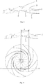
- FIG. 1 and 2 is an embodiment of an inventive Fan wheel 1 with an edge edge according to the invention of the fan wheel blades 2 in a perspective view and a plan view shown.
- the impeller 1 is integrally formed with the bottom plate 6 and the cover plate 7, which are connected by the axially extending and circumferentially curved impeller blades 2.
- the bottom plate 6 and the cover plate 7 terminate flush with the radial outer edges of the impeller blades 2 and form the diameter d of the impeller 1.
- the cover plate 7 has an inner opening edge 9, which determines the size of the axial inlet opening 8 of the impeller 1.
- the fan wheel blades 2 extend in the axial plan view FIG. 2 seen in the radial direction inwardly beyond the opening edge 9 also.
- the corresponding shape of the fan wheel blades 2 begins, starting from its radially inner end 4 in the direction radially outward.
- the tapered in the axial direction hub 5 is also arranged, which merges at the hub edge 10 in the bottom plate 6.
- the impeller blades 2 close to the hub 5 spaced apart in the radial direction.
- FIG. 3 shows a partially broken radial section AA of the impeller Fig. 1 and Fig. 4 , wherein the cover plate 7 has been removed to illustrate the blade contour 3 with the edge boundary of the fan wheel blades 2 according to the above formula in the radially inner portion.
- the blade contour 3 of the fan wheel blades 2 extends substantially continuously in the axial direction as far as the radial outer edge.
- the End of the blade contour 3 with the edge boundary of the fan wheel blades 2 according to the above-mentioned formula seen in the radial direction forms the tip 21, which forms the transition to the substantially continuously axially falling blade contour 3.
- the radially inner free ends 4 of the impeller blades 2 flow over into the surface of the bottom disk 6.
- FIG. 4 is a representation for better comprehensibility of the blade contour 3 with the edge boundary of the impeller blades 2 according to the above formula seen in projection to the impeller from Fig. 1 ,
- the edge boundary determined by the formula runs in the embodiment shown along the blade contour 3 over a projected length R.
- the impeller 1 shown achieves a reduction in particle adhesion of over 30% in measurements with respect to the blower wheel known from the prior art under identical environmental conditions.
- the invention is not limited in its execution to the above-mentioned preferred embodiments. Rather, a number of variants is conceivable, which makes use of the illustrated solution even with fundamentally different types of use. For example, seen in an axial plan view S-shaped impeller blades can be used.
Landscapes
- Engineering & Computer Science (AREA)
- Mechanical Engineering (AREA)
- General Engineering & Computer Science (AREA)
- Structures Of Non-Positive Displacement Pumps (AREA)
Abstract
Description
- Die Erfindung betrifft eine Kantenberandung eines Rotationselements einer Luftbewegungseinrichtung, insbesondere eines Gebläserades, zur Reduzierung der Partikelanhaftung. Ferner betrifft die Erfindung ein Gebläserad für Ventilatoren mit einer speziellen Gebläseradschaufelkontur zur Reduzierung der Partikelanhaftung an dem Gebläserad und insbesondere den Gebläseradschaufeln im Betrieb.
- Gattungsbildende Gebläseräder sind aus dem Stand der Technik bekannt und beispielsweise in der Druckschrift
EP 2 366 907 A2 offenbart. - Derartige Gebläseräder wurden hinsichtlich ihrer Geometrie und insbesondere bezüglich der Schaufelausbildung dahingehend optimiert, die Luftführung mit hoher Effizienz bei geringer Geräuschbildung durchzuführen. Im Laufe des Betriebs kann es jedoch zur Anhaftung von Partikeln, wie Staub oder Flusen kommen, die sich negativ auf diese Parameter auswirken.
- Die Erfindung bildet bekannte Luftbewegungseinrichtungen, insbesondere Laufräder nun hinsichtlich ihrer Geometrie weiter. Der Erfindung liegt deshalb die Aufgabe zugrunde, eine Kanteberandung eines Rotationselements bereit zu stellen, die eine Partikelanhaftung im Betrieb minimiert. Zudem soll ein Gebläserad bereitgestellt werden, das eine Gebläseradschaufelgeometrie aufweist, die eine Partikelanhaftung im Betrieb minimiert.
- Diese Aufgaben werden durch die Merkmalskombinationen gemäß der Patentansprüche 1 und 4 gelöst.
- Erfindungsgemäß wird eine Kantenberandung eines Rotationselements einer Luftbewegungseinrichtung, insbesondere eines Gebläserades, vorgeschlagen. Das Rotationselement weist eine axiale Erstreckung parallel zur Rotationsachse auf und fördert im Betrieb ein Luftvolumen. Die Kantenberandung ist derart geometrisch ausgebildet, dass sie durch die Formel

- Als Kantenberandung ist eine freistehende Kante der Luftbewegungseinrichtung definiert, die im Betrieb mit dem bewegten Luftvolumen wechselwirkt.
- Bestandteil der Erfindung ist die Verwendung der vorstehend beschriebenen Kantenberandung an zumindest einer Kante der Gebläseradschaufeln des Gebläserades. Die Kante weist vorzugsweise zu einer Einlassseite des Gebläserades und bestimmt die Schaufelkontur.
- Ferner umfasst die Erfindung ein Gebläserad mit einer axialen Einlassseite sowie mehreren in Umfangsrichtung beabstandet angeordneten und sich zumindest abschnittsweise in radialer Richtung erstreckenden Gebläseradschaufeln, die im Radialschnitt gesehen jeweils zumindest teilweise eine sich nach radial außen hin vergrößernde und zur Einlassseite weisende Schaufelkontur aufweisen, deren Kantenberandung durch die Formel

- Die Variable c beeinflusst den Kurvenverlauf der Schaufelkontur nicht, sondern bestimmt ausschließlich die Höhe der zur Einlassseite weisenden Schaufelkontur an der Ordinate im Koordinatensystem. Der Wert für c ist deshalb beliebig wählbar.
- Durch den Wertebereich für den Parameter n wird ein Korridor zweier Kurvenverläufe aufgespannt, innerhalb dessen der Kurvenverlauf der Schaufelkontur liegt.
- Die spezifische zur Einlassseite weisende Schaufelkontur der Gebläseradschaufeln erzeugt eine Strömung, welche die Partikelanhaftung im Betrieb um 25-50% reduziert. Ausschlaggebend hierfür ist unter anderem die geringe Axialerstreckung der Gebläseradschaufeln im radial innen liegenden Abschnitt mit der spezifisch formelgemäß geschwungenen Vergrößerung in Richtung nach radial außen.
- In einer vorteilhaften Ausführungsvariante ist vorgesehen, dass die Gebläseradschaufeln die Schaufelkontur über zumindest 40% ihrer Gesamterstreckung in radialer Richtung aufweisen. Durch den speziellen Konturverlauf über einen derart wesentlichen Teil der Gebläseradschaufellänge wird die Partikelanhaftung wirkungsvoll reduziert. Zudem ist eine Ausführung vorteilhaft, bei der die Gebläseradschaufeln die Schaufelkontur zumindest in einem radial innen liegenden Abschnitt aufweisen, der sich ausgehend von ihrem radial innen liegenden Ende aus radial auswärts erstreckt.
- In einer Weiterbildung ist vorgesehen, dass die Gebläseradschaufeln in Umfangsrichtung zumindest in eine Richtung gekrümmt, insbesondere bogenförmig ausgebildet sind. Soweit vorliegend auf eine "radiale Erstreckung" der Gebläseradschaufeln Bezug genommen wird, betrifft diese bei gekrümmten Gebläseradschaufeln die Erstreckung in radialer Richtung und Umfangsrichtung von radial innen nach radial außen.
- Bei einer Ausführungsform weist das Gebläserad eine in axialer Richtung konisch zur Einlassseite verlaufende Nabe auf, an die sich die Gebläseradschaufeln radial beabstandet anschließen. Die konisch zulaufende Nabe und die Gebläseradschaufeln stehen somit in strömungstechnischer Wirkverbindung.
- Zudem weist das Gebläserad vorzugsweise eine Bodenscheibe auf, auf der die Gebläseradschaufeln einstückig ausgebildet sind. Die Bodenscheibe und die Nabe gehen in radialer Richtung unmittelbar und bündig ineinander über. Zudem setzt die Bodenscheibe in einer Ausführungsform die konische Erstreckung der Nabe fort und weist selbst eine Axialerhöhung im radial innen an die Nabe angrenzenden Bereich auf. Die Gebläseradschaufeln werden in einem Ausführungsbeispiel nur im Bereich der Bodenscheibe vorgesehen.
- In einer Weiterbildung wird an dem Gebläserad eine der Bodenscheibe axial gegenüberliegende Deckscheibe angeordnet, wobei sich zwischen Bodenscheibe und Deckscheibe die Gebläseradschaufeln axial erstrecken und den entsprechenden Abstand bilden. Die Deckscheibe erstreckt sich sowohl in radialer als auch in axialer Richtung und bildet in einer Ausführungsform eine axiale Einlassöffnung mit einem inneren Öffnungsrand. Vorteilhaft ist dann eine Ausführung, bei der sich die Gebläseradschaufeln in einer axialen Draufsicht in radialer Richtung einwärts über den Öffnungsrand hinaus erstrecken. In anderen Worten ist der Durchmesser der Einlassöffnung so groß, dass die Gebläseradschaufeln bei einem Blick in die Einlassöffnung über den Öffnungsrand radial einwärts überstehen. Damit einhergehend ist, dass der Durchmesser der Einlassöffnung größer ist als der Durchmesser der Nabe. Die spezielle durch die Formel bestimmte Schaufelkontur ist insbesondere in dem Bereich vorgesehen, der sich in radialer Richtung einwärts über den Öffnungsrand der Einlassöffnung hinaus erstreckt.
- Ferner ist eine Ausführungsvariante des Gebläserades günstig, bei der eine Axialerstreckung der Gebläseradschaufeln an ihrem jeweiligen radialen inneren Ende fließend in eine Oberfläche der Bodenscheibe übergeht. Die Gebläseradschaufeln werden dabei nach radial innen axial immer kürzer, bis sie mit der Bodenscheibe abschließen. Dabei wird der durch die Formel definierte Kurvenverlauf der Schaufelkontur der Gebläseradschaufeln im Bereich der Einlassöffnung vorgesehen. Die Partikelanhaftung in radial innen liegenden Bereich ist dadurch deutlich reduziert. Zudem ist der Materialaufwand und mithin die gebotene Anhaftungsfläche durch die Gebläseradschaufeln minimal.
- In einer weiteren Ausführungsvariante ist vorgesehen, dass die Gebläseradschaufeln an ihrem jeweiligen radialen Außenrandabschnitt ihre maximale Axialerstreckung aufweisen und mit Außenkanten der Bodenscheibe und/oder der Deckscheibe bündig abschließen.
- In einer vorteilhaften Variante ist das Gebläserad einteilig und insbesondere aus Kunststoff ausgebildet. Hierdurch sind sowohl die Teileanzahl und der Montageaufwand reduziert.
- Die Erfindung umfasst zudem einen Ventilator mit einem Gebläserad mit den vorstehend beschriebenen technischen Merkmalen.
- Alle offenbarten Merkmale sind beliebig kombinierbar soweit dies technisch möglich ist.
- Andere vorteilhafte Weiterbildungen der Erfindung sind in den Unteransprüchen gekennzeichnet bzw. werden nachstehend zusammen mit der Beschreibung der bevorzugten Ausführung der Erfindung anhand der Figuren näher dargestellt. Es zeigen:
- Fig. 1
- eine perspektivische Ansicht eines erfindungsgemäßen Gebläserades;
- Fig. 2
- eine Draufsicht auf das Gebläserad aus
Fig. 1 ; - Fig. 3
- eine teilweise aufgebrochene seitliche Schnittansicht des Gebläserades aus
Fig. 1 ; - Fig. 4
- eine Darstellung der Schaufelkontur in Projektion zum Gebläserad aus
Fig. 1 . - In den
Figuren 1 und 2 ist ein Ausführungsbeispiel eines erfindungsgemäßen Gebläserades 1 mit einer erfindungsgemäßen Kantenberandung der Gebläseradschaufeln 2 in einer perspektivischen Ansicht und einer Draufsicht dargestellt. Das Gebläserad 1 ist einteilig mit der Bodenscheibe 6 und der Deckscheibe 7 ausgebildet, die durch die sich in axialer Richtung erstreckende und in Umfangsrichtung gekrümmte Gebläseradschaufeln 2 verbunden sind. Die Bodenscheibe 6 und die Deckscheibe 7 schließen bündig mit den radialen Außenkanten der Gebläseradschaufeln 2 ab und bilden den Durchmesser d des Gebläserades 1. Die Deckscheibe 7 weist einen inneren Öffnungsrand 9 auf, der die Größe der axialen Einlassöffnung 8 des Gebläserades 1 bestimmt. Die Gebläseradschaufeln 2 erstrecken sich in der axialen Draufsicht ausFigur 2 gesehen in radialer Richtung einwärts über den Öffnungsrand 9 hinaus. - Die Gebläseradschaufeln 2 weisen jeweils eine zur Einlassseite weisende Schaufelkontur 3 auf, die eine Kantenberandung geometrisch geformt nach der oben genannten Formel mit Werten n=1, 11≤x≤33 und c=0 bestimmt. Die entsprechende Form der Gebläseradschaufeln 2 beginnt ausgehend von ihrem radial innen liegenden Ende 4 in Richtung radial auswärts. An dem Gebläserad 1 ist zudem die in axialer Richtung konisch zulaufende Nabe 5 angeordnet, die am Nabenrand 10 in die Bodenscheibe 6 übergeht. Die Gebläseradschaufeln 2 schließen sich in radialer Richtung beabstandet an die Nabe 5 an.
-
Figur 3 zeigt einen teilweise aufgebrochenen Radialschnitt A-A des Gebläserades ausFig. 1 undFig. 4 , wobei die Deckscheibe 7 entfernt wurde, um die Schaufelkontur 3 mit der Kantenberandung der Gebläseradschaufeln 2 gemäß der vorstehend genannten Formel im radial inneren Abschnitt zu verdeutlichen. In dem sich in radialer Richtung anschließenden Bereich, der von der Deckscheibe 7 vollständig überdeckt wird, verläuft die Schaufelkontur 3 der Gebläseradschaufeln 2 bis zum radialen Außenrand im Wesentlichen stetig in axialer Richtung fallend. Das Ende der Schaufelkontur 3 mit der Kantenberandung der Gebläseradschaufeln 2 gemäß der vorstehend genannten Formel in radialer Richtung gesehen bildet die Spitze 21, die gleichzeitig den Übergang zu der im Wesentlichen stetig axial fallenden Schaufelkontur 3 bildet. Die radial innen liegenden freien Enden 4 der Gebläseradschaufeln 2 gehen fließend in die Oberfläche der Bodenscheibe 6 über. -
Figur 4 ist eine Darstellung zur besseren Erfassbarkeit der Schaufelkontur 3 mit der Kantenberandung der Gebläseradschaufeln 2 gemäß der vorstehend genannten Formel in Projektion gesehen zum Gebläserad ausFig. 1 . Die durch die Formel bestimmte Kantenberandung verläuft im gezeigten Ausführungsbeispiel entlang der Schaufelkontur 3 über eine projizierte Länge R. Das gezeigte Gebläserad 1 erzielt bei Messungen gegenüber dem aus dem Stand der Technik bekannten Gebläserad bei identischen Umgebungsbedingungen eine Reduzierung der Partikelanhaftung von über 30%. - Die Erfindung beschränkt sich in ihrer Ausführung nicht auf die vorstehend angegebenen bevorzugten Ausführungsbeispiele. Vielmehr ist eine Anzahl von Varianten denkbar, welche von der dargestellten Lösung auch bei grundsätzlich anders gearteten Ausführungen Gebrauch macht. Beispielsweise können auch in einer axialen Draufsicht gesehen S-förmige Gebläseradschaufeln verwendet werden.
Claims (15)
- Kantenberandung eines Rotationselements einer Luftbewegungseinrichtung mit einem Durchmesser d, insbesondere eines Gebläserades, wobei das Rotationselement eine Erstreckung in einer axialen Richtung parallel zu einer Rotationsachse aufweist und die Kantenberandung im Querschnitt gesehen eine geometrische Form aufweist, die durch die Formel

- Verwendung einer Kantenberandung nach Anspruch 1 an zumindest einer Kante einer Gebläseradschaufel (2) eines Gebläserades.
- Verwendung der Kantenberandung nach Anspruch 2, dadurch gekennzeichnet, dass die Kante zu einer Einlassseite des Gebläserades weist und eine Schaufelkontur (3) bestimmt.
- Gebläserad mit einer axialen Einlassseite sowie mehreren in Umfangsrichtung beabstandet angeordneten und sich zumindest abschnittsweise in radialer Richtung erstreckenden Gebläseradschaufeln (2), die im Radialschnitt gesehen jeweils zumindest teilweise eine sich nach radial außen hin vergrößernde und zur Einlassseite weisende Schaufelkontur (3) aufweisen, die eine Kantenberandung mit der geometrischen Form nach Anspruch 1 aufweist.
- Gebläserad nach Anspruch 4, dadurch gekennzeichnet, dass die Gebläseradschaufeln die Schaufelkontur (3) über zumindest 40% ihrer Gesamterstreckung in radialer Richtung aufweisen.
- Gebläserad nach Anspruch 4 oder 5, dadurch gekennzeichnet, dass die Gebläseradschaufeln (2) die Schaufelkontur (3) zumindest in einem radial innen liegenden Abschnitt aufweisen, der sich ausgehend von ihrem radial innen liegenden Ende (4) aus radial auswärts erstreckt.
- Gebläserad nach zumindest einem der vorigen Ansprüche 4 bis 6, dadurch gekennzeichnet, dass die Gebläseradschaufeln (2) in Umfangsrichtung zumindest in eine Richtung gekrümmt ausgebildet sind.
- Gebläserad nach zumindest einem der vorigen Ansprüche 4 bis 7, dadurch gekennzeichnet, dass es eine in axialer Richtung konisch verlaufende Nabe (5) aufweist, an die sich die Gebläseradschaufeln (2) radial beabstandet anschließen.
- Gebläserad nach zumindest einem der vorigen Ansprüche 4 bis 8, dadurch gekennzeichnet, dass es eine Bodenscheibe (6) aufweist, auf der die Gebläseradschaufeln (2) einstückig ausgebildet sind.
- Gebläserad nach zumindest einem der vorigen Ansprüche 4 bis 9, dadurch gekennzeichnet, dass es eine Deckscheibe (7) aufweist, welche die Gebläseradschaufeln (2) zumindest abschnittsweise überdeckt.
- Gebläserad nach dem vorigen Anspruch, dadurch gekennzeichnet, dass die Deckscheibe (7) eine axiale Einlassöffnung (8) mit einem inneren Öffnungsrand (9) aufweist und sich die Gebläseradschaufeln (2) in einer axialen Draufsicht in radialer Richtung einwärts über den Öffnungsrand (9) hinaus erstrecken.
- Gebläserad nach zumindest einem der vorigen Ansprüche 9 bis 11, dadurch gekennzeichnet, dass eine Axialerstreckung der Gebläseradschaufeln (2) an ihrem jeweiligen radialen inneren Ende (4) fließend in eine Oberfläche der Bodenscheibe (6) übergeht.
- Gebläserad nach zumindest einem der vorigen Ansprüche, dadurch gekennzeichnet, dass es einteilig ausgebildet ist.
- Gebläserad nach zumindest einem der vorigen Ansprüche 5 bis 9, dadurch gekennzeichnet, dass die Gebläseradschaufeln (2) an ihrem jeweiligen radialen Außenrandabschnitt ihre maximale Axialerstreckung aufweisen und mit radialen Außenkanten der Bodenscheibe (6) und/oder der Deckscheibe (7) bündig abschließen.
- Ventilator mit einem Gebläserad nach zumindest einem der Ansprüche 4 bis 14.
Priority Applications (2)
| Application Number | Priority Date | Filing Date | Title |
|---|---|---|---|
| RS20210934A RS62268B1 (sr) | 2015-12-17 | 2016-10-24 | Dizajn ivica rotacionog elementa i radnog kola ventilatora |
| PL16195358T PL3181911T3 (pl) | 2015-12-17 | 2016-10-24 | Obramowanie krawędziowe elementu rotacyjnego i koło dmuchawy |
Applications Claiming Priority (1)
| Application Number | Priority Date | Filing Date | Title |
|---|---|---|---|
| DE102015122132.2A DE102015122132A1 (de) | 2015-12-17 | 2015-12-17 | Kantenberandung eines Rotationselements und Gebläserad |
Publications (2)
| Publication Number | Publication Date |
|---|---|
| EP3181911A1 true EP3181911A1 (de) | 2017-06-21 |
| EP3181911B1 EP3181911B1 (de) | 2021-06-02 |
Family
ID=57189949
Family Applications (1)
| Application Number | Title | Priority Date | Filing Date |
|---|---|---|---|
| EP16195358.3A Active EP3181911B1 (de) | 2015-12-17 | 2016-10-24 | Kantenberandung eines rotationselements und gebläserad |
Country Status (8)
| Country | Link |
|---|---|
| US (1) | US11136990B2 (de) |
| EP (1) | EP3181911B1 (de) |
| CN (1) | CN205806012U (de) |
| DE (1) | DE102015122132A1 (de) |
| ES (1) | ES2881635T3 (de) |
| HU (1) | HUE055784T2 (de) |
| PL (1) | PL3181911T3 (de) |
| RS (1) | RS62268B1 (de) |
Cited By (1)
| Publication number | Priority date | Publication date | Assignee | Title |
|---|---|---|---|---|
| WO2022062130A1 (zh) * | 2020-09-28 | 2022-03-31 | 广东美的制冷设备有限公司 | 离心风轮和具有其的空气处理设备 |
Families Citing this family (3)
| Publication number | Priority date | Publication date | Assignee | Title |
|---|---|---|---|---|
| USD949315S1 (en) * | 2016-06-24 | 2022-04-19 | Ebm-Papst Mulfingen Gmbh & Co. Kg | Vane damper with trailing edge |
| AU2019253039A1 (en) * | 2018-04-12 | 2020-12-03 | Resource West, Inc. | Impeller for ambient water evaporators, and related system and method |
| CN121520239A (zh) | 2024-08-13 | 2026-02-13 | 台达电子工业股份有限公司 | 风扇叶轮 |
Citations (7)
| Publication number | Priority date | Publication date | Assignee | Title |
|---|---|---|---|---|
| GB517293A (en) * | 1938-07-19 | 1940-01-25 | Victor Vladimirovitch Dibovsky | Improvements in or relating to rotary blowers |
| GB710391A (en) * | 1952-06-11 | 1954-06-09 | Howden James & Co Ltd | Improvements in radial flow impellers |
| FR1295593A (fr) * | 1961-04-29 | 1962-06-08 | Snecma | Perfectionnements aux machines tournantes augmentant la pression d'un fluide, notamment aux pompes et compresseurs centrifuges et hélico-centrifuges |
| DE9303711U1 (de) * | 1993-03-13 | 1993-05-13 | Babcock-BSH AG vormals Büttner-Schilde-Haas AG, 4150 Krefeld | Radiallaufrad |
| CN201513380U (zh) * | 2009-10-19 | 2010-06-23 | 浙江双阳风机有限公司 | 一种核电厂核岛大气监测离心风机的叶轮 |
| EP2366907A2 (de) | 2010-03-15 | 2011-09-21 | ebm-papst Mulfingen GmbH & Co. KG | Radial-Lüfterrad-Anordnung |
| CN203230624U (zh) * | 2013-04-08 | 2013-10-09 | 合肥晶弘电器有限公司 | 离心式风扇转子、离心式风扇及风冷冰箱 |
Family Cites Families (7)
| Publication number | Priority date | Publication date | Assignee | Title |
|---|---|---|---|---|
| DE879588C (de) * | 1951-07-22 | 1953-06-15 | Babcock & Wilcox Dampfkessel W | Geblaese fuer staubhaltige Gase |
| KR100355827B1 (ko) * | 2000-08-17 | 2002-11-07 | 엘지전자 주식회사 | 창문형 에어컨의 터보팬 |
| JP4700414B2 (ja) * | 2005-06-02 | 2011-06-15 | 本田技研工業株式会社 | 空冷内燃機関用多翼ファン |
| EP2143958A1 (de) * | 2008-07-07 | 2010-01-13 | Josip Pavetic | In einem Rohr eingebundener Lüfter |
| US20100071877A1 (en) * | 2008-09-19 | 2010-03-25 | Nitin Goel | Reducing accumulation of dust particles on a heat dissipating arrangement |
| JP5287772B2 (ja) * | 2010-03-16 | 2013-09-11 | 株式会社デンソー | 遠心式多翼ファン |
| WO2015160850A1 (en) * | 2014-04-14 | 2015-10-22 | Enevor Inc. | Conical impeller and applications thereof |
-
2015
- 2015-12-17 DE DE102015122132.2A patent/DE102015122132A1/de not_active Withdrawn
-
2016
- 2016-07-07 CN CN201620714893.0U patent/CN205806012U/zh active Active
- 2016-10-24 RS RS20210934A patent/RS62268B1/sr unknown
- 2016-10-24 PL PL16195358T patent/PL3181911T3/pl unknown
- 2016-10-24 ES ES16195358T patent/ES2881635T3/es active Active
- 2016-10-24 HU HUE16195358A patent/HUE055784T2/hu unknown
- 2016-10-24 EP EP16195358.3A patent/EP3181911B1/de active Active
- 2016-11-16 US US15/353,046 patent/US11136990B2/en active Active
Patent Citations (7)
| Publication number | Priority date | Publication date | Assignee | Title |
|---|---|---|---|---|
| GB517293A (en) * | 1938-07-19 | 1940-01-25 | Victor Vladimirovitch Dibovsky | Improvements in or relating to rotary blowers |
| GB710391A (en) * | 1952-06-11 | 1954-06-09 | Howden James & Co Ltd | Improvements in radial flow impellers |
| FR1295593A (fr) * | 1961-04-29 | 1962-06-08 | Snecma | Perfectionnements aux machines tournantes augmentant la pression d'un fluide, notamment aux pompes et compresseurs centrifuges et hélico-centrifuges |
| DE9303711U1 (de) * | 1993-03-13 | 1993-05-13 | Babcock-BSH AG vormals Büttner-Schilde-Haas AG, 4150 Krefeld | Radiallaufrad |
| CN201513380U (zh) * | 2009-10-19 | 2010-06-23 | 浙江双阳风机有限公司 | 一种核电厂核岛大气监测离心风机的叶轮 |
| EP2366907A2 (de) | 2010-03-15 | 2011-09-21 | ebm-papst Mulfingen GmbH & Co. KG | Radial-Lüfterrad-Anordnung |
| CN203230624U (zh) * | 2013-04-08 | 2013-10-09 | 合肥晶弘电器有限公司 | 离心式风扇转子、离心式风扇及风冷冰箱 |
Cited By (1)
| Publication number | Priority date | Publication date | Assignee | Title |
|---|---|---|---|---|
| WO2022062130A1 (zh) * | 2020-09-28 | 2022-03-31 | 广东美的制冷设备有限公司 | 离心风轮和具有其的空气处理设备 |
Also Published As
| Publication number | Publication date |
|---|---|
| US20170175777A1 (en) | 2017-06-22 |
| HUE055784T2 (hu) | 2021-12-28 |
| PL3181911T3 (pl) | 2021-11-29 |
| RS62268B1 (sr) | 2021-09-30 |
| DE102015122132A1 (de) | 2017-06-22 |
| CN205806012U (zh) | 2016-12-14 |
| US11136990B2 (en) | 2021-10-05 |
| EP3181911B1 (de) | 2021-06-02 |
| ES2881635T3 (es) | 2021-11-30 |
Similar Documents
| Publication | Publication Date | Title |
|---|---|---|
| EP3308030B1 (de) | Strömungsleitgitter zur anordnung an einem ventilator | |
| DE112013002698T5 (de) | Luftgebläse | |
| EP2418389A2 (de) | Flügelrad für einen Ventilator | |
| DE102010009566A9 (de) | Radial- oder Diagonal-Ventilatorrad | |
| DE69817526T2 (de) | Axiallüfter | |
| EP3181911B1 (de) | Kantenberandung eines rotationselements und gebläserad | |
| DE102015107907A1 (de) | Ebenes Strömungsleitgitter | |
| EP2466150A2 (de) | Flügelrad für einen Ventilator sowie Verfahren zur Herstellung eines solchen Flügelrades | |
| EP3034886A1 (de) | Schaufel und lüfterlaufrad damit | |
| DE102013106679A1 (de) | Gebläsebaugruppe | |
| EP3256732B1 (de) | Ventilatorrad und ventilator | |
| EP3475580B1 (de) | Gebläseradscheibe und gebläserad | |
| DE102016107656A1 (de) | Schaufelkantengeometrie einer Schaufel eines Luftförderrads | |
| DE102014219058A1 (de) | Radialverdichterlaufrad und zugehöriger Radialverdichter | |
| EP3368774B1 (de) | Ventilatorrad und ventilator | |
| DE202015106910U1 (de) | Kantenberandung eines Rotationselements und Gebläserad | |
| DE102007016805B4 (de) | Axialventilator, insbesondere für die Kühlanlage eines Schienenfahrzeuges | |
| DE102013020628B4 (de) | Laufrad eines Axialventilator | |
| WO2018158260A1 (de) | Lüfterrad | |
| DE202015100654U1 (de) | Ventilatorrad und Ventilator | |
| WO2011110468A1 (de) | Gebläsemodul | |
| AT17059U1 (de) | Axiallüfter | |
| DE10249244B4 (de) | Laufrad für eine Seitenkanalmaschine | |
| EP3770510B1 (de) | Gebläse für eine dunstabzugsvorrichtung und kombinationsgerät | |
| DE102024204335A1 (de) | Verbindungsanordnung für einen Luftführungskanal |
Legal Events
| Date | Code | Title | Description |
|---|---|---|---|
| PUAI | Public reference made under article 153(3) epc to a published international application that has entered the european phase |
Free format text: ORIGINAL CODE: 0009012 |
|
| STAA | Information on the status of an ep patent application or granted ep patent |
Free format text: STATUS: THE APPLICATION HAS BEEN PUBLISHED |
|
| AK | Designated contracting states |
Kind code of ref document: A1 Designated state(s): AL AT BE BG CH CY CZ DE DK EE ES FI FR GB GR HR HU IE IS IT LI LT LU LV MC MK MT NL NO PL PT RO RS SE SI SK SM TR |
|
| AX | Request for extension of the european patent |
Extension state: BA ME |
|
| STAA | Information on the status of an ep patent application or granted ep patent |
Free format text: STATUS: REQUEST FOR EXAMINATION WAS MADE |
|
| 17P | Request for examination filed |
Effective date: 20171208 |
|
| RBV | Designated contracting states (corrected) |
Designated state(s): AL AT BE BG CH CY CZ DE DK EE ES FI FR GB GR HR HU IE IS IT LI LT LU LV MC MK MT NL NO PL PT RO RS SE SI SK SM TR |
|
| STAA | Information on the status of an ep patent application or granted ep patent |
Free format text: STATUS: EXAMINATION IS IN PROGRESS |
|
| 17Q | First examination report despatched |
Effective date: 20200421 |
|
| GRAP | Despatch of communication of intention to grant a patent |
Free format text: ORIGINAL CODE: EPIDOSNIGR1 |
|
| STAA | Information on the status of an ep patent application or granted ep patent |
Free format text: STATUS: GRANT OF PATENT IS INTENDED |
|
| INTG | Intention to grant announced |
Effective date: 20210129 |
|
| GRAS | Grant fee paid |
Free format text: ORIGINAL CODE: EPIDOSNIGR3 |
|
| GRAA | (expected) grant |
Free format text: ORIGINAL CODE: 0009210 |
|
| STAA | Information on the status of an ep patent application or granted ep patent |
Free format text: STATUS: THE PATENT HAS BEEN GRANTED |
|
| REG | Reference to a national code |
Ref country code: CH Ref legal event code: EP |
|
| AK | Designated contracting states |
Kind code of ref document: B1 Designated state(s): AL AT BE BG CH CY CZ DE DK EE ES FI FR GB GR HR HU IE IS IT LI LT LU LV MC MK MT NL NO PL PT RO RS SE SI SK SM TR |
|
| REG | Reference to a national code |
Ref country code: GB Ref legal event code: FG4D Free format text: NOT ENGLISH |
|
| REG | Reference to a national code |
Ref country code: AT Ref legal event code: REF Ref document number: 1398710 Country of ref document: AT Kind code of ref document: T Effective date: 20210615 |
|
| REG | Reference to a national code |
Ref country code: IE Ref legal event code: FG4D Free format text: LANGUAGE OF EP DOCUMENT: GERMAN |
|
| REG | Reference to a national code |
Ref country code: DE Ref legal event code: R096 Ref document number: 502016013129 Country of ref document: DE |
|
| REG | Reference to a national code |
Ref country code: SE Ref legal event code: TRGR |
|
| REG | Reference to a national code |
Ref country code: LT Ref legal event code: MG9D |
|
| PG25 | Lapsed in a contracting state [announced via postgrant information from national office to epo] |
Ref country code: FI Free format text: LAPSE BECAUSE OF FAILURE TO SUBMIT A TRANSLATION OF THE DESCRIPTION OR TO PAY THE FEE WITHIN THE PRESCRIBED TIME-LIMIT Effective date: 20210602 Ref country code: LT Free format text: LAPSE BECAUSE OF FAILURE TO SUBMIT A TRANSLATION OF THE DESCRIPTION OR TO PAY THE FEE WITHIN THE PRESCRIBED TIME-LIMIT Effective date: 20210602 Ref country code: BG Free format text: LAPSE BECAUSE OF FAILURE TO SUBMIT A TRANSLATION OF THE DESCRIPTION OR TO PAY THE FEE WITHIN THE PRESCRIBED TIME-LIMIT Effective date: 20210902 Ref country code: HR Free format text: LAPSE BECAUSE OF FAILURE TO SUBMIT A TRANSLATION OF THE DESCRIPTION OR TO PAY THE FEE WITHIN THE PRESCRIBED TIME-LIMIT Effective date: 20210602 |
|
| REG | Reference to a national code |
Ref country code: NL Ref legal event code: MP Effective date: 20210602 |
|
| PG25 | Lapsed in a contracting state [announced via postgrant information from national office to epo] |
Ref country code: LV Free format text: LAPSE BECAUSE OF FAILURE TO SUBMIT A TRANSLATION OF THE DESCRIPTION OR TO PAY THE FEE WITHIN THE PRESCRIBED TIME-LIMIT Effective date: 20210602 Ref country code: GR Free format text: LAPSE BECAUSE OF FAILURE TO SUBMIT A TRANSLATION OF THE DESCRIPTION OR TO PAY THE FEE WITHIN THE PRESCRIBED TIME-LIMIT Effective date: 20210903 Ref country code: NO Free format text: LAPSE BECAUSE OF FAILURE TO SUBMIT A TRANSLATION OF THE DESCRIPTION OR TO PAY THE FEE WITHIN THE PRESCRIBED TIME-LIMIT Effective date: 20210902 |
|
| REG | Reference to a national code |
Ref country code: ES Ref legal event code: FG2A Ref document number: 2881635 Country of ref document: ES Kind code of ref document: T3 Effective date: 20211130 |
|
| REG | Reference to a national code |
Ref country code: HU Ref legal event code: AG4A Ref document number: E055784 Country of ref document: HU |
|
| PG25 | Lapsed in a contracting state [announced via postgrant information from national office to epo] |
Ref country code: NL Free format text: LAPSE BECAUSE OF FAILURE TO SUBMIT A TRANSLATION OF THE DESCRIPTION OR TO PAY THE FEE WITHIN THE PRESCRIBED TIME-LIMIT Effective date: 20210602 Ref country code: PT Free format text: LAPSE BECAUSE OF FAILURE TO SUBMIT A TRANSLATION OF THE DESCRIPTION OR TO PAY THE FEE WITHIN THE PRESCRIBED TIME-LIMIT Effective date: 20211004 Ref country code: RO Free format text: LAPSE BECAUSE OF FAILURE TO SUBMIT A TRANSLATION OF THE DESCRIPTION OR TO PAY THE FEE WITHIN THE PRESCRIBED TIME-LIMIT Effective date: 20210602 Ref country code: SK Free format text: LAPSE BECAUSE OF FAILURE TO SUBMIT A TRANSLATION OF THE DESCRIPTION OR TO PAY THE FEE WITHIN THE PRESCRIBED TIME-LIMIT Effective date: 20210602 Ref country code: SM Free format text: LAPSE BECAUSE OF FAILURE TO SUBMIT A TRANSLATION OF THE DESCRIPTION OR TO PAY THE FEE WITHIN THE PRESCRIBED TIME-LIMIT Effective date: 20210602 Ref country code: EE Free format text: LAPSE BECAUSE OF FAILURE TO SUBMIT A TRANSLATION OF THE DESCRIPTION OR TO PAY THE FEE WITHIN THE PRESCRIBED TIME-LIMIT Effective date: 20210602 |
|
| REG | Reference to a national code |
Ref country code: DE Ref legal event code: R097 Ref document number: 502016013129 Country of ref document: DE |
|
| PLBE | No opposition filed within time limit |
Free format text: ORIGINAL CODE: 0009261 |
|
| STAA | Information on the status of an ep patent application or granted ep patent |
Free format text: STATUS: NO OPPOSITION FILED WITHIN TIME LIMIT |
|
| PG25 | Lapsed in a contracting state [announced via postgrant information from national office to epo] |
Ref country code: DK Free format text: LAPSE BECAUSE OF FAILURE TO SUBMIT A TRANSLATION OF THE DESCRIPTION OR TO PAY THE FEE WITHIN THE PRESCRIBED TIME-LIMIT Effective date: 20210602 |
|
| 26N | No opposition filed |
Effective date: 20220303 |
|
| PG25 | Lapsed in a contracting state [announced via postgrant information from national office to epo] |
Ref country code: AL Free format text: LAPSE BECAUSE OF FAILURE TO SUBMIT A TRANSLATION OF THE DESCRIPTION OR TO PAY THE FEE WITHIN THE PRESCRIBED TIME-LIMIT Effective date: 20210602 |
|
| REG | Reference to a national code |
Ref country code: BE Ref legal event code: MM Effective date: 20211031 |
|
| GBPC | Gb: european patent ceased through non-payment of renewal fee |
Effective date: 20211024 |
|
| PG25 | Lapsed in a contracting state [announced via postgrant information from national office to epo] |
Ref country code: MC Free format text: LAPSE BECAUSE OF FAILURE TO SUBMIT A TRANSLATION OF THE DESCRIPTION OR TO PAY THE FEE WITHIN THE PRESCRIBED TIME-LIMIT Effective date: 20210602 |
|
| PG25 | Lapsed in a contracting state [announced via postgrant information from national office to epo] |
Ref country code: LU Free format text: LAPSE BECAUSE OF NON-PAYMENT OF DUE FEES Effective date: 20211024 Ref country code: GB Free format text: LAPSE BECAUSE OF NON-PAYMENT OF DUE FEES Effective date: 20211024 Ref country code: BE Free format text: LAPSE BECAUSE OF NON-PAYMENT OF DUE FEES Effective date: 20211031 |
|
| PG25 | Lapsed in a contracting state [announced via postgrant information from national office to epo] |
Ref country code: IE Free format text: LAPSE BECAUSE OF NON-PAYMENT OF DUE FEES Effective date: 20211024 |
|
| PG25 | Lapsed in a contracting state [announced via postgrant information from national office to epo] |
Ref country code: CY Free format text: LAPSE BECAUSE OF FAILURE TO SUBMIT A TRANSLATION OF THE DESCRIPTION OR TO PAY THE FEE WITHIN THE PRESCRIBED TIME-LIMIT Effective date: 20210602 |
|
| P01 | Opt-out of the competence of the unified patent court (upc) registered |
Effective date: 20230525 |
|
| PG25 | Lapsed in a contracting state [announced via postgrant information from national office to epo] |
Ref country code: MK Free format text: LAPSE BECAUSE OF FAILURE TO SUBMIT A TRANSLATION OF THE DESCRIPTION OR TO PAY THE FEE WITHIN THE PRESCRIBED TIME-LIMIT Effective date: 20210602 |
|
| PG25 | Lapsed in a contracting state [announced via postgrant information from national office to epo] |
Ref country code: MT Free format text: LAPSE BECAUSE OF FAILURE TO SUBMIT A TRANSLATION OF THE DESCRIPTION OR TO PAY THE FEE WITHIN THE PRESCRIBED TIME-LIMIT Effective date: 20210602 |
|
| REG | Reference to a national code |
Ref country code: CH Ref legal event code: U11 Free format text: ST27 STATUS EVENT CODE: U-0-0-U10-U11 (AS PROVIDED BY THE NATIONAL OFFICE) Effective date: 20251101 |
|
| PGFP | Annual fee paid to national office [announced via postgrant information from national office to epo] |
Ref country code: HU Payment date: 20251020 Year of fee payment: 10 |
|
| PGFP | Annual fee paid to national office [announced via postgrant information from national office to epo] |
Ref country code: DE Payment date: 20251020 Year of fee payment: 10 |
|
| PGFP | Annual fee paid to national office [announced via postgrant information from national office to epo] |
Ref country code: AT Payment date: 20251021 Year of fee payment: 10 |
|
| PGFP | Annual fee paid to national office [announced via postgrant information from national office to epo] |
Ref country code: IT Payment date: 20251031 Year of fee payment: 10 |
|
| PGFP | Annual fee paid to national office [announced via postgrant information from national office to epo] |
Ref country code: FR Payment date: 20251029 Year of fee payment: 10 |
|
| PGFP | Annual fee paid to national office [announced via postgrant information from national office to epo] |
Ref country code: TR Payment date: 20251022 Year of fee payment: 10 |
|
| PGFP | Annual fee paid to national office [announced via postgrant information from national office to epo] |
Ref country code: SE Payment date: 20251023 Year of fee payment: 10 Ref country code: CH Payment date: 20251101 Year of fee payment: 10 |
|
| PGFP | Annual fee paid to national office [announced via postgrant information from national office to epo] |
Ref country code: CZ Payment date: 20251013 Year of fee payment: 10 |
|
| PGFP | Annual fee paid to national office [announced via postgrant information from national office to epo] |
Ref country code: PL Payment date: 20251010 Year of fee payment: 10 |
|
| PGFP | Annual fee paid to national office [announced via postgrant information from national office to epo] |
Ref country code: RS Payment date: 20251015 Year of fee payment: 10 |
|
| PGFP | Annual fee paid to national office [announced via postgrant information from national office to epo] |
Ref country code: ES Payment date: 20251114 Year of fee payment: 10 |