EP3175136B1 - Actionneur de freinage pour véhicule - Google Patents
Actionneur de freinage pour véhicule Download PDFInfo
- Publication number
- EP3175136B1 EP3175136B1 EP15753724.2A EP15753724A EP3175136B1 EP 3175136 B1 EP3175136 B1 EP 3175136B1 EP 15753724 A EP15753724 A EP 15753724A EP 3175136 B1 EP3175136 B1 EP 3175136B1
- Authority
- EP
- European Patent Office
- Prior art keywords
- screw
- rollers
- casing
- thread
- actuator
- Prior art date
- Legal status (The legal status is an assumption and is not a legal conclusion. Google has not performed a legal analysis and makes no representation as to the accuracy of the status listed.)
- Active
Links
Images

Classifications
-
- F—MECHANICAL ENGINEERING; LIGHTING; HEATING; WEAPONS; BLASTING
- F16—ENGINEERING ELEMENTS AND UNITS; GENERAL MEASURES FOR PRODUCING AND MAINTAINING EFFECTIVE FUNCTIONING OF MACHINES OR INSTALLATIONS; THERMAL INSULATION IN GENERAL
- F16D—COUPLINGS FOR TRANSMITTING ROTATION; CLUTCHES; BRAKES
- F16D65/00—Parts or details
- F16D65/14—Actuating mechanisms for brakes; Means for initiating operation at a predetermined position
- F16D65/16—Actuating mechanisms for brakes; Means for initiating operation at a predetermined position arranged in or on the brake
- F16D65/18—Actuating mechanisms for brakes; Means for initiating operation at a predetermined position arranged in or on the brake adapted for drawing members together, e.g. for disc brakes
-
- F—MECHANICAL ENGINEERING; LIGHTING; HEATING; WEAPONS; BLASTING
- F16—ENGINEERING ELEMENTS AND UNITS; GENERAL MEASURES FOR PRODUCING AND MAINTAINING EFFECTIVE FUNCTIONING OF MACHINES OR INSTALLATIONS; THERMAL INSULATION IN GENERAL
- F16D—COUPLINGS FOR TRANSMITTING ROTATION; CLUTCHES; BRAKES
- F16D65/00—Parts or details
- F16D65/14—Actuating mechanisms for brakes; Means for initiating operation at a predetermined position
-
- B—PERFORMING OPERATIONS; TRANSPORTING
- B60—VEHICLES IN GENERAL
- B60T—VEHICLE BRAKE CONTROL SYSTEMS OR PARTS THEREOF; BRAKE CONTROL SYSTEMS OR PARTS THEREOF, IN GENERAL; ARRANGEMENT OF BRAKING ELEMENTS ON VEHICLES IN GENERAL; PORTABLE DEVICES FOR PREVENTING UNWANTED MOVEMENT OF VEHICLES; VEHICLE MODIFICATIONS TO FACILITATE COOLING OF BRAKES
- B60T13/00—Transmitting braking action from initiating means to ultimate brake actuator with power assistance or drive; Brake systems incorporating such transmitting means, e.g. air-pressure brake systems
- B60T13/74—Transmitting braking action from initiating means to ultimate brake actuator with power assistance or drive; Brake systems incorporating such transmitting means, e.g. air-pressure brake systems with electrical assistance or drive
- B60T13/741—Transmitting braking action from initiating means to ultimate brake actuator with power assistance or drive; Brake systems incorporating such transmitting means, e.g. air-pressure brake systems with electrical assistance or drive acting on an ultimate actuator
-
- F—MECHANICAL ENGINEERING; LIGHTING; HEATING; WEAPONS; BLASTING
- F16—ENGINEERING ELEMENTS AND UNITS; GENERAL MEASURES FOR PRODUCING AND MAINTAINING EFFECTIVE FUNCTIONING OF MACHINES OR INSTALLATIONS; THERMAL INSULATION IN GENERAL
- F16H—GEARING
- F16H25/00—Gearings comprising primarily only cams, cam-followers and screw-and-nut mechanisms
- F16H25/18—Gearings comprising primarily only cams, cam-followers and screw-and-nut mechanisms for conveying or interconverting oscillating or reciprocating motions
- F16H25/20—Screw mechanisms
- F16H25/22—Screw mechanisms with balls, rollers, or similar members between the co-operating parts; Elements essential to the use of such members
- F16H25/2247—Screw mechanisms with balls, rollers, or similar members between the co-operating parts; Elements essential to the use of such members with rollers
- F16H25/2252—Planetary rollers between nut and screw
-
- F—MECHANICAL ENGINEERING; LIGHTING; HEATING; WEAPONS; BLASTING
- F16—ENGINEERING ELEMENTS AND UNITS; GENERAL MEASURES FOR PRODUCING AND MAINTAINING EFFECTIVE FUNCTIONING OF MACHINES OR INSTALLATIONS; THERMAL INSULATION IN GENERAL
- F16D—COUPLINGS FOR TRANSMITTING ROTATION; CLUTCHES; BRAKES
- F16D2121/00—Type of actuator operation force
- F16D2121/14—Mechanical
-
- F—MECHANICAL ENGINEERING; LIGHTING; HEATING; WEAPONS; BLASTING
- F16—ENGINEERING ELEMENTS AND UNITS; GENERAL MEASURES FOR PRODUCING AND MAINTAINING EFFECTIVE FUNCTIONING OF MACHINES OR INSTALLATIONS; THERMAL INSULATION IN GENERAL
- F16D—COUPLINGS FOR TRANSMITTING ROTATION; CLUTCHES; BRAKES
- F16D2121/00—Type of actuator operation force
- F16D2121/18—Electric or magnetic
- F16D2121/24—Electric or magnetic using motors
-
- F—MECHANICAL ENGINEERING; LIGHTING; HEATING; WEAPONS; BLASTING
- F16—ENGINEERING ELEMENTS AND UNITS; GENERAL MEASURES FOR PRODUCING AND MAINTAINING EFFECTIVE FUNCTIONING OF MACHINES OR INSTALLATIONS; THERMAL INSULATION IN GENERAL
- F16D—COUPLINGS FOR TRANSMITTING ROTATION; CLUTCHES; BRAKES
- F16D2125/00—Components of actuators
- F16D2125/18—Mechanical mechanisms
- F16D2125/20—Mechanical mechanisms converting rotation to linear movement or vice versa
- F16D2125/34—Mechanical mechanisms converting rotation to linear movement or vice versa acting in the direction of the axis of rotation
- F16D2125/40—Screw-and-nut
- F16D2125/405—Screw-and-nut with differential thread
-
- F—MECHANICAL ENGINEERING; LIGHTING; HEATING; WEAPONS; BLASTING
- F16—ENGINEERING ELEMENTS AND UNITS; GENERAL MEASURES FOR PRODUCING AND MAINTAINING EFFECTIVE FUNCTIONING OF MACHINES OR INSTALLATIONS; THERMAL INSULATION IN GENERAL
- F16D—COUPLINGS FOR TRANSMITTING ROTATION; CLUTCHES; BRAKES
- F16D2125/00—Components of actuators
- F16D2125/18—Mechanical mechanisms
- F16D2125/44—Mechanical mechanisms transmitting rotation
- F16D2125/46—Rotating members in mutual engagement
- F16D2125/48—Rotating members in mutual engagement with parallel stationary axes, e.g. spur gears
-
- F—MECHANICAL ENGINEERING; LIGHTING; HEATING; WEAPONS; BLASTING
- F16—ENGINEERING ELEMENTS AND UNITS; GENERAL MEASURES FOR PRODUCING AND MAINTAINING EFFECTIVE FUNCTIONING OF MACHINES OR INSTALLATIONS; THERMAL INSULATION IN GENERAL
- F16D—COUPLINGS FOR TRANSMITTING ROTATION; CLUTCHES; BRAKES
- F16D2125/00—Components of actuators
- F16D2125/18—Mechanical mechanisms
- F16D2125/44—Mechanical mechanisms transmitting rotation
- F16D2125/46—Rotating members in mutual engagement
- F16D2125/50—Rotating members in mutual engagement with parallel non-stationary axes, e.g. planetary gearing
Definitions
- the invention relates to the field of brake actuators for vehicles, and more specifically to the field of electromechanical type brake actuators.
- Such devices use hydraulic actuators including in particular a piston capable of pushing a brake pad against a disc rigidly connected to the vehicle wheel.
- electromechanical braking devices which are actuated electrically rather than hydraulically. These braking devices are provided with an electromechanical actuator which has in particular the advantage of reducing the vehicle manufacturing costs but also its maintenance cost by eliminating the maintenance of a hydraulic circuit.
- the document DE 198 07 328 A1 describes an electromechanical braking device implementing an electromechanical braking actuator comprising a screw, an internal threaded casing engaged with the screw by means of an irreversible connection, an electric motor for controlling a movement of the screw relative to the internal casing so that this movement actuates a braking element, internal threaded rollers, the internal rollers each being engaged on the one hand with the screw and on the other hand with the internal casing by means of at least one thread.
- an electromechanical braking device implementing an electromechanical braking actuator provided with a ball screw coupled to an electric motor.
- the ball screw is adapted to transform the rotational movement of the electric motor into a linear movement to push the pad against the brake disc.
- the ball screw comprises a screw, a casing and balls intended to reduce friction between the screw and the casing.
- the major drawback of the actuator of the prior art is linked to the presence of the ball screw, one of the characteristics of which is reversibility.
- Reversibility is understood to mean the fact that an axial force applied to the screw generates a rotation of the housing, and conversely, that an axial force applied to the housing generates a rotation of the screw. It is understood that reversibility constitutes a serious drawback insofar as an unforeseen movement of the screw or of the casing in a translational movement could affect the reliability of the braking and thus compromise the safety of the passengers of the vehicle.
- an actuator according to the invention overcomes the aforementioned drawbacks.
- such a braking actuator has the advantage that the screw and the internal casing can be moved relative to each other only by the rotational movement of the electric motor.
- this actuator prevents any unexpected movement of the screw relative to the internal casing.
- This is particularly advantageous when the actuator is used in a parking brake type configuration because this improves the reliability of the braking of a vehicle.
- such a braking actuator has a particularly low cost by implementing inexpensive elements and much easier to manufacture than the elements of an actuator provided with a ball screw in particular.
- the actuator has internal threaded rollers, the rollers each being engaged on the one hand with the screw and on the other hand with the internal casing by means of at least one thread, the actuator serves as a reducer and the use of an electric motor rotating at high rotational speeds is made possible. This allows in particular to use an engine whose cost is low.
- the screw and the internal casing each comprise several threads, preferably three threads.
- each roller is oriented in the opposite direction to a thread of the screw and in the same direction as a thread of the internal casing.
- the reduction capacity can be increased up to a ratio of 1/180.
- rollers are in direct engagement with the screw and the internal casing.
- the screw forms a piston arranged to actuate the braking element.
- the invention also relates to a vehicle braking device comprising the actuator as mentioned above which is configured to actuate a disc brake, preferably with a floating caliper.
- the invention also relates to a vehicle fitted with a braking device in which the actuator is configured to actuate a service brake or a parking brake.
- the device to include an actuator in which the screw and the casings are made of a polymer material loaded with a reinforcement.
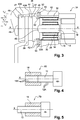
- the reduction gear 10 comprises an internal screw 12, rollers 14 arranged around the screw, a cage 16 for holding the rollers and a casing 18.
- the screw 12 has three threads 12A oriented in the same first direction.
- One end 20 of the screw 12 is intended to be rigidly fixed to a rotational drive means, such as an electric motor M of the actuator for example.
- the reducer is configured to be electrically controlled.
- the other end of the screw has a free, smooth and hollow edge.
- the rollers 14 are threaded and have a longitudinal axis parallel to the axis X of the screw. They each have a single thread 14A which comes into direct engagement with the threads 12A of the screw. The thread 14A of each roller 14 is oriented in an opposite direction to the threads 12A of the screw 12.
- the cage 16 for holding the rollers 14 has a cylindrical shape coaxial with the screw 12 and extending over a reduced portion of the length of the screw.
- This cage 16 has longitudinal housings 21 configured to receive the rollers at regular intervals around the screw.
- the housings 21 have bores 26 opening out at the ends of the cage.
- the rollers are provided with positioning pins 24 which are received in the bores 26 of the housings 21.
- each roller 14 is held by its ends in a housing 21 of the cage 16.
- the rollers are 10 in number and the roller holding cage 16 has ten housings, but could of course have a different number, depending on the number of rollers used.
- each roller 14 is mounted so that it can rotate in its housing 21.
- the casing 18 forms a cylindrical jacket surrounding the cage 16 and arranged coaxially with the screw 12.
- the casing 18 has an internal wall provided with a tapping provided with six threads 18A oriented in the same direction as that of the threads 14A of the rollers 14.
- the housing 18 comes into direct engagement with the rollers.
- One end 22 of the casing 18 is configured to be rigidly fixed to an element E intended to be moved in translation and thus guided to slide relative to the motor.
- rollers 14 are each in direct engagement on the one hand with the screw 12 and on the other hand with the casing 18 by means of at least one thread 14A oriented in the opposite direction to a thread 12A of the screw and in the same direction as a thread 18A of the housing 18.
- the reduction gear 10 is rotated by a shaft of an electric motor M of the “brushless” type capable of rotating in both directions of rotation.
- the electric motor M When the electric motor M is actuated in a first direction of rotation, the screw 12 drives the rollers 14 and the cage 16 in rotation about the axis X.
- the rollers 14 As the rollers 14 are engaged with the casing 18, their rotational movement generates a translational movement of the housing 18 along the axis X of the screw.
- the reducer makes it possible to move the element E in a translational movement from a rotational movement of the motor M.
- the element E is for example connected to a brake pad intended to come into contact with a disc of a disc brake.
- the joint translational movement of the casing and the element E is thus strongly reduced because it results from a difference in the number of threads 12A, 14A, 18A between, on the one hand, the screw and the rollers, on the other hand, the rollers and the housing, from a difference in diameter between the screw and the housing, but also the reverse direction of the threads of the screw and the rollers.
- reducer 23 which is adapted to be used as a brake actuator, comprises elements which are substantially identical to those previously presented, namely, a screw 12 having three threads 12A, rollers 14 provided with a thread 14A oriented in the opposite direction of the threads of the screw and a casing 18 provided with six internal threads 18A oriented in the same direction as the threads of the rollers.
- the rollers are called internal rollers 14 and the casing is called internal casing 18.
- the reducer also includes additional elements intended to increase the reduction capacity of such a reducer.
- these additional elements are external threaded rollers 28 and an external casing 30.
- the internal rollers 14 are therefore arranged around the screw 12 while the external rollers 28 are arranged peripherally to the internal casing 18 and are, like the internal rollers 14, each provided with a single thread 28A.
- the outer rollers 28 are housed in a cage (not shown) of shape substantially identical to that previously described, the diameter of which is adapted to accommodate the inner casing 18 and the outer rollers 28.
- the external casing 30 surrounds the cage 26 and has a cylindrical shape coaxial with the screw 12.
- the external casing 30 comprises a thread provided with six threads 30A on its internal wall.
- An element E intended to be moved in translation is rigidly fixed to one end 32 of the external casing 30 whose rotation is prohibited.
- the external rollers 28 each come into direct contact with the external casing 30 and with the internal casing 18.
- the thread 28A of each external roller 28 is oriented in the opposite direction to the threads 18A of the internal casing 18 and in the same direction as the threads of the external casing 30.
- the reduction gear is an electromechanical actuator 34 for vehicle braking which is an integral part of a braking device 35 of the disc brake type.
- a braking device 35 comprises said actuator 34, a brake disc 38, brake pads 40A, 40B and a floating caliper 36.
- the floating stirrup 36 has an attachment part 42, a disc passage 44 and a support jaw 48.
- the end of the floating bracket comprising the attachment part 42 is rigidly fixed to the external casing 30 of the reduction gear of the actuator 34.
- the other end of the floating bracket comprises the support jaw 48, which s' extends parallel to the disc 38 and carries one of the plates 40B.
- the disc passage 42 forms a housing for the disc 38 and the pads 40A, 40B.
- the brake pads 40A, 40B are arranged laterally, on either side of the disc 38 and each comprise a metal support 46 covered with a lining 47.
- a deformable circular seal 50 is disposed around the inner pad and connects an edge of the inner brake pad to an edge of the outer housing.
- the plates, the stirrup and the casing each have a housing 52 adapted to receive attachment parts of the seal. This seal is intended to isolate the actuator from any external pollution.
- the actuator 34 comprises a so-called double reduction gearbox of design substantially similar to that of the second embodiment described above.
- the constituent elements are therefore arranged as above, with the difference that in this embodiment the screw 12 is configured to translate parallel to the axis X, so that the screw forms a piston whose end connected to the wafer brake is adapted to come into contact with the brake disc 38.
- the internal casing 30 driven by the motor is fixed in translation.
- the internal casing 18 When the electric motor M is actuated in a first direction of rotation, the internal casing 18 starts to rotate.
- the internal rollers 14, which are in direct engagement with the internal casing 18, are driven in rotation about their own axis and, around the axis X of the screw 12. They are also moved in a translational movement T1 'parallel to the X axis.
- the rotation of the internal rollers 18 thus causes a translation T2 'of the screw 12 along the axis X, in a so-called positive direction, so that the end 54 of the screw displaces the internal brake pad 40A and pushes it. ci against the brake disc 38 to generate part of the vehicle braking.
- the rotation of the internal casing 18 causes the external rollers 28 to rotate about their own axis and around the axis X. Also, the external rollers move in a translational movement T3 'parallel to the axis X.
- the reduction gear is a braking actuator 60 provided with a casing 18, a screw 12 and a motor E, as shown in FIG. figure 4 .
- the actuator 60 does not have rollers while the screw 12 is in taken with the casing 18 in an irreversible connection.
- the screw 12 has three threads 12A and the casing has six threads 18A.
- the motor shaft M is directly fixed to the screw, while the casing forms the brake piston. It is therefore suitable for being able to be translated along the X axis so as to actuate a mobile element of a braking device.
- the actuator 70 comprises a casing 18 rigidly fixed to the shaft of the motor M while the screw 12 is movable in translation along the axis X.
- the screw forms the brake piston and translates along the X axis to activate a mobile element of a braking device.
- the electric motor is connected to the casing 18, and that it is the screw 12 which is moved in translation and changes the element E.
- the reduction gear comprises an external casing 30 which is fixed and that it is the screw 12 which is moved in translation by carrying the element E.
- the motor is not fixed to the internal casing, but that it directly drives one of the two cages for housing the rotating rollers.
Landscapes
- Engineering & Computer Science (AREA)
- General Engineering & Computer Science (AREA)
- Mechanical Engineering (AREA)
- Transportation (AREA)
- Braking Arrangements (AREA)
- Transmission Devices (AREA)
- Braking Systems And Boosters (AREA)
Description
- L'invention se rapporte au domaine des actionneurs de freinage pour véhicule, et plus spécifiquement au domaine des actionneurs de freinage de type électromécanique.
- On connait des véhicules qui utilisent des dispositifs de freinage hydraulique. De tels dispositifs mettent en œuvre des actionneurs hydrauliques comportant notamment un piston apte à pousser une plaquette de frein contre un disque relié rigidement à la roue du véhicule.
- Toutefois, depuis quelques années, on assiste à l'apparition de dispositifs de freinage électromécaniques qui sont actionnés électriquement plutôt que hydrauliquement. Ces dispositifs de freinage sont munis d'un actionneur électromécanique qui présente notamment l'avantage de réduire les coûts de fabrication du véhicule mais aussi son coût de maintenance en supprimant l'entretien d'un circuit hydraulique.
- Le document
DE 198 07 328 A1 décrit un dispositif de freinage électromécanique mettant en œuvre un actionneur électromécanique de freinage comprenant une vis, un carter interne taraudé en prise avec la vis au moyen d'une liaison irréversible, un moteur électrique de commande d'un mouvement de la vis par rapport au carter interne de sorte que ce mouvement actionne un élément de freinage, des rouleaux internes filetés, les rouleaux internes étant chacun en prise d'une part avec la vis et d'autre part avec le carter interne au moyen d'au moins un filet. - On connaît notamment de la demande
EP-1 359 338 , un dispositif de freinage électromécanique mettant en œuvre un actionneur électromécanique de freinage pourvu d'une vis à billes couplée à un moteur électrique. La vis à billes est adaptée pour transformer le mouvement de rotation du moteur électrique en un mouvement linéaire pour pousser la plaquette contre le disque de frein. La vis à billes comporte une vis, un carter et des billes destinées à réduire les frottements entre la vis et le carter. - L'inconvénient majeur de l'actionneur de l'art antérieur est lié à la présence de la vis à billes dont une des caractéristiques est la réversibilité. On entend par réversibilité le fait qu'un effort axial appliqué sur la vis génère une rotation du carter, et réciproquement, qu'un effort axial appliqué sur le carter génère une rotation de la vis. On comprend que la réversibilité constitue un inconvénient sérieux dans la mesure où un déplacement imprévu de la vis ou du carter selon un mouvement de translation pourrait affecter la fiabilité du freinage et ainsi compromettre la sécurité des passagers du véhicule.
- Par ailleurs, pour des questions de coût, l'utilisation d'un actionneur de freinage électromécanique mettant en œuvre une vis à billes n'est pas satisfaisante.
- A cet effet, l'invention a pour objet un actionneur de freinage de véhicule comportant :
- une vis,
- un carter interne taraudé en prise avec la vis au moyen d'une liaison irréversible,
- un moteur électrique de commande d'un mouvement de la vis par rapport au carter interne ou du carter interne par rapport à la vis de sorte que ce mouvement actionne un élément de freinage,
- des rouleaux internes filetés, les rouleaux internes étant chacun en prise d'une part avec la vis et d'autre part avec le carter interne au moyen d'au moins un filet,
- un carter externe taraudé, et
- des rouleaux externes en prise chacun d'une part avec le carter interne et d'autre part avec le carter externe, les rouleaux externes étant munis d'au moins un filet orienté en sens inverse d'un filet du carter interne et dans le même sens qu'un filet du carter externe.
- Ainsi, un actionneur selon l'invention permet de supprimer les inconvénients précités.
- On comprend notamment qu'un tel actionneur de freinage présente l'avantage que la vis et le carter interne ne peuvent être déplacés l'un par rapport à l'autre que par le mouvement de rotation du moteur électrique. Ainsi, cet actionneur évite tout déplacement inopiné de la vis par rapport au carter interne. Ceci est particulièrement intéressant lorsque l'actionneur est utilisé dans une configuration de type frein de parking car cela permet d'améliorer la fiabilité du freinage d'un véhicule. Par ailleurs, un tel actionneur de freinage présente un coût particulièrement faible en mettant en œuvre des éléments peu onéreux et bien plus faciles à fabriquer que les éléments d'un actionneur munis d'une vis à billes notamment.
- De plus, pour ce type d'actionneur, dit à « double étage de réduction », l'orientation dans le même sens des filets des rouleaux externes en prise avec ceux du carter externe offre une capacité de réduction qui est améliorée.
- En outre, comme l'actionneur comporte des rouleaux internes filetés, les rouleaux étant chacun en prise d'une part avec la vis et d'autre part avec le carter interne au moyen d'au moins un filet, l'actionneur sert de réducteur et l'utilisation d'un moteur électrique tournant à des vitesses de rotation élevées est rendue possible. Cela permet notamment d'utiliser un moteur dont le coût est faible.
- De préférence, la vis et le carter interne comportent chacun plusieurs filets, de préférence trois filets.
- Ainsi, la capacité de réduction de l'actionneur est encore augmentée.
- Par exemple, le filet de chaque rouleau est orienté en sens inverse d'un filet de la vis et dans le même sens qu'un filet du carter interne.
- Ainsi, la capacité de réduction peut être augmentée jusqu'à un rapport de 1/180.
- De préférence encore, les rouleaux sont en prise directe avec la vis et le carter interne.
- On peut prévoir que le carter interne forme un piston agencé pour actionner l'élément de freinage.
- Ainsi, il n'y a pas besoin d'utiliser une pièce supplémentaire destinée à se déplacer en translation pour actionner l'élément de freinage.
- Avantageusement, la vis forme un piston agencé pour actionner l'élément de freinage.
- Là aussi, il n'y a pas besoin de prévoir une pièce additionnelle qui serait vouée à actionner l'élément mobile de freinage.
- L'invention a également pour objet un dispositif de freinage de véhicule comportant l'actionneur tel que précité qui est configuré pour actionner un frein à disque, de préférence à étrier flottant.
- L'invention a encore pour objet un véhicule muni d'un dispositif de freinage dans lequel l'actionneur est configuré pour actionner un frein de service ou un frein de parking.
- Ainsi, un tel actionneur peut être envisagé dans différentes configurations de dispositifs de freinage.
- Egalement, on prévoit que le dispositif comporte un actionneur dans lequel la vis et les carters sont fabriqués en un matériau polymère chargé d'un renfort.
- Nous allons maintenant décrire cinq modes de réalisation de l'invention à titre d'exemples non limitatifs, en référence aux dessins annexés, sur lesquels :
- la
figure 1 est une vue en perspective d'un actionneur formant un premier mode de réalisation de l'invention, dans lequel le carter est représenté en coupe ; - la
figure 2 est une vue en coupe d'un actionneur formant un second mode de réalisation de l'invention ; - la
figure 3 est une vue en coupe d'un actionneur de freinage formant un troisième mode de réalisation de l'invention ; - la
figure 4 est une vue en perspective d'un actionneur de freinage formant un quatrième mode de réalisation de l'invention et ; - la
figure 5 est une vue en perspective d'un actionneur de freinage formant un cinquième mode de réalisation de l'invention. - En référence à la
figure 1 , dans l'actionneur de freinage selon l'invention, le réducteur 10 comporte une vis interne 12, des rouleaux 14 agencés autour de la vis, une cage 16 de maintien des rouleaux et un carter 18. - La vis 12 présente trois filets 12A orientés selon un même premier sens. Une extrémité 20 de la vis 12 est destinée à être rigidement fixée à un moyen d'entrainement en rotation, tel qu'un moteur électrique M de l'actionneur par exemple. Ainsi, le réducteur est configuré pour être commandé électriquement. L'autre extrémité de la vis comporte un bord libre, lisse et creux.
- Les rouleaux 14 sont filetés et ont un axe longitudinal parallèle à l'axe X de la vis. Ils présentent chacun un unique filet 14A qui vient en prise directe avec les filets 12A de la vis. Le filet 14A de chaque rouleau 14 est orienté selon un sens inverse des filets 12A de la vis 12.
- La cage 16 de maintien des rouleaux 14 présente une forme cylindrique coaxiale à la vis 12 et s'étendant sur une portion réduite de la longueur de la vis. Cette cage 16 comporte des logements longitudinaux 21 configurés pour accueillir les rouleaux à intervalles réguliers autour de la vis. A cet effet, les logements 21 comportent des alésages 26 débouchant aux extrémités de la cage. A leurs extrémités, les rouleaux sont munis de pions de positionnement 24 qui viennent se loger dans les alésages 26 des logements 21. Ainsi, chaque rouleau 14 est maintenu par ses extrémités dans un logement 21 de la cage 16. Dans cet exemple, les rouleaux sont au nombre de 10 et la cage 16 de maintien des rouleaux comporte dix logements, mais pourrait bien sûr en comporter un nombre différent, en fonction du nombre de rouleaux mis en œuvre. Ainsi, chaque rouleau 14 est monté mobile à rotation dans son logement 21.
- Le carter 18 forme une chemise cylindrique entourant la cage 16 et agencée coaxialement avec la vis 12. Le carter 18 comporte une paroi interne pourvue d'un taraudage muni de six filets 18A orientés dans le même sens que celui des filets 14A des rouleaux 14. Le carter 18 vient en prise directe avec les rouleaux. Une extrémité 22 du carter 18 est configurée pour être fixée rigidement à un élément E destiné à être déplacé en translation et ainsi guidé à coulissement par rapport au moteur.
- Ainsi, les rouleaux 14 sont chacun en prise directe d'une part avec la vis 12 et d'autre part avec le carter 18 au moyen d'au moins un filet 14A orienté en sens inverse d'un filet 12A de la vis et dans le même sens qu'un filet 18A du carter 18.
- Nous allons maintenant présenter le fonctionnement du réducteur 10. On suppose que le réducteur 10 est entraîné en rotation par un arbre d'un moteur électrique M de type « brushless » apte à tourner dans les deux sens de rotation. Lorsque le moteur électrique M est actionné selon un premier sens de rotation, la vis 12 entraîne les rouleaux 14 et la cage 16 en rotation autour de l'axe X. Comme les rouleaux 14 sont en prise avec le carter 18, leur mouvement de rotation génère un mouvement de translation du carter 18 selon l'axe X de la vis.
- En d'autres termes, il existe un déplacement axial selon l'axe X entre la vis 12 et les rouleaux 14, entre les rouleaux 14 et le carter 18, et entre le carter 14 et la vis 12. Ainsi, le réducteur permet de déplacer l'élément E selon un mouvement de translation à partir d'un mouvement de rotation du moteur M. L'élément E est par exemple relié à une plaquette de frein destinée à venir en contact avec un disque d'un frein à disque.
- Le mouvement de translation conjoint du carter et de l'élément E est ainsi fortement réduit car il résulte d'une différence du nombre de filets 12A, 14A, 18A entre, d'une part, la vis et les rouleaux, d'autre part, les rouleaux et le carter, d'une différence de diamètre entre la vis et le carter, mais également du sens inversé des filets de la vis et des rouleaux.
- Dans le cas d'une rotation du moteur M dans le sens inverse, on comprend que les mouvements de rotation et de translation décrits ci-dessus sont inversés, générant ainsi un mouvement de translation de l'élément E dans le sens inverse.
- On va maintenant décrire ci-dessous d'autres modes de réalisation de l'invention, en se référant aux
figures 2 à 5 sur lesquelles les éléments analogues à ceux de lafigure 1 sont désignés par des références identiques. - En référence à la
figure 2 , on a représenté un second mode de réalisation d'un réducteur 23, dit réducteur « à double étage de réduction ». Ce type de réducteur 23, qui est adapté pour être utilisé comme actionneur de freinage, comporte des éléments sensiblement identiques à ceux précédemment présentés, à savoir, une vis 12 présentant trois filets 12A, des rouleaux 14 munis d'un filet 14A orienté dans le sens inverse des filets de la vis et un carter 18 muni de six filets internes 18A orientés dans le même sens que les filets des rouleaux. Dans ce mode de réalisation, les rouleaux sont appelés rouleaux internes 14 et le carter est dit carter interne 18. Ces éléments sont agencés les uns par rapport aux autres comme dans le mode de réalisation précédent, à la différence qu'ici l'arbre du moteur M est fixé au carter interne 18 au lieu d'être fixé à la vis 12. Egalement de manière différente au mode de réalisation précédemment décrit, la vis 12 est rigidement fixée à un bâti accueillant le réducteur et le moteur M est monté coulissant selon l'axe X par rapport au bâti. - Le réducteur comporte également des éléments supplémentaires destinés à augmenter la capacité de réduction d'un tel réducteur. En l'occurrence, ces éléments supplémentaires sont des rouleaux externes filetés 28 et un carter externe 30.
- Les rouleaux internes 14 sont donc agencés autour de la vis 12 tandis que les rouleaux externes 28 sont agencés périphériquement au carter interne 18 et sont, tout comme les rouleaux internes 14, chacun munis d'un seul filet 28A. Les rouleaux externes 28 sont logés dans une cage (non représentée) de forme sensiblement identique à celle précédemment décrite dont le diamètre est adapté pour accueillir le carter interne 18 et les rouleaux externes 28.
- Le carter externe 30 entoure la cage 26 et a une forme cylindrique coaxiale avec la vis 12. Le carter externe 30 comporte un taraudage pourvu de six filets 30A sur sa paroi interne. Un élément E destiné à être déplacé en translation est rigidement fixé à une extrémité 32 du carter externe 30 dont toute rotation est interdite.
- Les rouleaux externes 28 viennent chacun en prise directe avec le carter externe 30 et avec le carter interne 18. Le filet 28A de chaque rouleau externe 28 est orienté en sens inverse des filets 18A du carter interne 18 et dans le même sens que les filets du carter externe 30.
- Nous allons maintenant présenter le fonctionnement du réducteur 23 selon ce second mode de réalisation. Lorsque le moteur électrique M est actionné selon un premier sens de rotation, les rouleaux internes 14, qui sont en prise directe avec le carter interne 18, sont entraînés en rotation autour de l'axe X de la vis et également en rotation sur eux-mêmes selon leurs axes propres. Ces mouvements de rotation génèrent un déplacement en translation de la cage et des rouleaux selon un mouvement de translation T1 parallèle à l'axe X. Comme les rouleaux internes 14 se déplacent en translation sur la vis 12 qui est fixe, le carter interne 18 et l'arbre du moteur M sont entraînés par les rouleaux internes 14 selon un mouvement de translation T2 parallèle à l'axe X.
- Concernant les rouleaux externes 28, ceux-ci sont entraînés en rotation par le carter interne 18, et évoluent selon un mouvement de translation T3 parallèle à l'axe X.
- Enfin, la rotation des rouleaux externes 28 entraîne le carter externe selon un mouvement de translation T4 parallèle à l'axe X.
- En référence à la
figure 3 , on va maintenant décrire un troisième mode de réalisation dans lequel, comme dans les précédents modes, le réducteur est un actionneur électromécanique de freinage 34 de véhicule faisant partie intégrante d'un dispositif de freinage 35 de type frein à disque. Un tel dispositif de freinage 35 comprend ledit actionneur 34, un disque de frein 38, des plaquettes de frein 40A, 40B et un étrier flottant 36. - L'étrier flottant 36 comporte une partie d'attache 42, un passage de disque 44 et un mors d'appui 48.
- L'extrémité de l'étrier flottant comportant la partie d'attache 42 est rigidement fixée au carter externe 30 du réducteur de l'actionneur 34. L'autre extrémité de l'étrier flottant comporte le mors d'appui 48, lequel s'étend parallèlement au disque 38 et porte une des plaquettes 40B. Entre les deux extrémités de l'étrier flottant 36, le passage de disque 42 forme un logement pour le disque 38 et les plaquettes 40A, 40B.
- De manière classique, les plaquettes de freins 40A, 40B sont disposées latéralement, de part et d'autre du disque 38 et comportent chacune un support métallique 46 recouvert d'une garniture 47. On distingue la plaquette de frein intérieure 40A dont le support 46 est rigidement fixé à une extrémité 49 de la vis 12, et la plaquette extérieure 40B dont le support 46 est rigidement fixé au mors d'appui de l'étrier. Un joint d'étanchéité circulaire déformable 50 est disposé autour de la plaquette intérieure et relie un bord de la plaquette de frein intérieure à un bord du carter externe. A cet effet, les plaquettes, l'étrier et le carter comportent chacun un logement 52 adapté pour accueillir des parties d'attache du joint. Ce joint est destiné à isoler l'actionneur de toute pollution extérieure.
- L'actionneur 34 comporte un réducteur dit à double étage de réduction de conception sensiblement semblable à celui du second mode de réalisation précédemment décrit. Les éléments constitutifs sont donc agencés comme précédemment, à la différence près que dans ce mode de réalisation la vis 12 est configurée pour translater parallèlement à l'axe X, de telle sorte que la vis forme un piston dont l'extrémité reliée à la plaquette de frein est adaptée pour venir au contact du disque de frein 38. Dans cet exemple, le carter interne 30 entraîné par le moteur est fixe en translation.
- On va maintenant décrire le fonctionnement de l'actionneur de freinage 34 utilisé dans le dispositif de freinage 35 ci-dessus.
- Lorsque le moteur électrique M est actionné selon un premier sens de rotation, le carter interne 18 entre en rotation. Les rouleaux internes 14, qui sont en prise directe avec le carter interne 18, sont entraînés en rotation autour de leur axe propre et, autour de l'axe X de la vis 12. Ils sont également déplacés selon un mouvement de translation T1' parallèle à l'axe X.
- La rotation des rouleaux internes 18 entraine ainsi une translation T2' de la vis 12 selon l'axe X, dans un sens dit positif, de telle sorte que l'extrémité 54 de la vis déplace la plaquette de frein intérieure 40A et pousse celle-ci contre le disque de frein 38 pour générer une partie du freinage du véhicule.
- Par ailleurs, la rotation du carter interne 18 entraine les rouleaux externes 28 en rotation autour de leur axe propre et autour de l'axe X. Aussi, les rouleaux externes évoluent selon un mouvement de translation T3' parallèle à l'axe X.
- Enfin, la rotation des rouleaux externes 28 entraîne le carter externe 30 selon un mouvement de translation T4' parallèle à l'axe X, dans un sens dit négatif, générant ainsi un déplacement en translation de l'étrier dans le sens négatif. La plaquette externe 40B vient donc en contact avec le disque de frein 38, générant ainsi une autre partie du freinage du véhicule. Le disque 38 est donc pressé entre les deux plaquettes 40A, 40B.
- On comprend que lorsque l'arbre du moteur électrique M tourne dans l'autre sens, les mouvements de rotation et de translation décrits ci-avant sont inversés et que les plaquettes de frein translatent parallèlement à l'axe X en s'éloignant du disque de frein.
- Dans un quatrième mode de réalisation de l'invention, le réducteur est un actionneur de freinage 60 muni d'un carter 18, d'une vis 12 et d'un moteur E, comme montré à la
figure 4 . Ici, l'actionneur 60 ne comporte pas de rouleaux tandis que la vis 12 est en prise avec le carter 18 selon une liaison irréversible. Comme précédemment, la vis 12 comporte trois filets 12A et le carter compte six filets 18A. L'arbre du moteur M est directement fixé à la vis, tandis que le carter forme piston de frein. Il est donc adapté pour pourvoir être translaté selon l'axe X de manière à actionner un élément mobile d'un dispositif de freinage. - Selon un cinquième mode de réalisation représenté à la
figure 5 , l'actionneur 70 comporte un carter 18 rigidement fixé à l'arbre du moteur M tandis que la vis 12 est mobile en translation suivant l'axe X. Ainsi, lorsque le moteur M est activé, la vis forme piston de frein et translate selon l'axe X pour actionner un élément mobile d'un dispositif de freinage. - L'invention n'est pas limitée aux modes de réalisation présentés et d'autres modes de réalisation apparaîtront clairement à l'homme du métier. Il est notamment possible de prévoir, en variante du premier mode de réalisation, que le moteur électrique est relié au carter 18, et que c'est la vis 12 qui est déplacée en translation et fait évoluer l'élément E.
- En variante du second mode de réalisation, on peut aussi prévoir que le réducteur comporte un carter externe 30 qui est fixe et que c'est la vis 12 qui est mue en translation en portant l'élément E.
- Également, en variante du deuxième ou du troisième mode de réalisation, on peut prévoir que le moteur n'est pas fixé au carter interne, mais qu'il entraîne directement une des deux cages de logement des rouleaux en rotation.
-
- 10 : réducteur
- 12 : vis
- 12A : filets de la vis
- 14 : rouleaux ; rouleaux internes
- 14 A : filet d'un rouleau ; filet d'un rouleau interne
- 16 : cage
- 18 : carter ; carter interne
- 18 A : filets du taraudage du carter ; filets du taraudage du carter interne
- 18 B : filets sur paroi externe du carter interne
- 20 : extrémité de la vis
- 21 : logements
- 22 : extrémité du carter
- 23 : réducteur dit « à double étage de réduction »
- 24 : pions de positionnement
- 26 : alésages
- 28 : rouleaux externes
- 28 A : filet d'un rouleau externe
- 30 : carter externe
- 30 A : filets du taraudage du carter externe
- 32 : extrémité du carter externe
- 34 : actionneur de freinage
- 35 : dispositif de freinage
- 36 : étrier flottant
- 38 : disque de frein
- 40 : plaquettes de frein
- 42 : parti d'attache
- 44 : passage de disque
- 46 : support
- 47 : garniture
- 50 : joint d'étanchéité
- 52 : logement
- 54 : extrémité de la vis
- 60 : actionneur de freinage
- 70 : actionneur de freinage
- T1 : mouvement de translation des rouleaux internes
- T2 : mouvement de translation du carter interne
- T3 : mouvement de translation des rouleaux externes
- T4 : mouvement de translation du carter externe
- T1' : mouvement de translation des rouleaux internes
- T2' : mouvement de translation de la vis
- T3' : mouvement de translation des rouleaux externes
- T4' : mouvement de translation du carter externe
- E : élément destiné à être déplacé en translation
- M : moteur électrique
- X : axe de la vis
Claims (8)
- Actionneur de freinage (10 ; 23 ; 34 ; 60 ; 70) de véhicule, comportant :- une vis (12),- un carter interne taraudé (18) en prise avec la vis (12) au moyen d'une liaison irréversible,- un moteur électrique (M) de commande d'un mouvement de la vis (12) par rapport au carter interne (18) ou du carter interne par rapport à la vis de sorte que ce mouvement actionne un élément de freinage (E),- des rouleaux internes filetés (14), les rouleaux internes (14) étant chacun en prise d'une part avec la vis (12) et d'autre part avec le carter interne (18) ; etcaractérisé en ce que les rouleaux internes (14) sont chacun en prise d'une part avec la vis (12) et d'autre part avec le carter interne (18) au moyen d'au moins un filet (14A), et en ce qu'il comporte :- un carter externe taraudé (30), et- des rouleaux externes (28) en prise chacun d'une part avec le carter interne (18) et d'autre part avec le carter externe (30), les rouleaux externes (28) étant munis d'au moins un filet (28A) orienté en sens inverse d'un filet (18A) du carter interne (18) et dans le même sens qu'un filet (30A) du carter externe (30).
- Actionneur selon la revendication précédente dans lequel la vis (12) et le carter interne (18) comportent chacun plusieurs filets, de préférence au moins trois filets (12A, 18A).
- Actionneur selon l'une quelconque des revendications précédentes dans lequel le filet (14A) de chaque rouleau interne (14) est orienté en sens inverse d'un filet (12A) de la vis (12) et dans le même sens qu'un filet (18A) du carter interne.
- Actionneur selon au moins l'une quelconque des revendications précédentes dans lequel les rouleaux internes (14) sont en prise directe avec la vis (12) et le carter interne (18).
- Actionneur selon au moins l'une quelconque des revendications précédentes, dans lequel le carter interne (18) forme un piston agencé pour actionner l'élément (E) de freinage.
- Actionneur selon au moins l'une quelconque des revendications précédentes, dans lequel la vis (12) forme un piston agencé pour actionner l'élément (E) de freinage.
- Dispositif de freinage de véhicule, comportant un actionneur selon au moins l'une quelconque des revendications précédentes configuré pour actionner un frein à disque, de préférence à étrier flottant.
- Véhicule muni d'un dispositif de freinage selon la revendication précédente, dans lequel l'actionneur est configuré pour actionner un frein de service ou un frein de parking.
Priority Applications (1)
| Application Number | Priority Date | Filing Date | Title |
|---|---|---|---|
| PL15753724T PL3175136T3 (pl) | 2014-07-30 | 2015-07-20 | Siłownik hamulcowy do pojazdu |
Applications Claiming Priority (2)
| Application Number | Priority Date | Filing Date | Title |
|---|---|---|---|
| FR1457398A FR3024513B1 (fr) | 2014-07-30 | 2014-07-30 | Actionneur de freinage pour vehicule |
| PCT/FR2015/051989 WO2016016541A1 (fr) | 2014-07-30 | 2015-07-20 | Actionneur de freinage pour véhicule |
Publications (2)
| Publication Number | Publication Date |
|---|---|
| EP3175136A1 EP3175136A1 (fr) | 2017-06-07 |
| EP3175136B1 true EP3175136B1 (fr) | 2020-02-12 |
Family
ID=52016714
Family Applications (1)
| Application Number | Title | Priority Date | Filing Date |
|---|---|---|---|
| EP15753724.2A Active EP3175136B1 (fr) | 2014-07-30 | 2015-07-20 | Actionneur de freinage pour véhicule |
Country Status (8)
| Country | Link |
|---|---|
| US (1) | US10890225B2 (fr) |
| EP (1) | EP3175136B1 (fr) |
| JP (1) | JP6612321B2 (fr) |
| CN (1) | CN106662183A (fr) |
| ES (1) | ES2788871T3 (fr) |
| FR (1) | FR3024513B1 (fr) |
| PL (1) | PL3175136T3 (fr) |
| WO (1) | WO2016016541A1 (fr) |
Families Citing this family (5)
| Publication number | Priority date | Publication date | Assignee | Title |
|---|---|---|---|---|
| US20170045105A1 (en) * | 2015-08-04 | 2017-02-16 | Persimmon Technologies, Corp. | Electric Brake Caliper |
| EP3332154A1 (fr) * | 2015-08-07 | 2018-06-13 | Aktiebolaget SKF | Mécanisme de vis à rouleaux comprenant une cage |
| KR102522518B1 (ko) * | 2018-04-26 | 2023-04-17 | 에이치엘만도 주식회사 | 회전 나사를 이용한 피스톤 전후진 왕복 운동 장치 |
| CN113531071B (zh) * | 2021-07-29 | 2025-06-06 | 陕西国力信息技术有限公司 | 输出轴非旋转的平动力传递机构及电动制动装置 |
| CN114483902B (zh) * | 2022-02-22 | 2025-02-14 | 西安华欧精密机械有限责任公司 | 一种双层螺纹滚道的滚珠丝杠副 |
Family Cites Families (17)
| Publication number | Priority date | Publication date | Assignee | Title |
|---|---|---|---|---|
| US4877113A (en) * | 1988-04-19 | 1989-10-31 | Allied-Signal Inc. | One-way clutch preventing back drive of reversible motor |
| JPH08296674A (ja) * | 1995-04-26 | 1996-11-12 | Akebono Brake Res & Dev Center Ltd | ブレーキ装置 |
| DE19543098C2 (de) * | 1995-05-19 | 1997-03-20 | Continental Ag | Bremsaktor für elektrisch betätigbare Fahrzeugbremse |
| EP0743470B1 (fr) | 1995-05-19 | 2000-08-09 | Continental Aktiengesellschaft | Moteur de frein pour frein à actionnement électrique de véhicule |
| NL1006544C2 (nl) * | 1997-07-10 | 1999-01-12 | Skf Ind Trading & Dev | Actuator voorzien van een beschermd schroefmechanisme, alsmede remklauw met een dergelijke actuator. |
| NL1007296C2 (nl) * | 1997-10-16 | 1999-04-19 | Skf Ind Trading & Dev | Modulaire actuator, alsmede remklauw met een dergelijke actuator. |
| DE19807328C2 (de) | 1998-02-20 | 2003-08-28 | Lucas Ind Plc | Elektromechanisch betätigbare Scheibenbremse |
| NL1009197C2 (nl) * | 1998-05-18 | 1999-11-19 | Skf Eng & Res Centre Bv | Schroefactuator, en remklauw met een dergelijke schroefactuator. |
| FR2839127B1 (fr) * | 2002-04-24 | 2004-06-25 | Transrol | Dispositif d'actionnement a elements roulants intermediaires |
| US20030205437A1 (en) | 2002-05-02 | 2003-11-06 | Drennen David B. | Gear-driven electric mechanical brake assembly and motor subassembly therefor |
| JP2005133863A (ja) * | 2003-10-31 | 2005-05-26 | Toyota Motor Corp | 制動装置 |
| US7267044B1 (en) * | 2005-03-01 | 2007-09-11 | John Hamilton Klinger | Compact actuator with large thrust |
| EP1929170B1 (fr) * | 2005-09-27 | 2009-03-04 | Lucas Automotive Gmbh | Frein de vehicule, en particulier frein a etrier |
| US8864103B2 (en) * | 2007-10-02 | 2014-10-21 | Aktiebolaget Skf | Valve actuator |
| FR2951514B1 (fr) * | 2009-10-16 | 2012-03-30 | Thales Sa | Vis a rouleaux differentiellle |
| WO2015007308A1 (fr) * | 2013-07-16 | 2015-01-22 | Aktiebolaget Skf | Ensemble mécanisme de commande de vanne à vis à rouleaux inversée |
| FR3024516B1 (fr) * | 2014-07-30 | 2018-01-19 | Chassis Brakes International B.V. | Reducteur de couple |
-
2014
- 2014-07-30 FR FR1457398A patent/FR3024513B1/fr not_active Expired - Fee Related
-
2015
- 2015-07-20 US US15/321,237 patent/US10890225B2/en not_active Expired - Fee Related
- 2015-07-20 WO PCT/FR2015/051989 patent/WO2016016541A1/fr not_active Ceased
- 2015-07-20 ES ES15753724T patent/ES2788871T3/es active Active
- 2015-07-20 JP JP2017503125A patent/JP6612321B2/ja active Active
- 2015-07-20 PL PL15753724T patent/PL3175136T3/pl unknown
- 2015-07-20 EP EP15753724.2A patent/EP3175136B1/fr active Active
- 2015-07-20 CN CN201580039523.XA patent/CN106662183A/zh active Pending
Non-Patent Citations (1)
| Title |
|---|
| None * |
Also Published As
| Publication number | Publication date |
|---|---|
| US20170204924A1 (en) | 2017-07-20 |
| FR3024513A1 (fr) | 2016-02-05 |
| WO2016016541A1 (fr) | 2016-02-04 |
| ES2788871T3 (es) | 2020-10-23 |
| CN106662183A (zh) | 2017-05-10 |
| PL3175136T3 (pl) | 2020-06-29 |
| FR3024513B1 (fr) | 2018-01-19 |
| JP6612321B2 (ja) | 2019-11-27 |
| EP3175136A1 (fr) | 2017-06-07 |
| JP2017522512A (ja) | 2017-08-10 |
| US10890225B2 (en) | 2021-01-12 |
Similar Documents
| Publication | Publication Date | Title |
|---|---|---|
| EP3676144B1 (fr) | Etrier de frein a disque de type electromecanique comprenant deux actionneurs mecaniques pour compenser une usure inégale d'une même plaquette | |
| EP3089901B1 (fr) | Motoreducteur a train epicycloidal, frein a tambour, frein a disque et dispositif de freinage ainsi equipes | |
| EP3089899B1 (fr) | Actionneur entraine par pignon a glissiere axiale, et frein a tambour et dispositif de freinage ainsi equipes | |
| EP3175146B1 (fr) | Réducteur de couple | |
| EP3090190B1 (fr) | Actionneur avec systeme vis-ecrou irreversible, frein a tambour et dispositif de freinage ainsi equipes | |
| EP3175136B1 (fr) | Actionneur de freinage pour véhicule | |
| EP3089896B1 (fr) | Actionneur avec sous-ensemble de transmission a engrenage, et frein a tambour et dispositif de freinage ainsi equipes | |
| EP3397872B1 (fr) | Etrier fixe de frein a disque avec actionneur electrique integre | |
| EP1352181A1 (fr) | Actionneur electromecanique de frein a disques multiples pour moyen de transport, notamment pour avion | |
| FR3017173A1 (fr) | Dispositif de transmission pour commander le mouvement de translation d'un organe et systeme de freinage equipe d'un tel dispositif de transmission formant un servofrein | |
| FR3016013A1 (fr) | Actionneur de frein a tambour avec motorisation par emboitement a jeu angulaire | |
| EP3089900B1 (fr) | Motoreducteur avec moteur electrique adaptable pour actionneur de frein a tambour | |
| EP2576302B1 (fr) | Système de freins à servofrein à vis à billes coaxiales | |
| FR2898652A1 (fr) | Frein de stationnement de vehicule | |
| EP1610026B1 (fr) | Etrier de frein à disque électromécanique | |
| EP3902727B1 (fr) | Motoreducteur pour frein à tambour | |
| FR3038678A1 (fr) | Actionneur de frein a double demultiplication, etrier et frein, et procede d'actionnement | |
| FR3097021A1 (fr) | Reducteur et motoreducteur pour frein a débrayage intégré | |
| FR3079191A1 (fr) | Dispositif d'appplication de deux forces de sens opposes et systeme de frein de parking comportant un tel dispositif | |
| WO2025078665A1 (fr) | Frein à disque, notamment pour véhicule automobile | |
| EP4559767A1 (fr) | Frein a disque, notamment pour vehicule automobile | |
| FR2899546A1 (fr) | Actionneur de frein de stationnement electrique |
Legal Events
| Date | Code | Title | Description |
|---|---|---|---|
| STAA | Information on the status of an ep patent application or granted ep patent |
Free format text: STATUS: THE INTERNATIONAL PUBLICATION HAS BEEN MADE |
|
| 17P | Request for examination filed |
Effective date: 20170124 |
|
| AK | Designated contracting states |
Kind code of ref document: A1 Designated state(s): AL AT BE BG CH CY CZ DE DK EE ES FI FR GB GR HR HU IE IS IT LI LT LU LV MC MK MT NL NO PL PT RO RS SE SI SK SM TR |
|
| AX | Request for extension of the european patent |
Extension state: BA ME |
|
| PUAI | Public reference made under article 153(3) epc to a published international application that has entered the european phase |
Free format text: ORIGINAL CODE: 0009012 |
|
| STAA | Information on the status of an ep patent application or granted ep patent |
Free format text: STATUS: REQUEST FOR EXAMINATION WAS MADE |
|
| DAV | Request for validation of the european patent (deleted) | ||
| DAX | Request for extension of the european patent (deleted) | ||
| GRAP | Despatch of communication of intention to grant a patent |
Free format text: ORIGINAL CODE: EPIDOSNIGR1 |
|
| STAA | Information on the status of an ep patent application or granted ep patent |
Free format text: STATUS: GRANT OF PATENT IS INTENDED |
|
| INTG | Intention to grant announced |
Effective date: 20190905 |
|
| GRAS | Grant fee paid |
Free format text: ORIGINAL CODE: EPIDOSNIGR3 |
|
| GRAA | (expected) grant |
Free format text: ORIGINAL CODE: 0009210 |
|
| STAA | Information on the status of an ep patent application or granted ep patent |
Free format text: STATUS: THE PATENT HAS BEEN GRANTED |
|
| AK | Designated contracting states |
Kind code of ref document: B1 Designated state(s): AL AT BE BG CH CY CZ DE DK EE ES FI FR GB GR HR HU IE IS IT LI LT LU LV MC MK MT NL NO PL PT RO RS SE SI SK SM TR |
|
| REG | Reference to a national code |
Ref country code: GB Ref legal event code: FG4D Free format text: NOT ENGLISH |
|
| REG | Reference to a national code |
Ref country code: CH Ref legal event code: EP |
|
| REG | Reference to a national code |
Ref country code: AT Ref legal event code: REF Ref document number: 1232508 Country of ref document: AT Kind code of ref document: T Effective date: 20200215 |
|
| REG | Reference to a national code |
Ref country code: IE Ref legal event code: FG4D Free format text: LANGUAGE OF EP DOCUMENT: FRENCH |
|
| REG | Reference to a national code |
Ref country code: DE Ref legal event code: R096 Ref document number: 602015046822 Country of ref document: DE |
|
| PG25 | Lapsed in a contracting state [announced via postgrant information from national office to epo] |
Ref country code: NO Free format text: LAPSE BECAUSE OF FAILURE TO SUBMIT A TRANSLATION OF THE DESCRIPTION OR TO PAY THE FEE WITHIN THE PRESCRIBED TIME-LIMIT Effective date: 20200512 Ref country code: FI Free format text: LAPSE BECAUSE OF FAILURE TO SUBMIT A TRANSLATION OF THE DESCRIPTION OR TO PAY THE FEE WITHIN THE PRESCRIBED TIME-LIMIT Effective date: 20200212 Ref country code: RS Free format text: LAPSE BECAUSE OF FAILURE TO SUBMIT A TRANSLATION OF THE DESCRIPTION OR TO PAY THE FEE WITHIN THE PRESCRIBED TIME-LIMIT Effective date: 20200212 |
|
| REG | Reference to a national code |
Ref country code: LT Ref legal event code: MG4D |
|
| REG | Reference to a national code |
Ref country code: NL Ref legal event code: MP Effective date: 20200212 |
|
| PG25 | Lapsed in a contracting state [announced via postgrant information from national office to epo] |
Ref country code: GR Free format text: LAPSE BECAUSE OF FAILURE TO SUBMIT A TRANSLATION OF THE DESCRIPTION OR TO PAY THE FEE WITHIN THE PRESCRIBED TIME-LIMIT Effective date: 20200513 Ref country code: IS Free format text: LAPSE BECAUSE OF FAILURE TO SUBMIT A TRANSLATION OF THE DESCRIPTION OR TO PAY THE FEE WITHIN THE PRESCRIBED TIME-LIMIT Effective date: 20200612 Ref country code: HR Free format text: LAPSE BECAUSE OF FAILURE TO SUBMIT A TRANSLATION OF THE DESCRIPTION OR TO PAY THE FEE WITHIN THE PRESCRIBED TIME-LIMIT Effective date: 20200212 Ref country code: LV Free format text: LAPSE BECAUSE OF FAILURE TO SUBMIT A TRANSLATION OF THE DESCRIPTION OR TO PAY THE FEE WITHIN THE PRESCRIBED TIME-LIMIT Effective date: 20200212 Ref country code: SE Free format text: LAPSE BECAUSE OF FAILURE TO SUBMIT A TRANSLATION OF THE DESCRIPTION OR TO PAY THE FEE WITHIN THE PRESCRIBED TIME-LIMIT Effective date: 20200212 Ref country code: BG Free format text: LAPSE BECAUSE OF FAILURE TO SUBMIT A TRANSLATION OF THE DESCRIPTION OR TO PAY THE FEE WITHIN THE PRESCRIBED TIME-LIMIT Effective date: 20200512 |
|
| PG25 | Lapsed in a contracting state [announced via postgrant information from national office to epo] |
Ref country code: NL Free format text: LAPSE BECAUSE OF FAILURE TO SUBMIT A TRANSLATION OF THE DESCRIPTION OR TO PAY THE FEE WITHIN THE PRESCRIBED TIME-LIMIT Effective date: 20200212 |
|
| REG | Reference to a national code |
Ref country code: ES Ref legal event code: FG2A Ref document number: 2788871 Country of ref document: ES Kind code of ref document: T3 Effective date: 20201023 |
|
| PG25 | Lapsed in a contracting state [announced via postgrant information from national office to epo] |
Ref country code: PT Free format text: LAPSE BECAUSE OF FAILURE TO SUBMIT A TRANSLATION OF THE DESCRIPTION OR TO PAY THE FEE WITHIN THE PRESCRIBED TIME-LIMIT Effective date: 20200705 Ref country code: LT Free format text: LAPSE BECAUSE OF FAILURE TO SUBMIT A TRANSLATION OF THE DESCRIPTION OR TO PAY THE FEE WITHIN THE PRESCRIBED TIME-LIMIT Effective date: 20200212 Ref country code: CZ Free format text: LAPSE BECAUSE OF FAILURE TO SUBMIT A TRANSLATION OF THE DESCRIPTION OR TO PAY THE FEE WITHIN THE PRESCRIBED TIME-LIMIT Effective date: 20200212 Ref country code: RO Free format text: LAPSE BECAUSE OF FAILURE TO SUBMIT A TRANSLATION OF THE DESCRIPTION OR TO PAY THE FEE WITHIN THE PRESCRIBED TIME-LIMIT Effective date: 20200212 Ref country code: SK Free format text: LAPSE BECAUSE OF FAILURE TO SUBMIT A TRANSLATION OF THE DESCRIPTION OR TO PAY THE FEE WITHIN THE PRESCRIBED TIME-LIMIT Effective date: 20200212 Ref country code: SM Free format text: LAPSE BECAUSE OF FAILURE TO SUBMIT A TRANSLATION OF THE DESCRIPTION OR TO PAY THE FEE WITHIN THE PRESCRIBED TIME-LIMIT Effective date: 20200212 Ref country code: EE Free format text: LAPSE BECAUSE OF FAILURE TO SUBMIT A TRANSLATION OF THE DESCRIPTION OR TO PAY THE FEE WITHIN THE PRESCRIBED TIME-LIMIT Effective date: 20200212 Ref country code: DK Free format text: LAPSE BECAUSE OF FAILURE TO SUBMIT A TRANSLATION OF THE DESCRIPTION OR TO PAY THE FEE WITHIN THE PRESCRIBED TIME-LIMIT Effective date: 20200212 |
|
| REG | Reference to a national code |
Ref country code: DE Ref legal event code: R097 Ref document number: 602015046822 Country of ref document: DE |
|
| REG | Reference to a national code |
Ref country code: AT Ref legal event code: MK05 Ref document number: 1232508 Country of ref document: AT Kind code of ref document: T Effective date: 20200212 |
|
| PLBE | No opposition filed within time limit |
Free format text: ORIGINAL CODE: 0009261 |
|
| STAA | Information on the status of an ep patent application or granted ep patent |
Free format text: STATUS: NO OPPOSITION FILED WITHIN TIME LIMIT |
|
| 26N | No opposition filed |
Effective date: 20201113 |
|
| PG25 | Lapsed in a contracting state [announced via postgrant information from national office to epo] |
Ref country code: AT Free format text: LAPSE BECAUSE OF FAILURE TO SUBMIT A TRANSLATION OF THE DESCRIPTION OR TO PAY THE FEE WITHIN THE PRESCRIBED TIME-LIMIT Effective date: 20200212 |
|
| PG25 | Lapsed in a contracting state [announced via postgrant information from national office to epo] |
Ref country code: MC Free format text: LAPSE BECAUSE OF FAILURE TO SUBMIT A TRANSLATION OF THE DESCRIPTION OR TO PAY THE FEE WITHIN THE PRESCRIBED TIME-LIMIT Effective date: 20200212 Ref country code: SI Free format text: LAPSE BECAUSE OF FAILURE TO SUBMIT A TRANSLATION OF THE DESCRIPTION OR TO PAY THE FEE WITHIN THE PRESCRIBED TIME-LIMIT Effective date: 20200212 |
|
| REG | Reference to a national code |
Ref country code: CH Ref legal event code: PL |
|
| REG | Reference to a national code |
Ref country code: BE Ref legal event code: MM Effective date: 20200731 |
|
| PG25 | Lapsed in a contracting state [announced via postgrant information from national office to epo] |
Ref country code: CH Free format text: LAPSE BECAUSE OF NON-PAYMENT OF DUE FEES Effective date: 20200731 Ref country code: LU Free format text: LAPSE BECAUSE OF NON-PAYMENT OF DUE FEES Effective date: 20200720 Ref country code: LI Free format text: LAPSE BECAUSE OF NON-PAYMENT OF DUE FEES Effective date: 20200731 |
|
| PG25 | Lapsed in a contracting state [announced via postgrant information from national office to epo] |
Ref country code: BE Free format text: LAPSE BECAUSE OF NON-PAYMENT OF DUE FEES Effective date: 20200731 |
|
| PGFP | Annual fee paid to national office [announced via postgrant information from national office to epo] |
Ref country code: IT Payment date: 20210622 Year of fee payment: 7 |
|
| PG25 | Lapsed in a contracting state [announced via postgrant information from national office to epo] |
Ref country code: IE Free format text: LAPSE BECAUSE OF NON-PAYMENT OF DUE FEES Effective date: 20200720 |
|
| PGFP | Annual fee paid to national office [announced via postgrant information from national office to epo] |
Ref country code: PL Payment date: 20210623 Year of fee payment: 7 Ref country code: GB Payment date: 20210623 Year of fee payment: 7 |
|
| PGFP | Annual fee paid to national office [announced via postgrant information from national office to epo] |
Ref country code: ES Payment date: 20210802 Year of fee payment: 7 |
|
| PG25 | Lapsed in a contracting state [announced via postgrant information from national office to epo] |
Ref country code: TR Free format text: LAPSE BECAUSE OF FAILURE TO SUBMIT A TRANSLATION OF THE DESCRIPTION OR TO PAY THE FEE WITHIN THE PRESCRIBED TIME-LIMIT Effective date: 20200212 Ref country code: MT Free format text: LAPSE BECAUSE OF FAILURE TO SUBMIT A TRANSLATION OF THE DESCRIPTION OR TO PAY THE FEE WITHIN THE PRESCRIBED TIME-LIMIT Effective date: 20200212 Ref country code: CY Free format text: LAPSE BECAUSE OF FAILURE TO SUBMIT A TRANSLATION OF THE DESCRIPTION OR TO PAY THE FEE WITHIN THE PRESCRIBED TIME-LIMIT Effective date: 20200212 |
|
| PG25 | Lapsed in a contracting state [announced via postgrant information from national office to epo] |
Ref country code: MK Free format text: LAPSE BECAUSE OF FAILURE TO SUBMIT A TRANSLATION OF THE DESCRIPTION OR TO PAY THE FEE WITHIN THE PRESCRIBED TIME-LIMIT Effective date: 20200212 Ref country code: AL Free format text: LAPSE BECAUSE OF FAILURE TO SUBMIT A TRANSLATION OF THE DESCRIPTION OR TO PAY THE FEE WITHIN THE PRESCRIBED TIME-LIMIT Effective date: 20200212 |
|
| GBPC | Gb: european patent ceased through non-payment of renewal fee |
Effective date: 20220720 |
|
| PG25 | Lapsed in a contracting state [announced via postgrant information from national office to epo] |
Ref country code: GB Free format text: LAPSE BECAUSE OF NON-PAYMENT OF DUE FEES Effective date: 20220720 |
|
| PG25 | Lapsed in a contracting state [announced via postgrant information from national office to epo] |
Ref country code: IT Free format text: LAPSE BECAUSE OF NON-PAYMENT OF DUE FEES Effective date: 20220720 |
|
| PGFP | Annual fee paid to national office [announced via postgrant information from national office to epo] |
Ref country code: FR Payment date: 20230621 Year of fee payment: 9 |
|
| PG25 | Lapsed in a contracting state [announced via postgrant information from national office to epo] |
Ref country code: PL Free format text: LAPSE BECAUSE OF NON-PAYMENT OF DUE FEES Effective date: 20220720 |
|
| REG | Reference to a national code |
Ref country code: ES Ref legal event code: FD2A Effective date: 20230831 |
|
| PG25 | Lapsed in a contracting state [announced via postgrant information from national office to epo] |
Ref country code: ES Free format text: LAPSE BECAUSE OF NON-PAYMENT OF DUE FEES Effective date: 20220721 |
|
| PGFP | Annual fee paid to national office [announced via postgrant information from national office to epo] |
Ref country code: DE Payment date: 20230620 Year of fee payment: 9 |
|
| REG | Reference to a national code |
Ref country code: DE Ref legal event code: R119 Ref document number: 602015046822 Country of ref document: DE |
|
| PG25 | Lapsed in a contracting state [announced via postgrant information from national office to epo] |
Ref country code: DE Free format text: LAPSE BECAUSE OF NON-PAYMENT OF DUE FEES Effective date: 20250201 |
|
| PG25 | Lapsed in a contracting state [announced via postgrant information from national office to epo] |
Ref country code: FR Free format text: LAPSE BECAUSE OF NON-PAYMENT OF DUE FEES Effective date: 20240731 |