EP1359338A2 - Gear-driven electric mechanical brake-assembly and motor subassembly therefor - Google Patents
Gear-driven electric mechanical brake-assembly and motor subassembly therefor Download PDFInfo
- Publication number
- EP1359338A2 EP1359338A2 EP03076073A EP03076073A EP1359338A2 EP 1359338 A2 EP1359338 A2 EP 1359338A2 EP 03076073 A EP03076073 A EP 03076073A EP 03076073 A EP03076073 A EP 03076073A EP 1359338 A2 EP1359338 A2 EP 1359338A2
- Authority
- EP
- European Patent Office
- Prior art keywords
- electric
- subassembly
- brake
- mechanical
- ballscrew
- Prior art date
- Legal status (The legal status is an assumption and is not a legal conclusion. Google has not performed a legal analysis and makes no representation as to the accuracy of the status listed.)
- Withdrawn
Links
Images
Classifications
-
- F—MECHANICAL ENGINEERING; LIGHTING; HEATING; WEAPONS; BLASTING
- F16—ENGINEERING ELEMENTS AND UNITS; GENERAL MEASURES FOR PRODUCING AND MAINTAINING EFFECTIVE FUNCTIONING OF MACHINES OR INSTALLATIONS; THERMAL INSULATION IN GENERAL
- F16D—COUPLINGS FOR TRANSMITTING ROTATION; CLUTCHES; BRAKES
- F16D65/00—Parts or details
- F16D65/14—Actuating mechanisms for brakes; Means for initiating operation at a predetermined position
- F16D65/16—Actuating mechanisms for brakes; Means for initiating operation at a predetermined position arranged in or on the brake
- F16D65/22—Actuating mechanisms for brakes; Means for initiating operation at a predetermined position arranged in or on the brake adapted for pressing members apart, e.g. for drum brakes
-
- F—MECHANICAL ENGINEERING; LIGHTING; HEATING; WEAPONS; BLASTING
- F16—ENGINEERING ELEMENTS AND UNITS; GENERAL MEASURES FOR PRODUCING AND MAINTAINING EFFECTIVE FUNCTIONING OF MACHINES OR INSTALLATIONS; THERMAL INSULATION IN GENERAL
- F16D—COUPLINGS FOR TRANSMITTING ROTATION; CLUTCHES; BRAKES
- F16D65/00—Parts or details
- F16D65/14—Actuating mechanisms for brakes; Means for initiating operation at a predetermined position
- F16D65/16—Actuating mechanisms for brakes; Means for initiating operation at a predetermined position arranged in or on the brake
- F16D65/18—Actuating mechanisms for brakes; Means for initiating operation at a predetermined position arranged in or on the brake adapted for drawing members together, e.g. for disc brakes
-
- F—MECHANICAL ENGINEERING; LIGHTING; HEATING; WEAPONS; BLASTING
- F16—ENGINEERING ELEMENTS AND UNITS; GENERAL MEASURES FOR PRODUCING AND MAINTAINING EFFECTIVE FUNCTIONING OF MACHINES OR INSTALLATIONS; THERMAL INSULATION IN GENERAL
- F16D—COUPLINGS FOR TRANSMITTING ROTATION; CLUTCHES; BRAKES
- F16D2121/00—Type of actuator operation force
- F16D2121/18—Electric or magnetic
- F16D2121/24—Electric or magnetic using motors
-
- F—MECHANICAL ENGINEERING; LIGHTING; HEATING; WEAPONS; BLASTING
- F16—ENGINEERING ELEMENTS AND UNITS; GENERAL MEASURES FOR PRODUCING AND MAINTAINING EFFECTIVE FUNCTIONING OF MACHINES OR INSTALLATIONS; THERMAL INSULATION IN GENERAL
- F16D—COUPLINGS FOR TRANSMITTING ROTATION; CLUTCHES; BRAKES
- F16D2123/00—Multiple operation forces
-
- F—MECHANICAL ENGINEERING; LIGHTING; HEATING; WEAPONS; BLASTING
- F16—ENGINEERING ELEMENTS AND UNITS; GENERAL MEASURES FOR PRODUCING AND MAINTAINING EFFECTIVE FUNCTIONING OF MACHINES OR INSTALLATIONS; THERMAL INSULATION IN GENERAL
- F16D—COUPLINGS FOR TRANSMITTING ROTATION; CLUTCHES; BRAKES
- F16D2125/00—Components of actuators
- F16D2125/18—Mechanical mechanisms
- F16D2125/20—Mechanical mechanisms converting rotation to linear movement or vice versa
- F16D2125/34—Mechanical mechanisms converting rotation to linear movement or vice versa acting in the direction of the axis of rotation
- F16D2125/40—Screw-and-nut
-
- F—MECHANICAL ENGINEERING; LIGHTING; HEATING; WEAPONS; BLASTING
- F16—ENGINEERING ELEMENTS AND UNITS; GENERAL MEASURES FOR PRODUCING AND MAINTAINING EFFECTIVE FUNCTIONING OF MACHINES OR INSTALLATIONS; THERMAL INSULATION IN GENERAL
- F16D—COUPLINGS FOR TRANSMITTING ROTATION; CLUTCHES; BRAKES
- F16D2125/00—Components of actuators
- F16D2125/18—Mechanical mechanisms
- F16D2125/44—Mechanical mechanisms transmitting rotation
- F16D2125/46—Rotating members in mutual engagement
- F16D2125/48—Rotating members in mutual engagement with parallel stationary axes, e.g. spur gears
Definitions
- the present invention relates generally to brakes, and more particularly to an electric mechanical brake assembly.
- Conventional electric mechanical brakes also known as electric brake calipers, utilize an electric motor positioned outside the caliper housing to drive an inline rotatable ballscrew of a ballscrew subassembly positioned within the caliper housing.
- the rotating ballscrew linearly moves a ballnut of the ballscrew subassembly.
- the ballnut is connected to, and linearly moves, an inner brake pad against a brake rotor of a vehicle.
- An outer brake pad mounted to the caliper housing, is positioned on an opposite side of the brake rotor. Therefore, during braking, the inner brake pad will be forced against the rotor and a resulting reactionary force will pull the outer brake pad into engagement with the opposite side of the rotor. Engagement of the inner and outer brake pads with the rotor will slow and stop the vehicle or hold a stopped vehicle in a fixed position.
- a first expression of an embodiment of the invention is for an electric mechanical brake assembly including an electric-mechanical-brake-caliper housing, an electric-mechanical-brake ballscrew subassembly, first and second electric motors, and at least three gears.
- the ballscrew subassembly is at least partially located within the housing, has a rotatable actuation shaft, and has a linearly-movable member which is driven by the actuation shaft and which is attachable to a brake pad.
- the first electric motor has a first drive shaft
- the second electric motor has a second drive shaft.
- the at-least-three gears operatively connect the first and second drive shafts to the actuation shaft.
- a second expression of an embodiment of the invention is for an electric-mechanical-brake motor subassembly including electro-mechanical brake first and second electric motors, a motor plate, and at least three gears.
- the first electric motor has a first drive shaft
- the second electric motor has a second drive shaft.
- the first and second electric motors are attached to the motor plate, and the motor plate is attachable to an electric-mechanical-brake-caliper housing.
- the at-least-three gears are operatively connectable to the first and second drive shafts and to a rotatable actuation shaft, of an electric-mechanical-brake ballscrew subassembly at least partially located within the housing, for the first and second drive shafts to rotate the actuation shaft.
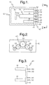
- FIG. 1 - 3 illustrate an embodiment of the present invention.
- a first expression of the embodiment shown in the figures is for an electric mechanical brake assembly 10 including an electric-mechanical-brake-caliper housing 12, an electric-mechanical-brake ballscrew subassembly 14, first and second electric motors 16 and 18, and at least three gears 20-28.
- the ballscrew subassembly 14 is at least partially disposed within the housing 12, has a rotatable actuation shaft 30, and has a linearly-movable member 32 which is driven by the actuation shaft 30 and which is attachable to a brake pad 34.
- the first electric motor 16 has a first drive shaft 36
- the second electric motor 18 has a second drive shaft 38.
- the at-least-three gears 20-28 operatively connect the first and second drive shafts 36 and 38 of the first and second electric motors 16 and 18 to the actuation shaft 30 of the ballscrew subassembly 14.
- the brake pad 34 is a vehicle brake pad.
- the vehicle brake pad is an inner brake pad of an automotive vehicle.
- the operation of an electric-mechanical-brake ballscrew subassembly to move a brake pad in an electric-mechanical-brake-caliper housing of a motor vehicle is well known.
- the actuation member 30 includes a ballscrew and the linearly-movable member 32 includes a ballnut.
- Other applications including non-vehicle applications), other implementations, and other ballscrew subassembly designs are left to the artisan. It is noted that the terminology "ballscrew subassembly" includes all mechanical motion transfer devices which transfer rotation of a rotatable actuation shaft into linear movement of a linearly-movable member, as can be appreciated by those skilled in the art.
- the first and second drive shafts 36 and 38 of the first and second electric motors 16 and 18 are substantially parallel to the actuation shaft 30 of the ballscrew subassembly 14.
- the first and second electric motors 16 and 18 are shorter in axial length than the ballscrew subassembly 14.
- the first and second electric motors 16 and 18 are at least partially disposed (and in one variation are substantially completely disposed except for their drive shafts 36 and 38) within the housing 12 and are disposed alongside the ballscrew subassembly 14 (meaning that the electric motors 16 and 18 axially overlap the ballscrew subassembly 14).
- gear 20 is attached to the first drive shaft 36 of the first electric motor 16
- gear 22 is attached to the second drive shaft 38 of the second electric motor 18
- gear 24 is attached to the actuation shaft 30 of the ballscrew subassembly 14.
- Gear 26 is an idler gear operatively connecting gear 20 and gear 24
- gear 28 is an idler gear operatively connecting gear 22 and gear 24.
- Other gear arrangements are left to the artisan.
- a second expression of the embodiment shown in the figures is for an electric-mechanical-brake motor subassembly 40 including electric-mechanical-brake first and second electric motors 16 and 18, a motor plate 42, and at least three gears 20-28.
- the first electric motor 16 has a first drive shaft 36
- the second electric motor 18 has a second drive shaft 38.
- the first and second electric motors 16 and 18 are attached to the motor plate 42, and the motor plate 42 is attachable to an electric-mechanical-brake-caliper housing 12.
- the at-least-three gears 20-28 are operatively connectable to the first and second drive shafts 36 and 38 of the first and second electric motors 16 and 18 and to a rotatable actuation shaft 30, of an electric-mechanical-brake ballscrew subassembly 14 at least partially disposed within the housing 12, for the first and second drive shafts 36 and 38 to rotate the actuation shaft 30.
- the first and second drive shafts 36 and 38 of the first and second electric motors 16 and 18 are substantially parallel to the actuation shaft 30 of the ballscrew subassembly 14.
- the first and second electric motors 16 and 18 are shorter in axial length than the ballscrew subassembly 14.
- the first and second electric motors 16 and 18 are at least partially disposed (and in one variation are substantially completely disposed except for their drive shafts 36 and 38) within the housing 12 and are disposed alongside the ballscrew subassembly 14 (meaning that the electric motors 16 and 18 axially overlap the ballscrew subassembly 14).
- the motor plate 42 becomes a housing cover when attached to the housing 12.
- the motor plate 42 has an opening 44 to allow passage therethrough of the actuation shaft 30 of the ballscrew subassembly 14 so that the gear 24 can be attached to the actuation shaft 30.
- idler shafts 46 and 48 are rotatably attached to the motor plate 42, wherein gear 26 is attached to idler shaft 46 and gear 28 is attached to idler shaft 48.
Landscapes
- Engineering & Computer Science (AREA)
- General Engineering & Computer Science (AREA)
- Mechanical Engineering (AREA)
- Braking Arrangements (AREA)
Abstract
Description
Claims (16)
- An electric mechanical brake assembly (10) comprising:a) an electric-mechanical-brake-caliper housing (12);b) an electric-mechanical-brake ballscrew subassembly (14) at least partially disposed within the housing, having a rotatable actuation shaft (30), and having a linearly-movable member (32) which is driven by the actuation shaft and which is attachable to a brake pad (34);c) a first electric motor (16) having a first drive shaft (36);d) a second electric motor (18) having a second drive shaft (38); ande) at least three gears (20-28) operatively connecting the first and second drive shafts to the actuation shaft.
- The electric mechanical brake assembly of claim 1, wherein the first and second drive shafts are substantially parallel to the actuation shaft.
- The electric mechanical brake assembly of claim 2, wherein the first and second electric motors are shorter in axial length than the ballscrew subassembly.
- The electric mechanical brake assembly of claim 2, wherein the first and second electric motors are at least partially disposed within the housing and are disposed alongside the ballscrew subassembly.
- The electric mechanical brake assembly of claim 1, wherein the first and second electric motors are shorter in axial length than the ballscrew subassembly.
- The electric mechanical brake assembly of claim 5, wherein the first and second electric motors are at least partially disposed within the housing and are disposed alongside the ballscrew subassembly.
- The electric mechanical brake assembly of claim 1, wherein the first and second electric motors are at least partially disposed within the housing and are disposed alongside the ballscrew subassembly.
- An electric mechanical brake assembly (10) comprising:wherein the first and second drive shafts are substantially parallel to the actuation shaft,a) an electric-mechanical-brake-caliper housing (12) ;b) an electric-mechanical-brake ballscrew subassembly (14) at least partially disposed within the housing, having a rotatable actuation shaft (30), and having a linearly-movable member (32) which is driven by the actuation shaft and which is attachable to a brake pad (34);c) a first electric motor (16) having a first drive shaft (36);d) a second electric motor (18) having a second drive shaft (38); ande) at least three gears (20-28) operatively connecting the first and second drive shafts to the actuation shaft,
wherein the first and second electric motors are shorter in axial length than the ballscrew subassembly, and
wherein the first and second electric motors are at least partially disposed within the housing and are completely disposed alongside the ballscrew subassembly. - An electric-mechanical-brake motor subassembly (40) comprising:a) an electric-mechanical-brake first electric motor (16) having a first drive shaft (36);b) an electric-mechanical-brake second electric motor (18) having a second drive shaft (38);c) a motor plate (42), wherein the first and second electric motors are attached to the motor plate, and wherein the motor plate is attachable to an electric-mechanical-brake-caliper housing (12); andd) at least three gears (20-28) operatively connectable to the first and second drive shafts and to a rotatable actuation shaft (30), of an electric-mechanical-brake ballscrew subassembly (14) at least partially disposed within the housing, for the first and second drive shafts to rotate the actuation shaft.
- The electric-mechanical-brake motor subassembly of claim 9, wherein, when the motor plate is attached to the housing, the first and second drive shafts are substantially parallel to the actuation shaft.
- The electric-mechanical-brake motor subassembly of claim 10, wherein the first and second electric motors are shorter in axial length than the ballscrew subassembly.
- The electric-mechanical-brake motor subassembly of claim 10, wherein, when the motor plate is attached to the housing, the first and second electric motors are at least partially disposed within the housing and are disposed alongside the ballscrew subassembly.
- The electric-mechanical-brake motor subassembly of claim 9, wherein the first and second electric motors are shorter in axial length than the ballscrew subassembly.
- The electric-mechanical-brake motor subassembly of claim 13, wherein, when the motor plate is attached to the housing, the first and second electric motors are at least partially disposed within the housing and are disposed alongside the ballscrew subassembly.
- The electric-mechanical-brake motor subassembly of claim 9, wherein, when the motor plate is attached to the housing, the first and second electric motors are at least partially disposed within the housing and are disposed alongside the ballscrew subassembly.
- An electric-mechanical-brake motor subassembly (40) comprising:wherein, when the motor plate is attached to the housing, the first and second drive shafts are substantially parallel to the actuation shaft,a) an electric-mechanical-brake first electric motor (16) having a first drive shaft (36);b) an electric-mechanical-brake second electric motor (18) having a second drive shaft (38);c) a motor plate (42), wherein the first and second electric motors are attached to the motor plate, and wherein the motor plate is attachable to an electric-mechanical-brake-caliper housing (12); andd) at least three gears (20-28) operatively connectable to the first and second drive shafts and to a rotatable actuation shaft, of an electric-mechanical-brake ballscrew subassembly (14) at least partially disposed within the housing, for the first and second drive shafts to rotate the actuation shaft,
wherein the first and second electric motors are shorter in axial length than the ballscrew subassembly, and
wherein, when the motor plate is attached to the housing, the first and second electric motors are at least partially disposed within the housing and are completely disposed alongside the ballscrew subassembly.
Applications Claiming Priority (2)
| Application Number | Priority Date | Filing Date | Title |
|---|---|---|---|
| US137501 | 1993-10-15 | ||
| US10/137,501 US20030205437A1 (en) | 2002-05-02 | 2002-05-02 | Gear-driven electric mechanical brake assembly and motor subassembly therefor |
Publications (2)
| Publication Number | Publication Date |
|---|---|
| EP1359338A2 true EP1359338A2 (en) | 2003-11-05 |
| EP1359338A3 EP1359338A3 (en) | 2004-07-21 |
Family
ID=29215697
Family Applications (1)
| Application Number | Title | Priority Date | Filing Date |
|---|---|---|---|
| EP03076073A Withdrawn EP1359338A3 (en) | 2002-05-02 | 2003-04-14 | Gear-driven electric mechanical brake-assembly and motor subassembly therefor |
Country Status (2)
| Country | Link |
|---|---|
| US (1) | US20030205437A1 (en) |
| EP (1) | EP1359338A3 (en) |
Cited By (3)
| Publication number | Priority date | Publication date | Assignee | Title |
|---|---|---|---|---|
| CN104648347A (en) * | 2013-11-20 | 2015-05-27 | 现代自动车株式会社 | Actuator For Electrical Parking Brake System |
| WO2016016541A1 (en) | 2014-07-30 | 2016-02-04 | Chassis Brakes International B.V. | Vehicle brake actuator |
| CN114087302A (en) * | 2021-10-19 | 2022-02-25 | 中国科学院电工研究所 | Configuration control method and control system for electronic mechanical brake linear control system |
Families Citing this family (6)
| Publication number | Priority date | Publication date | Assignee | Title |
|---|---|---|---|---|
| KR20130117091A (en) * | 2012-04-17 | 2013-10-25 | 주식회사 만도 | Electronic parking brake |
| US20140034432A1 (en) * | 2012-08-03 | 2014-02-06 | Advics North America | Electric brake actuator for vehicles |
| US9476469B2 (en) * | 2014-01-22 | 2016-10-25 | Akebono Brake Industry Co., Ltd | Electric drum or drum-in-hat park brake |
| US9447830B2 (en) | 2014-06-06 | 2016-09-20 | Advics Co., Ltd. | Electric brake actuator for vehicles |
| KR102139586B1 (en) * | 2018-08-10 | 2020-07-30 | 주식회사 만도 | Brake actuator and electromechanical brake using the same and control method thereof |
| US11339842B2 (en) | 2019-03-26 | 2022-05-24 | Akebono Brake Industry Co., Ltd. | Brake system with torque distributing assembly |
Family Cites Families (3)
| Publication number | Priority date | Publication date | Assignee | Title |
|---|---|---|---|---|
| JPH10181578A (en) * | 1996-12-26 | 1998-07-07 | Akebono Brake Ind Co Ltd | Electric brake |
| DE19916955A1 (en) * | 1999-04-15 | 2000-10-19 | Bosch Gmbh Robert | Electromechanically operated brake unit for motor vehicle, consisting of three stepper type motor modules |
| FR2819469B1 (en) * | 2001-01-18 | 2003-02-28 | Sagem | ELECTROMECHANICAL BRAKE ACTUATOR WITH MULTIPLE DISCS FOR MEANS OF TRANSPORT, ESPECIALLY FOR AIRCRAFT |
-
2002
- 2002-05-02 US US10/137,501 patent/US20030205437A1/en not_active Abandoned
-
2003
- 2003-04-14 EP EP03076073A patent/EP1359338A3/en not_active Withdrawn
Cited By (8)
| Publication number | Priority date | Publication date | Assignee | Title |
|---|---|---|---|---|
| CN104648347A (en) * | 2013-11-20 | 2015-05-27 | 现代自动车株式会社 | Actuator For Electrical Parking Brake System |
| CN104648347B (en) * | 2013-11-20 | 2018-11-16 | 现代自动车株式会社 | Actuator for electronic brake system |
| WO2016016541A1 (en) | 2014-07-30 | 2016-02-04 | Chassis Brakes International B.V. | Vehicle brake actuator |
| US10890225B2 (en) | 2014-07-30 | 2021-01-12 | Chassis Brakes International B.V. | Vehicle brake actuator |
| CN114087302A (en) * | 2021-10-19 | 2022-02-25 | 中国科学院电工研究所 | Configuration control method and control system for electronic mechanical brake linear control system |
| WO2023065709A1 (en) * | 2021-10-19 | 2023-04-27 | 中国科学院电工研究所 | Configuration control method and control system for electronic mechanical brake-by-wire system |
| CN114087302B (en) * | 2021-10-19 | 2024-02-27 | 中国科学院电工研究所 | An electronic mechanical brake wire control system configuration control method and control system |
| US12427967B2 (en) | 2021-10-19 | 2025-09-30 | Institute Of Electrical Engineering, Chinese Academy Of Sciences | Configuration control method and control system for electronic mechanical brake-by-wire system |
Also Published As
| Publication number | Publication date |
|---|---|
| EP1359338A3 (en) | 2004-07-21 |
| US20030205437A1 (en) | 2003-11-06 |
Similar Documents
| Publication | Publication Date | Title |
|---|---|---|
| CN102165220B (en) | Electric linear actuator and electric brake device | |
| NL1011731C2 (en) | Actuator with compact gear reduction. | |
| JP6602306B2 (en) | Geared motor, drum brake, brake device, and disc brake | |
| US8136641B2 (en) | Actuating mechanism and brake assembly | |
| JP6557238B2 (en) | Actuator having gear-type transmission device subassembly, and drum brake and brake device including the same | |
| JP2004263711A (en) | Actuator and brake device | |
| CN115451045A (en) | Motor gear unit for disc brake device and disc brake device | |
| KR20020073502A (en) | Actuator unit and brake calliper | |
| US12139116B2 (en) | Disk brake | |
| JPH11513471A (en) | Improvements in car electrically operated disc brake assemblies | |
| US20030205437A1 (en) | Gear-driven electric mechanical brake assembly and motor subassembly therefor | |
| CN108367748A (en) | Small size electromechanical actuator for disk brake | |
| US20040124042A1 (en) | Electric mechanical brake assembly having a worm or cluster gear set | |
| JP2022515260A (en) | Reduction gearbox that provides ample comfort for drum brakes | |
| CN119042259B (en) | Electromechanical brake actuator assembly, electromechanical brake and vehicle | |
| US20040016607A1 (en) | Belt-driven electric mechanical brake assembly and motor subassembly therefor | |
| KR100554542B1 (en) | Electric control device for electronically controlled caliper brake | |
| CA2363082A1 (en) | Lifting device | |
| JP2019203518A (en) | Actuator for electric parking brake | |
| KR20140104518A (en) | Decelerator and motor brake with the same | |
| KR100554544B1 (en) | Electric control device for electronically controlled caliper brake | |
| KR100554543B1 (en) | Electric control device for electronically controlled caliper brake | |
| CN221497970U (en) | Brake driving device, brake and vehicle | |
| JP6641881B2 (en) | Vehicle brakes | |
| JP7722106B2 (en) | Electric braking device and manufacturing method thereof |
Legal Events
| Date | Code | Title | Description |
|---|---|---|---|
| PUAI | Public reference made under article 153(3) epc to a published international application that has entered the european phase |
Free format text: ORIGINAL CODE: 0009012 |
|
| AK | Designated contracting states |
Kind code of ref document: A2 Designated state(s): AT BE BG CH CY CZ DE DK EE ES FI FR GB GR HU IE IT LI LU MC NL PT RO SE SI SK TR |
|
| AX | Request for extension of the european patent |
Extension state: AL LT LV MK |
|
| PUAL | Search report despatched |
Free format text: ORIGINAL CODE: 0009013 |
|
| AK | Designated contracting states |
Kind code of ref document: A3 Designated state(s): AT BE BG CH CY CZ DE DK EE ES FI FR GB GR HU IE IT LI LU MC NL PT RO SE SI SK TR |
|
| AX | Request for extension of the european patent |
Extension state: AL LT LV MK |
|
| AKX | Designation fees paid | ||
| REG | Reference to a national code |
Ref country code: DE Ref legal event code: 8566 |
|
| STAA | Information on the status of an ep patent application or granted ep patent |
Free format text: STATUS: THE APPLICATION IS DEEMED TO BE WITHDRAWN |
|
| 18D | Application deemed to be withdrawn |
Effective date: 20050122 |