EP3173648B1 - Kupplungsvorrichtung mit verschleissausgleich, insbesondere für kraftfahrzeug - Google Patents
Kupplungsvorrichtung mit verschleissausgleich, insbesondere für kraftfahrzeug Download PDFInfo
- Publication number
- EP3173648B1 EP3173648B1 EP16197538.8A EP16197538A EP3173648B1 EP 3173648 B1 EP3173648 B1 EP 3173648B1 EP 16197538 A EP16197538 A EP 16197538A EP 3173648 B1 EP3173648 B1 EP 3173648B1
- Authority
- EP
- European Patent Office
- Prior art keywords
- wear
- diaphragm
- mobile
- detection
- compensation
- Prior art date
- Legal status (The legal status is an assumption and is not a legal conclusion. Google has not performed a legal analysis and makes no representation as to the accuracy of the status listed.)
- Active
Links
- 238000001514 detection method Methods 0.000 claims description 135
- 238000006243 chemical reaction Methods 0.000 claims description 69
- 230000009977 dual effect Effects 0.000 claims description 11
- 230000013011 mating Effects 0.000 claims 10
- 210000002105 tongue Anatomy 0.000 description 43
- 238000006073 displacement reaction Methods 0.000 description 21
- 239000000463 material Substances 0.000 description 13
- 210000000056 organ Anatomy 0.000 description 10
- 230000007246 mechanism Effects 0.000 description 9
- 238000013519 translation Methods 0.000 description 6
- 230000005540 biological transmission Effects 0.000 description 5
- 230000008878 coupling Effects 0.000 description 5
- 238000010168 coupling process Methods 0.000 description 5
- 238000005859 coupling reaction Methods 0.000 description 5
- 238000012546 transfer Methods 0.000 description 4
- 240000000966 Allium tricoccum Species 0.000 description 3
- 230000036316 preload Effects 0.000 description 3
- 238000005086 pumping Methods 0.000 description 3
- 230000000284 resting effect Effects 0.000 description 3
- 238000012937 correction Methods 0.000 description 2
- 230000001186 cumulative effect Effects 0.000 description 2
- 230000000694 effects Effects 0.000 description 2
- 229940082150 encore Drugs 0.000 description 2
- 230000007257 malfunction Effects 0.000 description 2
- 230000004048 modification Effects 0.000 description 2
- 238000012986 modification Methods 0.000 description 2
- 238000013459 approach Methods 0.000 description 1
- 230000008859 change Effects 0.000 description 1
- 239000000470 constituent Substances 0.000 description 1
- 230000001627 detrimental effect Effects 0.000 description 1
- 238000009420 retrofitting Methods 0.000 description 1
Images


Classifications
-
- F—MECHANICAL ENGINEERING; LIGHTING; HEATING; WEAPONS; BLASTING
- F16—ENGINEERING ELEMENTS AND UNITS; GENERAL MEASURES FOR PRODUCING AND MAINTAINING EFFECTIVE FUNCTIONING OF MACHINES OR INSTALLATIONS; THERMAL INSULATION IN GENERAL
- F16D—COUPLINGS FOR TRANSMITTING ROTATION; CLUTCHES; BRAKES
- F16D13/00—Friction clutches
- F16D13/58—Details
- F16D13/75—Features relating to adjustment, e.g. slack adjusters
- F16D13/757—Features relating to adjustment, e.g. slack adjusters the adjusting device being located on or inside the clutch cover, e.g. acting on the diaphragm or on the pressure plate
-
- F—MECHANICAL ENGINEERING; LIGHTING; HEATING; WEAPONS; BLASTING
- F16—ENGINEERING ELEMENTS AND UNITS; GENERAL MEASURES FOR PRODUCING AND MAINTAINING EFFECTIVE FUNCTIONING OF MACHINES OR INSTALLATIONS; THERMAL INSULATION IN GENERAL
- F16D—COUPLINGS FOR TRANSMITTING ROTATION; CLUTCHES; BRAKES
- F16D13/00—Friction clutches
- F16D13/58—Details
-
- F—MECHANICAL ENGINEERING; LIGHTING; HEATING; WEAPONS; BLASTING
- F16—ENGINEERING ELEMENTS AND UNITS; GENERAL MEASURES FOR PRODUCING AND MAINTAINING EFFECTIVE FUNCTIONING OF MACHINES OR INSTALLATIONS; THERMAL INSULATION IN GENERAL
- F16D—COUPLINGS FOR TRANSMITTING ROTATION; CLUTCHES; BRAKES
- F16D66/00—Arrangements for monitoring working conditions, e.g. wear, temperature
- F16D66/02—Apparatus for indicating wear
- F16D66/021—Apparatus for indicating wear using electrical detection or indication means
- F16D66/022—Apparatus for indicating wear using electrical detection or indication means indicating that a lining is worn to minimum allowable thickness
- F16D66/023—Apparatus for indicating wear using electrical detection or indication means indicating that a lining is worn to minimum allowable thickness directly sensing the position of braking members
- F16D66/024—Sensors mounted on braking members adapted to contact the brake disc or drum, e.g. wire loops severed on contact
-
- F—MECHANICAL ENGINEERING; LIGHTING; HEATING; WEAPONS; BLASTING
- F16—ENGINEERING ELEMENTS AND UNITS; GENERAL MEASURES FOR PRODUCING AND MAINTAINING EFFECTIVE FUNCTIONING OF MACHINES OR INSTALLATIONS; THERMAL INSULATION IN GENERAL
- F16D—COUPLINGS FOR TRANSMITTING ROTATION; CLUTCHES; BRAKES
- F16D21/00—Systems comprising a plurality of actuated clutches
- F16D21/02—Systems comprising a plurality of actuated clutches for interconnecting three or more shafts or other transmission members in different ways
- F16D21/06—Systems comprising a plurality of actuated clutches for interconnecting three or more shafts or other transmission members in different ways at least two driving shafts or two driven shafts being concentric
- F16D2021/0607—Double clutch with torque input plate in-between the two clutches, i.e. having a central input plate
-
- F—MECHANICAL ENGINEERING; LIGHTING; HEATING; WEAPONS; BLASTING
- F16—ENGINEERING ELEMENTS AND UNITS; GENERAL MEASURES FOR PRODUCING AND MAINTAINING EFFECTIVE FUNCTIONING OF MACHINES OR INSTALLATIONS; THERMAL INSULATION IN GENERAL
- F16D—COUPLINGS FOR TRANSMITTING ROTATION; CLUTCHES; BRAKES
- F16D66/00—Arrangements for monitoring working conditions, e.g. wear, temperature
- F16D2066/008—Arrangements for monitoring working conditions, e.g. wear, temperature of clutches
-
- F—MECHANICAL ENGINEERING; LIGHTING; HEATING; WEAPONS; BLASTING
- F16—ENGINEERING ELEMENTS AND UNITS; GENERAL MEASURES FOR PRODUCING AND MAINTAINING EFFECTIVE FUNCTIONING OF MACHINES OR INSTALLATIONS; THERMAL INSULATION IN GENERAL
- F16D—COUPLINGS FOR TRANSMITTING ROTATION; CLUTCHES; BRAKES
- F16D2500/00—External control of clutches by electric or electronic means
- F16D2500/50—Problem to be solved by the control system
- F16D2500/502—Relating the clutch
- F16D2500/50233—Clutch wear adjustment operation
Definitions
- the present invention relates to a clutch device to take up wear, especially for a motor vehicle.
- a clutch device conventionally comprises a reaction plate, a movable pressure plate and a friction disk mounted between said reaction and pressure plates.
- the movement of the pressure plate is controlled by a diaphragm, itself controlled by a clutch abutment.
- the pressure plate is thus movable between a clutch position in which the friction disk is clamped between said pressure and reaction plates, and a disengaging position in which the friction disk is released.
- the use of the clutch device causes wear of the friction disc liners and the counter-materials of the associated pressure and reaction plates. This results in a variation of the position of the pressure plate relative to the associated diaphragm and / or with respect to the reaction plate, generating a variation of the friction disk clamping force and a modification of the licking point and the stroke of the clutch stop. It is recalled that the licking point is the position from which a torque can be transmitted through the clutch device.
- a clutch device with catch-up wear is known from the document FR 2 780 119 .
- This device comprises a lid inside which is mounted a pressure plate intended to bear against a friction disk, a diaphragm inserted between the lid and the pressure plate, serving to actuate the pressure plate between a fully engaged position in which said pressure plate is pushed against the friction disc, and a fully disengaged position wherein said pressure plate is spaced apart from the friction disc by biasing means of the pressure plate.
- Means for catching the wear of the friction disk are interposed between the diaphragm and the pressure plate, and comprise at least one retrofit member movable in a determined range and having a ramp cooperating with a counter-ramp turned on the side of the diaphragm. pressure plate, so as to adjust the distance between the diaphragm and the pressure plate and compensate the wear of the friction disc according to the angular position of the ramp relative to the counter-ramp.
- the device further comprises wear detecting means adapted to allow the displacement of the movable catch member in case of wear of the friction disc and able to prevent such displacement when this wear is not sufficient, said detection means comprising at least one movable detection member, in a given range, with respect to the catch member and having a ramp cooperating with a counter-ramp turned on the side of the pressure plate.
- the device comprises a pressure member constraining the ramps of said movable members against the associated counter ramps, the pressing member being adapted to cooperate with a fixed stop, so as to release said movable members when a wear of the friction disc is detected.
- the movable catch member is biased by means of a spring, so as to catch the clearance between the latter and the pressing member, when said movable catch member is released by the pressure member and the diaphragm . Furthermore, the mobile detection member is biased by another spring so as to make up the clearance between the latter and the pressing member, when said movable detection member is released by the pressing member and the diaphragm.
- the assembly is subjected, alternately, to successive phases of clutch and disengagement.
- the diaphragm presses on the pressure plate, via the play-catching member.
- the pressure plate is returned to its disengaged position by means of return means generally taking the form of elastically deformable tongues.
- the pressing member constantly holds the detection member and the catch member resting on the disk pressure: said organs are immobilized.
- the pressure member bears on the stop and a play is created between the pressing member and the detection member.
- the latter is constrained by a spring, it is moved to fill the game above.
- the force applied by the diaphragm on the catch member prevents the displacement of the latter, by pressing and friction on the pressure plate.
- the return tongues of the pressure plate tend to press the pressure plate against the play catch member, and the play catch member against the diaphragm.
- the force exerted by the return tongues is relatively small so as to allow, despite the friction in play, a displacement of the play catch member, under the effect of the stress applied by the corresponding spring. This movement makes it possible to make up the clearance between the pressing member and the catching member. This compensates for the wear of the friction plate as well as the wear of the counter-materials of the associated pressure and reaction plates.
- the diaphragm releases the movable detection member and prevents the movement of the mobile retraction member, in fully engaged position, and the diaphragm releases the mobile retraction member and prevents the displacement of the movable detection member.
- the diaphragm in fully disengaged position, the diaphragm always bearing on at least one of said movable members between its fully engaged positions and fully disengaged.
- the biasing means of the pressure plate can exert a major force, this force being taken up by the mobile retraction member and then by the diaphragm, or by the movable detection member and then by the diaphragm, depending on the position of the diaphragm. Indeed, during their movements, said movable members are not subjected to the force exerted by the biasing means of the pressure plate and it is therefore possible to easily solicit their displacement, in case of wear.
- biasing means of the pressure plate exerting a large force such as for example spring tongues having a high stiffness, allows to limit the transmission of axial vibrations and to avoid the pumping phenomena of the pressure plate.
- the movable detection member and the movable catch member are biased by elastic members, for example traction springs.
- At least one circumferentially extending first tension spring is mounted between the sensing member and the pressure plate, or between the sensing member and a cover rotatably coupled to the pressure plate.
- Second circumferentially extending traction springs are mounted between the sensing member and the catch member. These second springs provide the motorization function of the catch member with respect to the sensing member.
- a double clutch allows in particular to alternately couple the motor shaft of the vehicle with two coaxial input shafts of a gearbox, which can be of the robotic type.
- a dual clutch allows to change gears while maintaining the transmission of a torque engine to the vehicle wheels.
- the two clutches are respectively associated with even and odd gear ratios.
- a first clutch is disengaged while the second clutch is engaged, so that the engine torque is progressively transferred from the first to the second clutch.
- Each clutch comprises a mechanism comprising a diaphragm for cooperating with a pressure plate integral in rotation with the cover and the motor shaft.
- Each diaphragm is movable by means of a corresponding clutch abutment, between a rest position and an active position.
- the active position of the diaphragm corresponds to a coupling or decoupling of the shafts of the engine and the gearbox and the rest position of the diaphragm corresponds to a decoupling or a coupling of these shafts.
- These are respectively a normally open clutch and a normally closed clutch.
- At least one of the clutches is of the normally open type.
- the clutch stop is controlled by an actuator controlled by an electronic computer to exert a predetermined force on the diaphragm and move it over a given distance.
- each clutch biased by the corresponding diaphragm, is intended to clamp a friction disc on a corresponding reaction plate.
- a reaction plate may be provided for each clutch.
- Each friction disk is rotatably connected to an input shaft of the gearbox and each reaction plate is for example integral in rotation with a flywheel connected to the motor shaft.
- the use of the clutches causes wear of the friction linings of the friction discs as well as the counter-materials of the pressure and associated reaction plates. This results in a variation of the position of each pressure plate with respect to the associated diaphragm and / or the reaction plate, generating a variation of the friction disk clamping force and a modification of the licking point and the stroke at the clutch stop.
- the licking point is the position from which a portion of the engine torque is transmitted to the gearbox shaft when closing the clutch.
- the double clutch may comprise both wear compensating mechanisms equipping the first clutch and a mechanism equipping the second clutch.
- the patent application FR 3,009,592 discloses in particular the use of a first wear-compensating mechanism equipping the first clutch and a second wear-compensating mechanism equipping the second clutch.
- a double clutch comprising a reaction plate intended to be coupled in rotation to a driving shaft, a first and a second friction disk, intended to be coupled respectively to a first and a second driven shaft, a first and second pressure plates, respectively actuated by a first and a second diaphragm so as to clamp or release the first and second friction disc on the reaction plate, the first pressure plate being fixedly connected to a movable cover; translation with respect to the reaction plate, and being actuated by pressing the first diaphragm on the movable cover, first detection means and catch-up of the wear of the first friction disc being interposed between the first diaphragm and the movable cover, second means for detecting and catching the wear of the second friction disc, being interposed between the second diaphragm me and the second pressure plate
- the movable lid In operation, the movable lid is subjected to significant mechanical stresses that can generate deformities making it difficult to properly position the constituent elements of the first detection and wear-compensating means. This can appreciably affect the proper functioning of the first means of detecting and compensating for wear.
- the invention proposes a wear-catching clutch device intended to guarantee the correct position of the detection and wear-compensating members in order to avoid any over-compensation or under-compensation of the wear.
- the abutment member being connected to the pressing member in an area between the sensing member and the catching member, limits the tilting effect of the pressure member, such a tilting having an influence on the positions of the actual bearing areas of the pressing member on the sensing member and / or the catch member.
- the aforementioned characteristic thus makes it possible to control the position of said movable members, so as to guarantee the proper functioning of the corresponding wear detecting and compensating means and to avoid overcompensation or under-compensation of wear.
- the stop member may be connected to the pressure member in an area located radially midway between the sensing member and the catch member.
- the pressing member may exert a pressure force distributed between the sensing member and the catch member and the axial component of this force along the axis X may be applied to an application radius located between the sensing member and the catch-up member.
- the movable catch member and the movable detection member may be concentric.
- the stop member may comprise an end connected to a fixed or movable part of the clutch device, and an end connected to the pressing member.
- the detection member and the catch member may comprise at least one zone provided with bulges in which said movable members are locally spaced apart from one another in the radial direction, the pressing member pressing the corresponding ends of the movable members at said area provided with bulges.
- the end of the abutment member which is connected to the pressure member may be accommodated in said area provided with bulges.
- the pressing member may comprise at least one resilient tongue whose one end is adapted to bear on the movable detection member or on the corresponding mobile retraction member.
- Each clutch is thus equipped with wear compensating means having a reduced axial and radial bulge.
- the size of the double clutch is therefore significantly reduced.
- the positioning of the first and second wear detection and compensating means makes it possible to better control the positioning of the wear detection means and the catch-up means of the wear detection means. corresponding wear. This makes it possible to guarantee the correct operation of said means of detecting and compensating for wear.
- the first diaphragm or the second diaphragm may release the movable detection member and prevent the mobile retraction member from moving in a fully engaged position, the first diaphragm or second diaphragm being able to release the movable retractor and prevent displacement. of the mobile detection element, in position completely disengaged, the first diaphragm or the second diaphragm always bearing on at least one of said movable members between its fully engaged positions and fully disengaged.
- Each movable detection member may be in the form of a ring having an end adapted to serve to support the corresponding diaphragm and an end comprising at least one ramp extending circumferentially, cooperating with the associated counter ramp on the side fixed cover or second pressure plate.
- the movement of the ramp of the movable detection member with respect to the associated counter ramp can thus be obtained by pivoting of the movable detection member.
- each mobile catch member may be in the form of a ring having an end adapted to serve to support the corresponding diaphragm and an end having at least one ramp extending circumferentially, cooperating with the counter-ramp associated turned on the side of the fixed cover or the second pressure plate.
- the movement of the ramp of the mobile catch member with respect to the associated counter ramp can thus be obtained by pivoting the movable catch member.
- the stop member may comprise an end connected to the fixed cover or the movable cover, and an end connected to the pressing member.
- the abutment member may comprise an end adapted to bear on the movable cover or on the fixed cover in case of wear, and an end fixed or bearing on the pressing member.
- the stop member may comprise an end attached to the movable cover or the fixed cover in case of wear, and an end bearing against the pressing member.
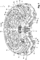
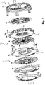
- a dual wear-catching clutch 1 according to one embodiment of the invention is shown in FIGS. Figures 1 to 4 .
- This is intended to couple a motor with a first and a second input shaft of a gearbox (not shown).
- the axis of the double clutch is referenced X.
- the double clutch 1 comprises first and second clutches 2a, 2b (also called clutch mechanisms) for passing reports of different parities.
- the first clutch 2a comprises a first pressure plate 3a and a reaction plate 4 between which a first friction disc 5a extends.
- the first pressure plate 3a is rotatably coupled to the reaction plate 4 and is movable in translation with respect to the latter, between an engaged position and a disengaged position, in which it closes the first friction disc 5a on the reaction plate 4, or respectively releases the first friction disc 5a.
- the reaction plate 4 is fixed on a cover 6 called fixed cover, itself intended to be coupled to the motor shaft.
- the first friction disc 5a is intended to be coupled to the first input shaft of the gearbox.
- the motor shaft is coupled to the first input shaft of the gearbox.
- the first pressure plate 3a is fixed on a cover 7 movable in translation relative to the reaction plate 4 and the fixed cover 6, and extending forwardly.
- First elastic return tongues 8a are mounted between the first pressure plate 3a and the reaction plate 4.
- the first clutch 2a further comprises a first diaphragm 9a in the form of an elastic annular sheet, and is pivotally mounted around bearing zones 10 of the movable cover 7.
- the control of the first clutch 2a is conventionally done by means of a first clutch abutment (not shown) cooperating with the radially inner periphery of the first diaphragm 9a.
- the first diaphragm 9a forms a lever transmitting the force applied by the first control stop to the first pressure plate 3a, via the movable cover 7.
- the first diaphragm 9a In order to allow effective clamping of the first friction disc 3a, the first diaphragm 9a is pre-loaded at rest. Without this pre-charge, the first diaphragm 9a would, at rest, in a state of elasticity requiring a start of travel of the relatively large first control stop to apply an effective clamping force on the first friction disc 3a.
- the first clutch abutment When the first clutch abutment is actuated, it balances the pre-charge of the first diaphragm 9a before starting the tightening of the first disc. friction 3a.
- the pre-charge of the first diaphragm 9a makes it possible to reduce the approach stroke of the first clutch abutment in order to clamp the first friction disk 3a, and to always have a minimum pre-load force, for example on the ball bearing of the first clutch abutment and the ball bearing which supports the double clutch 1. This increases the life of said bearings and limits the vibration of the double clutch 1.
- the first clutch 2a is of the normally open type.
- the rest position of the first diaphragm 9a therefore corresponds to a disengaged state of the first clutch 2a.
- the first diaphragm 9a preferably has a portion of the Belleville washer type for returning the first diaphragm 9a to its rest position.
- the first diaphragm 9a In the rest position of the first diaphragm 9a, that is to say when the first stop does not exert or little effort on the first diaphragm 9a, the first diaphragm 9a therefore does not exert (or little) stress on the first pressure plate 3a.
- the first pressure plate 3a is separated from the reaction plate 4 by means of the elastic tongues 8a, so as to release the first friction disc 5a.
- the second clutch 2b has a second pressure plate 3b, and a second friction disk 5b extending radially between the reaction plate 4 and the second pressure plate 3b.
- the same reaction plate 4 is thus used for the two clutches 2a, 2b, each friction disc 5a, 5b being disposed on the side of one of the two radial bearing surfaces of the reaction plate 4.
- Second elastic tongues of recall 8b are mounted between the second pressure plate 3b and the reaction plate 4.
- the second pressure plate 3b is coupled in rotation to the reaction plate 4 and is movable in translation relative thereto, between an engaged position and a disengaged position, in which it clamps the second friction disk 5b to the reaction plate 4, or releases the second friction disk 5b, respectively.
- the second friction disc 5b is coupled to the second input shaft of the gearbox.
- the motor shaft is coupled to the second input shaft of the gearbox.
- the second clutch 2b further comprises a second diaphragm 9b in the form of an elastic annular sheet whose radially outer periphery is pivotally mounted relative to the fixed cover.
- An elastic member 11 maintains the radially outer periphery of the second diaphragm bearing 12 on the fixed lid 6 ( figure 4 ).
- the control of the second clutch 2b is conventionally done by means of a second clutch abutment (not shown) cooperating with the radially inner periphery of the second diaphragm 9b, via a force transmission member (not shown). ).
- the second diaphragm 9b forms a lever transmitting the force applied by the second clutch abutment to the second pressure plate 3b, to allow effective clamping of the second friction disc 5b.
- the second clutch 2b is also of the normally open type. In the rest position of the second diaphragm 9b, that is to say when the second control stopper exerts little or no effort on the second diaphragm 9b, the second diaphragm 9b does not exert (or little) stress on the second pressure plate 3b.
- the second pressure plate 3b is spaced from the reaction plate 4 via the elastic tongues 8b, so as to release the second friction disk 3b.
- the fixed cover 6 comprises, from the rear to the front, radial flanges 6a for fixing on the reaction plate 4, connected to an annular portion 6b surrounding, at least in part, the second pressure plate 3b, the second friction disc 5b and / or the second diaphragm 9b. Said annular portion 6b is extended by an annular portion 6c extending radially inwards.
- the movable cover 7 has a radially outer portion 7a extending forwardly from the first pressure plate 3a and partially surrounding the fixed cover 6, extended at the front by a radially extending portion 7b. inside and serving to support the first diaphragm 9a.
- the first clutch 2a is equipped with first detection and wear compensating means.
- the first catch and wear detecting means equipping the first clutch 2a are interposed axially between the fixed cover 6 and the first diaphragm 9a, more precisely interposed axially between the radial portion 6c of the fixed cover 6 and the first diaphragm 9a.
- the first means of catching up and detecting wear comprise a first movable retraction member 13a in the form of a ring having an end against which the first diaphragm 9a is able to bear, and an end comprising at least a ramp 14a extending circumferentially, cooperating with an associated counter ramp 15a formed directly on the radial portion 6c of the fixed cover 6 (see FIG. figure 6 for example).
- the counter ramp 15a may be formed by an independent piece and fixed on the fixed cover 6.
- the first catch-up and wear detection means also comprise a first movable detection member 16a in the form of a ring having one end against which the first diaphragm 9a is able to come into abutment, and an end comprising less a ramp 17a extending circumferentially, cooperating with the counter-ramp 15a of the radial portion 6c of the fixed cover 6 (see figure 6 for example).
- the angle of the ramps 14a, 17a of said movable members 13a, 16a and of the counter ramp 15a of the fixed cover 6 is between 2 and 20 °
- the two movable members 13a, 16a are concentric and separated from each other, the first detection member 16a being located radially outside the first wear-compensating member 13a.
- the respective positions of said movable members 13a, 16a can be reversed. Note however that the possibility of inversion of the movable members 13a, 16a is related to the internal architecture of the mechanism.
- Centering means such as for example pads, ensure the proper positioning of the movable members 13a, 16a.
- a first elastic member 18a such as for example a circumferentially extending tension spring, is mounted between the first detection member 16a and the fixed cover 6.
- a second elastic member 19a such as for example a pin-shaped spring, is mounted between the first detection member 16a and the first catch member 13a.
- the length of the first spring 18a is important, so as to be able to solicit the displacement of the first detection member 16a over a wide angular range (for example of the order of 120 °).
- the first clutch 2a also comprises at least one first pressing member 20a ( figure 2 ) is in the form of an elastic tongue exerting an axial force.
- Said tongue 20a is fixed to the fixed cover 6, at a first end, and is able to bear, at a second end, on the first detection member 16a and possibly on the first wear compensating member 13a, so that to constrain them in bearing on the radial part 6c of the fixed cover 6.
- the pressing member 20a exerts a pressure force distributed between the sensing member 16a. and the catch member 13a.
- the axial component of this force along the X axis is applied to an application radius located between the detection member 16a and the catch member 13a.
- An abutment member 21a is fixed on the second end of said tongue 20a.
- the stop member 21a has the general shape of a stud.
- the stop stud 21a has in particular a first end 22a ( figure 4 ) fixed, for example by riveting, radially between the first sensing member 16a and the first wear compensating member 13a, preferably radially midway between said movable members 13a, 16a, and a second cylindrical end 23a forming a enlarged head of larger dimension than the rest of the stud 21a and defining a shoulder.
- the abutment member 21a passes through a hole in the movable cover 7 and is able to bear against a radial bottom surface formed by a recess 24 formed in the movable cover 7.
- the enlarged head 23a of the abutment member 21a is intended to bear against the bottom surface of the counterbore 24 when the displacement of the first pressure plate 3a is important, that is to say when there is a significant wear of the lining of the first friction disc 5a and / or of the counter-materials of the first pressure plate 3a and the reaction plate 4.
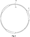
- these may comprise at least one zone 25 in which they are spaced apart. other, as illustrated in figure 5 .
- the movable members 13a, 16a and have, in front view, a generally circular shape with at least one zone 25 provided with bulges in which the movable members 13a, 16a are locally spaced from each other in the radial direction, the second end of the tongue 20a pressing against the corresponding secondary ends of the movable members 13a, 16a at one of the zones 25.
- the first clutch can then comprise three tabs 20a, each equipped with a stop member 21a of structure as described above.
- the three zones 25 are evenly distributed over the entire circumference and are therefore angularly offset by 120 °.
- the first means of catching up and detecting wear are inoperative when the linings of the first friction disk 5a are not or little worn out and the counter-materials of the first pressure plate 3a and the associated reaction plate 4 are not not worn, for example when the cumulative axial wear is less than 0.05 mm.
- FIGS 8 to 11 illustrate the case where the lining of the first friction disc 5a (or the counter-materials of the first pressure plate 3a and the reaction plate 4) have a high wear, which must be made up to avoid a malfunction of the first clutch 2a.
- the head 23a of the abutment member 21a abuts on the bottom surface of the countersink 24 of the movable cover 7, in fully engaged position, so that the second end of the elastic tongue 20a is detached from the secondary end corresponding first detection member 16a.
- a game j1 is formed between said secondary end of the first detection member 16a and the second end of the tongue 20a.
- the first detection member 16a which is then no longer subjected to an axial force, is rotated by the first elastic member 18a, so as to at least partially fill the clearance j1 ( figure 9 ). During this rotation, the second elastic member 19a is constrained.
- the rotation of the first detecting member 16a is stopped when the corresponding secondary end of the first detecting member 16a bears again on the second end of the tongue 20a. It will be noted that during this phase, the first catch member 13a is held in abutment on the fixed cover 6 by the first diaphragm 9a. It is immobilized in rotation relative to the fixed cover 6.
- the first diaphragm 9a transfers its support from the first catch member 13a to the first detection member 16a.
- the Figures 10 and 11 are views illustrating the positions of these elements during such a transfer.
- the first pressure plate 3a is spaced from the reaction plate 4 by means of the corresponding return tongues 8a, so as to release the first friction disk 5a.
- the first diaphragm 9a As illustrated in figure 10 when the first diaphragm 9a is in the fully disengaged position, it completely releases the first catch member 13a. In this position, the first detection member 16a is held fixed in rotation by pressing on the first diaphragm 9a and on the fixed cover 6. Moreover, the head 23a of the stop member 21a is spaced from the bottom surface of the counterbore 24 of the movable cover 7 and the second end of the movable tab 20a is spaced from a game j2 with respect to the corresponding second end of the first catch member 13a.
- the first catch member 13a constrained by the second elastic member 19a, is thus rotated as shown in FIG. figure 11 , so as to fill all or part of the game j2 between said first catch member 13a and the tongue 20a.
- the pivoting of the first catch member 13a and the first sensing member 16a relative to the fixed cover 6 allows, via the ramps 14a, 17a and against the ramp 15a, to increase the axial distance between the fixed cover 6 and the bearing area of the first diaphragm 9a on said members 13a, 16a, which makes it possible to progressively compensate for the wear of the linings of the first friction disc 5a and / or the wear of the counter-materials of the first pressure plate 3a and reaction plate 4.
- Such a structure also makes it possible to maintain the operating angle of the first diaphragm 9a, so as to maintain a constant pre-load force and reduce the mechanical stresses.
- the second clutch 2b is equipped with second means of catching up and detecting wear.
- the second catch-up and wear detection means equipping the second clutch 2b are interposed axially between the second diaphragm 9b and the second pressure plate 3b.
- the second catch-up and wear detection means comprise a second mobile catch-up member 13b in the form of a ring having one end against which the second diaphragm 9b is able to bear, and an end comprising at least a ramp 14b extending circumferentially, cooperating with an associated counterbeam 15b formed directly on the second pressure plate 3b.
- the second catch-up and wear detection means also comprise a second mobile detection member 16b in the form of a ring having one end against which the second diaphragm 9b is able to come into abutment, and a second end comprising at least one ramp 17b extending circumferentially, cooperating with the counter-ramp 15b of the second pressure plate 3b.
- the angle of the ramps 14b, 17b of said movable members 13b, 16b and of the counter-ramp 15b of the second pressure plate 3b is between 2 and 20 °.
- the two movable members 13b, 17b are concentric and separated from each other for example by centering and spacing pins.
- the second mobile detection member 16b is located radially outside the second corresponding mobile retraction member 13b.
- the respective positions of said movable members 13b, 16b can be reversed.
- a first circumferentially extending first tension spring 18b is mounted between the second sensing member 16b and the second pressure plate 3b.
- a second spring such as for example a pin-shaped spring 19b, is mounted between the second detection member 16b and the second catch member 13b.
- the length of the first spring 18b is important, so as to be able to bias the displacement of the second detection member 16b over a wide angular range (for example of the order of 120 °).
- the second clutch 2b also comprises at least one second pressing member 20b in the form of an elastic tongue exerting an axial force.
- Said tongue 20b is fixed to the pressure plate 3b at a first end and bears, at a second end, on the corresponding secondary end of the second detection member 16b and possibly on the second wear compensating member 13b , so as to constrain bearing on the second pressure plate 3b.
- An abutment member 21b is attached to the second end of said tab 20b.
- the abutment member 21b has the general shape of a stud.
- the abutment stud 21b comprises in particular a first end 22b fixed, for example by riveting, radially between the second detection member 16b and the second wear-catching member 13b, preferably radially halfway between said movable members 13b. , 16b, and a second cylindrical end 23b forming an enlarged head of larger dimension than the rest of the stud 21b and defining a shoulder.
- the abutment member 21b passes through a hole in the fixed cover 6 and is able to bear against a radial surface of the fixed cover 6.
- the enlarged head 23b of the abutment member 21b is intended to rest on the corresponding radial surface when the displacement of the second pressure plate 3b is large, that is to say when there is wear. important seals of the second friction disc 5b and / or counter-materials of the second pressure plate 3b and the reaction plate 4.
- the second catch-up and wear-detection means are inoperative when the linings of the second friction disc 5b are not or little worn out and the counter-materials of the second pressure plate 3b and the reaction plate 4 associated with them are not not worn, for example when the cumulative axial wear is less than 0.05 mm.
- the second end of the resilient tongue 20b and / or the second diaphragm 9b maintains the second sensing member 16b and the second catch member 13b resting on the second turntable. pressure 3b, regardless of the operating phase of the second clutch 2b (clutch / clutch).
- the resistive torque generated by the friction between said members 13b, 16b and the second pressure plate 3b is greater than the torque exerted by the springs 18b, 19b.
- Said members 13b, 16b are thus immobilized in rotation relative to the second pressure plate 3b, whatever the operating phase of the second clutch 2b.
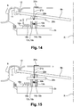
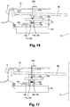
- FIGS 14 to 17 illustrate the case where the linings of the second friction disc 5b (or the counter-materials of the second pressure plate 3b and the reaction plate 4) have a high wear, which must be made up to avoid a malfunction second clutch 2b.
- the second detection member 16b which is then no longer subjected to an axial force, is rotated by the first elastic member 18b, so as to at least partially fill the game I1 ( figure 9 ). During this rotation, the second elastic member 19b is constrained.
- the rotation of the second detection member 16b is stopped when the corresponding secondary end of the second detection member 16b bears again on the second end of the tongue 20b. It will be noted that during this phase, the second catch member 13b is held in abutment on the second pressure plate 3b by the second diaphragm 9b. It is therefore immobilized in rotation relative to the second pressure plate 3b.
- the second diaphragm 9b transfers its support from the second catch member 13b to the second detection member 16a.
- the figures 15 and 16 are views illustrating the positions of these elements during such a transfer.
- the second pressure plate 3b is spaced from the reaction plate 4 via the corresponding return tongues 8b, so as to release the second friction disk 5b.
- the second catch member 13b constrained by the second elastic member 19b, is thus rotated as shown in FIG. figure 17 , so as to fill all or part of the game I2 between said second catch member 13b and the tongue 20b.
- the pivoting of the second catch member 13b and the second detection member 16b with respect to the second pressure plate 3b makes it possible, by means of the ramps 14b, 17b, and against the ramp 15b, to increase the axial distance between the second pressure plate 3b and the bearing zone of the second diaphragm 9b on said members 13b, 16b, which makes it possible to progressively compensate for the wear of the linings of the second friction disc 5b and / or the wear of the counter-materials of the second pressure plate 3b and the reaction plate 4.
- Such a structure also makes it possible to maintain the operating angle of the second diaphragm 9b, so as to maintain a constant pre-load force and reduce the mechanical stresses.
- the return means of the pressure plates 3a, 3b can exert a major effort, this effort being taken by the organ corresponding mobile retraction 13a, 13b then by the corresponding diaphragm 9a, 9b, or by the corresponding mobile detection member 16a, 16b and by the corresponding diaphragm 9a, 9b, depending on the position of said diaphragm 9a, 9b.
- said movable members 13a, 13b, 16a, 16b are not subjected to the force exerted by the return means 8a, 8b of the pressure plate 3a, 3b and it is therefore possible to request easily their displacement using the springs 18a, 18b, 19a, 19b, in case of wear.
- the tabs 20a, 20b forming the pressing members are respectively fixed to the fixed cover 6, and the pressure plate 3b and are therefore not subject to fatigue phenomena due to the clutch cycles and disengagement in operation.
- each abutment member 21a, 21b can be axially supported on the second end of the corresponding resilient tongue 20a, 20b, an attachment of the abutment member 21a, 21b of said resilient tongue 20a, 20b at the end. 22a, 22b not being mandatory.
- the abutment is oriented so that the second end of the tongue 20a, 20b of the corresponding detecting member 16a, 16b can be detached by means of the abutment member 21a, 21b, in case of wear.
- each stop member 21a, 21b is fixed relative to the movable cover 7 or relative to the fixed cover 6, respectively, the second end 22a, 22b of each stop member 21a, 21b being intended for come to bear axially on the second end of the corresponding resilient tongue 20a, 20b.
- the positioning of the first means for detecting and compensating for wear between the first diaphragm 9a and the fixed cover 6, on the one hand, and the positioning of the second detection and wear-compensating means between the second diaphragm 9b and the second second pressure plate 3b makes it possible to simplify the structure of the double clutch 1, to reduce the radial size of the latter and to better control the operation of said means for detecting and compensating for wear in positioning them between parts that are subjected to small deformations in operation. It thus better control the positions of the movable members 13a, 13b, 16a, 16b.
- each stop member 21a, 21b is connected to the second end of the corresponding tongue 20a, 20b, in an area located between the sensing member and the catch member, makes it possible to reduce as much as possible the deformation of this second end, so as to better control the axial positions of the various movable elements 13a, 13b, 16a, 16b, and therefore the resulting wear correction. This avoids or limits any overcompensation or under-compensation of wear.
Landscapes
- Engineering & Computer Science (AREA)
- General Engineering & Computer Science (AREA)
- Mechanical Engineering (AREA)
- Mechanical Operated Clutches (AREA)
Claims (15)
- Kupplungsvorrichtung mit Verschleißnachstellung, insbesondere für ein Kraftfahrzeug, die aufweist:- eine Reaktionsplatte (4), die dazu bestimmt ist, um eine Drehachse (X) mit einer Antriebswelle in Drehung gekoppelt zu werden,- eine Reibbeläge tragende Reibscheibe (5a, 5b), die dazu bestimmt ist, mit einer Abtriebswelle gekoppelt zu werden,- eine Druckplatte (3a, 3b), die von einer Membran (9a, 9b) betätigt wird, um die Reibscheibe (5a, 5b) auf der Reaktionsplatte (4) anzuziehen oder freizugeben,- Einrichtungen zur Erfassung und Nachstellung von Verschleiß, die den Verschleiß der Reibscheibe (5a, 5b) nachstellen können, wobei die Einrichtungen zur Erfassung und Nachstellung von Verschleiß zwischen einen bezüglich der Reaktionsplatte (4) ortsfesten Teil (6), zum Beispiel einen Deckel (6), und die Druckplatte (3a, 3b) eingelegt werden können, wobei die Einrichtungen zur Erfassung und Nachstellung von Verschleiß aufweisen:Verschleißnachstelleinrichtungen (13a, 13b), die zwischen die Membran (9a, 9b) und den ortsfesten Teil (6) oder zwischen die Membran (9a, 9b) und die Druckplatte (3a, 3b) eingelegt werden, wobei die Verschleißnachstelleinrichtungen mindestens ein Nachstellelement (13a, 13b) aufweisen, das in einem bestimmten Bereich beweglich ist und eine Rampe (14a, 14b) aufweist, die mit einer Gegenrampe (15a, 15b) zusammenwirkt, die zur Seite des ortsfesten Teils (6) oder der Druckplatte (3a, 3b) weist, um den Abstand zwischen der Membran (9a, 9b) und dem ortsfesten Teil (6) bzw. zwischen der Membran (9a, 9b) und der Druckplatte (3a, 3b) einzustellen und den entsprechenden Verschleiß abhängig von der Stellung der Rampe (14a, 14b) bezüglich der Gegenrampe (15a) zu kompensieren, Erfassungseinrichtungen des Verschleißes (16a, 16b), die die Verschiebung des beweglichen Nachstellelements (13a, 13b) im Fall eines Verschleißes erlauben und eine solche Verschiebung verhindern können, wenn dieser Verschleiß nicht ausreichend ist, wobei die Erfassungseinrichtungen mindestens ein Erfassungselement (16a, 16b) aufweisen, das in einem bestimmten Bereich bezüglich des beweglichen Nachstellelements (13a, 13b) beweglich ist und eine Rampe (17a, 17b) aufweist, die mit einer Gegenrampe (15a, 15b) zusammenwirkt, die zur Seite des ortsfesten Teils (6) oder der Druckplatte (3b) weist,mindestens ein Presselement (20a, 20b), das mindestens die Rampe (17a, 17b) des Erfassungselements (16a, 16b) gegen die zugeordnete Gegenrampe (15a, 15b) zwingt, wobei das Presselement (20a, 20b) mit einem ortsfesten Anschlag (21a, 21b) zusammenwirken kann, um das Erfassungselement (16a, 16b) freizugeben, wenn ein Verschleiß erfasst wird, wobei das bewegliche Nachstellelement (13a, 13b) so beaufschlagt wird, dass es sich verschiebt, wenn das bewegliche Nachstellelement (13a, 13b) von der Membran (9a, 9b) freigegeben wird,wobei das bewegliche Erfassungselement (16a, 16b) so beaufschlagt wird, dass es sich verschiebt und zumindest zum Teil das Spiel (j1, j'1) zwischen diesem und dem Presselement (20a, 20b) nachstellt, wobei das bewegliche Erfassungselement (16a, 16b) vom Presselement (20a, 20b) und von der Membran (9a, 9b) freigegeben wird,dadurch gekennzeichnet, dass sie ein mit dem Presselement (20a, 20b) verbundenes Anschlagelement (21a, 21b) aufweist, wobei das Anschlagelement (21a, 21b) konzipiert ist, das Presselement (20a, 20b) im Fall eines Verschleißes vom Erfassungselement (16a, 16b) und/oder vom Nachstellelement (13a, 13b) zu entfernen, wobei das Anschlagelement (21a, 21b) mit dem Presselement (20a, 20b) in einem Bereich verbunden ist, der sich radial zwischen dem Erfassungselement (16a, 16b) und dem Nachstellelement (13a, 13b) befindet.
- Kupplungsvorrichtung nach Anspruch 1, dadurch gekennzeichnet, dass das Anschlagelement (21a, 21b) mit dem Presselement (20a, 20b) in einem Bereich verbunden ist, der sich radial auf halbem Weg zwischen dem Erfassungselement (16a, 16b) und dem Nachstellelement (13a, 13b) befindet.
- Kupplungsvorrichtung nach Anspruch 1, dadurch gekennzeichnet, dass das Presselement (20a, 20b) eine Presskraft ausübt, die zwischen dem Erfassungselement (16a, 16b) und dem Nachstellelement (13a, 13b) verteilt ist, und die axiale Komponente dieser Kraft entlang der Achse X auf einen Anwendungsradius angewendet wird, der sich zwischen dem Erfassungselement (16a, 16b) und dem Nachstellelement (13a, 13b) befindet.
- Kupplungsvorrichtung nach einem der Ansprüche 1 bis 3, dadurch gekennzeichnet, dass das bewegliche Nachstellelement (13a, 13b) und das bewegliche Erfassungselement (16a, 16b) konzentrisch sind.
- Kupplungsvorrichtung nach einem der Ansprüche 1 bis 4, dadurch gekennzeichnet, dass das Anschlagelement (21a, 21b) ein mit einem ortsfesten (6) oder beweglichen Teil (7) der Kupplungsvorrichtung verbundenes Ende (23a, 23b) und ein mit dem Presselement (20a, 20b) verbundenes Ende (22a, 22b) aufweist.
- Kupplungsvorrichtung nach einem der Ansprüche 1 bis 5, dadurch gekennzeichnet, dass das Erfassungselement (16a, 16b) und das Nachstellelement (13a, 13b), allgemein kreisförmig, mindestens einen mit Verdickungen versehenen Bereich (25) enthalten, in dem die beweglichen Elemente (13a, 13b, 16a, 16b) in radialer Richtung lokal voneinander entfernt sind, wobei das Presselement (20a, 20b) im Bereich des mit Verdickungen versehenen Bereichs (25) auf die entsprechenden Enden der beweglichen Elemente (13a, 13b, 16a, 16b) drückt.
- Kupplungsvorrichtung nach einem der Ansprüche 1 bis 6, dadurch gekennzeichnet, dass das mit dem Presselement (20a, 20b) verbundene Ende (22a, 22b) des Anschlagelements (21a, 21b) in dem mit Verdickungen versehenen Bereich (25) untergebracht ist.
- Kupplungsvorrichtung nach einem der Ansprüche 1 bis 7, dadurch gekennzeichnet, dass das Presselement mindestens eine elastische Zunge (20a, 20b) aufweist, von der ein Ende sich auf das bewegliche Erfassungselement (16a, 16b) oder auf das entsprechende bewegliche Nachstellelement (13a, 13b) auflegen kann.
- Doppelkupplung (1) mit Verschleißnachstellung, insbesondere für ein Kraftfahrzeug, dadurch gekennzeichnet, dass sie mindestens eine Kupplungsvorrichtung nach einem der Ansprüche 1 bis 8 aufweist, wobei die Doppelkupplung aufweist:- mindestens eine Reaktionsplatte (4), die dazu bestimmt ist, in Drehung mit einer Antriebswelle gekoppelt zu werden,- eine erste und eine zweite Reibbeläge tragende Reibscheibe (5a, 5b), die dazu bestimmt sind, mit einer ersten bzw. einer zweiten Abtriebswelle gekoppelt zu werden,- eine erste und eine zweite Druckplatte (3a, 3b), die von einer ersten bzw. zweiten Membran (9a, 9b) betätigt werden, um die erste und die zweite Reibscheibe (5a, 5b) auf die Reaktionsplatte (4) anzuziehen oder freizugeben, wobei die erste Druckplatte (3a) fest mit einem Deckel (7) verbunden ist, der bezüglich der Reaktionsplatte (4) translationsbeweglich ist, und durch Drücken der ersten Membran (9a) auf den beweglichen Deckel (7) betätigt wird,- einen ortsfesten Deckel (6), der an der Reaktionsplatte (4) befestigt ist und in dem die zweite Druckplatte (3b), die zweite Reibscheibe (5b) und/oder die zweite Membran (9b) untergebracht sind,- erste Einrichtungen zur Erfassung und Nachstellung von Verschleiß, die den Verschleiß der ersten Reibscheibe (5a) nachstellen können, wobei die ersten Einrichtungen zur Erfassung und Nachstellung von Verschleiß zwischen die erste Membran (9a) und den ortsfesten Deckel (6) montiert sind,- zweite Einrichtungen zur Erfassung und Nachstellung von Verschleiß, die den Verschleiß der zweiten Reibscheibe (5b) nachstellen können, wobei die zweiten Einrichtungen zur Erfassung und Nachstellung von Verschleiß zwischen die zweite Membran (9b) und die zweite Druckplatte (3b) montiert sind,wobei die ersten Einrichtungen zur Erfassung und Nachstellung von Verschleiß und die zweiten Einrichtungen zur Erfassung und Nachstellung von Verschleiß je aufweisen:Verschleißnachstelleinrichtungen (13a, 13b), die zwischen die erste Membran (9a) und den ortsfesten Deckel (6) bzw. zwischen die zweite Membran (9b) und die zweite Druckplatte (3b) eingelegt sind, wobei die Verschleißnachstelleinrichtungen mindestens ein Nachstellelement (13a, 13b) aufweisen, das in einem bestimmten Bereich beweglich ist und eine Rampe (14a, 14b) aufweist, die mit einer Gegenrampe (15a, 15b) zusammenwirkt, die zur Seite des ortsfesten Deckels (6) oder der zweiten Druckplatte (3b) weist, um den Abstand zwischen der ersten Membran (9a) und dem ortsfesten Deckel (6) bzw. zwischen der zweiten Membran (9b) und der zweiten Druckplatte (3b) einzustellen und den entsprechenden Verschleiß abhängig von der Stellung der Rampe (14a, 14b) bezüglich der Gegenrampe (15a) zu kompensieren,Erfassungseinrichtungen des Verschleißes (16a, 16b), die die Verschiebung des beweglichen Nachstellelements (13a, 13b) im Fall eines Verschleißes erlauben und eine solche Verschiebung verhindern können, wenn dieser Verschleiß nicht ausreichend ist, wobei die Erfassungseinrichtungen mindestens ein Erfassungselement (16a, 16b) aufweisen, das in einem bestimmten Bereich bezüglich des beweglichen Nachstellelements (13a, 13b) beweglich ist und eine Rampe (17a, 17b) aufweist, die mit einer Gegenrampe (15a, 15b) zusammenwirkt, die zur Seite des ortsfesten Deckels (6) oder der zweiten Druckplatte (3b) weist,wobei mindestens ein Presselement (20a, 20b) mindestens die Rampe (17a, 17b) des Erfassungselements (16a, 16b) gegen die zugeordnete Gegenrampe (15a, 15b) zwingt, wobei das Presselement (20a, 20b) mit einem ortsfesten Anschlag (21a, 21b) zusammenwirken kann, um das Erfassungselement (16a, 16b) freizugeben, wenn ein Verschleiß erfasst wird,wobei das bewegliche Nachstellelement (13a, 13b) beaufschlagt wird, um sich zu verschieben, wenn das bewegliche Nachstellelement (13a, 13b) von der ersten Membran (9a) oder von der zweiten Membran (9b) freigegeben wird,wobei das bewegliche Erfassungselement (16a, 16b) beaufschlagt wird, um sich zu verschieben und um das Spiel (j1, j'1) zwischen diesem und dem Presselement (20a, 20b) zumindest teilweise nachzustellen, wenn das bewegliche Erfassungselement (16a, 16b) vom Presselement (20a, 20b) und von der ersten Membran (9a) oder der zweiten Membran (9b) freigegeben wird,wobei ein Anschlagelement (21a, 21b) mit mindestens einem der Presselemente (20a, 20b) verbunden ist, wobei das Anschlagelement (21a, 21b) konzipiert ist, das Presselement (20a, 20b) im Fall eines Verschleißes vom Erfassungselement (16a, 16b) und/oder vom Nachstellelement (13a, 13b) zu entfernen, wobei das Anschlagelement (21a, 21b) mit dem Presselement (20a, 20b) in einem Bereich verbunden ist, der sich zwischen dem Erfassungselement (16a, 16b) und dem Nachstellelement (13a, 13b) befindet, vorzugsweise auf halbem Weg zwischen dem Erfassungselement (16a, 16b) und dem Nachstellelement (13a, 13b).
- Doppelkupplung (1) nach Anspruch 9, dadurch gekennzeichnet, dass die erste Membran (9a) oder die zweite Membran (9b) das bewegliche Erfassungselement (16a, 16b) freigibt und die Verschiebung des beweglichen Nachstellelements (13a, 13b) in der ganz gekuppelten Stellung verhindert, und dass die erste Membran (9a) oder die zweite Membran (9b) das bewegliche Nachstellelement (13a, 13b) freigibt und die Verschiebung des beweglichen Erfassungselements (16a, 16b) in der ganz entkuppelten Stellung verhindert, wobei die erste Membran (9a) oder die zweite Membran (9b) zwischen ihren ganz gekuppelten und ganz entkuppelten Stellungen immer auf mindestens einem der beweglichen Elemente (13a, 13b, 16a, 16b) in Auflage kommt.
- Doppelkupplung (1) nach Anspruch 9 oder 10, dadurch gekennzeichnet, dass jedes bewegliche Erfassungselement (16a, 16b) in Form eines Rings vorliegt, der ein Ende, das als Auflage für die entsprechende Membran (9a, 9b) dienen kann, und ein Ende aufweist, das mindestens eine sich in Umfangsrichtung erstreckende Rampe (14a, 14b) enthält, die mit der zugeordneten Gegenrampe (15a, 15b) auf der Seite des ortsfesten Deckels (6) oder der zweiten Druckplatte (3b) zusammenwirkt.
- Doppelkupplung (1) nach einem der Ansprüche 9 bis 11, dadurch gekennzeichnet, dass jedes bewegliche Nachstellelement (13a, 13b) in Form eines Rings vorliegt, der ein Ende, das als Auflage für die entsprechende Membran (9a, 9b) dienen kann, und ein Ende aufweist, das mindestens eine sich in Umfangsrichtung erstreckende Rampe (17a, 17b) aufweist, die mit der zugeordneten Gegenrampe (15a, 15b) zusammenwirkt, die zur Seite des ortsfesten Deckels (6) oder der zweiten Druckplatte (3b) weist.
- Doppelkupplung (1) nach einem der Ansprüche 9 bis 12, dadurch gekennzeichnet, dass das Anschlagelement (21a, 21b) ein Ende (23a, 23b), das mit dem ortsfesten Deckel (6) oder dem beweglichen Deckel (7) verbunden ist, und ein Ende (22a, 22b) aufweist, das mit dem Presselement (20a, 20b) verbunden ist.
- Doppelkupplung (1) nach Anspruch 13, dadurch gekennzeichnet, dass das Anschlagelement (21a, 21b) ein Ende (23a, 23b), das sich im Fall eines Verschleißes auf den beweglichen Deckel (7) oder auf den ortsfesten Deckel (6) auflegen kann, und ein Ende (22a, 22b) aufweist, das am Presselement (20a, 20b) befestigt ist oder sich darauf auflegt.
- Doppelkupplung (1) nach Anspruch 13, dadurch gekennzeichnet, dass das Anschlagelement (21a, 21b) ein Ende (23a, 23b), das im Fall eines Verschleißes am beweglichen Deckel (7) oder am ortsfesten Deckel (6) befestigt ist, und ein Ende (22a, 22b) aufweist, das sich auf das Presselement (20a, 20b) auflegt.
Applications Claiming Priority (1)
| Application Number | Priority Date | Filing Date | Title |
|---|---|---|---|
| FR1561424A FR3044374B1 (fr) | 2015-11-26 | 2015-11-26 | Dispositif d'embrayage a rattrapage d'usure, notamment pour vehicule automobile |
Publications (2)
| Publication Number | Publication Date |
|---|---|
| EP3173648A1 EP3173648A1 (de) | 2017-05-31 |
| EP3173648B1 true EP3173648B1 (de) | 2018-04-25 |
Family
ID=55300577
Family Applications (1)
| Application Number | Title | Priority Date | Filing Date |
|---|---|---|---|
| EP16197538.8A Active EP3173648B1 (de) | 2015-11-26 | 2016-11-07 | Kupplungsvorrichtung mit verschleissausgleich, insbesondere für kraftfahrzeug |
Country Status (4)
| Country | Link |
|---|---|
| EP (1) | EP3173648B1 (de) |
| KR (1) | KR20170061612A (de) |
| CN (1) | CN107023588B (de) |
| FR (1) | FR3044374B1 (de) |
Families Citing this family (2)
| Publication number | Priority date | Publication date | Assignee | Title |
|---|---|---|---|---|
| EP3869050B1 (de) * | 2020-02-19 | 2023-11-22 | Ningbo Geely Automobile Research & Development Co. Ltd. | Anordnung für eine schaltbremsvorrichtung |
| CN113532876B (zh) * | 2021-07-13 | 2024-05-17 | 潍柴动力股份有限公司 | 计算离合器磨损量的方法、装置、存储介质和电子设备 |
Family Cites Families (9)
| Publication number | Priority date | Publication date | Assignee | Title |
|---|---|---|---|---|
| DE4440412C2 (de) * | 1994-11-11 | 2002-11-14 | Zf Sachs Ag | Reibungskupplung mit automatischem Verschleißausgleich |
| BR9901492A (pt) * | 1998-06-18 | 2000-01-04 | Mannesmann Sachs Ag | Módulo de placas de pressão.. |
| DE10049649A1 (de) * | 2000-10-07 | 2002-04-11 | Zf Sachs Ag | Druckplattenbaugruppe |
| CN201050559Y (zh) * | 2007-04-12 | 2008-04-23 | 广西工学院 | 自动补偿摩擦片磨损的汽车离合器 |
| CN103890430B (zh) * | 2011-09-21 | 2016-05-18 | 舍弗勒技术股份两合公司 | 具有以路径控制的方式进行磨损补偿的摩擦离合器 |
| FR2984433B1 (fr) * | 2011-12-16 | 2014-01-10 | Valeo Embrayages | Embrayage a rattrapage d'usure, notamment pour vehicule automobile |
| FR2984434B1 (fr) * | 2011-12-16 | 2014-01-10 | Valeo Embrayages | Double embrayage a rattrapage d'usure, notamment pour vehicule automobile |
| JP6051802B2 (ja) * | 2012-11-14 | 2016-12-27 | アイシン精機株式会社 | クラッチ装置 |
| FR3009592B1 (fr) * | 2013-08-08 | 2015-07-31 | Valeo Embrayages | Dispositif d'embrayage a rattrapage d'usure, notamment pour vehicule automobile |
-
2015
- 2015-11-26 FR FR1561424A patent/FR3044374B1/fr active Active
-
2016
- 2016-11-07 EP EP16197538.8A patent/EP3173648B1/de active Active
- 2016-11-24 KR KR1020160157693A patent/KR20170061612A/ko not_active Application Discontinuation
- 2016-11-28 CN CN201611070877.3A patent/CN107023588B/zh active Active
Non-Patent Citations (1)
| Title |
|---|
| None * |
Also Published As
| Publication number | Publication date |
|---|---|
| EP3173648A1 (de) | 2017-05-31 |
| FR3044374A1 (fr) | 2017-06-02 |
| KR20170061612A (ko) | 2017-06-05 |
| CN107023588B (zh) | 2020-03-10 |
| CN107023588A (zh) | 2017-08-08 |
| FR3044374B1 (fr) | 2017-12-22 |
Similar Documents
| Publication | Publication Date | Title |
|---|---|---|
| EP3030799B1 (de) | Kupplungsvorrichtung mit verschleisskompensation, insbesondere für ein kraftfahrzeug | |
| FR3000152A1 (fr) | Embrayage a rattrapage d'usure, notamment pour vehicule automobile | |
| EP2791528B1 (de) | Doppelkupplung mit einer verschleissnachstelleinrichtung unter anderen für ein automobil fahrzeug | |
| WO2013088089A1 (fr) | Embrayage a rattrapage d'usure notamment pour vehicule automobile | |
| EP3236097B1 (de) | Kupplungsvorrichtung mit verschleissausgleich, insbesondere für kraftfahrzeug | |
| EP3173648B1 (de) | Kupplungsvorrichtung mit verschleissausgleich, insbesondere für kraftfahrzeug | |
| WO2016055637A1 (fr) | Dispositif d'embrayage | |
| FR3014975A1 (fr) | Dispositif d'embrayage a rattrapage d'usure, notamment pour vehicule automobile | |
| FR3018879A1 (fr) | Dispositif d'embrayage a rattrapage d'usure, notamment pour vehicule automobile | |
| FR3066794B1 (fr) | Dispositif d'embrayage a rattrapage d'usure, notamment pour vehicule automobile | |
| FR3066793B1 (fr) | Double embrayage a rattrapage d'usure, notamment pour vehicule automobile | |
| FR3044375A1 (fr) | Dispositif d'embrayage a rattrapage d'usure, notamment pour vehicule automobile | |
| EP3327306B1 (de) | Kupplungsvorrichtung mit verschleissausgleich, insbesondere für kraftfahrzeug, und kupplungsvorrichtung | |
| EP3245416B1 (de) | Verschleisseinstellungsmechanismus für eine kupplungsvorrichtung, insbesondere für kraftfahrzeuge | |
| FR3044373A1 (fr) | Double embrayage a rattrapage d'usure, notamment pour vehicule automobile | |
| FR3048041B1 (fr) | Double embrayage a rattrapage d'usure, notamment pour vehicule automobile | |
| FR3048040B1 (fr) | Double embrayage a rattrapage d'usure, notamment pour vehicule automobile | |
| WO2015180777A1 (fr) | Dispositif d'embrayage, notamment pour vehicule automobile | |
| WO2015180778A1 (fr) | Dispositif d'embrayage, notamment pour vehicule automobile | |
| FR3057633A1 (fr) | Double embrayage, notamment pour vehicule automobile | |
| FR3031774A1 (fr) | Mecanisme de rattrapage d'usure pour un dispositif d'embrayage, notamment pour vehicule automobile | |
| FR3031777A1 (fr) | Mecanisme de rattrapage d'usure pour un dispositif d'embrayage, notamment pour vehicule automobile | |
| FR3031778A1 (fr) | Mecanisme de rattrapage d'usure pour un dispositif d'embrayage, notamment pour vehicule automobile | |
| WO2016113512A1 (fr) | Mecanisme de rattrapage d'usure pour un dispositif d'embrayage, notamment pour vehicule automobile | |
| FR3031775A1 (fr) | Mecanisme de rattrapage d'usure pour un dispositif d'embrayage, notamment pour vehicule automobile |
Legal Events
| Date | Code | Title | Description |
|---|---|---|---|
| PUAI | Public reference made under article 153(3) epc to a published international application that has entered the european phase |
Free format text: ORIGINAL CODE: 0009012 |
|
| 17P | Request for examination filed |
Effective date: 20161107 |
|
| AK | Designated contracting states |
Kind code of ref document: A1 Designated state(s): AL AT BE BG CH CY CZ DE DK EE ES FI FR GB GR HR HU IE IS IT LI LT LU LV MC MK MT NL NO PL PT RO RS SE SI SK SM TR |
|
| AX | Request for extension of the european patent |
Extension state: BA ME |
|
| GRAP | Despatch of communication of intention to grant a patent |
Free format text: ORIGINAL CODE: EPIDOSNIGR1 |
|
| RIC1 | Information provided on ipc code assigned before grant |
Ipc: F16D 21/06 20060101ALN20170922BHEP Ipc: F16D 13/75 20060101AFI20170922BHEP |
|
| INTG | Intention to grant announced |
Effective date: 20171024 |
|
| GRAS | Grant fee paid |
Free format text: ORIGINAL CODE: EPIDOSNIGR3 |
|
| GRAA | (expected) grant |
Free format text: ORIGINAL CODE: 0009210 |
|
| AK | Designated contracting states |
Kind code of ref document: B1 Designated state(s): AL AT BE BG CH CY CZ DE DK EE ES FI FR GB GR HR HU IE IS IT LI LT LU LV MC MK MT NL NO PL PT RO RS SE SI SK SM TR |
|
| REG | Reference to a national code |
Ref country code: GB Ref legal event code: FG4D Free format text: NOT ENGLISH |
|
| REG | Reference to a national code |
Ref country code: CH Ref legal event code: EP |
|
| REG | Reference to a national code |
Ref country code: AT Ref legal event code: REF Ref document number: 993240 Country of ref document: AT Kind code of ref document: T Effective date: 20180515 |
|
| REG | Reference to a national code |
Ref country code: IE Ref legal event code: FG4D Free format text: LANGUAGE OF EP DOCUMENT: FRENCH |
|
| REG | Reference to a national code |
Ref country code: DE Ref legal event code: R096 Ref document number: 602016002667 Country of ref document: DE |
|
| REG | Reference to a national code |
Ref country code: NL Ref legal event code: MP Effective date: 20180425 |
|
| REG | Reference to a national code |
Ref country code: LT Ref legal event code: MG4D |
|
| PG25 | Lapsed in a contracting state [announced via postgrant information from national office to epo] |
Ref country code: NL Free format text: LAPSE BECAUSE OF FAILURE TO SUBMIT A TRANSLATION OF THE DESCRIPTION OR TO PAY THE FEE WITHIN THE PRESCRIBED TIME-LIMIT Effective date: 20180425 |
|
| PG25 | Lapsed in a contracting state [announced via postgrant information from national office to epo] |
Ref country code: NO Free format text: LAPSE BECAUSE OF FAILURE TO SUBMIT A TRANSLATION OF THE DESCRIPTION OR TO PAY THE FEE WITHIN THE PRESCRIBED TIME-LIMIT Effective date: 20180725 Ref country code: ES Free format text: LAPSE BECAUSE OF FAILURE TO SUBMIT A TRANSLATION OF THE DESCRIPTION OR TO PAY THE FEE WITHIN THE PRESCRIBED TIME-LIMIT Effective date: 20180425 Ref country code: FI Free format text: LAPSE BECAUSE OF FAILURE TO SUBMIT A TRANSLATION OF THE DESCRIPTION OR TO PAY THE FEE WITHIN THE PRESCRIBED TIME-LIMIT Effective date: 20180425 Ref country code: SE Free format text: LAPSE BECAUSE OF FAILURE TO SUBMIT A TRANSLATION OF THE DESCRIPTION OR TO PAY THE FEE WITHIN THE PRESCRIBED TIME-LIMIT Effective date: 20180425 Ref country code: PL Free format text: LAPSE BECAUSE OF FAILURE TO SUBMIT A TRANSLATION OF THE DESCRIPTION OR TO PAY THE FEE WITHIN THE PRESCRIBED TIME-LIMIT Effective date: 20180425 Ref country code: LT Free format text: LAPSE BECAUSE OF FAILURE TO SUBMIT A TRANSLATION OF THE DESCRIPTION OR TO PAY THE FEE WITHIN THE PRESCRIBED TIME-LIMIT Effective date: 20180425 Ref country code: BG Free format text: LAPSE BECAUSE OF FAILURE TO SUBMIT A TRANSLATION OF THE DESCRIPTION OR TO PAY THE FEE WITHIN THE PRESCRIBED TIME-LIMIT Effective date: 20180725 |
|
| PG25 | Lapsed in a contracting state [announced via postgrant information from national office to epo] |
Ref country code: GR Free format text: LAPSE BECAUSE OF FAILURE TO SUBMIT A TRANSLATION OF THE DESCRIPTION OR TO PAY THE FEE WITHIN THE PRESCRIBED TIME-LIMIT Effective date: 20180726 Ref country code: LV Free format text: LAPSE BECAUSE OF FAILURE TO SUBMIT A TRANSLATION OF THE DESCRIPTION OR TO PAY THE FEE WITHIN THE PRESCRIBED TIME-LIMIT Effective date: 20180425 Ref country code: HR Free format text: LAPSE BECAUSE OF FAILURE TO SUBMIT A TRANSLATION OF THE DESCRIPTION OR TO PAY THE FEE WITHIN THE PRESCRIBED TIME-LIMIT Effective date: 20180425 Ref country code: RS Free format text: LAPSE BECAUSE OF FAILURE TO SUBMIT A TRANSLATION OF THE DESCRIPTION OR TO PAY THE FEE WITHIN THE PRESCRIBED TIME-LIMIT Effective date: 20180425 |
|
| REG | Reference to a national code |
Ref country code: AT Ref legal event code: MK05 Ref document number: 993240 Country of ref document: AT Kind code of ref document: T Effective date: 20180425 |
|
| PG25 | Lapsed in a contracting state [announced via postgrant information from national office to epo] |
Ref country code: PT Free format text: LAPSE BECAUSE OF FAILURE TO SUBMIT A TRANSLATION OF THE DESCRIPTION OR TO PAY THE FEE WITHIN THE PRESCRIBED TIME-LIMIT Effective date: 20180827 |
|
| REG | Reference to a national code |
Ref country code: DE Ref legal event code: R097 Ref document number: 602016002667 Country of ref document: DE |
|
| PG25 | Lapsed in a contracting state [announced via postgrant information from national office to epo] |
Ref country code: CZ Free format text: LAPSE BECAUSE OF FAILURE TO SUBMIT A TRANSLATION OF THE DESCRIPTION OR TO PAY THE FEE WITHIN THE PRESCRIBED TIME-LIMIT Effective date: 20180425 Ref country code: SK Free format text: LAPSE BECAUSE OF FAILURE TO SUBMIT A TRANSLATION OF THE DESCRIPTION OR TO PAY THE FEE WITHIN THE PRESCRIBED TIME-LIMIT Effective date: 20180425 Ref country code: EE Free format text: LAPSE BECAUSE OF FAILURE TO SUBMIT A TRANSLATION OF THE DESCRIPTION OR TO PAY THE FEE WITHIN THE PRESCRIBED TIME-LIMIT Effective date: 20180425 Ref country code: AT Free format text: LAPSE BECAUSE OF FAILURE TO SUBMIT A TRANSLATION OF THE DESCRIPTION OR TO PAY THE FEE WITHIN THE PRESCRIBED TIME-LIMIT Effective date: 20180425 Ref country code: DK Free format text: LAPSE BECAUSE OF FAILURE TO SUBMIT A TRANSLATION OF THE DESCRIPTION OR TO PAY THE FEE WITHIN THE PRESCRIBED TIME-LIMIT Effective date: 20180425 Ref country code: RO Free format text: LAPSE BECAUSE OF FAILURE TO SUBMIT A TRANSLATION OF THE DESCRIPTION OR TO PAY THE FEE WITHIN THE PRESCRIBED TIME-LIMIT Effective date: 20180425 |
|
| PG25 | Lapsed in a contracting state [announced via postgrant information from national office to epo] |
Ref country code: SM Free format text: LAPSE BECAUSE OF FAILURE TO SUBMIT A TRANSLATION OF THE DESCRIPTION OR TO PAY THE FEE WITHIN THE PRESCRIBED TIME-LIMIT Effective date: 20180425 Ref country code: IT Free format text: LAPSE BECAUSE OF FAILURE TO SUBMIT A TRANSLATION OF THE DESCRIPTION OR TO PAY THE FEE WITHIN THE PRESCRIBED TIME-LIMIT Effective date: 20180425 |
|
| PLBE | No opposition filed within time limit |
Free format text: ORIGINAL CODE: 0009261 |
|
| STAA | Information on the status of an ep patent application or granted ep patent |
Free format text: STATUS: NO OPPOSITION FILED WITHIN TIME LIMIT |
|
| 26N | No opposition filed |
Effective date: 20190128 |
|
| PG25 | Lapsed in a contracting state [announced via postgrant information from national office to epo] |
Ref country code: SI Free format text: LAPSE BECAUSE OF FAILURE TO SUBMIT A TRANSLATION OF THE DESCRIPTION OR TO PAY THE FEE WITHIN THE PRESCRIBED TIME-LIMIT Effective date: 20180425 |
|
| REG | Reference to a national code |
Ref country code: DE Ref legal event code: R119 Ref document number: 602016002667 Country of ref document: DE |
|
| PG25 | Lapsed in a contracting state [announced via postgrant information from national office to epo] |
Ref country code: MC Free format text: LAPSE BECAUSE OF FAILURE TO SUBMIT A TRANSLATION OF THE DESCRIPTION OR TO PAY THE FEE WITHIN THE PRESCRIBED TIME-LIMIT Effective date: 20180425 Ref country code: LU Free format text: LAPSE BECAUSE OF NON-PAYMENT OF DUE FEES Effective date: 20181107 |
|
| REG | Reference to a national code |
Ref country code: BE Ref legal event code: MM Effective date: 20181130 |
|
| REG | Reference to a national code |
Ref country code: IE Ref legal event code: MM4A |
|
| PG25 | Lapsed in a contracting state [announced via postgrant information from national office to epo] |
Ref country code: DE Free format text: LAPSE BECAUSE OF NON-PAYMENT OF DUE FEES Effective date: 20190601 Ref country code: IE Free format text: LAPSE BECAUSE OF NON-PAYMENT OF DUE FEES Effective date: 20181107 |
|
| PG25 | Lapsed in a contracting state [announced via postgrant information from national office to epo] |
Ref country code: AL Free format text: LAPSE BECAUSE OF FAILURE TO SUBMIT A TRANSLATION OF THE DESCRIPTION OR TO PAY THE FEE WITHIN THE PRESCRIBED TIME-LIMIT Effective date: 20180425 Ref country code: BE Free format text: LAPSE BECAUSE OF NON-PAYMENT OF DUE FEES Effective date: 20181130 |
|
| PG25 | Lapsed in a contracting state [announced via postgrant information from national office to epo] |
Ref country code: MT Free format text: LAPSE BECAUSE OF FAILURE TO SUBMIT A TRANSLATION OF THE DESCRIPTION OR TO PAY THE FEE WITHIN THE PRESCRIBED TIME-LIMIT Effective date: 20180425 |
|
| PG25 | Lapsed in a contracting state [announced via postgrant information from national office to epo] |
Ref country code: TR Free format text: LAPSE BECAUSE OF FAILURE TO SUBMIT A TRANSLATION OF THE DESCRIPTION OR TO PAY THE FEE WITHIN THE PRESCRIBED TIME-LIMIT Effective date: 20180425 |
|
| PG25 | Lapsed in a contracting state [announced via postgrant information from national office to epo] |
Ref country code: HU Free format text: LAPSE BECAUSE OF FAILURE TO SUBMIT A TRANSLATION OF THE DESCRIPTION OR TO PAY THE FEE WITHIN THE PRESCRIBED TIME-LIMIT; INVALID AB INITIO Effective date: 20161107 Ref country code: CY Free format text: LAPSE BECAUSE OF FAILURE TO SUBMIT A TRANSLATION OF THE DESCRIPTION OR TO PAY THE FEE WITHIN THE PRESCRIBED TIME-LIMIT Effective date: 20180425 Ref country code: MK Free format text: LAPSE BECAUSE OF NON-PAYMENT OF DUE FEES Effective date: 20180425 |
|
| REG | Reference to a national code |
Ref country code: CH Ref legal event code: PL |
|
| PG25 | Lapsed in a contracting state [announced via postgrant information from national office to epo] |
Ref country code: CH Free format text: LAPSE BECAUSE OF NON-PAYMENT OF DUE FEES Effective date: 20191130 Ref country code: LI Free format text: LAPSE BECAUSE OF NON-PAYMENT OF DUE FEES Effective date: 20191130 Ref country code: IS Free format text: LAPSE BECAUSE OF FAILURE TO SUBMIT A TRANSLATION OF THE DESCRIPTION OR TO PAY THE FEE WITHIN THE PRESCRIBED TIME-LIMIT Effective date: 20180825 |
|
| GBPC | Gb: european patent ceased through non-payment of renewal fee |
Effective date: 20201107 |
|
| PG25 | Lapsed in a contracting state [announced via postgrant information from national office to epo] |
Ref country code: GB Free format text: LAPSE BECAUSE OF NON-PAYMENT OF DUE FEES Effective date: 20201107 |
|
| P01 | Opt-out of the competence of the unified patent court (upc) registered |
Effective date: 20230528 |
|
| PGFP | Annual fee paid to national office [announced via postgrant information from national office to epo] |
Ref country code: FR Payment date: 20231124 Year of fee payment: 8 |