EP3173648B1 - Clutch device with wear compensation, in particular for motor vehicle - Google Patents
Clutch device with wear compensation, in particular for motor vehicle Download PDFInfo
- Publication number
- EP3173648B1 EP3173648B1 EP16197538.8A EP16197538A EP3173648B1 EP 3173648 B1 EP3173648 B1 EP 3173648B1 EP 16197538 A EP16197538 A EP 16197538A EP 3173648 B1 EP3173648 B1 EP 3173648B1
- Authority
- EP
- European Patent Office
- Prior art keywords
- wear
- diaphragm
- mobile
- detection
- compensation
- Prior art date
- Legal status (The legal status is an assumption and is not a legal conclusion. Google has not performed a legal analysis and makes no representation as to the accuracy of the status listed.)
- Active
Links
- 238000001514 detection method Methods 0.000 claims description 135
- 238000006243 chemical reaction Methods 0.000 claims description 69
- 230000009977 dual effect Effects 0.000 claims description 11
- 230000013011 mating Effects 0.000 claims 10
- 210000002105 tongue Anatomy 0.000 description 43
- 238000006073 displacement reaction Methods 0.000 description 21
- 239000000463 material Substances 0.000 description 13
- 210000000056 organ Anatomy 0.000 description 10
- 230000007246 mechanism Effects 0.000 description 9
- 238000013519 translation Methods 0.000 description 6
- 230000005540 biological transmission Effects 0.000 description 5
- 230000008878 coupling Effects 0.000 description 5
- 238000010168 coupling process Methods 0.000 description 5
- 238000005859 coupling reaction Methods 0.000 description 5
- 238000012546 transfer Methods 0.000 description 4
- 240000000966 Allium tricoccum Species 0.000 description 3
- 230000036316 preload Effects 0.000 description 3
- 238000005086 pumping Methods 0.000 description 3
- 230000000284 resting effect Effects 0.000 description 3
- 238000012937 correction Methods 0.000 description 2
- 230000001186 cumulative effect Effects 0.000 description 2
- 230000000694 effects Effects 0.000 description 2
- 229940082150 encore Drugs 0.000 description 2
- 230000007257 malfunction Effects 0.000 description 2
- 230000004048 modification Effects 0.000 description 2
- 238000012986 modification Methods 0.000 description 2
- 238000013459 approach Methods 0.000 description 1
- 230000008859 change Effects 0.000 description 1
- 239000000470 constituent Substances 0.000 description 1
- 230000001627 detrimental effect Effects 0.000 description 1
- 238000009420 retrofitting Methods 0.000 description 1
Images


Classifications
-
- F—MECHANICAL ENGINEERING; LIGHTING; HEATING; WEAPONS; BLASTING
- F16—ENGINEERING ELEMENTS AND UNITS; GENERAL MEASURES FOR PRODUCING AND MAINTAINING EFFECTIVE FUNCTIONING OF MACHINES OR INSTALLATIONS; THERMAL INSULATION IN GENERAL
- F16D—COUPLINGS FOR TRANSMITTING ROTATION; CLUTCHES; BRAKES
- F16D13/00—Friction clutches
- F16D13/58—Details
- F16D13/75—Features relating to adjustment, e.g. slack adjusters
- F16D13/757—Features relating to adjustment, e.g. slack adjusters the adjusting device being located on or inside the clutch cover, e.g. acting on the diaphragm or on the pressure plate
-
- F—MECHANICAL ENGINEERING; LIGHTING; HEATING; WEAPONS; BLASTING
- F16—ENGINEERING ELEMENTS AND UNITS; GENERAL MEASURES FOR PRODUCING AND MAINTAINING EFFECTIVE FUNCTIONING OF MACHINES OR INSTALLATIONS; THERMAL INSULATION IN GENERAL
- F16D—COUPLINGS FOR TRANSMITTING ROTATION; CLUTCHES; BRAKES
- F16D13/00—Friction clutches
- F16D13/58—Details
-
- F—MECHANICAL ENGINEERING; LIGHTING; HEATING; WEAPONS; BLASTING
- F16—ENGINEERING ELEMENTS AND UNITS; GENERAL MEASURES FOR PRODUCING AND MAINTAINING EFFECTIVE FUNCTIONING OF MACHINES OR INSTALLATIONS; THERMAL INSULATION IN GENERAL
- F16D—COUPLINGS FOR TRANSMITTING ROTATION; CLUTCHES; BRAKES
- F16D66/00—Arrangements for monitoring working conditions, e.g. wear, temperature
- F16D66/02—Apparatus for indicating wear
- F16D66/021—Apparatus for indicating wear using electrical detection or indication means
- F16D66/022—Apparatus for indicating wear using electrical detection or indication means indicating that a lining is worn to minimum allowable thickness
- F16D66/023—Apparatus for indicating wear using electrical detection or indication means indicating that a lining is worn to minimum allowable thickness directly sensing the position of braking members
- F16D66/024—Sensors mounted on braking members adapted to contact the brake disc or drum, e.g. wire loops severed on contact
-
- F—MECHANICAL ENGINEERING; LIGHTING; HEATING; WEAPONS; BLASTING
- F16—ENGINEERING ELEMENTS AND UNITS; GENERAL MEASURES FOR PRODUCING AND MAINTAINING EFFECTIVE FUNCTIONING OF MACHINES OR INSTALLATIONS; THERMAL INSULATION IN GENERAL
- F16D—COUPLINGS FOR TRANSMITTING ROTATION; CLUTCHES; BRAKES
- F16D21/00—Systems comprising a plurality of actuated clutches
- F16D21/02—Systems comprising a plurality of actuated clutches for interconnecting three or more shafts or other transmission members in different ways
- F16D21/06—Systems comprising a plurality of actuated clutches for interconnecting three or more shafts or other transmission members in different ways at least two driving shafts or two driven shafts being concentric
- F16D2021/0607—Double clutch with torque input plate in-between the two clutches, i.e. having a central input plate
-
- F—MECHANICAL ENGINEERING; LIGHTING; HEATING; WEAPONS; BLASTING
- F16—ENGINEERING ELEMENTS AND UNITS; GENERAL MEASURES FOR PRODUCING AND MAINTAINING EFFECTIVE FUNCTIONING OF MACHINES OR INSTALLATIONS; THERMAL INSULATION IN GENERAL
- F16D—COUPLINGS FOR TRANSMITTING ROTATION; CLUTCHES; BRAKES
- F16D66/00—Arrangements for monitoring working conditions, e.g. wear, temperature
- F16D2066/008—Arrangements for monitoring working conditions, e.g. wear, temperature of clutches
-
- F—MECHANICAL ENGINEERING; LIGHTING; HEATING; WEAPONS; BLASTING
- F16—ENGINEERING ELEMENTS AND UNITS; GENERAL MEASURES FOR PRODUCING AND MAINTAINING EFFECTIVE FUNCTIONING OF MACHINES OR INSTALLATIONS; THERMAL INSULATION IN GENERAL
- F16D—COUPLINGS FOR TRANSMITTING ROTATION; CLUTCHES; BRAKES
- F16D2500/00—External control of clutches by electric or electronic means
- F16D2500/50—Problem to be solved by the control system
- F16D2500/502—Relating the clutch
- F16D2500/50233—Clutch wear adjustment operation
Definitions
- the present invention relates to a clutch device to take up wear, especially for a motor vehicle.
- a clutch device conventionally comprises a reaction plate, a movable pressure plate and a friction disk mounted between said reaction and pressure plates.
- the movement of the pressure plate is controlled by a diaphragm, itself controlled by a clutch abutment.
- the pressure plate is thus movable between a clutch position in which the friction disk is clamped between said pressure and reaction plates, and a disengaging position in which the friction disk is released.
- the use of the clutch device causes wear of the friction disc liners and the counter-materials of the associated pressure and reaction plates. This results in a variation of the position of the pressure plate relative to the associated diaphragm and / or with respect to the reaction plate, generating a variation of the friction disk clamping force and a modification of the licking point and the stroke of the clutch stop. It is recalled that the licking point is the position from which a torque can be transmitted through the clutch device.
- a clutch device with catch-up wear is known from the document FR 2 780 119 .
- This device comprises a lid inside which is mounted a pressure plate intended to bear against a friction disk, a diaphragm inserted between the lid and the pressure plate, serving to actuate the pressure plate between a fully engaged position in which said pressure plate is pushed against the friction disc, and a fully disengaged position wherein said pressure plate is spaced apart from the friction disc by biasing means of the pressure plate.
- Means for catching the wear of the friction disk are interposed between the diaphragm and the pressure plate, and comprise at least one retrofit member movable in a determined range and having a ramp cooperating with a counter-ramp turned on the side of the diaphragm. pressure plate, so as to adjust the distance between the diaphragm and the pressure plate and compensate the wear of the friction disc according to the angular position of the ramp relative to the counter-ramp.
- the device further comprises wear detecting means adapted to allow the displacement of the movable catch member in case of wear of the friction disc and able to prevent such displacement when this wear is not sufficient, said detection means comprising at least one movable detection member, in a given range, with respect to the catch member and having a ramp cooperating with a counter-ramp turned on the side of the pressure plate.
- the device comprises a pressure member constraining the ramps of said movable members against the associated counter ramps, the pressing member being adapted to cooperate with a fixed stop, so as to release said movable members when a wear of the friction disc is detected.
- the movable catch member is biased by means of a spring, so as to catch the clearance between the latter and the pressing member, when said movable catch member is released by the pressure member and the diaphragm . Furthermore, the mobile detection member is biased by another spring so as to make up the clearance between the latter and the pressing member, when said movable detection member is released by the pressing member and the diaphragm.
- the assembly is subjected, alternately, to successive phases of clutch and disengagement.
- the diaphragm presses on the pressure plate, via the play-catching member.
- the pressure plate is returned to its disengaged position by means of return means generally taking the form of elastically deformable tongues.
- the pressing member constantly holds the detection member and the catch member resting on the disk pressure: said organs are immobilized.
- the pressure member bears on the stop and a play is created between the pressing member and the detection member.
- the latter is constrained by a spring, it is moved to fill the game above.
- the force applied by the diaphragm on the catch member prevents the displacement of the latter, by pressing and friction on the pressure plate.
- the return tongues of the pressure plate tend to press the pressure plate against the play catch member, and the play catch member against the diaphragm.
- the force exerted by the return tongues is relatively small so as to allow, despite the friction in play, a displacement of the play catch member, under the effect of the stress applied by the corresponding spring. This movement makes it possible to make up the clearance between the pressing member and the catching member. This compensates for the wear of the friction plate as well as the wear of the counter-materials of the associated pressure and reaction plates.
- the diaphragm releases the movable detection member and prevents the movement of the mobile retraction member, in fully engaged position, and the diaphragm releases the mobile retraction member and prevents the displacement of the movable detection member.
- the diaphragm in fully disengaged position, the diaphragm always bearing on at least one of said movable members between its fully engaged positions and fully disengaged.
- the biasing means of the pressure plate can exert a major force, this force being taken up by the mobile retraction member and then by the diaphragm, or by the movable detection member and then by the diaphragm, depending on the position of the diaphragm. Indeed, during their movements, said movable members are not subjected to the force exerted by the biasing means of the pressure plate and it is therefore possible to easily solicit their displacement, in case of wear.
- biasing means of the pressure plate exerting a large force such as for example spring tongues having a high stiffness, allows to limit the transmission of axial vibrations and to avoid the pumping phenomena of the pressure plate.
- the movable detection member and the movable catch member are biased by elastic members, for example traction springs.
- At least one circumferentially extending first tension spring is mounted between the sensing member and the pressure plate, or between the sensing member and a cover rotatably coupled to the pressure plate.
- Second circumferentially extending traction springs are mounted between the sensing member and the catch member. These second springs provide the motorization function of the catch member with respect to the sensing member.
- a double clutch allows in particular to alternately couple the motor shaft of the vehicle with two coaxial input shafts of a gearbox, which can be of the robotic type.
- a dual clutch allows to change gears while maintaining the transmission of a torque engine to the vehicle wheels.
- the two clutches are respectively associated with even and odd gear ratios.
- a first clutch is disengaged while the second clutch is engaged, so that the engine torque is progressively transferred from the first to the second clutch.
- Each clutch comprises a mechanism comprising a diaphragm for cooperating with a pressure plate integral in rotation with the cover and the motor shaft.
- Each diaphragm is movable by means of a corresponding clutch abutment, between a rest position and an active position.
- the active position of the diaphragm corresponds to a coupling or decoupling of the shafts of the engine and the gearbox and the rest position of the diaphragm corresponds to a decoupling or a coupling of these shafts.
- These are respectively a normally open clutch and a normally closed clutch.
- At least one of the clutches is of the normally open type.
- the clutch stop is controlled by an actuator controlled by an electronic computer to exert a predetermined force on the diaphragm and move it over a given distance.
- each clutch biased by the corresponding diaphragm, is intended to clamp a friction disc on a corresponding reaction plate.
- a reaction plate may be provided for each clutch.
- Each friction disk is rotatably connected to an input shaft of the gearbox and each reaction plate is for example integral in rotation with a flywheel connected to the motor shaft.
- the use of the clutches causes wear of the friction linings of the friction discs as well as the counter-materials of the pressure and associated reaction plates. This results in a variation of the position of each pressure plate with respect to the associated diaphragm and / or the reaction plate, generating a variation of the friction disk clamping force and a modification of the licking point and the stroke at the clutch stop.
- the licking point is the position from which a portion of the engine torque is transmitted to the gearbox shaft when closing the clutch.
- the double clutch may comprise both wear compensating mechanisms equipping the first clutch and a mechanism equipping the second clutch.
- the patent application FR 3,009,592 discloses in particular the use of a first wear-compensating mechanism equipping the first clutch and a second wear-compensating mechanism equipping the second clutch.
- a double clutch comprising a reaction plate intended to be coupled in rotation to a driving shaft, a first and a second friction disk, intended to be coupled respectively to a first and a second driven shaft, a first and second pressure plates, respectively actuated by a first and a second diaphragm so as to clamp or release the first and second friction disc on the reaction plate, the first pressure plate being fixedly connected to a movable cover; translation with respect to the reaction plate, and being actuated by pressing the first diaphragm on the movable cover, first detection means and catch-up of the wear of the first friction disc being interposed between the first diaphragm and the movable cover, second means for detecting and catching the wear of the second friction disc, being interposed between the second diaphragm me and the second pressure plate
- the movable lid In operation, the movable lid is subjected to significant mechanical stresses that can generate deformities making it difficult to properly position the constituent elements of the first detection and wear-compensating means. This can appreciably affect the proper functioning of the first means of detecting and compensating for wear.
- the invention proposes a wear-catching clutch device intended to guarantee the correct position of the detection and wear-compensating members in order to avoid any over-compensation or under-compensation of the wear.
- the abutment member being connected to the pressing member in an area between the sensing member and the catching member, limits the tilting effect of the pressure member, such a tilting having an influence on the positions of the actual bearing areas of the pressing member on the sensing member and / or the catch member.
- the aforementioned characteristic thus makes it possible to control the position of said movable members, so as to guarantee the proper functioning of the corresponding wear detecting and compensating means and to avoid overcompensation or under-compensation of wear.
- the stop member may be connected to the pressure member in an area located radially midway between the sensing member and the catch member.
- the pressing member may exert a pressure force distributed between the sensing member and the catch member and the axial component of this force along the axis X may be applied to an application radius located between the sensing member and the catch-up member.
- the movable catch member and the movable detection member may be concentric.
- the stop member may comprise an end connected to a fixed or movable part of the clutch device, and an end connected to the pressing member.
- the detection member and the catch member may comprise at least one zone provided with bulges in which said movable members are locally spaced apart from one another in the radial direction, the pressing member pressing the corresponding ends of the movable members at said area provided with bulges.
- the end of the abutment member which is connected to the pressure member may be accommodated in said area provided with bulges.
- the pressing member may comprise at least one resilient tongue whose one end is adapted to bear on the movable detection member or on the corresponding mobile retraction member.
- Each clutch is thus equipped with wear compensating means having a reduced axial and radial bulge.
- the size of the double clutch is therefore significantly reduced.
- the positioning of the first and second wear detection and compensating means makes it possible to better control the positioning of the wear detection means and the catch-up means of the wear detection means. corresponding wear. This makes it possible to guarantee the correct operation of said means of detecting and compensating for wear.
- the first diaphragm or the second diaphragm may release the movable detection member and prevent the mobile retraction member from moving in a fully engaged position, the first diaphragm or second diaphragm being able to release the movable retractor and prevent displacement. of the mobile detection element, in position completely disengaged, the first diaphragm or the second diaphragm always bearing on at least one of said movable members between its fully engaged positions and fully disengaged.
- Each movable detection member may be in the form of a ring having an end adapted to serve to support the corresponding diaphragm and an end comprising at least one ramp extending circumferentially, cooperating with the associated counter ramp on the side fixed cover or second pressure plate.
- the movement of the ramp of the movable detection member with respect to the associated counter ramp can thus be obtained by pivoting of the movable detection member.
- each mobile catch member may be in the form of a ring having an end adapted to serve to support the corresponding diaphragm and an end having at least one ramp extending circumferentially, cooperating with the counter-ramp associated turned on the side of the fixed cover or the second pressure plate.
- the movement of the ramp of the mobile catch member with respect to the associated counter ramp can thus be obtained by pivoting the movable catch member.
- the stop member may comprise an end connected to the fixed cover or the movable cover, and an end connected to the pressing member.
- the abutment member may comprise an end adapted to bear on the movable cover or on the fixed cover in case of wear, and an end fixed or bearing on the pressing member.
- the stop member may comprise an end attached to the movable cover or the fixed cover in case of wear, and an end bearing against the pressing member.
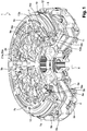
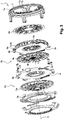
- a dual wear-catching clutch 1 according to one embodiment of the invention is shown in FIGS. Figures 1 to 4 .
- This is intended to couple a motor with a first and a second input shaft of a gearbox (not shown).
- the axis of the double clutch is referenced X.
- the double clutch 1 comprises first and second clutches 2a, 2b (also called clutch mechanisms) for passing reports of different parities.
- the first clutch 2a comprises a first pressure plate 3a and a reaction plate 4 between which a first friction disc 5a extends.
- the first pressure plate 3a is rotatably coupled to the reaction plate 4 and is movable in translation with respect to the latter, between an engaged position and a disengaged position, in which it closes the first friction disc 5a on the reaction plate 4, or respectively releases the first friction disc 5a.
- the reaction plate 4 is fixed on a cover 6 called fixed cover, itself intended to be coupled to the motor shaft.
- the first friction disc 5a is intended to be coupled to the first input shaft of the gearbox.
- the motor shaft is coupled to the first input shaft of the gearbox.
- the first pressure plate 3a is fixed on a cover 7 movable in translation relative to the reaction plate 4 and the fixed cover 6, and extending forwardly.
- First elastic return tongues 8a are mounted between the first pressure plate 3a and the reaction plate 4.
- the first clutch 2a further comprises a first diaphragm 9a in the form of an elastic annular sheet, and is pivotally mounted around bearing zones 10 of the movable cover 7.
- the control of the first clutch 2a is conventionally done by means of a first clutch abutment (not shown) cooperating with the radially inner periphery of the first diaphragm 9a.
- the first diaphragm 9a forms a lever transmitting the force applied by the first control stop to the first pressure plate 3a, via the movable cover 7.
- the first diaphragm 9a In order to allow effective clamping of the first friction disc 3a, the first diaphragm 9a is pre-loaded at rest. Without this pre-charge, the first diaphragm 9a would, at rest, in a state of elasticity requiring a start of travel of the relatively large first control stop to apply an effective clamping force on the first friction disc 3a.
- the first clutch abutment When the first clutch abutment is actuated, it balances the pre-charge of the first diaphragm 9a before starting the tightening of the first disc. friction 3a.
- the pre-charge of the first diaphragm 9a makes it possible to reduce the approach stroke of the first clutch abutment in order to clamp the first friction disk 3a, and to always have a minimum pre-load force, for example on the ball bearing of the first clutch abutment and the ball bearing which supports the double clutch 1. This increases the life of said bearings and limits the vibration of the double clutch 1.
- the first clutch 2a is of the normally open type.
- the rest position of the first diaphragm 9a therefore corresponds to a disengaged state of the first clutch 2a.
- the first diaphragm 9a preferably has a portion of the Belleville washer type for returning the first diaphragm 9a to its rest position.
- the first diaphragm 9a In the rest position of the first diaphragm 9a, that is to say when the first stop does not exert or little effort on the first diaphragm 9a, the first diaphragm 9a therefore does not exert (or little) stress on the first pressure plate 3a.
- the first pressure plate 3a is separated from the reaction plate 4 by means of the elastic tongues 8a, so as to release the first friction disc 5a.
- the second clutch 2b has a second pressure plate 3b, and a second friction disk 5b extending radially between the reaction plate 4 and the second pressure plate 3b.
- the same reaction plate 4 is thus used for the two clutches 2a, 2b, each friction disc 5a, 5b being disposed on the side of one of the two radial bearing surfaces of the reaction plate 4.
- Second elastic tongues of recall 8b are mounted between the second pressure plate 3b and the reaction plate 4.
- the second pressure plate 3b is coupled in rotation to the reaction plate 4 and is movable in translation relative thereto, between an engaged position and a disengaged position, in which it clamps the second friction disk 5b to the reaction plate 4, or releases the second friction disk 5b, respectively.
- the second friction disc 5b is coupled to the second input shaft of the gearbox.
- the motor shaft is coupled to the second input shaft of the gearbox.
- the second clutch 2b further comprises a second diaphragm 9b in the form of an elastic annular sheet whose radially outer periphery is pivotally mounted relative to the fixed cover.
- An elastic member 11 maintains the radially outer periphery of the second diaphragm bearing 12 on the fixed lid 6 ( figure 4 ).
- the control of the second clutch 2b is conventionally done by means of a second clutch abutment (not shown) cooperating with the radially inner periphery of the second diaphragm 9b, via a force transmission member (not shown). ).
- the second diaphragm 9b forms a lever transmitting the force applied by the second clutch abutment to the second pressure plate 3b, to allow effective clamping of the second friction disc 5b.
- the second clutch 2b is also of the normally open type. In the rest position of the second diaphragm 9b, that is to say when the second control stopper exerts little or no effort on the second diaphragm 9b, the second diaphragm 9b does not exert (or little) stress on the second pressure plate 3b.
- the second pressure plate 3b is spaced from the reaction plate 4 via the elastic tongues 8b, so as to release the second friction disk 3b.
- the fixed cover 6 comprises, from the rear to the front, radial flanges 6a for fixing on the reaction plate 4, connected to an annular portion 6b surrounding, at least in part, the second pressure plate 3b, the second friction disc 5b and / or the second diaphragm 9b. Said annular portion 6b is extended by an annular portion 6c extending radially inwards.
- the movable cover 7 has a radially outer portion 7a extending forwardly from the first pressure plate 3a and partially surrounding the fixed cover 6, extended at the front by a radially extending portion 7b. inside and serving to support the first diaphragm 9a.
- the first clutch 2a is equipped with first detection and wear compensating means.
- the first catch and wear detecting means equipping the first clutch 2a are interposed axially between the fixed cover 6 and the first diaphragm 9a, more precisely interposed axially between the radial portion 6c of the fixed cover 6 and the first diaphragm 9a.
- the first means of catching up and detecting wear comprise a first movable retraction member 13a in the form of a ring having an end against which the first diaphragm 9a is able to bear, and an end comprising at least a ramp 14a extending circumferentially, cooperating with an associated counter ramp 15a formed directly on the radial portion 6c of the fixed cover 6 (see FIG. figure 6 for example).
- the counter ramp 15a may be formed by an independent piece and fixed on the fixed cover 6.
- the first catch-up and wear detection means also comprise a first movable detection member 16a in the form of a ring having one end against which the first diaphragm 9a is able to come into abutment, and an end comprising less a ramp 17a extending circumferentially, cooperating with the counter-ramp 15a of the radial portion 6c of the fixed cover 6 (see figure 6 for example).
- the angle of the ramps 14a, 17a of said movable members 13a, 16a and of the counter ramp 15a of the fixed cover 6 is between 2 and 20 °
- the two movable members 13a, 16a are concentric and separated from each other, the first detection member 16a being located radially outside the first wear-compensating member 13a.
- the respective positions of said movable members 13a, 16a can be reversed. Note however that the possibility of inversion of the movable members 13a, 16a is related to the internal architecture of the mechanism.
- Centering means such as for example pads, ensure the proper positioning of the movable members 13a, 16a.
- a first elastic member 18a such as for example a circumferentially extending tension spring, is mounted between the first detection member 16a and the fixed cover 6.
- a second elastic member 19a such as for example a pin-shaped spring, is mounted between the first detection member 16a and the first catch member 13a.
- the length of the first spring 18a is important, so as to be able to solicit the displacement of the first detection member 16a over a wide angular range (for example of the order of 120 °).
- the first clutch 2a also comprises at least one first pressing member 20a ( figure 2 ) is in the form of an elastic tongue exerting an axial force.
- Said tongue 20a is fixed to the fixed cover 6, at a first end, and is able to bear, at a second end, on the first detection member 16a and possibly on the first wear compensating member 13a, so that to constrain them in bearing on the radial part 6c of the fixed cover 6.
- the pressing member 20a exerts a pressure force distributed between the sensing member 16a. and the catch member 13a.
- the axial component of this force along the X axis is applied to an application radius located between the detection member 16a and the catch member 13a.
- An abutment member 21a is fixed on the second end of said tongue 20a.
- the stop member 21a has the general shape of a stud.
- the stop stud 21a has in particular a first end 22a ( figure 4 ) fixed, for example by riveting, radially between the first sensing member 16a and the first wear compensating member 13a, preferably radially midway between said movable members 13a, 16a, and a second cylindrical end 23a forming a enlarged head of larger dimension than the rest of the stud 21a and defining a shoulder.
- the abutment member 21a passes through a hole in the movable cover 7 and is able to bear against a radial bottom surface formed by a recess 24 formed in the movable cover 7.
- the enlarged head 23a of the abutment member 21a is intended to bear against the bottom surface of the counterbore 24 when the displacement of the first pressure plate 3a is important, that is to say when there is a significant wear of the lining of the first friction disc 5a and / or of the counter-materials of the first pressure plate 3a and the reaction plate 4.
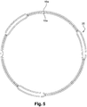
- these may comprise at least one zone 25 in which they are spaced apart. other, as illustrated in figure 5 .
- the movable members 13a, 16a and have, in front view, a generally circular shape with at least one zone 25 provided with bulges in which the movable members 13a, 16a are locally spaced from each other in the radial direction, the second end of the tongue 20a pressing against the corresponding secondary ends of the movable members 13a, 16a at one of the zones 25.
- the first clutch can then comprise three tabs 20a, each equipped with a stop member 21a of structure as described above.
- the three zones 25 are evenly distributed over the entire circumference and are therefore angularly offset by 120 °.
- the first means of catching up and detecting wear are inoperative when the linings of the first friction disk 5a are not or little worn out and the counter-materials of the first pressure plate 3a and the associated reaction plate 4 are not not worn, for example when the cumulative axial wear is less than 0.05 mm.
- FIGS 8 to 11 illustrate the case where the lining of the first friction disc 5a (or the counter-materials of the first pressure plate 3a and the reaction plate 4) have a high wear, which must be made up to avoid a malfunction of the first clutch 2a.
- the head 23a of the abutment member 21a abuts on the bottom surface of the countersink 24 of the movable cover 7, in fully engaged position, so that the second end of the elastic tongue 20a is detached from the secondary end corresponding first detection member 16a.
- a game j1 is formed between said secondary end of the first detection member 16a and the second end of the tongue 20a.
- the first detection member 16a which is then no longer subjected to an axial force, is rotated by the first elastic member 18a, so as to at least partially fill the clearance j1 ( figure 9 ). During this rotation, the second elastic member 19a is constrained.
- the rotation of the first detecting member 16a is stopped when the corresponding secondary end of the first detecting member 16a bears again on the second end of the tongue 20a. It will be noted that during this phase, the first catch member 13a is held in abutment on the fixed cover 6 by the first diaphragm 9a. It is immobilized in rotation relative to the fixed cover 6.
- the first diaphragm 9a transfers its support from the first catch member 13a to the first detection member 16a.
- the Figures 10 and 11 are views illustrating the positions of these elements during such a transfer.
- the first pressure plate 3a is spaced from the reaction plate 4 by means of the corresponding return tongues 8a, so as to release the first friction disk 5a.
- the first diaphragm 9a As illustrated in figure 10 when the first diaphragm 9a is in the fully disengaged position, it completely releases the first catch member 13a. In this position, the first detection member 16a is held fixed in rotation by pressing on the first diaphragm 9a and on the fixed cover 6. Moreover, the head 23a of the stop member 21a is spaced from the bottom surface of the counterbore 24 of the movable cover 7 and the second end of the movable tab 20a is spaced from a game j2 with respect to the corresponding second end of the first catch member 13a.
- the first catch member 13a constrained by the second elastic member 19a, is thus rotated as shown in FIG. figure 11 , so as to fill all or part of the game j2 between said first catch member 13a and the tongue 20a.
- the pivoting of the first catch member 13a and the first sensing member 16a relative to the fixed cover 6 allows, via the ramps 14a, 17a and against the ramp 15a, to increase the axial distance between the fixed cover 6 and the bearing area of the first diaphragm 9a on said members 13a, 16a, which makes it possible to progressively compensate for the wear of the linings of the first friction disc 5a and / or the wear of the counter-materials of the first pressure plate 3a and reaction plate 4.
- Such a structure also makes it possible to maintain the operating angle of the first diaphragm 9a, so as to maintain a constant pre-load force and reduce the mechanical stresses.
- the second clutch 2b is equipped with second means of catching up and detecting wear.
- the second catch-up and wear detection means equipping the second clutch 2b are interposed axially between the second diaphragm 9b and the second pressure plate 3b.
- the second catch-up and wear detection means comprise a second mobile catch-up member 13b in the form of a ring having one end against which the second diaphragm 9b is able to bear, and an end comprising at least a ramp 14b extending circumferentially, cooperating with an associated counterbeam 15b formed directly on the second pressure plate 3b.
- the second catch-up and wear detection means also comprise a second mobile detection member 16b in the form of a ring having one end against which the second diaphragm 9b is able to come into abutment, and a second end comprising at least one ramp 17b extending circumferentially, cooperating with the counter-ramp 15b of the second pressure plate 3b.
- the angle of the ramps 14b, 17b of said movable members 13b, 16b and of the counter-ramp 15b of the second pressure plate 3b is between 2 and 20 °.
- the two movable members 13b, 17b are concentric and separated from each other for example by centering and spacing pins.
- the second mobile detection member 16b is located radially outside the second corresponding mobile retraction member 13b.
- the respective positions of said movable members 13b, 16b can be reversed.
- a first circumferentially extending first tension spring 18b is mounted between the second sensing member 16b and the second pressure plate 3b.
- a second spring such as for example a pin-shaped spring 19b, is mounted between the second detection member 16b and the second catch member 13b.
- the length of the first spring 18b is important, so as to be able to bias the displacement of the second detection member 16b over a wide angular range (for example of the order of 120 °).
- the second clutch 2b also comprises at least one second pressing member 20b in the form of an elastic tongue exerting an axial force.
- Said tongue 20b is fixed to the pressure plate 3b at a first end and bears, at a second end, on the corresponding secondary end of the second detection member 16b and possibly on the second wear compensating member 13b , so as to constrain bearing on the second pressure plate 3b.
- An abutment member 21b is attached to the second end of said tab 20b.
- the abutment member 21b has the general shape of a stud.
- the abutment stud 21b comprises in particular a first end 22b fixed, for example by riveting, radially between the second detection member 16b and the second wear-catching member 13b, preferably radially halfway between said movable members 13b. , 16b, and a second cylindrical end 23b forming an enlarged head of larger dimension than the rest of the stud 21b and defining a shoulder.
- the abutment member 21b passes through a hole in the fixed cover 6 and is able to bear against a radial surface of the fixed cover 6.
- the enlarged head 23b of the abutment member 21b is intended to rest on the corresponding radial surface when the displacement of the second pressure plate 3b is large, that is to say when there is wear. important seals of the second friction disc 5b and / or counter-materials of the second pressure plate 3b and the reaction plate 4.
- the second catch-up and wear-detection means are inoperative when the linings of the second friction disc 5b are not or little worn out and the counter-materials of the second pressure plate 3b and the reaction plate 4 associated with them are not not worn, for example when the cumulative axial wear is less than 0.05 mm.
- the second end of the resilient tongue 20b and / or the second diaphragm 9b maintains the second sensing member 16b and the second catch member 13b resting on the second turntable. pressure 3b, regardless of the operating phase of the second clutch 2b (clutch / clutch).
- the resistive torque generated by the friction between said members 13b, 16b and the second pressure plate 3b is greater than the torque exerted by the springs 18b, 19b.
- Said members 13b, 16b are thus immobilized in rotation relative to the second pressure plate 3b, whatever the operating phase of the second clutch 2b.
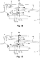
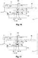
- FIGS 14 to 17 illustrate the case where the linings of the second friction disc 5b (or the counter-materials of the second pressure plate 3b and the reaction plate 4) have a high wear, which must be made up to avoid a malfunction second clutch 2b.
- the second detection member 16b which is then no longer subjected to an axial force, is rotated by the first elastic member 18b, so as to at least partially fill the game I1 ( figure 9 ). During this rotation, the second elastic member 19b is constrained.
- the rotation of the second detection member 16b is stopped when the corresponding secondary end of the second detection member 16b bears again on the second end of the tongue 20b. It will be noted that during this phase, the second catch member 13b is held in abutment on the second pressure plate 3b by the second diaphragm 9b. It is therefore immobilized in rotation relative to the second pressure plate 3b.
- the second diaphragm 9b transfers its support from the second catch member 13b to the second detection member 16a.
- the figures 15 and 16 are views illustrating the positions of these elements during such a transfer.
- the second pressure plate 3b is spaced from the reaction plate 4 via the corresponding return tongues 8b, so as to release the second friction disk 5b.
- the second catch member 13b constrained by the second elastic member 19b, is thus rotated as shown in FIG. figure 17 , so as to fill all or part of the game I2 between said second catch member 13b and the tongue 20b.
- the pivoting of the second catch member 13b and the second detection member 16b with respect to the second pressure plate 3b makes it possible, by means of the ramps 14b, 17b, and against the ramp 15b, to increase the axial distance between the second pressure plate 3b and the bearing zone of the second diaphragm 9b on said members 13b, 16b, which makes it possible to progressively compensate for the wear of the linings of the second friction disc 5b and / or the wear of the counter-materials of the second pressure plate 3b and the reaction plate 4.
- Such a structure also makes it possible to maintain the operating angle of the second diaphragm 9b, so as to maintain a constant pre-load force and reduce the mechanical stresses.
- the return means of the pressure plates 3a, 3b can exert a major effort, this effort being taken by the organ corresponding mobile retraction 13a, 13b then by the corresponding diaphragm 9a, 9b, or by the corresponding mobile detection member 16a, 16b and by the corresponding diaphragm 9a, 9b, depending on the position of said diaphragm 9a, 9b.
- said movable members 13a, 13b, 16a, 16b are not subjected to the force exerted by the return means 8a, 8b of the pressure plate 3a, 3b and it is therefore possible to request easily their displacement using the springs 18a, 18b, 19a, 19b, in case of wear.
- the tabs 20a, 20b forming the pressing members are respectively fixed to the fixed cover 6, and the pressure plate 3b and are therefore not subject to fatigue phenomena due to the clutch cycles and disengagement in operation.
- each abutment member 21a, 21b can be axially supported on the second end of the corresponding resilient tongue 20a, 20b, an attachment of the abutment member 21a, 21b of said resilient tongue 20a, 20b at the end. 22a, 22b not being mandatory.
- the abutment is oriented so that the second end of the tongue 20a, 20b of the corresponding detecting member 16a, 16b can be detached by means of the abutment member 21a, 21b, in case of wear.
- each stop member 21a, 21b is fixed relative to the movable cover 7 or relative to the fixed cover 6, respectively, the second end 22a, 22b of each stop member 21a, 21b being intended for come to bear axially on the second end of the corresponding resilient tongue 20a, 20b.
- the positioning of the first means for detecting and compensating for wear between the first diaphragm 9a and the fixed cover 6, on the one hand, and the positioning of the second detection and wear-compensating means between the second diaphragm 9b and the second second pressure plate 3b makes it possible to simplify the structure of the double clutch 1, to reduce the radial size of the latter and to better control the operation of said means for detecting and compensating for wear in positioning them between parts that are subjected to small deformations in operation. It thus better control the positions of the movable members 13a, 13b, 16a, 16b.
- each stop member 21a, 21b is connected to the second end of the corresponding tongue 20a, 20b, in an area located between the sensing member and the catch member, makes it possible to reduce as much as possible the deformation of this second end, so as to better control the axial positions of the various movable elements 13a, 13b, 16a, 16b, and therefore the resulting wear correction. This avoids or limits any overcompensation or under-compensation of wear.
Description
La présente invention concerne un dispositif d'embrayage à rattrapage d'usure, notamment pour véhicule automobile.The present invention relates to a clutch device to take up wear, especially for a motor vehicle.
Un dispositif d'embrayage comporte classiquement un plateau de réaction, un plateau de pression mobile et un disque de friction monté entre lesdits plateaux de réaction et de pression. Le mouvement du plateau de pression est commandé par un diaphragme, lui-même commandé par une butée d'embrayage.A clutch device conventionally comprises a reaction plate, a movable pressure plate and a friction disk mounted between said reaction and pressure plates. The movement of the pressure plate is controlled by a diaphragm, itself controlled by a clutch abutment.
Le plateau de pression est ainsi mobile entre une position d'embrayage dans laquelle le disque de friction est serré entre lesdits plateaux de pression et de réaction, et une position de débrayage dans laquelle le disque de friction est libéré.The pressure plate is thus movable between a clutch position in which the friction disk is clamped between said pressure and reaction plates, and a disengaging position in which the friction disk is released.
L'utilisation du dispositif d'embrayage provoque une usure des garnitures du disque de friction ainsi que des contre-matériaux des plateaux de pression et de réaction associés. Ceci se traduit par une variation de la position du plateau de pression par rapport au diaphragme associé et/ou par rapport au plateau de réaction, générant une variation de l'effort de serrage du disque de friction et une modification du point de léchage et de la course de la butée d'embrayage. On rappelle que le point de léchage est la position à partir de laquelle un couple peut être transmis au travers du dispositif d'embrayage.The use of the clutch device causes wear of the friction disc liners and the counter-materials of the associated pressure and reaction plates. This results in a variation of the position of the pressure plate relative to the associated diaphragm and / or with respect to the reaction plate, generating a variation of the friction disk clamping force and a modification of the licking point and the stroke of the clutch stop. It is recalled that the licking point is the position from which a torque can be transmitted through the clutch device.
Un dispositif d'embrayage à rattrapage d'usure est connu du document
Des moyens de rattrapage de l'usure du disque de friction sont intercalés entre le diaphragme et le plateau de pression, et comprennent au moins un organe de rattrapage mobile dans une plage déterminée et comportant une rampe coopérant avec une contre-rampe tournée du côté du plateau de pression, de façon à ajuster la distance entre le diaphragme et le plateau de pression et compenser l'usure du disque de friction en fonction de la position angulaire de la rampe par rapport à la contre-rampe.Means for catching the wear of the friction disk are interposed between the diaphragm and the pressure plate, and comprise at least one retrofit member movable in a determined range and having a ramp cooperating with a counter-ramp turned on the side of the diaphragm. pressure plate, so as to adjust the distance between the diaphragm and the pressure plate and compensate the wear of the friction disc according to the angular position of the ramp relative to the counter-ramp.
Le dispositif comporte en outre des moyens de détection de l'usure aptes à autoriser le déplacement de l'organe de rattrapage mobile en cas d'usure du disque de friction et aptes à empêcher un tel déplacement lorsque cette usure n'est pas suffisante, lesdits moyens de détection comportant au moins un organe de détection mobile, dans une plage déterminée, par rapport à l'organe de rattrapage et comportant une rampe coopérant avec une contre-rampe tournée du côté du plateau de pression.The device further comprises wear detecting means adapted to allow the displacement of the movable catch member in case of wear of the friction disc and able to prevent such displacement when this wear is not sufficient, said detection means comprising at least one movable detection member, in a given range, with respect to the catch member and having a ramp cooperating with a counter-ramp turned on the side of the pressure plate.
Le dispositif comporte enfin un organe presseur venant contraindre les rampes desdits organes mobiles contre les contre-rampes associées, l'organe presseur étant apte à coopérer avec une butée fixe, de manière à libérer lesdits organes mobiles lorsqu'une usure du disque de friction est détectée.Finally, the device comprises a pressure member constraining the ramps of said movable members against the associated counter ramps, the pressing member being adapted to cooperate with a fixed stop, so as to release said movable members when a wear of the friction disc is detected.
L'organe de rattrapage mobile est sollicité à l'aide d'un ressort, de façon à rattraper le jeu entre celui-ci et l'organe presseur, lorsque ledit organe de rattrapage mobile est libéré par l'organe presseur et par le diaphragme. Par ailleurs, l'organe de détection mobile est sollicité par un autre ressort de façon à rattraper le jeu entre celui-ci et l'organe presseur, lorsque ledit organe de détection mobile est libéré par l'organe presseur et par le diaphragme.The movable catch member is biased by means of a spring, so as to catch the clearance between the latter and the pressing member, when said movable catch member is released by the pressure member and the diaphragm . Furthermore, the mobile detection member is biased by another spring so as to make up the clearance between the latter and the pressing member, when said movable detection member is released by the pressing member and the diaphragm.
En fonctionnement, l'ensemble est soumis, de façon alternée, à des phases successives d'embrayage et de débrayage.In operation, the assembly is subjected, alternately, to successive phases of clutch and disengagement.
En phase d'embrayage, le diaphragme appuie sur le plateau de pression, par l'intermédiaire de l'organe de rattrapage de jeu. En phase de débrayage, le plateau de pression est rappelé vers sa position de débrayage, par l'intermédiaire de moyens de rappel prenant généralement la forme de languettes élastiquement déformables.In the clutching phase, the diaphragm presses on the pressure plate, via the play-catching member. In the declutching phase, the pressure plate is returned to its disengaged position by means of return means generally taking the form of elastically deformable tongues.
Lorsque le disque de friction n'est pas usé et que les contre-matériaux des plateaux de pression et de réaction ne sont pas usés, l'organe presseur maintient constamment l'organe de détection et l'organe de rattrapage en appui sur le disque de pression : lesdits organes sont immobilisés.When the friction disk is not worn and the counter-materials of the pressure and reaction plates are not worn, the pressing member constantly holds the detection member and the catch member resting on the disk pressure: said organs are immobilized.
En cas d'usure, l'organe presseur vient en appui sur la butée et un jeu se crée entre l'organe presseur et l'organe de détection. Comme ce dernier est contraint par un ressort, il est déplacé de façon à combler le jeu précité. En position embrayée, l'effort appliqué par le diaphragme sur l'organe de rattrapage empêche le déplacement de ce dernier, par appui et frottement sur le plateau de pression. Ensuite, lorsque le diaphragme est déplacé dans sa position débrayée, les languettes de rappel du plateau de pression tendent à plaquer le plateau de pression contre l'organe de rattrapage de jeu, et l'organe de rattrapage de jeu contre le diaphragme. L'effort exercé par les languettes de rappel est relativement faible de façon à autoriser, malgré les frottements en jeu, un déplacement de l'organe de rattrapage de jeu, sous l'effet de la contrainte appliquée par le ressort correspondant. Ce déplacement permet de rattraper le jeu entre l'organe presseur et l'organe de rattrapage. On rattrape ainsi l'usure du plateau de friction ainsi que l'usure des contre-matériaux des plateaux de pression et de réaction associés.In case of wear, the pressure member bears on the stop and a play is created between the pressing member and the detection member. As the latter is constrained by a spring, it is moved to fill the game above. In the engaged position, the force applied by the diaphragm on the catch member prevents the displacement of the latter, by pressing and friction on the pressure plate. Then, when the diaphragm is moved to its disengaged position, the return tongues of the pressure plate tend to press the pressure plate against the play catch member, and the play catch member against the diaphragm. The force exerted by the return tongues is relatively small so as to allow, despite the friction in play, a displacement of the play catch member, under the effect of the stress applied by the corresponding spring. This movement makes it possible to make up the clearance between the pressing member and the catching member. This compensates for the wear of the friction plate as well as the wear of the counter-materials of the associated pressure and reaction plates.
Un tel fonctionnement nécessite notamment l'utilisation de moyens de rappel du plateau de pression exerçant des efforts relativement faibles, pour permettre le déplacement de l'organe de rattrapage malgré les frottements en jeu. Ceci nuit au fonctionnement car de tels moyens de rappel peuvent transmettre des vibrations axiales et générer des phénomènes de pompage du plateau de pression.Such an operation requires in particular the use of biasing means of the pressure plate exerting relatively low forces, to allow the displacement of the catch member despite friction in play. This is detrimental to the operation because such means of recall can transmit axial vibrations and generate pumping phenomena of the pressure plate.
Afin de remédier à cet inconvénient, la demande de brevet
- des moyens de rattrapage de l'usure du disque de friction étant intercalés entre le diaphragme et le plateau de pression, lesdits moyens de rattrapage d'usure comportant au moins un organe de rattrapage mobile dans une plage déterminée et comportant une rampe coopérant avec une contre-rampe tournée du côté du plateau de pression, de façon à ajuster la distance entre le diaphragme et le plateau de pression et compenser l'usure du disque de friction en fonction de la position de la rampe par rapport à la contre-rampe,
- des moyens de détection de l'usure aptes à autoriser le déplacement dudit organe de rattrapage mobile en cas d'usure du disque de friction et aptes à empêcher un tel déplacement lorsque cette usure n'est pas suffisante, lesdits moyens de détection comportant au moins un organe de détection mobile, dans une plage déterminée, par rapport à l'organe de rattrapage mobile et comportant une rampe coopérant avec une contre-rampe tournée du côté du plateau de pression,
- au moins un organe presseur venant contraindre au moins la rampe de l'organe de détection contre la contre-rampe associée, l'organe presseur étant apte à coopérer avec une butée fixe de manière à libérer lesdits organes mobiles lorsqu'une usure du disque de friction est détectée,
- l'organe de rattrapage mobile étant sollicité de façon à se déplacer lorsque ledit organe de rattrapage mobile est libéré par le diaphragme,
- l'organe de détection mobile étant sollicité de façon à se déplacer et rattraper, au moins en partie, le jeu entre celui-ci et l'organe presseur, lorsque ledit organe de détection mobile est libéré par l'organe presseur et par le diaphragme.
- means for compensating for the wear of the friction disk being interposed between the diaphragm and the pressure plate, said wear compensating means comprising at least one movable catch member in a determined range and comprising a ramp co-operating with a counter -turning turned side of the pressure plate, so as to adjust the distance between the diaphragm and the pressure plate and compensate the wear of the friction disc according to the position of the ramp relative to the counter-ramp,
- wear detecting means capable of permitting the displacement of said movable catch member in case of wear of the friction disk and able to prevent such displacement when this wear is not sufficient, said detecting means comprising at least a movable detection member, in a determined range, with respect to the mobile retraction member and having a ramp cooperating with a counter-ramp turned towards the pressure plate,
- at least one pressing member for constraining at least the ramp of the detection member against the associated counter-ramp, the member pressing member adapted to cooperate with a fixed stop so as to release said movable members when wear of the friction disc is detected,
- the mobile catch member being urged to move when said movable catch member is released by the diaphragm,
- the mobile detection member being biased so as to move and catch, at least in part, the clearance between the latter and the pressing member, when said movable detection member is released by the pressing member and by the diaphragm .
De plus, le diaphragme libère l'organe de détection mobile et empêche le déplacement de l'organe de rattrapage mobile, en position totalement embrayée, et le diaphragme libère l'organe de rattrapage mobile et empêche le déplacement de l'organe de détection mobile, en position totalement débrayée, le diaphragme venant toujours en appui sur l'un au moins desdits organes mobiles entre ses positions totalement embrayée et totalement débrayée.In addition, the diaphragm releases the movable detection member and prevents the movement of the mobile retraction member, in fully engaged position, and the diaphragm releases the mobile retraction member and prevents the displacement of the movable detection member. , in fully disengaged position, the diaphragm always bearing on at least one of said movable members between its fully engaged positions and fully disengaged.
De cette manière, les moyens de rappel du plateau de pression peuvent exercer un effort important, cet effort étant repris par l'organe de rattrapage mobile puis par le diaphragme, ou par l'organe de détection mobile puis par le diaphragme, en fonction de la position du diaphragme. En effet, lors de leurs déplacements, lesdits organes mobiles ne sont pas soumis à l'effort exercé par les moyens de rappel du plateau de pression et il est donc possible de solliciter aisément leur déplacement, en cas d'usure.In this way, the biasing means of the pressure plate can exert a major force, this force being taken up by the mobile retraction member and then by the diaphragm, or by the movable detection member and then by the diaphragm, depending on the position of the diaphragm. Indeed, during their movements, said movable members are not subjected to the force exerted by the biasing means of the pressure plate and it is therefore possible to easily solicit their displacement, in case of wear.
Comme indiqué précédemment, le fait de disposer de moyens de rappel du plateau de pression exerçant un effort important, tels par exemple que des languettes ressorts ayant une forte raideur, permet de limiter la transmission des vibrations axiales et d'éviter les phénomènes de pompage du plateau de pression.As indicated above, the fact of having biasing means of the pressure plate exerting a large force, such as for example spring tongues having a high stiffness, allows to limit the transmission of axial vibrations and to avoid the pumping phenomena of the pressure plate.
L'organe de détection mobile et l'organe de rattrapage mobile sont sollicités par des organes élastiques, par exemple des ressorts de traction.The movable detection member and the movable catch member are biased by elastic members, for example traction springs.
En particulier, au moins un premier ressort de traction s'étendant circonférentiellement est monté entre l'organe de détection et le plateau de pression, ou entre l'organe de détection et un couvercle couplé en rotation au plateau de pression. Des seconds ressorts de traction s'étendant circonférentiellement sont montés entre l'organe de détection et l'organe de rattrapage. Ces seconds ressorts assurent la fonction de motorisation de l'organe de rattrapage par rapport à l'organe de détection.In particular, at least one circumferentially extending first tension spring is mounted between the sensing member and the pressure plate, or between the sensing member and a cover rotatably coupled to the pressure plate. Second circumferentially extending traction springs are mounted between the sensing member and the catch member. These second springs provide the motorization function of the catch member with respect to the sensing member.
La demande de brevet
On rappelle qu'un double embrayage permet notamment de coupler alternativement l'arbre du moteur du véhicule avec deux arbres coaxiaux d'entrée d'une boîte de vitesses, qui peut être du type robotisée.It is recalled that a double clutch allows in particular to alternately couple the motor shaft of the vehicle with two coaxial input shafts of a gearbox, which can be of the robotic type.
Ainsi, un double embrayage permet de changer de rapport de vitesses tout en maintenant la transmission d'un couple moteur aux roues du véhicule. En effet, les deux embrayages sont associés respectivement à des rapports de vitesses pairs et impairs. Lors d'un changement de rapport de vitesses, un premier embrayage est débrayé alors que le second embrayage est embrayé, si bien que le couple moteur est transféré progressivement du premier au second embrayage.Thus, a dual clutch allows to change gears while maintaining the transmission of a torque engine to the vehicle wheels. Indeed, the two clutches are respectively associated with even and odd gear ratios. During a gearshift, a first clutch is disengaged while the second clutch is engaged, so that the engine torque is progressively transferred from the first to the second clutch.
Chaque embrayage comprend un mécanisme comportant un diaphragme destiné à coopérer avec un plateau de pression solidaire en rotation du couvercle et de l'arbre du moteur. Chaque diaphragme est déplaçable au moyen d'une butée d'embrayage correspondante, entre une position de repos et une position active. Selon le type d'embrayage, la position active du diaphragme correspond à un couplage ou à un découplage des arbres du moteur et de la boîte de vitesses et la position de repos du diaphragme correspond à un découplage ou un couplage de ces arbres. On parle alors respectivement d'embrayage normalement ouvert et d'embrayage normalement fermé.Each clutch comprises a mechanism comprising a diaphragm for cooperating with a pressure plate integral in rotation with the cover and the motor shaft. Each diaphragm is movable by means of a corresponding clutch abutment, between a rest position and an active position. Depending on the type of clutch, the active position of the diaphragm corresponds to a coupling or decoupling of the shafts of the engine and the gearbox and the rest position of the diaphragm corresponds to a decoupling or a coupling of these shafts. These are respectively a normally open clutch and a normally closed clutch.
Pour des raisons de sécurité, l'un au moins des embrayages est du type normalement ouvert.For safety reasons, at least one of the clutches is of the normally open type.
La butée d'embrayage est commandée par un actionneur piloté par un calculateur électronique afin d'exercer une force prédéterminée sur le diaphragme et de le déplacer sur une distance donnée.The clutch stop is controlled by an actuator controlled by an electronic computer to exert a predetermined force on the diaphragm and move it over a given distance.
Le plateau de pression de chaque embrayage, sollicité par le diaphragme correspondant, est destiné à serrer un disque de friction sur un plateau de réaction correspondant. Un plateau de réaction peut être prévu pour chaque embrayage. En variante, on utilise un seul plateau de réaction commun aux deux embrayages, monté entre les deux disques de friction.The pressure plate of each clutch, biased by the corresponding diaphragm, is intended to clamp a friction disc on a corresponding reaction plate. A reaction plate may be provided for each clutch. Alternatively, a single reaction plate common to both clutches, mounted between the two friction discs, is used.
Chaque disque de friction est lié en rotation à un arbre d'entrée de la boîte de vitesses et chaque plateau de réaction est par exemple solidaire en rotation d'un volant lié à l'arbre moteur. Ainsi, le serrage d'un disque de friction entre les plateaux de pression et de réaction correspondants permet la transmission d'un couple entre l'arbre moteur et l'arbre de la boîte de vitesses associés.Each friction disk is rotatably connected to an input shaft of the gearbox and each reaction plate is for example integral in rotation with a flywheel connected to the motor shaft. Thus, the clamping of a friction disk between the corresponding pressure and reaction plates allows the transmission of a torque between the drive shaft and the associated gearbox shaft.
Comme précédemment, l'utilisation des embrayages provoque une usure des garnitures de friction des disques de friction ainsi que des contre-matériaux des plateaux de pression et de réaction associés. Ceci se traduit par une variation de la position de chaque plateau de pression par rapport au diaphragme associé et/ou au plateau de réaction, générant une variation de l'effort de serrage du disque de friction et une modification du point de léchage et de la course à la butée d'embrayage. Dans ce cas, le point de léchage est la position à partir de laquelle une partie du couple du moteur est transmis à l'arbre de la boîte de vitesses lors de la fermeture de l'embrayage.As before, the use of the clutches causes wear of the friction linings of the friction discs as well as the counter-materials of the pressure and associated reaction plates. This results in a variation of the position of each pressure plate with respect to the associated diaphragm and / or the reaction plate, generating a variation of the friction disk clamping force and a modification of the licking point and the stroke at the clutch stop. In this case, the licking point is the position from which a portion of the engine torque is transmitted to the gearbox shaft when closing the clutch.
De manière générale, une telle usure est plus présente au niveau du disque de friction et des plateaux de pression et de réaction appartenant au premier embrayage, c'est-à-dire à l'embrayage associé aux rapports de vitesses impairs. Ainsi, lorsque le double embrayage ne comporte qu'un seul mécanisme de rattrapage d'usure selon l'invention, celui-ci forme de préférence une partie du premier embrayage. Bien entendu, le double embrayage selon l'invention peut comporter à la fois des mécanismes de rattrapage d'usure équipant le premier embrayage et un mécanisme équipant le second embrayage.In general, such wear is more present at the friction disc and the pressure and reaction plates belonging to the first clutch, that is to say the clutch associated with odd speeds reports. Thus, when the double clutch has only one wear-catching mechanism according to the invention, it preferably forms part of the first clutch. Of course, the double clutch according to the invention may comprise both wear compensating mechanisms equipping the first clutch and a mechanism equipping the second clutch.
La demande de brevet
Dans cette demande de brevet est décrit un double embrayage comportant un plateau de réaction destiné à être couplé en rotation à un arbre menant, un premier et un second disque de friction, destinés à être couplés respectivement à un premier et un second arbres menés, un premier et un second plateau de pression, actionnés respectivement par un premier et un second diaphragme de façon à serrer ou libérer le premier et le second disque de friction sur le plateau de réaction, le premier plateau de pression étant relié fixement à un couvercle mobile en translation par rapport au plateau de réaction, et étant actionné par appui du premier diaphragme sur le couvercle mobile, des premiers moyens de détection et de rattrapage de l'usure du premier disque de friction étant intercalés entre le premier diaphragme et le couvercle mobile, des seconds moyens de détection et de rattrapage de l'usure du second disque de friction, étant intercalés entre le second diaphragme et le second plateau de pressionIn this patent application is described a double clutch comprising a reaction plate intended to be coupled in rotation to a driving shaft, a first and a second friction disk, intended to be coupled respectively to a first and a second driven shaft, a first and second pressure plates, respectively actuated by a first and a second diaphragm so as to clamp or release the first and second friction disc on the reaction plate, the first pressure plate being fixedly connected to a movable cover; translation with respect to the reaction plate, and being actuated by pressing the first diaphragm on the movable cover, first detection means and catch-up of the wear of the first friction disc being interposed between the first diaphragm and the movable cover, second means for detecting and catching the wear of the second friction disc, being interposed between the second diaphragm me and the second pressure plate
En fonctionnement, le couvercle mobile est soumis à des contraintes mécaniques importantes pouvant générer des déformées rendant difficile le bon positionnement des éléments constitutifs des premiers moyens de détection et de rattrapage d'usure. Ceci peut affecter de manière sensible le bon fonctionnement des premiers moyens de détection et de rattrapage d'usure.In operation, the movable lid is subjected to significant mechanical stresses that can generate deformities making it difficult to properly position the constituent elements of the first detection and wear-compensating means. This can appreciably affect the proper functioning of the first means of detecting and compensating for wear.
L'invention propose un dispositif d'embrayage à rattrapage d'usure visant à garantir la bonne position des organes de détection et de rattrapage d'usure afin d'éviter toute surcompensation ou sous-compensation de l'usure.The invention proposes a wear-catching clutch device intended to guarantee the correct position of the detection and wear-compensating members in order to avoid any over-compensation or under-compensation of the wear.
A cet effet, elle propose un dispositif d'embrayage à rattrapage d'usure, notamment pour véhicule automobile, comportant :
- un plateau de réaction destiné à être couplé en rotation à un arbre menant, autour d'un axe de rotation,
- un disque de friction portant des garnitures de friction, destiné à être couplé à un arbre mené,
- un plateau de pression actionné par un diaphragme de façon à serrer ou libérer le disque de friction sur le plateau de réaction,
- des moyens de détection et de rattrapage d'usure, aptes à rattraper l'usure du disque de friction, les moyens de détection et de rattrapage d'usure étant intercalés entre une partie fixe par rapport au plateau de réaction, par exemple un couvercle, et le plateau de pression, lesdits moyens de détection et de rattrapage d'usure comportant :
- des moyens de rattrapage d'usure intercalés entre le diaphragme et ladite partie fixe ou entre le diaphragme et le plateau de pression, lesdits moyens de rattrapage d'usure comportant au moins un organe de rattrapage mobile dans une plage déterminée et comportant une rampe coopérant avec une contre-rampe tournée du côté de la partie fixe ou du plateau de pression, de façon à ajuster la distance entre le diaphragme et la partie fixe, ou respectivement entre le diaphragme et le plateau de pression et compenser l'usure correspondante en fonction de la position de la rampe par rapport à la contre-rampe,
- des moyens de détection de l'usure aptes à autoriser le déplacement dudit organe de rattrapage mobile en cas d'usure et aptes à empêcher un tel déplacement lorsque cette usure n'est pas suffisante, lesdits moyens de détection comportant au moins un organe de détection mobile, dans une plage déterminée, par rapport à l'organe de rattrapage mobile et comportant une rampe coopérant avec une contre-rampe tournée du côté de la partie fixe ou du plateau de pression,
- au moins un organe presseur venant contraindre au moins la rampe de l'organe de détection contre la contre-rampe associée, l'organe presseur étant apte à coopérer avec une butée fixe de manière à libérer l'organe de détection lorsqu'une usure est détectée,
- l'organe de rattrapage mobile étant sollicité de façon à se déplacer lorsque ledit organe de rattrapage mobile est libéré par le diaphragme,
- l'organe de détection mobile étant sollicité de façon à se déplacer et à rattraper, au moins en partie, le jeu entre celui-ci et l'organe presseur, lorsque ledit organe de détection mobile est libéré par l'organe presseur et par le diaphragme,
- caractérisé en ce qu'il comporte un organe de butée relié à l'organe presseur, l'organe de butée étant conçu pour écarter l'organe presseur de l'organe de détection et/ou de l'organe de rattrapage en cas d'usure, l'organe de butée étant relié à l'organe presseur dans une zone située radialement entre l'organe de détection et de l'organe de rattrapage.
- a reaction plate adapted to be coupled in rotation to a driving shaft, about an axis of rotation,
- a friction disc carrying friction linings, for coupling to a driven shaft,
- a pressure plate actuated by a diaphragm so as to clamp or release the friction disc on the reaction plate,
- means for detecting and compensating for wear, able to compensate for the wear of the friction disk, the means for detecting and compensating for wear being interposed between a fixed part with respect to the reaction plate, for example a cover, and the pressure plate, said wear detection and correction means comprising:
- wear catching means interposed between the diaphragm and said fixed part or between the diaphragm and the pressure plate, said wear compensating means comprising at least one movable catch member in a determined range and comprising a ramp cooperating with a counter-ramp turned towards the fixed part or the pressure plate, so as to adjust the distance between the diaphragm and the fixed part, or respectively between the diaphragm and the pressure plate and compensate the corresponding wear as a function of the position of the ramp with respect to the counter-ramp,
- wear detecting means capable of permitting the displacement of said movable compensating member in case of wear and capable of preventing such displacement when this wear is not sufficient, said detecting means comprising at least one detection member mobile, in a given range, relative to the movable catch member and having a ramp cooperating with a counter-ramp turned towards the fixed part or the pressure plate,
- at least one pressing member for constraining at least the ramp of the detection member against the associated counter-ramp, the member pressing member adapted to cooperate with a fixed stop so as to release the detection member when wear is detected,
- the mobile catch member being urged to move when said movable catch member is released by the diaphragm,
- the mobile detection member being biased so as to move and to catch, at least in part, the clearance between the latter and the pressing member, when said movable detection member is released by the pressing member and by the diaphragm,
- characterized in that it comprises a stop member connected to the pressure member, the stop member being designed to move the pressing member away from the detection member and / or the catch member in case of wear, the stop member being connected to the pressing member in an area located radially between the sensing member and the catch member.
L'organe de butée étant relié à l'organe presseur dans une zone située entre l'organe de détection et de l'organe de rattrapage, on limite l'effet de basculement de l'organe presseur, un tel basculement ayant une influence sur les positions des zones d'appui réelles de l'organe presseur sur l'organe de détection et/ou sur l'organe de rattrapage. La caractéristique précitée permet ainsi de maîtriser la position desdits organes mobiles, de façon à garantir le bon fonctionnement des moyens de détection et de rattrapage d'usure correspondants et éviter une surcompensation ou une sous-compensation de l'usure.The abutment member being connected to the pressing member in an area between the sensing member and the catching member, limits the tilting effect of the pressure member, such a tilting having an influence on the positions of the actual bearing areas of the pressing member on the sensing member and / or the catch member. The aforementioned characteristic thus makes it possible to control the position of said movable members, so as to guarantee the proper functioning of the corresponding wear detecting and compensating means and to avoid overcompensation or under-compensation of wear.
L'organe de butée peut être relié à l'organe presseur dans une zone située radialement à mi-distance entre l'organe de détection et de l'organe de rattrapage.The stop member may be connected to the pressure member in an area located radially midway between the sensing member and the catch member.
L'organe presseur peut exercer un effort presseur réparti entre l'organe de détection et l'organe de rattrapage et la composante axiale de cet effort suivant l'axe X peut être appliquée sur un rayon d'application situé entre l'organe de détection et l'organe de rattrapage.The pressing member may exert a pressure force distributed between the sensing member and the catch member and the axial component of this force along the axis X may be applied to an application radius located between the sensing member and the catch-up member.
L'organe de rattrapage mobile et l'organe de détection mobile peuvent être concentriques.The movable catch member and the movable detection member may be concentric.
Par ailleurs, l'organe de butée peut comporter une extrémité reliée à une partie fixe ou mobile du dispositif d'embrayage, et une extrémité reliée à l'organe presseur.Furthermore, the stop member may comprise an end connected to a fixed or movable part of the clutch device, and an end connected to the pressing member.
L'organe de détection et l'organe de rattrapage, de forme générale circulaire, peuvent comprendre au moins une zone pourvue de renflements dans laquelle lesdits organes mobiles sont localement écartés l'un de l'autre dans la direction radiale, l'organe presseur venant appuyer sur les extrémités correspondantes des organes mobiles au niveau de ladite zone pourvue de renflements.The detection member and the catch member, of generally circular shape, may comprise at least one zone provided with bulges in which said movable members are locally spaced apart from one another in the radial direction, the pressing member pressing the corresponding ends of the movable members at said area provided with bulges.
L'extrémité de l'organe de butée qui est reliée à l'organe presseur peut être logée dans ladite zone pourvue de renflements.The end of the abutment member which is connected to the pressure member may be accommodated in said area provided with bulges.
L'organe presseur peut comporter au moins une languette élastique dont une extrémité est apte à venir en appui sur l'organe de détection mobile ou sur l'organe de rattrapage mobile correspondant.The pressing member may comprise at least one resilient tongue whose one end is adapted to bear on the movable detection member or on the corresponding mobile retraction member.
L'invention concerne également un double embrayage à rattrapage d'usure, notamment pour véhicule automobile, caractérisé en ce qu'il comporte au moins un dispositif d'embrayage du type précité, le double embrayage comportant :
- au moins un plateau de réaction destiné à être couplé en rotation à un arbre menant,
- un premier et un second disques de friction portant des garnitures de friction, destinés à être couplés respectivement à un premier et un second arbre mené,
- un premier et un second plateau de pression actionnés respectivement par un premier et un second diaphragme de façon à serrer ou libérer le premier et le second disque de friction sur le plateau de réaction, le premier plateau de pression étant relié fixement à un couvercle mobile en translation par rapport au plateau de réaction, et étant actionné par appui du premier diaphragme sur le couvercle mobile,
- un couvercle fixe, fixé au plateau de réaction et logeant le second plateau de pression, le second disque de friction et/ou le second diaphragme,
- des premiers moyens de détection et de rattrapage d'usure, aptes à rattraper l'usure du premier disque de friction, les premiers moyens de détection et de rattrapage d'usure étant montés entre le premier diaphragme et le couvercle fixe,
- des seconds moyens de détection et de rattrapage d'usure, aptes à rattraper l'usure du second disque de friction, les seconds moyens de détection et de rattrapage d'usure étant montés entre le second diaphragme et le second plateau de pression,
- des moyens de rattrapage d'usure intercalés entre le premier diaphragme et le couvercle fixe, ou respectivement entre le second diaphragme et le second plateau de pression, lesdits moyens de rattrapage d'usure comportant au moins un organe de rattrapage mobile dans une plage déterminée et comportant une rampe coopérant avec une contre-rampe tournée du côté du couvercle fixe ou du second plateau de pression, de façon à ajuster la distance entre le premier diaphragme et le couvercle fixe, ou respectivement entre le second diaphragme et le second plateau de pression et compenser l'usure correspondante en fonction de la position de la rampe par rapport à la contre-rampe,
- des moyens de détection de l'usure aptes à autoriser le déplacement dudit organe de rattrapage mobile en cas d'usure et aptes à empêcher un tel déplacement lorsque cette usure n'est pas suffisante, lesdits moyens de détection comportant au moins un organe de détection mobile, dans une plage déterminée, par rapport à l'organe de rattrapage mobile et comportant une rampe coopérant avec une contre-rampe tournée du côté du couvercle fixe ou du second plateau de pression,
- au moins un organe presseur venant contraindre au moins la rampe de l'organe de détection contre la contre-rampe associée, l'organe presseur étant apte à coopérer avec une butée fixe de manière à libérer l'organe de détection lorsqu'une usure est détectée,
- l'organe de rattrapage mobile étant sollicité de façon à se déplacer lorsque ledit organe de rattrapage mobile est libéré par le premier diaphragme ou par le second diaphragme,
- l'organe de détection mobile étant sollicité de façon à se déplacer et à rattraper, au moins en partie, le jeu entre celui-ci et l'organe presseur, lorsque ledit organe de détection mobile est libéré par l'organe presseur et par le premier diaphragme ou second diaphragme,
- un organe de butée étant relié à l'un au moins des organes presseurs, l'organe de butée étant conçu pour écarter l'organe presseur de l'organe de détection et/ou de l'organe de rattrapage en cas d'usure, l'organe de butée étant relié à l'organe presseur dans une zone située entre l'organe de détection et de l'organe de rattrapage, de préférence à mi-distance entre l'organe de détection et de l'organe de rattrapage.
- at least one reaction plate intended to be coupled in rotation to a driving shaft,
- first and second friction discs having friction liners for coupling respectively to a first and a second driven shaft,
- a first and a second pressure plate respectively actuated by a first and a second diaphragm so as to clamp or release the first and second friction disc on the reaction plate, the first pressure plate being fixedly connected to a movable cover; translation with respect to the reaction plate, and being actuated by pressing the first diaphragm on the movable lid,
- a fixed cover, attached to the reaction plate and housing the second pressure plate, the second friction disk and / or the second diaphragm,
- first wear detecting and compensating means adapted to compensate for the wear of the first friction disk, the first detection and wear compensating means being mounted between the first diaphragm and the fixed cover,
- second wear detecting and compensating means adapted to compensate for the wear of the second friction disc, the second wear detecting and compensating means being mounted between the second diaphragm and the second pressure plate,
- wear compensating means interposed between the first diaphragm and the fixed cover, or respectively between the second diaphragm and the second pressure plate, said wear compensating means comprising at least one movable catch member in a determined range and having a ramp cooperating with a counter ramp turned on the side of the fixed cover or the second pressure plate, so as to adjust the distance between the first diaphragm and the fixed cover, or respectively between the second diaphragm and the second pressure plate and compensate for the corresponding wear as a function of the position of the ramp relative to the counter-ramp,
- wear detecting means capable of permitting the displacement of said movable compensating member in case of wear and capable of preventing such displacement when this wear is not sufficient, said detecting means comprising at least one detection member mobile, in a determined range, with respect to the movable catch member and having a ramp cooperating with a counter-ramp turned towards the fixed lid or the second pressure plate,
- at least one pressing member forcing at least the ramp of the detection member against the associated counter ramp, the pressing member being adapted to cooperate with a fixed stop so as to release the detection member when wear is detected,
- the mobile retraction member being urged so as to move when said movable retraction member is released by the first diaphragm or by the second diaphragm,
- the mobile detection member being biased so as to move and to catch, at least in part, the clearance between the latter and the pressing member, when said movable detection member is released by the pressing member and by the first diaphragm or second diaphragm,
- a stop member being connected to at least one of the pressing members, the stop member being designed to move the pressing member away from the detection member and / or the catch member in the event of wear, the stop member being connected to the pressing member in an area between the sensing member and the catch member, preferably midway between the sensing member and the catch member.
Chaque embrayage est ainsi équipé de moyens de rattrapage d'usure présentant un encombrant axial et radial réduit. L'encombrement du double embrayage est donc réduit de manière sensible.Each clutch is thus equipped with wear compensating means having a reduced axial and radial bulge. The size of the double clutch is therefore significantly reduced.
Par ailleurs, le positionnement des premiers et seconds moyens de détection et de rattrapage d'usure, en particulier entre des éléments présentant des déformées peu importantes, permet de mieux contrôler le positionnement des moyens de détection d'usure et des moyens de rattrapage d'usure correspondants. Ceci permet de garantir le bon fonctionnement desdits moyens de détection et de rattrapage d'usure.Moreover, the positioning of the first and second wear detection and compensating means, in particular between elements having small deformations, makes it possible to better control the positioning of the wear detection means and the catch-up means of the wear detection means. corresponding wear. This makes it possible to guarantee the correct operation of said means of detecting and compensating for wear.
Le premier diaphragme ou le second diaphragme peut libérer l'organe de détection mobile et empêcher le déplacement de l'organe de rattrapage mobile, en position totalement embrayée, le premier diaphragme ou second diaphragme pouvant libérer l'organe de rattrapage mobile et empêcher le déplacement de l'organe de détection mobile, en position totalement débrayée, le premier diaphragme ou le second diaphragme venant toujours en appui sur l'un au moins desdits organes mobiles entre ses positions totalement embrayée et totalement débrayée.The first diaphragm or the second diaphragm may release the movable detection member and prevent the mobile retraction member from moving in a fully engaged position, the first diaphragm or second diaphragm being able to release the movable retractor and prevent displacement. of the mobile detection element, in position completely disengaged, the first diaphragm or the second diaphragm always bearing on at least one of said movable members between its fully engaged positions and fully disengaged.
Chaque organe de détection mobile peut se présenter sous la forme d'un anneau comportant une extrémité apte à servir à l'appui du diaphragme correspondant et une extrémité comprenant au moins une rampe s'étendant circonférentiellement, coopérant avec la contre-rampe associée du côté du couvercle fixe ou du second plateau de pression.Each movable detection member may be in the form of a ring having an end adapted to serve to support the corresponding diaphragm and an end comprising at least one ramp extending circumferentially, cooperating with the associated counter ramp on the side fixed cover or second pressure plate.
Le déplacement de la rampe de l'organe de détection mobile par rapport à la contre-rampe associée peut ainsi être obtenu par pivotement de l'organe de détection mobile.The movement of the ramp of the movable detection member with respect to the associated counter ramp can thus be obtained by pivoting of the movable detection member.
En outre, chaque organe de rattrapage mobile peut se présenter sous la forme d'un anneau comportant une extrémité apte à servir à l'appui du diaphragme correspondant et une extrémité comportant au moins une rampe s'étendant circonférentiellement, coopérant avec la contre-rampe associée tournée du côté du couvercle fixe ou du second plateau de pression.In addition, each mobile catch member may be in the form of a ring having an end adapted to serve to support the corresponding diaphragm and an end having at least one ramp extending circumferentially, cooperating with the counter-ramp associated turned on the side of the fixed cover or the second pressure plate.
Le déplacement de la rampe de l'organe de rattrapage mobile par rapport à la contre-rampe associée peut ainsi être obtenu par pivotement de l'organe de rattrapage mobile.The movement of the ramp of the mobile catch member with respect to the associated counter ramp can thus be obtained by pivoting the movable catch member.
L'organe de butée peut comporter une extrémité reliée au couvercle fixe ou au couvercle mobile, et une extrémité reliée à l'organe presseur.The stop member may comprise an end connected to the fixed cover or the movable cover, and an end connected to the pressing member.
Selon une forme de réalisation, l'organe de butée peut comporter une extrémité apte à venir en appui sur le couvercle mobile ou sur le couvercle fixe en cas d'usure, et une extrémité fixée ou venant en appui sur l'organe presseur.According to one embodiment, the abutment member may comprise an end adapted to bear on the movable cover or on the fixed cover in case of wear, and an end fixed or bearing on the pressing member.
Selon une autre forme de réalisation, l'organe de butée peut comporter une extrémité fixée au couvercle mobile ou au couvercle fixe en cas d'usure, et une extrémité venant en appui sur l'organe presseur.According to another embodiment, the stop member may comprise an end attached to the movable cover or the fixed cover in case of wear, and an end bearing against the pressing member.
Le double embrayage ou le dispositif d'embrayage selon l'invention peut également comporter l'une ou plusieurs des caractéristiques suivantes :
- le premier plateau de pression est rappelé vers sa position débrayée, à l'opposé du plateau de réaction, par des premiers moyens de rappel élastique, tels par exemple que des premières languettes élastiques de rappel montées entre le premier plateau de pression et le plateau de réaction,
- le second plateau de pression est rappelé vers sa position débrayée, à l'opposé du plateau de réaction, par des seconds moyens de rappel élastique, tels par exemple que des secondes languettes élastiques de rappel montées entre le second plateau de pression et le plateau de réaction,
- lesdites languettes élastiques assurent le couplage en rotation du plateau de réaction avec les plateaux de pression,
- le premier embrayage est du type normalement ouvert,
- le second embrayage est du type normalement ouvert,
- le double embrayage comporte un seul plateau de réaction servant à l'appui du premier disque de friction et du second disque de friction,
- le premier diaphragme se présente sous la forme d'une tôle annulaire élastique et est monté basculant autour de zones d'appui du couvercle mobile,
- le second diaphragme se présente sous la forme d'une tôle annulaire élastique dont la périphérie radialement externe est montée basculante par rapport au couvercle fixe,
- un organe élastique maintient la périphérie radialement externe du second diaphragme en appui sur le couvercle fixe,
- le couvercle fixe comporte des brides radiales servant à la fixation sur le plateau de réaction, raccordées à une partie annulaire entourant, au moins en partie, le second plateau de pression, le second disque de friction et/ou le second diaphragme, ladite partie annulaire du couvercle fixe étant prolongée par une partie annulaire s'étendant radialement vers l'intérieur,
- la contre-rampe est ménagée sur la partie radiale du couvercle fixe
- le couvercle mobile comporte une partie radialement externe s'étendant depuis le premier plateau de pression et entourant en partie le couvercle fixe, prolongée par une partie s'étendant radialement vers l'intérieur et servant à l'appui du premier diaphragme,
- l'angle des rampes desdits organes mobiles et de la contre-rampe associée est compris entre 2 et 20°.
- l'organe de détection est situé radialement à l'extérieur de l'organe de rattrapage d'usure correspondant,
- un premier organe élastique, tel par exemple qu'un ressort de traction s'étendant circonférentiellement, est monté entre l'organe de détection, d'une part et le couvercle fixe ou le second plateau de pression, d'autre part
- un second organe élastique, tel par exemple qu'un ressort en forme d'épingle, est monté entre chaque organe de détection et l'organe de rattrapage correspondant,
- le premier organe élastique exerce un effort tangentiel ou circonférentiel supérieur à l'effort tangentiel ou circonférentiel exercé par le second organe élastique,
- la longueur du premier organe élastique est importante, de façon à pouvoir solliciter le déplacement de l'organe de détection sur une grande plage angulaire, par exemple de l'ordre de 120°,
- chaque organe presseur se présente sous la forme d'une languette élastique exerçant un effort axial,
- l'organe presseur est fixé au couvercle fixe à une première extrémité, et est apte à venir en appui, à une seconde extrémité, sur l'organe de détection et sur l'organe de rattrapage d'usure correspondants, par exemple sur les premiers organes de détection et de rattrapage mobiles, de façon à contraindre les rampes en appui sur la contre-rampe,
- l'organe presseur est fixé au plateau de pression à une première extrémité, et est apte à venir en appui, à une seconde extrémité, sur l'organe de détection et sur l'organe de rattrapage d'usure correspondants, par exemple sur les seconds organes de détection et de rattrapage mobiles, de façon à contraindre les rampes en appui sur la contre-rampe,
- l'organe presseur peut interagir avec le couvercle fixe ou le couvercle mobile par l'intermédiaire d'une pièce additionnelle.
- un organe de butée est fixé sur la seconde extrémité de ladite languette élastique,
- l'organe de butée comporte une première extrémité fixée, par exemple par rivetage, radialement entre l'organe de détection et l'organe de rattrapage d'usure correspondant, de préférence radialement à mi-distance entre lesdits organes mobiles, et une seconde extrémité cylindrique formant une tête élargie de plus grande dimension que le reste de l'organe de butée et définissant un épaulement,
- la tête élargie de l'organe de butée est apte à venir en appui sur une surface radiale du couvercle mobile ou du couvercle fixe,
- la tête élargie de l'organe de butée est destinée à venir en appui sur la surface radiale correspondante lorsque le déplacement du plateau de pression correspondant est important, c'est-à-dire lorsqu'il existe une usure importante des garnitures du disque de friction et/ou des contre-matériaux du plateau de pression et du plateau de réaction associés.
- l'organe de détection et l'organe de rattrapage comportent au moins une zone dans laquelle ils sont écartés radialement l'un de l'autre,
- l'organe de détection et l'organe de rattrapage ont, en vue de face, une forme générale circulaire avec au moins une zone pourvue de renflements dans laquelle lesdits organes sont localement écartés l'un de l'autre dans la direction radiale, l'organe presseur venant appuyer sur les extrémités correspondantes des organes mobiles au niveau de ladite zone,
- au moins un organe de butée peut traverser axialement le premier diaphragme ou le second diaphragme,
- au moins un organe de butée peut traverser axialement le premier diaphragme et le couvercle mobile,
- au moins un organe de butée peut traverser axialement le second diaphragme et le couvercle fixe,
- l'organe de butée peut présenter un degré de liberté par rapport au couvercle mobile ou par rapport au couvercle fixe, suivant l'axe du double embrayage,
- l'organe de rattrapage mobile et l'organe de détection des premiers moyens de détection et de rattrapage d'usure peuvent être situés radialement à l'extérieur ou radialement à l'intérieur de l'organe de rattrapage mobile et de l'organe de détection des seconds moyens de détection et de rattrapage d'usure, de façon à réduire l'encombrement axial. L'organe de rattrapage mobile et l'organe de détection des premiers moyens de détection et de rattrapage d'usure.
- the first pressure plate is returned to its disengaged position, opposite the reaction plate, by first elastic return means, such as for example that first elastic return tongues mounted between the first pressure plate and the plate of reaction,
- the second pressure plate is returned to its disengaged position, opposite the reaction plate, by second elastic return means, such as for example that second elastic return tongues mounted between the second pressure plate and the plate of reaction,
- said resilient tongues provide rotational coupling of the reaction plate with the pressure plates,
- the first clutch is of the normally open type,
- the second clutch is of the normally open type,
- the double clutch comprises a single reaction plate serving to support the first friction disc and the second friction disc,
- the first diaphragm is in the form of an elastic annular sheet and is pivotally mounted around support zones of the movable cover,
- the second diaphragm is in the form of an elastic annular sheet whose radially outer periphery is pivotally mounted relative to the fixed cover,
- an elastic member keeps the radially outer periphery of the second diaphragm resting on the fixed cover,
- the fixed cover has radial flanges for attachment to the reaction plate, connected to an annular portion surrounding, at least in part, the second pressure plate, the second friction disc and / or the second diaphragm, said annular portion of the fixed cover being extended by an annular portion extending radially inwards,
- the counter-ramp is formed on the radial part of the fixed cover
- the movable lid has a radially outer portion extending from the first pressure plate and partially surrounding the fixed lid, extended by a portion extending radially inwardly and serving to support the first diaphragm,
- the angle of the ramps of said movable members and the associated counter ramp is between 2 and 20 °.
- the detection member is located radially outside the corresponding wear compensating member,
- a first elastic member, such as for example a circumferentially extending tension spring, is mounted between the detection member on the one hand and the fixed cover or the second pressure plate on the other hand;
- a second elastic member, such as for example a pin-shaped spring, is mounted between each detection member and the corresponding catch member,
- the first elastic member exerts a tangential or circumferential force greater than the tangential or circumferential force exerted by the second elastic member,
- the length of the first elastic member is important, so as to be able to urge the displacement of the detection member over a wide angular range, for example of the order of 120 °,
- each pressing member is in the form of an elastic tongue exerting an axial force,
- the pressure member is fixed to the fixed cover at a first end, and is able to bear, at a second end, on the detection member and on the corresponding wear compensating member, for example on the first movable detection and retraction members, so as to constrain the ramps against the counter ramp,
- the pressure member is fixed to the pressure plate at a first end, and is able to bear, at a second end, on the detection member and the corresponding wear compensating member, for example on the second movable detecting and catching members, so as to constrain the ramps against the counter ramp,
- the pressing member may interact with the fixed cover or the movable cover via an additional piece.
- an abutment member is fixed on the second end of said elastic tongue,
- the abutment member comprises a first end fixed, for example by riveting, radially between the sensing member and the corresponding wear compensating member, preferably radially at mid-distance between said movable members, and a second end cylindrical forming an enlarged head of larger dimension than the rest of the stop member and defining a shoulder,
- the enlarged head of the abutment member is adapted to bear against a radial surface of the movable cover or the fixed cover,
- the enlarged head of the abutment member is intended to rest on the corresponding radial surface when the displacement of the corresponding pressure plate is large, that is to say when there is a significant wear of the disc seals. friction and / or counter-materials of the pressure plate and the associated reaction plate.
- the detection member and the catch member comprise at least one zone in which they are radially spaced apart from one another,
- the sensing element and the catching member have, in front view, a generally circular shape with at least one zone provided with bulges in which said members are locally spaced apart. the other in the radial direction, the pressing member pressing on the corresponding ends of the movable members at said zone,
- at least one stop member can axially pass through the first diaphragm or the second diaphragm,
- at least one stop member can axially pass through the first diaphragm and the movable cover,
- at least one stop member can axially pass through the second diaphragm and the fixed cover,
- the stop member may have a degree of freedom with respect to the movable cover or relative to the fixed cover, along the axis of the double clutch,
- the mobile retraction member and the detection member of the first wear detecting and compensating means may be located radially on the outside or radially inside the movable retraction member and the detent member. detection of the second means of detecting and compensating for wear, so as to reduce the axial size. The mobile catch-up member and the detection member of the first detection and wear-catching means.
L'invention sera mieux comprise et d'autres détails, caractéristiques et avantages de l'invention apparaîtront à la lecture de la description suivante faite à titre d'exemple non limitatif en référence aux dessins annexés dans lesquels :
- la
figure 1 est une vue en perspective avec écorché partiel, d'un double embrayage selon une forme de réalisation de l'invention, - les
figures 2 et3 sont des vues éclatées, en perspective, du double embrayage, - la
figure 4 est une vue en coupe axiale du dispositif d'embrayage, - la
figure 5 est une vue de face de l'organe de détection et de l'organe de rattrapage équipant le premier embrayage ou équipant le second embrayage, - les
figures 6 sont des vues schématiques illustrant le fonctionnement du premier embrayage, en l'absence d'usure,et 7 - les
figures 8 à 11 sont des vues schématiques illustrant le fonctionnement du premier embrayage, en cas d'usure, - les
figures 12 et 13 sont des vues schématiques illustrant le fonctionnement du second embrayage, en l'absence d'usure, - les
figures 14 à 17 sont des vues schématiques illustrant le fonctionnement du second embrayage, en cas d'usure, - la
figure 18 est une vue schématique illustrant les moyens de détection et de rattrapage d'usure du premier embrayage, selon une autre forme de réalisation de l'invention, - la
figure 19 est une vue schématique illustrant les moyens de détection et de rattrapage d'usure du second embrayage, selon une autre forme de réalisation de l'invention, - la
figure 20 est une vue schématique illustrant les moyens de détection et de rattrapage d'usure du premier embrayage, selon encore une autre forme de réalisation de l'invention, - la
figure 21 est une vue schématique illustrant les moyens de détection et de rattrapage d'usure du second embrayage, selon encore une autre forme de réalisation de l'invention.
- the
figure 1 is a perspective view with partial cutaway, of a double clutch according to one embodiment of the invention, - the
figures 2 and3 are exploded views, in perspective, of the double clutch, - the
figure 4 is an axial sectional view of the clutch device, - the
figure 5 is a front view of the detection member and the retrofitting member equipping the first clutch or equipping the second clutch, - the
Figures 6 and 7 are schematic views illustrating the operation of the first clutch, in the absence of wear, - the
Figures 8 to 11 are schematic views illustrating the operation of the first clutch, in case of wear, - the
Figures 12 and 13 are schematic views illustrating the operation of the second clutch, in the absence of wear, - the
Figures 14 to 17 are schematic views illustrating the operation of the second clutch, in case of wear, - the
figure 18 is a schematic view illustrating the means for detecting and compensating for wear of the first clutch, according to another embodiment of the invention, - the
figure 19 is a schematic view illustrating the means for detecting and compensating for wear of the second clutch, according to another embodiment of the invention, - the
figure 20 is a schematic view illustrating the means for detecting and compensating for wear of the first clutch, according to yet another embodiment of the invention, - the
figure 21 is a schematic view illustrating the detection and wear compensating means of the second clutch, according to yet another embodiment of the invention.
Un double embrayage 1 à rattrapage d'usure selon une forme de réalisation de l'invention est représenté aux
Le premier embrayage 2a comporte un premier plateau de pression 3a et un plateau de réaction 4 entre lesquels s'étend un premier disque de friction 5a. Le premier plateau de pression 3a est couplé en rotation au plateau de réaction 4 et est mobile en translation par rapport à celui-ci, entre une position embrayée et une position débrayée, dans lesquelles il serre le premier disque de friction 5a sur le plateau de réaction 4, ou respectivement libère le premier disque de friction 5a.The first clutch 2a comprises a
Le plateau de réaction 4 est fixé sur un couvercle 6 appelé couvercle fixe, lui-même destiné à être couplé à l'arbre du moteur. Le premier disque de friction 5a est destiné à être couplé au premier arbre d'entrée de la boîte de vitesses. Ainsi, en position embrayée du premier embrayage 2a, l'arbre du moteur est couplé au premier arbre d'entrée de la boîte de vitesses.The
Le premier plateau de pression 3a est fixé sur un couvercle 7 mobile en translation par rapport au plateau de réaction 4 et au couvercle fixe 6, et s'étendant vers l'avant. Des premières languettes élastiques de rappel 8a sont montées entre le premier plateau de pression 3a et le plateau de réaction 4.The
Le premier embrayage 2a comporte de plus un premier diaphragme 9a se présentant sous la forme d'une tôle annulaire élastique, et est monté basculant autour de zones d'appui 10 du couvercle mobile 7.The first clutch 2a further comprises a
La commande du premier embrayage 2a se fait classiquement au moyen d'une première butée d'embrayage (non représentée) coopérant avec la périphérie radialement interne du premier diaphragme 9a. Le premier diaphragme 9a forme un levier transmettant la force appliquée par la première butée de commande au premier plateau de pression 3a, par l'intermédiaire du couvercle mobile 7.The control of the first clutch 2a is conventionally done by means of a first clutch abutment (not shown) cooperating with the radially inner periphery of the
Afin de permettre le serrage efficace du premier disque de friction 3a, le premier diaphragme 9a est pré-chargé au repos. Sans cette pré-charge, le premier diaphragme 9a serait, au repos, dans un état d'élasticité requérant un début de course de la première butée de commande relativement important pour appliquer un effort de serrage efficace sur le premier disque de friction 3a. Lorsque la première butée d'embrayage est actionnée, elle équilibre la pré-charge du premier diaphragme 9a avant de commencer le serrage du premier disque de friction 3a. La pré-charge du premier diaphragme 9a permet de réduire la course d'approche de la première butée d'embrayage afin de serrer le premier disque de friction 3a, et d'avoir toujours un effort de pré-charge minimum, par exemple sur le roulement à billes de la premier butée d'embrayage et sur le roulement à billes qui supporte le double embrayage 1. On augmente ainsi la durée de vie desdits roulements et on limite les vibrations du double embrayage 1.In order to allow effective clamping of the
Le premier embrayage 2a est du type normalement ouvert. La position de repos du premier diaphragme 9a correspond donc à un état débrayé du premier d'embrayage 2a. Le premier diaphragme 9a présente de préférence une portion du type rondelle de Belleville permettant de rappeler le premier diaphragme 9a vers sa position de repos.The first clutch 2a is of the normally open type. The rest position of the
En position de repos du premier diaphragme 9a, c'est-à-dire lorsque la première butée n'exerce pas ou peu d'effort sur le premier diaphragme 9a, le premier diaphragme 9a n'exerce donc pas (ou peu) d'effort sur le premier plateau de pression 3a. Le premier plateau de pression 3a est écarté du plateau de réaction 4 par l'intermédiaire des languettes élastiques 8a, de manière à libérer le premier disque de friction 5a.In the rest position of the
Le second embrayage 2b comporte un second plateau de pression 3b, et un second disque de friction 5b s'étendant radialement entre le plateau de réaction 4 et le second plateau de pression 3b. Le même plateau de réaction 4 est ainsi utilisé pour les deux embrayages 2a, 2b, chaque disque de friction 5a, 5b étant disposé du côté de l'une des deux faces radiales d'appui du plateau de réaction 4. Des secondes languettes élastiques de rappel 8b sont montées entre le second plateau de pression 3b et le plateau de réaction 4.The second clutch 2b has a
Le second plateau de pression 3b est couplé en rotation au plateau de réaction 4 et est mobile en translation par rapport à celui-ci, entre une position embrayée et une position débrayée, dans lesquelles il serre le second disque de friction 5b sur le plateau de réaction 4, ou respectivement libère le second disque de friction 5b.The
Le second disque de friction 5b est couplé au second arbre d'entrée de la boîte de vitesses. Ainsi, en position embrayée du second embrayage 2b, l'arbre du moteur est couplé au second arbre d'entrée de la boîte de vitesses.The
Le second embrayage 2b comporte en outre un second diaphragme 9b se présentant sous la forme d'une tôle annulaire élastique dont la périphérie radialement externe est montée basculante par rapport au couvercle fixe. Un organe élastique 11 maintient la périphérie radialement externe du second diaphragme en appui 12 sur le couvercle fixe 6 (
La commande du second embrayage 2b se fait classiquement au moyen d'une seconde butée d'embrayage (non représentée) coopérant avec la périphérie radialement interne du second diaphragme 9b, par l'intermédiaire d'un organe de transmission d'effort (non représenté). Le second diaphragme 9b forme un levier transmettant la force appliquée par la seconde butée d'embrayage au second plateau de pression 3b, afin de permettre le serrage efficace du second disque de friction 5b.The control of the second clutch 2b is conventionally done by means of a second clutch abutment (not shown) cooperating with the radially inner periphery of the
Le second embrayage 2b est également du type normalement ouvert. En position de repos du second diaphragme 9b, c'est-à-dire lorsque la seconde butée de commande n'exerce pas ou peu d'effort sur le second diaphragme 9b, le second diaphragme 9b n'exerce pas (ou peu) d'effort sur le second plateau de pression 3b. Le second plateau de pression 3b est écarté du plateau de réaction 4 par l'intermédiaire des languettes élastiques 8b, de manière à libérer le second disque de friction 3b.The second clutch 2b is also of the normally open type. In the rest position of the
Le couvercle fixe 6 comporte, de l'arrière vers l'avant, des brides radiales 6a servant à la fixation sur le plateau de réaction 4, raccordées à une partie annulaire 6b entourant, au moins en partie, le second plateau de pression 3b, le second disque de friction 5b et/ou le second diaphragme 9b. Ladite partie annulaire 6b est prolongée par une partie annulaire 6c s'étendant radialement vers l'intérieur.The fixed
Par ailleurs, le couvercle mobile 7 comporte une partie radialement externe 7a s'étendant vers l'avant depuis le premier plateau de pression 3a et entourant en partie le couvercle fixe 6, prolongée à l'avant par une partie 7b s'étendant radialement vers l'intérieur et servant à l'appui 10 du premier diaphragme 9a.Furthermore, the
Afin de compenser l'usure du premier disque de friction 5a, du premier plateau de pression 3a et/ou du plateau de réaction 4, le premier embrayage 2a est équipé de premiers moyens de détection et de rattrapage d'usure.In order to compensate for the wear of the
Les premiers moyens de rattrapage et de détection d'usure équipant le premier embrayage 2a sont intercalés axialement entre le couvercle fixe 6 et le premier diaphragme 9a, plus précisément intercalés axialement entre la partie radiale 6c du couvercle fixe 6 et le premier diaphragme 9a.The first catch and wear detecting means equipping the first clutch 2a are interposed axially between the
Les premiers moyens de rattrapage et de détection d'usure comportent un premier organe de rattrapage mobile 13a se présentant sous la forme d'un anneau comportant une extrémité contre laquelle le premier diaphragme 9a est apte à venir en appui, et une extrémité comportant au moins une rampe 14a s'étendant circonférentiellement, coopérant avec une contre-rampe 15a associée ménagée directement sur la partie radiale 6c du couvercle fixe 6 (voir
Les premiers moyens de rattrapage et de détection d'usure comportent également un premier organe de détection mobile 16a se présentant sous la forme d'un anneau ayant une extrémité contre laquelle le premier diaphragme 9a est apte à venir en appui, et une extrémité comportant au moins une rampe 17a s'étendant circonférentiellement, coopérant avec la contre-rampe 15a de la partie radiale 6c du couvercle fixe 6 (voir
A titre d'exemple, l'angle des rampes 14a, 17a desdits organes mobiles 13a, 16a et de la contre-rampe 15a du couvercle fixe 6 est compris entre 2 et 20°By way of example, the angle of the
Les deux organes mobiles 13a, 16a sont concentriques et séparés l'un de l'autre, le premier organe de détection 16a étant situé radialement à l'extérieur du premier organe de rattrapage d'usure 13a. En variante, les positions respectives desdits organes mobiles 13a, 16a peuvent être inversées. On notera toutefois que la possibilité d'inversion des organes mobiles 13a, 16a est liée à l'architecture interne du mécanisme.The two
Des moyens de centrage, tels par exemple que de plots, assurent le bon positionnement des organes mobiles 13a, 16a.Centering means, such as for example pads, ensure the proper positioning of the
Un premier organe élastique 18a, tel par exemple qu'un ressort de traction s'étendant circonférentiellement, est monté entre le premier organe de détection 16a et le couvercle fixe 6.A first
Un second organe élastique 19a, tel par exemple qu'un ressort en forme d'épingle, est monté entre le premier organe de détection 16a et le premier organe de rattrapage 13a.A second
La longueur du premier ressort 18a est importante, de façon à pouvoir solliciter le déplacement du premier organe de détection 16a sur une grande plage angulaire (par exemple de l'ordre de 120°).The length of the
Le premier embrayage 2a comporte également au moins un premier organe presseur 20a (
Par exemple, dans le cas où la languette 20a vient en appui simultanément sur le premier organe de détection 16a et sur le premier organe de rattrapage d'usure 13a, l'organe presseur 20a exerce un effort presseur réparti entre l'organe de détection 16a et l'organe de rattrapage 13a. La composante axiale de cet effort suivant l'axe X est appliquée sur un rayon d'application situé entre l'organe de détection 16a et l'organe de rattrapage 13a.For example, in the case where the
Un organe de butée 21a est fixé sur la seconde extrémité de ladite languette 20a. L'organe de butée 21a présente la forme générale d'un plot. Le plot de butée 21a comporte en particulier une première extrémité 22a (
En particulier, la tête élargie 23a de l'organe de butée 21a est destinée à venir en appui sur la surface de fond du lamage 24 lorsque le déplacement du premier plateau de pression 3a est important, c'est-à-dire lorsqu'il existe une usure importante des garnitures du premier disque de friction 5a et/ou des contre-matériaux du premier plateau de pression 3a et du plateau de réaction 4.In particular, the
Afin de permettre la fixation de la première extrémité 22a de l'organe de butée 21a sur la languette 20a radialement entre les organes mobiles 13a, 16a, ceux-ci peuvent comporter au moins une zone 25 dans laquelle ils sont écartés l'un de l'autre, comme illustré à la
Le fonctionnement des premiers moyens de détection et rattrapage d'usure va maintenant être décrit en référence aux
Comme cela est illustré schématiquement aux
Comme illustré à la
En outre, comme illustré à la
On constate ainsi que, en l'absence d'usure prononcée, la seconde extrémité de la languette élastique 20a et/ou le premier diaphragme 9a maintient le premier organe de détection 16a et le premier organe de rattrapage 13a en appui sur le couvercle fixe 6, quelle que soit la phase de fonctionnement du premier embrayage 2a (embrayage/débrayage). Dans ce cas, le couple résistant généré par le frottement entre lesdits organes 13a, 16a et le couvercle fixe 6 est supérieur au couple exercé par les ressorts 18a, 19a. Lesdits organes 13a, 16a sont donc immobilisés en rotation par rapport au couvercle fixe 6, quelle que soit la phase de fonctionnement du premier embrayage 2a.It can thus be seen that, in the absence of pronounced wear, the second end of the
Les
Dans ce cas, comme illustré à la
C'est ainsi notamment qu'il peut exister un jeu axial entre le premier organe presseur 20a et l'extrémité secondaire correspondante du premier organe de rattrapage d'usure 13a, alors même que le premier organe presseur 20a est en appui sur l'extrémité secondaire correspondante du premier organe de détection 16b.Thus, in particular, there may be an axial clearance between the first pressing
Il est possible dans certains cas que l'extrémité du premier organe de détection 16a et l'extrémité secondaire du premier organe de détection 16a soient confondues. De même, il est possible que l'extrémité du premier organe de rattrapage 13a et l'extrémité secondaire du premier organe de rattrapage 13a soient confondues.It is possible in some cases that the end of the
Le premier organe de détection 16a, qui n'est alors plus soumis à un effort axial, est entraîné en rotation par le premier organe élastique 18a, de façon à combler au moins partiellement le jeu j1 (
La rotation du premier organe de détection 16a est par exemple stoppée lorsque l'extrémité secondaire correspondante du premier organe de détection 16a vient à nouveau en appui sur la seconde extrémité de la languette 20a. On notera que, durant cette phase, le premier organe de rattrapage 13a est maintenu en appui sur le couvercle fixe 6 par le premier diaphragme 9a. Il est donc immobilisé en rotation par rapport au couvercle fixe 6.For example, the rotation of the first detecting
Lors de la phase de débrayage suivante, le premier diaphragme 9a transfère son appui du premier organe de rattrapage 13a vers le premier organe de détection 16a. Les
Comme illustré à la
Le premier organe de rattrapage 13a, contraint par le second organe élastique 19a, est donc entraîné en rotation comme illustré à la
Le pivotement du premier organe de rattrapage 13a et du premier organe de détection 16a par rapport au couvercle fixe 6 permet, par l'intermédiaire des rampes 14a, 17a et de la contre-rampe 15a, d'augmenter la distance axiale entre le couvercle fixe 6 et la zone d'appui du premier diaphragme 9a sur lesdits organes 13a, 16a, ce qui permet de compenser progressivement l'usure des garnitures du premier disque de friction 5a et/ou l'usure des contre-matériaux du premier plateau de pression 3a et du plateau de réaction 4.The pivoting of the
Une telle structure permet également de conserver l'angle de fonctionnement du premier diaphragme 9a, de manière à maintenir un effort de pré-charge constant et réduire les contraintes mécaniques.Such a structure also makes it possible to maintain the operating angle of the
Afin de compenser l'usure du second disque de friction 5b, du second plateau de pression 3b et/ou du plateau de réaction 4, le second embrayage 2b est équipé de seconds moyens de rattrapage et de détection d'usure.In order to compensate for the wear of the
Les seconds moyens de rattrapage et de détection d'usure équipant le second embrayage 2b sont intercalés axialement entre le second diaphragme 9b et le second plateau de pression 3b.The second catch-up and wear detection means equipping the second clutch 2b are interposed axially between the
Les seconds moyens de rattrapage et de détection d'usure comportent un second organe de rattrapage mobile 13b se présentant sous la forme d'un anneau comportant une extrémité contre laquelle le second diaphragme 9b est apte à venir en appui, et une extrémité comportant au moins une rampe 14b s'étendant circonférentiellement, coopérant avec une contre-rampe associée 15b ménagée directement sur le second plateau de pression 3b.The second catch-up and wear detection means comprise a second mobile catch-up
Les seconds moyens de rattrapage et de détection d'usure comportent également un second organe de détection mobile 16b se présentant sous la forme d'un anneau comportant une extrémité contre laquelle le second diaphragme 9b est apte à venir en appui, et une extrémité comportant au moins une rampe 17b s'étendant circonférentiellement, coopérant avec la contre-rampe 15b du second plateau de pression 3b.The second catch-up and wear detection means also comprise a second
A titre d'exemple, l'angle des rampes 14b, 17b desdits organes mobiles 13b, 16b et de la contre-rampe 15b du second plateau de pression 3b est compris entre 2 et 20°.By way of example, the angle of the
Les deux organes mobiles 13b, 17b sont concentriques et séparés l'un de l'autre par exemple par des plots de centrage et d'écartement. Dans la forme de réalisation représentée aux figures, le second organe de détection mobile 16b est situé radialement à l'extérieur du second organe de rattrapage mobile 13b correspondant. En variante, les positions respectives desdits organes mobiles 13b ,16b peuvent être inversées.The two
Un premier ressort de traction 18b s'étendant circonférentiellement est monté entre le second organe de détection 16b et le second plateau de pression 3b.A first circumferentially extending
Un second ressort, tel par exemple qu'un ressort en forme d'épingle 19b, est monté entre le second organe de détection 16b et le second organe de rattrapage 13b.A second spring, such as for example a pin-shaped
La longueur du premier ressort 18b est importante, de façon à pouvoir solliciter le déplacement du second organe de détection 16b sur une grande plage angulaire (par exemple de l'ordre de 120°).The length of the
Le second embrayage 2b comporte également au moins un second organe presseur 20b se présentant sous la forme d'une languette élastique exerçant un effort axial. Ladite languette 20b est fixée au plateau de pression 3b, à une première extrémité, et vient en appui, à une seconde extrémité, sur l'extrémité secondaire correspondante du second organe de détection 16b et éventuellement sur le second organe de rattrapage d'usure 13b, de façon à le contraindre en appui sur le second plateau de pression 3b. C'est ainsi notamment qu'il peut exister un jeu axial entre le second organe presseur 20b et l'extrémité secondaire correspondante du second organe de rattrapage d'usure 13b, alors même que le second organe presseur 20b est en appui sur l'extrémité secondaire correspondante du second organe de détection 16b.The second clutch 2b also comprises at least one second pressing
Un organe de butée 21b est fixé sur la seconde extrémité de ladite languette 20b. L'organe de butée 21b présente la forme générale d'un plot. Le plot de butée 21b comporte en particulier une première extrémité 22b fixée, par exemple par rivetage, radialement entre le second organe de détection 16b et le second organe de rattrapage d'usure 13b, de préférence radialement à mi-distance entre lesdits organes mobiles 13b, 16b, et une seconde extrémité 23b cylindrique formant une tête élargie de plus grande dimension que le reste du plot 21b et définissant un épaulement. L'organe de butée 21b traverse un trou du couvercle fixe 6 et est apte à venir en appui sur une surface radiale du couvercle fixe 6.An
En particulier, la tête élargie 23b de l'organe de butée 21b est destinée à venir en appui sur la surface radiale correspondante lorsque le déplacement du second plateau de pression 3b est important, c'est-à-dire lorsqu'il existe une usure importante des garnitures du second disque de friction 5b et/ou des contre-matériaux du second plateau de pression 3b et du plateau de réaction 4.In particular, the
Le fonctionnement des seconds moyens de détection et de rattrapage d'usure va maintenant être décrit en référence aux
Comme cela est illustré schématiquement aux
Comme illustré à la
En outre, comme illustré à la
On constate ainsi que, en l'absence d'usure prononcée, la seconde extrémité de la languette élastique 20b et/ou le second diaphragme 9b maintient le second organe de détection 16b et le second organe de rattrapage 13b en appui sur le second plateau de pression 3b, quelle que soit la phase de fonctionnement du second embrayage 2b (embrayage/débrayage). Dans ce cas, le couple résistant généré par le frottement entre lesdits organes 13b, 16b et le second plateau de pression 3b est supérieur au couple exercé par les ressorts 18b ,19b. Lesdits organes 13b, 16b sont donc immobilisés en rotation par rapport au second plateau de pression 3b, quelle que soit la phase de fonctionnement du second embrayage 2b.Thus, in the absence of pronounced wear, the second end of the
Les
Dans ce cas, comme illustré à la
Il est possible dans certains cas que l'extrémité du second organe de détection 16b et l'extrémité secondaire du second organe de détection 16b soient confondues. De même, il est possible que l'extrémité du second organe de rattrapage 13b et l'extrémité secondaire du second organe de rattrapage 13a soient confondues.It is possible in some cases that the end of the
Le second organe de détection 16b, qui n'est alors plus soumis à un effort axial, est entraîné en rotation par le premier organe élastique 18b, de façon à combler au moins partiellement le jeu j'1 (
La rotation du second organe de détection 16b est par exemple stoppée lorsque l'extrémité secondaire correspondante du second organe de détection 16b vient à nouveau en appui sur la seconde extrémité de la languette 20b. On notera que, durant cette phase, le second organe de rattrapage 13b est maintenu en appui sur le second plateau de pression 3b par le second diaphragme 9b. Il est donc immobilisé en rotation par rapport au second plateau de pression 3b.For example, the rotation of the
Lors de la phase de débrayage suivante, le second diaphragme 9b transfère son appui du second organe de rattrapage 13b vers le second organe de détection 16a. Les
Comme illustré à la
Le second organe de rattrapage 13b, contraint par le second organe élastique 19b, est donc entraîné en rotation comme illustré à la
Le pivotement du second organe de rattrapage 13b et du second organe de détection 16b par rapport au second plateau de pression 3b permet, par l'intermédiaire des rampes 14b, 17b, et de la contre-rampe 15b, d'augmenter la distance axiale entre le second plateau de pression 3b et la zone d'appui du second diaphragme 9b sur lesdits organes 13b, 16b, ce qui permet de compenser progressivement l'usure des garnitures du second disque de friction 5b et/ou l'usure des contre-matériaux du second plateau de pression 3b et du plateau de réaction 4.The pivoting of the
Une telle structure permet également de conserver l'angle de fonctionnement du second diaphragme 9b, de manière à maintenir un effort de pré-charge constant et réduire les contraintes mécaniques.Such a structure also makes it possible to maintain the operating angle of the
On notera que, dans chacune des formes de réalisation décrite ci-dessus, les moyens de rappel des plateaux de pression 3a, 3b (formés par les languettes élastiques 8a, 8b) peuvent exercer un effort important, cet effort étant repris par l'organe de rattrapage mobile correspondant 13a, 13b puis par le diaphragme correspondant 9a, 9b, ou par l'organe de détection mobile correspondant 16a, 16b puis par le diaphragme correspondant 9a, 9b, en fonction de la position dudit diaphragme 9a, 9b. En effet, lors de leurs déplacements, lesdits organes mobiles 13a, 13b, 16a, 16b ne sont pas soumis à l'effort exercé par les moyens de rappel 8a, 8b du plateau de pression 3a, 3b et il est donc possible de solliciter aisément leur déplacement à l'aide des ressorts 18a, 18b, 19a, 19b, en cas d'usure.Note that, in each of the embodiments described above, the return means of the
Le fait de disposer de moyens de rappel 8a, 8b des plateaux de pression 3a, 3b exerçant des efforts importants, tels par exemple que des languettes ressorts 8a, 8b ayant une forte raideur, permet de limiter la transmission des vibrations axiales et d'éviter les phénomènes de pompage.The fact of having return means 8a,
On notera également que les languettes 20a, 20b formant les organes presseurs sont respectivement fixées au couvercle fixe 6, et au plateau de pression 3b et ne sont donc pas soumises à des phénomènes de fatigue dus aux cycles d'embrayage et de débrayage en fonctionnement.Note also that the
Selon une variante représentée schématiquement aux
Selon encore une autre variante représentée aux
Le positionnement des premiers moyens de détection et de rattrapage d'usure entre le premier diaphragme 9a et le couvercle fixe 6, d'une part, et le positionnement des seconds moyens de détection et de rattrapage d'usure entre le second diaphragme 9b et le second plateau de pression 3b permet de simplifier la structure du double embrayage 1, de réduire l'encombrement radial de ce dernier et de mieux contrôler le fonctionnement desdits moyens de détection et de rattrapage d'usure en les positionnant entre des pièces qui sont soumises à de faibles déformées en fonctionnement. On maîtrise ainsi mieux les positions des organes mobiles 13a, 13b, 16a, 16b.The positioning of the first means for detecting and compensating for wear between the
Par ailleurs, le fait de relier chaque organe de butée 21a, 21b à la seconde extrémité de la languette correspondante 20a, 20b, dans une zone située entre l'organe de détection l'organe de rattrapage, permet de réduire au maximum la déformation de cette seconde extrémité, de façon à contrôler au mieux les positions axiales des différents éléments mobiles 13a, 13b, 16a, 16b, et donc la correction d'usure qui en découle. On évite ou limite ainsi toute surcompensation ou sous-compensation de l'usure.Moreover, the fact of connecting each
On notera que l'invention est également applicable aux embrayages de type normalement fermés.It should be noted that the invention is also applicable to clutches of normally closed type.
Claims (15)
- Clutch device with compensation for wear, notably for a motor vehicle, comprising:- a reaction plate (4) intended to be coupled in terms of rotation to a driving shaft, about an axis of rotation (X),- a friction disc (5a, 5b) bearing friction linings, which is intended to be coupled to a driven shaft,- a pressure plate (3a, 3b) actuated by a diaphragm (9a, 9b) so as to clamp or free the friction disc (5a, 5b) against the reaction plate (4),- wear detection and compensation means able to compensate for wear of the friction disc (5a, 5b), the wear detection and compensation means being interposed between a part (6) that is fixed with respect to the reaction plate (4), for example a housing (6), and the pressure plate (3a, 3b), the said wear detection and compensation means comprising:wear compensation means (13a, 13b) interposed between the diaphragm (9a, 9b) and the said fixed part (6) or between the diaphragm (9a, 9b) and the pressure plate (3a, 3b), the said wear compensation means comprising at least one compensation member (13a, 13b) able to move in a determined range and comprising a ramp (14a, 14b) collaborating with a mating ramp (15a, 15b) facing towards the fixed part (6) or towards the pressure plate (3a, 3b) so as to adjust the distance between the diaphragm (9a, 9b) and the fixed part (6) or, respectively, between the diaphragm (9a, 9b) and the pressure plate (3a, 3b) and compensate for the corresponding wear according to the position of the ramp (14a, 14b) with respect to the mating ramp (15a),wear detection means (16a, 16b) able to allow the said mobile compensation member (13a, 13b) to move in the event of wear and able to prevent such a movement when this wear is not sufficient, the said detection means comprising at least one detection member (16a, 16b) able to move in a determined range with respect to the mobile compensation member (13a, 13b) and comprising a ramp (17a, 17b) collaborating with a mating ramp (15a, 15b) facing towards the fixed part (6) or the pressure plate (3b),at least one pressing member (20a, 20b) forcing at least the ramp (17a, 17b) of the detection member (16a, 16b) against the associated mating ramp (15a, 15b), the pressing member (20a, 20b) being able to collaborate with a fixed end stop (21a, 21b) so as to free the detection member (16a, 16b) when wear is detected,the mobile compensation member (13a, 13b) being urged to move when the said mobile compensation member (13a, 13b) is freed by the diaphragm (9a, 9b),the mobile detection member (16a, 16b) being urged to move and to compensate, at least in part, for the play (j1, j'1) between it and the pressing member (20a, 20b) when the said mobile detection member (16a, 16b) is freed by the pressing member (20a, 20b) and by the diaphragm (9a, 9b),characterized in that it comprises an end stop member (21a, 21b) connected to the pressing member (20a, 20b), the end stop member (21a, 21b) being designed to move the pressing member (20a, 20b) away from the detection member (16a, 16b) and/or from the compensation member (13a, 13b) in the event of wear, the end stop member (21a, 21b) being connected to the pressing member (20a, 20b) in a zone situated radially between the detection member (16a, 16b) and the compensation member (13a, 13b).
- Clutch device according to Claim 1, characterized in that the end stop member (21a, 21b) is connected to the pressing member (20a, 20b) in a zone situated radially midway between the detection member (16a, 16b) and the compensation member (13a, 13b).
- Clutch device according to Claim 1, characterized in that the pressing member (20a, 20b) exerts a pressing force that is distributed between the detection member (16a, 16b) and the compensation member (13a, 13b) and the axial component of this force along the axis X is applied to a radius of application situated between the detection member (16a, 16b) and the compensation member (13a, 13b).
- Clutch device according to one of Claims 1 to 3, characterized in that the mobile compensation member (13a, 13b) and the mobile detection member (16a, 16b) are concentric.
- Clutch device according to one of Claims 1 to 4, characterized in that the end stop member (21a, 21b) comprises one end (23a, 23b) connected to a fixed (6) or mobile (7) part of the clutch device and one end (22a, 22b) connected to the pressing member (20a, 20b).
- Clutch device according to one of Claims 1 to 5, characterized in that the detection member (16a, 16b) and the compensation member (13a, 13b), of circular overall shape, comprise at least one zone (25) provided with bulges in which zone the said mobile members (13a, 13b, 16a, 16b) are locally parted from one another in the radial direction, the pressing member (20a, 20b) coming to press against the corresponding ends of the mobile members (13a, 13b, 16a, 16b) in the said zone (25) provided with bulges.
- Clutch device according to one of Claims 1 to 6, characterized in that the end (22a, 22b) of the end stop member (21a, 21b) which is connected to the pressing member (20a, 20b) is housed in the said zone (25) provided with bulges.
- Clutch device according to one of Claims 1 to 7, characterized in that the pressing member comprises at least one elastic finger (20a, 20b) one end of which is able to come to press against the mobile detection member (16a, 16b) or against the corresponding mobile compensation member (13a, 13b).
- Dual clutch (1) with compensation for wear, notably for a motor vehicle, characterized in that it comprises at least one clutch device according to one of Claims 1 to 8, the dual clutch comprising:- at least one reaction plate (4) intended to be rotationally coupled to a driving shaft,- a first and a second friction disc (5a, 5b) bearing friction linings, which are intended to be coupled respectively to a first and to a second driven shaft,- a first and a second pressure plate (3a, 3b) which are respectively actuated by a first and a second diaphragm (9a, 9b) so as to clamp or free the first and second friction disc (5a, 5b) against the reaction plate (4), the first pressure plate (3a) being fixedly connected to a housing (7) capable of translational movement with respect to the reaction plate (4) and being actuated by the first diaphragm (9a) pressing against the mobile housing (7),- a fixed housing (6), fixed to the reaction plate (4) and housing the second pressure plate (3b), the second friction disc (5b) and/or the second diaphragm (9b),- first wear detection and compensation means able to compensate for wear of the first friction disc (5a), the first wear detection and compensation means being mounted between the first diaphragm (9a) and the fixed housing (6),- second wear detection and compensation means able to compensate for wear of the second friction disc (5b), the second wear detection and compensation means being mounted between the second diaphragm (9b) and the second pressure plate (3b),the first wear detection and compensation means and the second wear detection and compensation means each comprising:wear compensation means (13a, 13b) interposed between the first diaphragm (9a) and the fixed housing (6) or, respectively, between the second diaphragm (9b) and the second pressure plate (3b), the said wear compensation means comprising at least one compensation member (13a, 13b) able to move in a determined range and comprising a ramp (14a, 14b) collaborating with a mating ramp (15a, 15b) facing towards the fixed housing (6) or towards the second pressure plate (3b), so as to adjust the distance between the first diaphragm (9a) and the fixed housing (6) or, respectively, between the second diaphragm (9b) and the second pressure plate (3b) and compensate for corresponding wear according to the position of the ramp (14a, 14b) with respect to the mating ramp (15a),wear detection means (16a, 16b) able to allow the said mobile compensation member (13a, 13b) to move in the event of wear and able to prevent such a movement when this wear is not sufficient, the said detection means comprising at least one detection member (16a, 16b) able to move in a determined range with respect to the mobile compensation member (13a, 13b) and comprising a ramp (17a, 17b) collaborating with a mating ramp (15a, 15b) facing towards the fixed housing (6) or towards the second pressure plate (3b),at least one pressing member (20a, 20b) forcing at least the ramp (17a, 17b) of the detection member (16a, 16b) against the associated mating ramp (15a, 15b), the pressing member (20a, 20b) being able to collaborate with a fixed end stop (21a, 21b) so as to free the detection member (16a, 16b) when wear is detected,the mobile compensation member (13a, 13b) being urged to move when the said mobile compensation member (13a, 13b) is freed by the first diaphragm (9a) or by the second diaphragm (9b),the mobile detection member (16a, 16b) being urged to move and to compensate, at least in part, for the play (j1, j'1) between it and the pressing member (20a, 20b) when the said mobile detection member (16a, 16b) is freed by the pressing member (20a, 20b) and by the first diaphragm (9a) or second diaphragm (9b),an end stop member (21a, 21b) being connected to at least one of the pressing members (20a, 20b), the end stop member (21a, 21b) being designed to move the pressing member (20a, 20b) away from the detection member (16a, 16b) and/or from the compensation member (13a, 13b) in the event of wear, the end stop member (21a, 21b) being connected to the pressing member (20a, 20b) in a zone situated between the detection member (16a, 16b) and the compensation member (13a, 13b), preferably midway between the detection member (16a, 16b) and the compensation member (13a, 13b).
- Dual clutch (1) according to Claim 9, characterized in that the first diaphragm (9a) or the second diaphragm (9b) frees the mobile detection member (16a, 16b) and prevents movement of the mobile compensation member (13a, 13b) in the fully-engaged position, and in that the first diaphragm (9a) or second diaphragm (9b) frees the mobile compensation member (13a, 13b) and prevents movement of the mobile detection member (16a, 16b) in the fully-released position, the first diaphragm (9a) or the second diaphragm (9b) always coming to bear against at least one of the said mobile members (13a, 13b, 16a, 16b) between the fully-engaged and fully-released positions thereof.
- Dual clutch (1) according to Claim 9 or 10, characterized in that each mobile detection member (16a, 16b) takes the form of an annulus comprising an end able to come to press against the corresponding diaphragm (9a, 9b) and an end comprising at least one circumferentially extending ramp (14a, 14b) collaborating with the associated mating ramp (15a, 15b) on the side of the fixed housing (6) or of the second pressure plate (3b).
- Dual clutch (1) according to one of Claims 9 to 11, characterized in that each mobile compensation member (13a, 13b) takes the form of an annulus comprising an end able to come to press against the corresponding diaphragm (9a, 9b) and an end comprising at least one circumferentially extending ramp (17a, 17b) collaborating with the associated mating ramp (15a, 15b) facing towards the fixed housing (6) or the second pressure plate (3b).
- Dual clutch (1) according to one of Claims 9 to 12, characterized in that the end stop member (21a, 21b) has one end (23a, 23b) connected to the fixed housing (6) or to the mobile housing (7) and one end (22a, 22b) connected to the pressing member (20a, 20b).
- Dual clutch (1) according to Claim 13, characterized in that the end stop member (21a, 21b) comprises one end (23a, 23b) able to come to bear against the mobile housing (7) or against the fixed housing (6) in the event of wear, and one end (22a, 22b) that is fixed to or comes to press against the pressing member (20a, 20b).
- Dual clutch (1) according to Claim 13, characterized in that the end stop member (21a, 21b) has one end (23a, 23b) fixed to the mobile housing (7) or to the fixed housing (6) in the event of wear, and one end (22a, 22b) that comes to press against the pressing member (20a, 20b).
Applications Claiming Priority (1)
| Application Number | Priority Date | Filing Date | Title |
|---|---|---|---|
| FR1561424A FR3044374B1 (en) | 2015-11-26 | 2015-11-26 | CLUTCH DEVICE WITH WEAR RETENTION, IN PARTICULAR FOR A MOTOR VEHICLE |
Publications (2)
| Publication Number | Publication Date |
|---|---|
| EP3173648A1 EP3173648A1 (en) | 2017-05-31 |
| EP3173648B1 true EP3173648B1 (en) | 2018-04-25 |
Family
ID=55300577
Family Applications (1)
| Application Number | Title | Priority Date | Filing Date |
|---|---|---|---|
| EP16197538.8A Active EP3173648B1 (en) | 2015-11-26 | 2016-11-07 | Clutch device with wear compensation, in particular for motor vehicle |
Country Status (4)
| Country | Link |
|---|---|
| EP (1) | EP3173648B1 (en) |
| KR (1) | KR20170061612A (en) |
| CN (1) | CN107023588B (en) |
| FR (1) | FR3044374B1 (en) |
Families Citing this family (2)
| Publication number | Priority date | Publication date | Assignee | Title |
|---|---|---|---|---|
| EP3869050B1 (en) * | 2020-02-19 | 2023-11-22 | Ningbo Geely Automobile Research & Development Co. Ltd. | An arrangement for a shifting brake device |
| CN113532876A (en) * | 2021-07-13 | 2021-10-22 | 潍柴动力股份有限公司 | Method and device for calculating clutch abrasion loss, storage medium and electronic equipment |
Family Cites Families (9)
| Publication number | Priority date | Publication date | Assignee | Title |
|---|---|---|---|---|
| DE4440412C2 (en) * | 1994-11-11 | 2002-11-14 | Zf Sachs Ag | Friction clutch with automatic wear compensation |
| BR9901492A (en) * | 1998-06-18 | 2000-01-04 | Mannesmann Sachs Ag | Pressure plate module .. |
| DE10049649A1 (en) * | 2000-10-07 | 2002-04-11 | Zf Sachs Ag | Pressure plate unit for friction clutch includes adjusting element moved by spring supported by support arrangement radially outwards and radially inwards relative to axis of rotation |
| CN201050559Y (en) * | 2007-04-12 | 2008-04-23 | 广西工学院 | Automobile clutch automatically compensating abrasion of frictional disk |
| CN103890430B (en) * | 2011-09-21 | 2016-05-18 | 舍弗勒技术股份两合公司 | There is the friction clutch that carries out wear-compensating in the mode of path control |
| FR2984433B1 (en) * | 2011-12-16 | 2014-01-10 | Valeo Embrayages | CLUTCH WITH RETRACTION OF WEAR, IN PARTICULAR FOR MOTOR VEHICLE |
| FR2984434B1 (en) * | 2011-12-16 | 2014-01-10 | Valeo Embrayages | DOUBLE CLUTCH WITH WEAR RETENTION, IN PARTICULAR FOR A MOTOR VEHICLE |
| JP6051802B2 (en) * | 2012-11-14 | 2016-12-27 | アイシン精機株式会社 | Clutch device |
| FR3009592B1 (en) * | 2013-08-08 | 2015-07-31 | Valeo Embrayages | CLUTCH DEVICE WITH WEAR RETENTION, IN PARTICULAR FOR A MOTOR VEHICLE |
-
2015
- 2015-11-26 FR FR1561424A patent/FR3044374B1/en active Active
-
2016
- 2016-11-07 EP EP16197538.8A patent/EP3173648B1/en active Active
- 2016-11-24 KR KR1020160157693A patent/KR20170061612A/en not_active Application Discontinuation
- 2016-11-28 CN CN201611070877.3A patent/CN107023588B/en active Active
Non-Patent Citations (1)
| Title |
|---|
| None * |
Also Published As
| Publication number | Publication date |
|---|---|
| CN107023588B (en) | 2020-03-10 |
| CN107023588A (en) | 2017-08-08 |
| FR3044374A1 (en) | 2017-06-02 |
| KR20170061612A (en) | 2017-06-05 |
| FR3044374B1 (en) | 2017-12-22 |
| EP3173648A1 (en) | 2017-05-31 |
Similar Documents
| Publication | Publication Date | Title |
|---|---|---|
| EP3030799B1 (en) | Clutch device with wear compensation, in particular for a motor vehicle | |
| FR3000152A1 (en) | CLUTCH WITH RETRACTION OF WEAR, IN PARTICULAR FOR MOTOR VEHICLE | |
| EP2791528B1 (en) | Twin clutch with wear compensation device in particulary for an automotive vehicule | |
| EP2791527A1 (en) | Clutch with compensation for wear, notably for a motor vehicle | |
| EP3236097B1 (en) | Clutch device with wear compensation, in particular for motor vehicle | |
| EP3173648B1 (en) | Clutch device with wear compensation, in particular for motor vehicle | |
| WO2016055637A1 (en) | Clutch device | |
| FR3014975A1 (en) | CLUTCH DEVICE WITH WEAR RETENTION, IN PARTICULAR FOR A MOTOR VEHICLE | |
| FR3018879A1 (en) | CLUTCH DEVICE WITH WEAR RETENTION, IN PARTICULAR FOR A MOTOR VEHICLE | |
| FR3066794B1 (en) | CLUTCH DEVICE WITH WEAR RETENTION, IN PARTICULAR FOR A MOTOR VEHICLE | |
| FR3066793B1 (en) | DOUBLE CLUTCH WITH WEAR RETENTION, IN PARTICULAR FOR A MOTOR VEHICLE | |
| FR3044375A1 (en) | CLUTCH DEVICE WITH WEAR RETENTION, IN PARTICULAR FOR A MOTOR VEHICLE | |
| EP3327306B1 (en) | Clutch mechanism with wear compensation, in particular for motor vehicle, and clutch device | |
| EP3245416B1 (en) | Wear adjustment mechanism for a clutch device, particularly for motor vehicle | |
| FR3044373A1 (en) | DOUBLE CLUTCH WITH WEAR RETENTION, IN PARTICULAR FOR A MOTOR VEHICLE | |
| FR3048041B1 (en) | DOUBLE CLUTCH WITH WEAR RETENTION, IN PARTICULAR FOR A MOTOR VEHICLE | |
| FR3048040B1 (en) | DOUBLE CLUTCH WITH WEAR RETENTION, IN PARTICULAR FOR A MOTOR VEHICLE | |
| WO2015180777A1 (en) | Clutch device, in particular for a motor vehicle | |
| WO2015180778A1 (en) | Clutch device, in particular for a motor vehicle | |
| FR3057633A1 (en) | DOUBLE CLUTCH, IN PARTICULAR FOR MOTOR VEHICLE | |
| FR3031774A1 (en) | WEAR RETRACTION MECHANISM FOR A CLUTCH DEVICE, IN PARTICULAR FOR A MOTOR VEHICLE | |
| FR3031777A1 (en) | WEAR RETRACTION MECHANISM FOR A CLUTCH DEVICE, IN PARTICULAR FOR A MOTOR VEHICLE | |
| FR3031778A1 (en) | WEAR RETRACTION MECHANISM FOR A CLUTCH DEVICE, IN PARTICULAR FOR A MOTOR VEHICLE | |
| EP3245415A1 (en) | Wear adjustment mechanism for a clutch device, particularly for a motor vehicle | |
| FR3031775A1 (en) | WEAR RETRACTION MECHANISM FOR A CLUTCH DEVICE, IN PARTICULAR FOR A MOTOR VEHICLE |
Legal Events
| Date | Code | Title | Description |
|---|---|---|---|
| PUAI | Public reference made under article 153(3) epc to a published international application that has entered the european phase |
Free format text: ORIGINAL CODE: 0009012 |
|
| 17P | Request for examination filed |
Effective date: 20161107 |
|
| AK | Designated contracting states |
Kind code of ref document: A1 Designated state(s): AL AT BE BG CH CY CZ DE DK EE ES FI FR GB GR HR HU IE IS IT LI LT LU LV MC MK MT NL NO PL PT RO RS SE SI SK SM TR |
|
| AX | Request for extension of the european patent |
Extension state: BA ME |
|
| GRAP | Despatch of communication of intention to grant a patent |
Free format text: ORIGINAL CODE: EPIDOSNIGR1 |
|
| RIC1 | Information provided on ipc code assigned before grant |
Ipc: F16D 21/06 20060101ALN20170922BHEP Ipc: F16D 13/75 20060101AFI20170922BHEP |
|
| INTG | Intention to grant announced |
Effective date: 20171024 |
|
| GRAS | Grant fee paid |
Free format text: ORIGINAL CODE: EPIDOSNIGR3 |
|
| GRAA | (expected) grant |
Free format text: ORIGINAL CODE: 0009210 |
|
| AK | Designated contracting states |
Kind code of ref document: B1 Designated state(s): AL AT BE BG CH CY CZ DE DK EE ES FI FR GB GR HR HU IE IS IT LI LT LU LV MC MK MT NL NO PL PT RO RS SE SI SK SM TR |
|
| REG | Reference to a national code |
Ref country code: GB Ref legal event code: FG4D Free format text: NOT ENGLISH |
|
| REG | Reference to a national code |
Ref country code: CH Ref legal event code: EP |
|
| REG | Reference to a national code |
Ref country code: AT Ref legal event code: REF Ref document number: 993240 Country of ref document: AT Kind code of ref document: T Effective date: 20180515 |
|
| REG | Reference to a national code |
Ref country code: IE Ref legal event code: FG4D Free format text: LANGUAGE OF EP DOCUMENT: FRENCH |
|
| REG | Reference to a national code |
Ref country code: DE Ref legal event code: R096 Ref document number: 602016002667 Country of ref document: DE |
|
| REG | Reference to a national code |
Ref country code: NL Ref legal event code: MP Effective date: 20180425 |
|
| REG | Reference to a national code |
Ref country code: LT Ref legal event code: MG4D |
|
| PG25 | Lapsed in a contracting state [announced via postgrant information from national office to epo] |
Ref country code: NL Free format text: LAPSE BECAUSE OF FAILURE TO SUBMIT A TRANSLATION OF THE DESCRIPTION OR TO PAY THE FEE WITHIN THE PRESCRIBED TIME-LIMIT Effective date: 20180425 |
|
| PG25 | Lapsed in a contracting state [announced via postgrant information from national office to epo] |
Ref country code: NO Free format text: LAPSE BECAUSE OF FAILURE TO SUBMIT A TRANSLATION OF THE DESCRIPTION OR TO PAY THE FEE WITHIN THE PRESCRIBED TIME-LIMIT Effective date: 20180725 Ref country code: ES Free format text: LAPSE BECAUSE OF FAILURE TO SUBMIT A TRANSLATION OF THE DESCRIPTION OR TO PAY THE FEE WITHIN THE PRESCRIBED TIME-LIMIT Effective date: 20180425 Ref country code: FI Free format text: LAPSE BECAUSE OF FAILURE TO SUBMIT A TRANSLATION OF THE DESCRIPTION OR TO PAY THE FEE WITHIN THE PRESCRIBED TIME-LIMIT Effective date: 20180425 Ref country code: SE Free format text: LAPSE BECAUSE OF FAILURE TO SUBMIT A TRANSLATION OF THE DESCRIPTION OR TO PAY THE FEE WITHIN THE PRESCRIBED TIME-LIMIT Effective date: 20180425 Ref country code: PL Free format text: LAPSE BECAUSE OF FAILURE TO SUBMIT A TRANSLATION OF THE DESCRIPTION OR TO PAY THE FEE WITHIN THE PRESCRIBED TIME-LIMIT Effective date: 20180425 Ref country code: LT Free format text: LAPSE BECAUSE OF FAILURE TO SUBMIT A TRANSLATION OF THE DESCRIPTION OR TO PAY THE FEE WITHIN THE PRESCRIBED TIME-LIMIT Effective date: 20180425 Ref country code: BG Free format text: LAPSE BECAUSE OF FAILURE TO SUBMIT A TRANSLATION OF THE DESCRIPTION OR TO PAY THE FEE WITHIN THE PRESCRIBED TIME-LIMIT Effective date: 20180725 |
|
| PG25 | Lapsed in a contracting state [announced via postgrant information from national office to epo] |
Ref country code: GR Free format text: LAPSE BECAUSE OF FAILURE TO SUBMIT A TRANSLATION OF THE DESCRIPTION OR TO PAY THE FEE WITHIN THE PRESCRIBED TIME-LIMIT Effective date: 20180726 Ref country code: LV Free format text: LAPSE BECAUSE OF FAILURE TO SUBMIT A TRANSLATION OF THE DESCRIPTION OR TO PAY THE FEE WITHIN THE PRESCRIBED TIME-LIMIT Effective date: 20180425 Ref country code: HR Free format text: LAPSE BECAUSE OF FAILURE TO SUBMIT A TRANSLATION OF THE DESCRIPTION OR TO PAY THE FEE WITHIN THE PRESCRIBED TIME-LIMIT Effective date: 20180425 Ref country code: RS Free format text: LAPSE BECAUSE OF FAILURE TO SUBMIT A TRANSLATION OF THE DESCRIPTION OR TO PAY THE FEE WITHIN THE PRESCRIBED TIME-LIMIT Effective date: 20180425 |
|
| REG | Reference to a national code |
Ref country code: AT Ref legal event code: MK05 Ref document number: 993240 Country of ref document: AT Kind code of ref document: T Effective date: 20180425 |
|
| PG25 | Lapsed in a contracting state [announced via postgrant information from national office to epo] |
Ref country code: PT Free format text: LAPSE BECAUSE OF FAILURE TO SUBMIT A TRANSLATION OF THE DESCRIPTION OR TO PAY THE FEE WITHIN THE PRESCRIBED TIME-LIMIT Effective date: 20180827 |
|
| REG | Reference to a national code |
Ref country code: DE Ref legal event code: R097 Ref document number: 602016002667 Country of ref document: DE |
|
| PG25 | Lapsed in a contracting state [announced via postgrant information from national office to epo] |
Ref country code: CZ Free format text: LAPSE BECAUSE OF FAILURE TO SUBMIT A TRANSLATION OF THE DESCRIPTION OR TO PAY THE FEE WITHIN THE PRESCRIBED TIME-LIMIT Effective date: 20180425 Ref country code: SK Free format text: LAPSE BECAUSE OF FAILURE TO SUBMIT A TRANSLATION OF THE DESCRIPTION OR TO PAY THE FEE WITHIN THE PRESCRIBED TIME-LIMIT Effective date: 20180425 Ref country code: EE Free format text: LAPSE BECAUSE OF FAILURE TO SUBMIT A TRANSLATION OF THE DESCRIPTION OR TO PAY THE FEE WITHIN THE PRESCRIBED TIME-LIMIT Effective date: 20180425 Ref country code: AT Free format text: LAPSE BECAUSE OF FAILURE TO SUBMIT A TRANSLATION OF THE DESCRIPTION OR TO PAY THE FEE WITHIN THE PRESCRIBED TIME-LIMIT Effective date: 20180425 Ref country code: DK Free format text: LAPSE BECAUSE OF FAILURE TO SUBMIT A TRANSLATION OF THE DESCRIPTION OR TO PAY THE FEE WITHIN THE PRESCRIBED TIME-LIMIT Effective date: 20180425 Ref country code: RO Free format text: LAPSE BECAUSE OF FAILURE TO SUBMIT A TRANSLATION OF THE DESCRIPTION OR TO PAY THE FEE WITHIN THE PRESCRIBED TIME-LIMIT Effective date: 20180425 |
|
| PG25 | Lapsed in a contracting state [announced via postgrant information from national office to epo] |
Ref country code: SM Free format text: LAPSE BECAUSE OF FAILURE TO SUBMIT A TRANSLATION OF THE DESCRIPTION OR TO PAY THE FEE WITHIN THE PRESCRIBED TIME-LIMIT Effective date: 20180425 Ref country code: IT Free format text: LAPSE BECAUSE OF FAILURE TO SUBMIT A TRANSLATION OF THE DESCRIPTION OR TO PAY THE FEE WITHIN THE PRESCRIBED TIME-LIMIT Effective date: 20180425 |
|
| PLBE | No opposition filed within time limit |
Free format text: ORIGINAL CODE: 0009261 |
|
| STAA | Information on the status of an ep patent application or granted ep patent |
Free format text: STATUS: NO OPPOSITION FILED WITHIN TIME LIMIT |
|
| 26N | No opposition filed |
Effective date: 20190128 |
|
| PG25 | Lapsed in a contracting state [announced via postgrant information from national office to epo] |
Ref country code: SI Free format text: LAPSE BECAUSE OF FAILURE TO SUBMIT A TRANSLATION OF THE DESCRIPTION OR TO PAY THE FEE WITHIN THE PRESCRIBED TIME-LIMIT Effective date: 20180425 |
|
| REG | Reference to a national code |
Ref country code: DE Ref legal event code: R119 Ref document number: 602016002667 Country of ref document: DE |
|
| PG25 | Lapsed in a contracting state [announced via postgrant information from national office to epo] |
Ref country code: MC Free format text: LAPSE BECAUSE OF FAILURE TO SUBMIT A TRANSLATION OF THE DESCRIPTION OR TO PAY THE FEE WITHIN THE PRESCRIBED TIME-LIMIT Effective date: 20180425 Ref country code: LU Free format text: LAPSE BECAUSE OF NON-PAYMENT OF DUE FEES Effective date: 20181107 |
|
| REG | Reference to a national code |
Ref country code: BE Ref legal event code: MM Effective date: 20181130 |
|
| REG | Reference to a national code |
Ref country code: IE Ref legal event code: MM4A |
|
| PG25 | Lapsed in a contracting state [announced via postgrant information from national office to epo] |
Ref country code: DE Free format text: LAPSE BECAUSE OF NON-PAYMENT OF DUE FEES Effective date: 20190601 Ref country code: IE Free format text: LAPSE BECAUSE OF NON-PAYMENT OF DUE FEES Effective date: 20181107 |
|
| PG25 | Lapsed in a contracting state [announced via postgrant information from national office to epo] |
Ref country code: AL Free format text: LAPSE BECAUSE OF FAILURE TO SUBMIT A TRANSLATION OF THE DESCRIPTION OR TO PAY THE FEE WITHIN THE PRESCRIBED TIME-LIMIT Effective date: 20180425 Ref country code: BE Free format text: LAPSE BECAUSE OF NON-PAYMENT OF DUE FEES Effective date: 20181130 |
|
| PG25 | Lapsed in a contracting state [announced via postgrant information from national office to epo] |
Ref country code: MT Free format text: LAPSE BECAUSE OF FAILURE TO SUBMIT A TRANSLATION OF THE DESCRIPTION OR TO PAY THE FEE WITHIN THE PRESCRIBED TIME-LIMIT Effective date: 20180425 |
|
| PG25 | Lapsed in a contracting state [announced via postgrant information from national office to epo] |
Ref country code: TR Free format text: LAPSE BECAUSE OF FAILURE TO SUBMIT A TRANSLATION OF THE DESCRIPTION OR TO PAY THE FEE WITHIN THE PRESCRIBED TIME-LIMIT Effective date: 20180425 |
|
| PG25 | Lapsed in a contracting state [announced via postgrant information from national office to epo] |
Ref country code: HU Free format text: LAPSE BECAUSE OF FAILURE TO SUBMIT A TRANSLATION OF THE DESCRIPTION OR TO PAY THE FEE WITHIN THE PRESCRIBED TIME-LIMIT; INVALID AB INITIO Effective date: 20161107 Ref country code: CY Free format text: LAPSE BECAUSE OF FAILURE TO SUBMIT A TRANSLATION OF THE DESCRIPTION OR TO PAY THE FEE WITHIN THE PRESCRIBED TIME-LIMIT Effective date: 20180425 Ref country code: MK Free format text: LAPSE BECAUSE OF NON-PAYMENT OF DUE FEES Effective date: 20180425 |
|
| REG | Reference to a national code |
Ref country code: CH Ref legal event code: PL |
|
| PG25 | Lapsed in a contracting state [announced via postgrant information from national office to epo] |
Ref country code: CH Free format text: LAPSE BECAUSE OF NON-PAYMENT OF DUE FEES Effective date: 20191130 Ref country code: LI Free format text: LAPSE BECAUSE OF NON-PAYMENT OF DUE FEES Effective date: 20191130 Ref country code: IS Free format text: LAPSE BECAUSE OF FAILURE TO SUBMIT A TRANSLATION OF THE DESCRIPTION OR TO PAY THE FEE WITHIN THE PRESCRIBED TIME-LIMIT Effective date: 20180825 |
|
| GBPC | Gb: european patent ceased through non-payment of renewal fee |
Effective date: 20201107 |
|
| PG25 | Lapsed in a contracting state [announced via postgrant information from national office to epo] |
Ref country code: GB Free format text: LAPSE BECAUSE OF NON-PAYMENT OF DUE FEES Effective date: 20201107 |
|
| P01 | Opt-out of the competence of the unified patent court (upc) registered |
Effective date: 20230528 |
|
| PGFP | Annual fee paid to national office [announced via postgrant information from national office to epo] |
Ref country code: FR Payment date: 20231124 Year of fee payment: 8 |