EP3172164B1 - Verfahren zum herstellen von wasserstoff - Google Patents
Verfahren zum herstellen von wasserstoff Download PDFInfo
- Publication number
- EP3172164B1 EP3172164B1 EP15756816.3A EP15756816A EP3172164B1 EP 3172164 B1 EP3172164 B1 EP 3172164B1 EP 15756816 A EP15756816 A EP 15756816A EP 3172164 B1 EP3172164 B1 EP 3172164B1
- Authority
- EP
- European Patent Office
- Prior art keywords
- metal
- area
- reactor
- reactor chamber
- hydrogen
- Prior art date
- Legal status (The legal status is an assumption and is not a legal conclusion. Google has not performed a legal analysis and makes no representation as to the accuracy of the status listed.)
- Active
Links
Images




Classifications
-
- C—CHEMISTRY; METALLURGY
- C01—INORGANIC CHEMISTRY
- C01B—NON-METALLIC ELEMENTS; COMPOUNDS THEREOF; METALLOIDS OR COMPOUNDS THEREOF NOT COVERED BY SUBCLASS C01C
- C01B3/00—Hydrogen; Gaseous mixtures containing hydrogen; Separation of hydrogen from mixtures containing it; Purification of hydrogen; Reversible storage of hydrogen
- C01B3/02—Production of hydrogen; Production of gaseous mixtures containing hydrogen
- C01B3/06—Production of hydrogen; Production of gaseous mixtures containing hydrogen by reaction of inorganic compounds containing electro-positively bound hydrogen with inorganic reducing agents
- C01B3/061—Production of hydrogen; Production of gaseous mixtures containing hydrogen by reaction of inorganic compounds containing electro-positively bound hydrogen with inorganic reducing agents by reaction of water with metal oxides
-
- C—CHEMISTRY; METALLURGY
- C01—INORGANIC CHEMISTRY
- C01B—NON-METALLIC ELEMENTS; COMPOUNDS THEREOF; METALLOIDS OR COMPOUNDS THEREOF NOT COVERED BY SUBCLASS C01C
- C01B3/00—Hydrogen; Gaseous mixtures containing hydrogen; Separation of hydrogen from mixtures containing it; Purification of hydrogen; Reversible storage of hydrogen
- C01B3/02—Production of hydrogen; Production of gaseous mixtures containing hydrogen
- C01B3/06—Production of hydrogen; Production of gaseous mixtures containing hydrogen by reaction of inorganic compounds containing electro-positively bound hydrogen with inorganic reducing agents
- C01B3/08—Production of hydrogen; Production of gaseous mixtures containing hydrogen by reaction of inorganic compounds containing electro-positively bound hydrogen with inorganic reducing agents by reaction of inorganic compounds with metals
-
- B—PERFORMING OPERATIONS; TRANSPORTING
- B01—PHYSICAL OR CHEMICAL PROCESSES OR APPARATUS IN GENERAL
- B01J—CHEMICAL OR PHYSICAL PROCESSES, e.g. CATALYSIS OR COLLOID CHEMISTRY; THEIR RELEVANT APPARATUS
- B01J19/00—Chemical, physical or physico-chemical processes in general; Their relevant apparatus
- B01J19/24—Stationary reactors without moving elements inside
-
- C—CHEMISTRY; METALLURGY
- C01—INORGANIC CHEMISTRY
- C01B—NON-METALLIC ELEMENTS; COMPOUNDS THEREOF; METALLOIDS OR COMPOUNDS THEREOF NOT COVERED BY SUBCLASS C01C
- C01B3/00—Hydrogen; Gaseous mixtures containing hydrogen; Separation of hydrogen from mixtures containing it; Purification of hydrogen; Reversible storage of hydrogen
- C01B3/02—Production of hydrogen; Production of gaseous mixtures containing hydrogen
- C01B3/06—Production of hydrogen; Production of gaseous mixtures containing hydrogen by reaction of inorganic compounds containing electro-positively bound hydrogen with inorganic reducing agents
- C01B3/061—Production of hydrogen; Production of gaseous mixtures containing hydrogen by reaction of inorganic compounds containing electro-positively bound hydrogen with inorganic reducing agents by reaction of water with metal oxides
- C01B3/063—Cyclic methods
-
- C—CHEMISTRY; METALLURGY
- C01—INORGANIC CHEMISTRY
- C01B—NON-METALLIC ELEMENTS; COMPOUNDS THEREOF; METALLOIDS OR COMPOUNDS THEREOF NOT COVERED BY SUBCLASS C01C
- C01B3/00—Hydrogen; Gaseous mixtures containing hydrogen; Separation of hydrogen from mixtures containing it; Purification of hydrogen; Reversible storage of hydrogen
- C01B3/02—Production of hydrogen; Production of gaseous mixtures containing hydrogen
- C01B3/06—Production of hydrogen; Production of gaseous mixtures containing hydrogen by reaction of inorganic compounds containing electro-positively bound hydrogen with inorganic reducing agents
- C01B3/08—Production of hydrogen; Production of gaseous mixtures containing hydrogen by reaction of inorganic compounds containing electro-positively bound hydrogen with inorganic reducing agents by reaction of inorganic compounds with metals
- C01B3/10—Production of hydrogen; Production of gaseous mixtures containing hydrogen by reaction of inorganic compounds containing electro-positively bound hydrogen with inorganic reducing agents by reaction of inorganic compounds with metals by reaction of water vapour with metals
-
- C—CHEMISTRY; METALLURGY
- C01—INORGANIC CHEMISTRY
- C01B—NON-METALLIC ELEMENTS; COMPOUNDS THEREOF; METALLOIDS OR COMPOUNDS THEREOF NOT COVERED BY SUBCLASS C01C
- C01B3/00—Hydrogen; Gaseous mixtures containing hydrogen; Separation of hydrogen from mixtures containing it; Purification of hydrogen; Reversible storage of hydrogen
- C01B3/02—Production of hydrogen; Production of gaseous mixtures containing hydrogen
- C01B3/32—Production of hydrogen; Production of gaseous mixtures containing hydrogen by reaction of gaseous or liquid organic compounds with gasifying agents, e.g. water, carbon dioxide or air
- C01B3/34—Production of hydrogen; Production of gaseous mixtures containing hydrogen by reaction of gaseous or liquid organic compounds with gasifying agents, e.g. water, carbon dioxide or air by reaction of hydrocarbons with gasifying agents
- C01B3/36—Production of hydrogen; Production of gaseous mixtures containing hydrogen by reaction of gaseous or liquid organic compounds with gasifying agents, e.g. water, carbon dioxide or air by reaction of hydrocarbons with gasifying agents using oxygen; using mixtures containing oxygen as gasifying agents
-
- C—CHEMISTRY; METALLURGY
- C01—INORGANIC CHEMISTRY
- C01B—NON-METALLIC ELEMENTS; COMPOUNDS THEREOF; METALLOIDS OR COMPOUNDS THEREOF NOT COVERED BY SUBCLASS C01C
- C01B3/00—Hydrogen; Gaseous mixtures containing hydrogen; Separation of hydrogen from mixtures containing it; Purification of hydrogen; Reversible storage of hydrogen
- C01B3/02—Production of hydrogen; Production of gaseous mixtures containing hydrogen
- C01B3/32—Production of hydrogen; Production of gaseous mixtures containing hydrogen by reaction of gaseous or liquid organic compounds with gasifying agents, e.g. water, carbon dioxide or air
- C01B3/34—Production of hydrogen; Production of gaseous mixtures containing hydrogen by reaction of gaseous or liquid organic compounds with gasifying agents, e.g. water, carbon dioxide or air by reaction of hydrocarbons with gasifying agents
- C01B3/38—Production of hydrogen; Production of gaseous mixtures containing hydrogen by reaction of gaseous or liquid organic compounds with gasifying agents, e.g. water, carbon dioxide or air by reaction of hydrocarbons with gasifying agents using catalysts
- C01B3/386—Catalytic partial combustion
-
- C—CHEMISTRY; METALLURGY
- C01—INORGANIC CHEMISTRY
- C01B—NON-METALLIC ELEMENTS; COMPOUNDS THEREOF; METALLOIDS OR COMPOUNDS THEREOF NOT COVERED BY SUBCLASS C01C
- C01B2203/00—Integrated processes for the production of hydrogen or synthesis gas
- C01B2203/02—Processes for making hydrogen or synthesis gas
- C01B2203/025—Processes for making hydrogen or synthesis gas containing a partial oxidation step
- C01B2203/0255—Processes for making hydrogen or synthesis gas containing a partial oxidation step containing a non-catalytic partial oxidation step
-
- C—CHEMISTRY; METALLURGY
- C01—INORGANIC CHEMISTRY
- C01B—NON-METALLIC ELEMENTS; COMPOUNDS THEREOF; METALLOIDS OR COMPOUNDS THEREOF NOT COVERED BY SUBCLASS C01C
- C01B2203/00—Integrated processes for the production of hydrogen or synthesis gas
- C01B2203/02—Processes for making hydrogen or synthesis gas
- C01B2203/025—Processes for making hydrogen or synthesis gas containing a partial oxidation step
- C01B2203/0261—Processes for making hydrogen or synthesis gas containing a partial oxidation step containing a catalytic partial oxidation step [CPO]
-
- C—CHEMISTRY; METALLURGY
- C01—INORGANIC CHEMISTRY
- C01B—NON-METALLIC ELEMENTS; COMPOUNDS THEREOF; METALLOIDS OR COMPOUNDS THEREOF NOT COVERED BY SUBCLASS C01C
- C01B2203/00—Integrated processes for the production of hydrogen or synthesis gas
- C01B2203/04—Integrated processes for the production of hydrogen or synthesis gas containing a purification step for the hydrogen or the synthesis gas
-
- C—CHEMISTRY; METALLURGY
- C01—INORGANIC CHEMISTRY
- C01B—NON-METALLIC ELEMENTS; COMPOUNDS THEREOF; METALLOIDS OR COMPOUNDS THEREOF NOT COVERED BY SUBCLASS C01C
- C01B2203/00—Integrated processes for the production of hydrogen or synthesis gas
- C01B2203/04—Integrated processes for the production of hydrogen or synthesis gas containing a purification step for the hydrogen or the synthesis gas
- C01B2203/0465—Composition of the impurity
- C01B2203/0495—Composition of the impurity the impurity being water
-
- C—CHEMISTRY; METALLURGY
- C01—INORGANIC CHEMISTRY
- C01B—NON-METALLIC ELEMENTS; COMPOUNDS THEREOF; METALLOIDS OR COMPOUNDS THEREOF NOT COVERED BY SUBCLASS C01C
- C01B2203/00—Integrated processes for the production of hydrogen or synthesis gas
- C01B2203/06—Integration with other chemical processes
-
- C—CHEMISTRY; METALLURGY
- C01—INORGANIC CHEMISTRY
- C01B—NON-METALLIC ELEMENTS; COMPOUNDS THEREOF; METALLOIDS OR COMPOUNDS THEREOF NOT COVERED BY SUBCLASS C01C
- C01B2203/00—Integrated processes for the production of hydrogen or synthesis gas
- C01B2203/10—Catalysts for performing the hydrogen forming reactions
- C01B2203/1041—Composition of the catalyst
- C01B2203/1047—Group VIII metal catalysts
-
- C—CHEMISTRY; METALLURGY
- C01—INORGANIC CHEMISTRY
- C01B—NON-METALLIC ELEMENTS; COMPOUNDS THEREOF; METALLOIDS OR COMPOUNDS THEREOF NOT COVERED BY SUBCLASS C01C
- C01B2203/00—Integrated processes for the production of hydrogen or synthesis gas
- C01B2203/10—Catalysts for performing the hydrogen forming reactions
- C01B2203/1041—Composition of the catalyst
- C01B2203/1047—Group VIII metal catalysts
- C01B2203/1052—Nickel or cobalt catalysts
-
- C—CHEMISTRY; METALLURGY
- C01—INORGANIC CHEMISTRY
- C01B—NON-METALLIC ELEMENTS; COMPOUNDS THEREOF; METALLOIDS OR COMPOUNDS THEREOF NOT COVERED BY SUBCLASS C01C
- C01B2203/00—Integrated processes for the production of hydrogen or synthesis gas
- C01B2203/10—Catalysts for performing the hydrogen forming reactions
- C01B2203/1041—Composition of the catalyst
- C01B2203/1047—Group VIII metal catalysts
- C01B2203/1052—Nickel or cobalt catalysts
- C01B2203/1058—Nickel catalysts
-
- C—CHEMISTRY; METALLURGY
- C01—INORGANIC CHEMISTRY
- C01B—NON-METALLIC ELEMENTS; COMPOUNDS THEREOF; METALLOIDS OR COMPOUNDS THEREOF NOT COVERED BY SUBCLASS C01C
- C01B2203/00—Integrated processes for the production of hydrogen or synthesis gas
- C01B2203/10—Catalysts for performing the hydrogen forming reactions
- C01B2203/1041—Composition of the catalyst
- C01B2203/1047—Group VIII metal catalysts
- C01B2203/1064—Platinum group metal catalysts
-
- C—CHEMISTRY; METALLURGY
- C01—INORGANIC CHEMISTRY
- C01B—NON-METALLIC ELEMENTS; COMPOUNDS THEREOF; METALLOIDS OR COMPOUNDS THEREOF NOT COVERED BY SUBCLASS C01C
- C01B2203/00—Integrated processes for the production of hydrogen or synthesis gas
- C01B2203/10—Catalysts for performing the hydrogen forming reactions
- C01B2203/1041—Composition of the catalyst
- C01B2203/1047—Group VIII metal catalysts
- C01B2203/1064—Platinum group metal catalysts
- C01B2203/107—Platinum catalysts
-
- C—CHEMISTRY; METALLURGY
- C01—INORGANIC CHEMISTRY
- C01B—NON-METALLIC ELEMENTS; COMPOUNDS THEREOF; METALLOIDS OR COMPOUNDS THEREOF NOT COVERED BY SUBCLASS C01C
- C01B2203/00—Integrated processes for the production of hydrogen or synthesis gas
- C01B2203/12—Feeding the process for making hydrogen or synthesis gas
- C01B2203/1205—Composition of the feed
- C01B2203/1211—Organic compounds or organic mixtures used in the process for making hydrogen or synthesis gas
- C01B2203/1235—Hydrocarbons
- C01B2203/1241—Natural gas or methane
-
- Y—GENERAL TAGGING OF NEW TECHNOLOGICAL DEVELOPMENTS; GENERAL TAGGING OF CROSS-SECTIONAL TECHNOLOGIES SPANNING OVER SEVERAL SECTIONS OF THE IPC; TECHNICAL SUBJECTS COVERED BY FORMER USPC CROSS-REFERENCE ART COLLECTIONS [XRACs] AND DIGESTS
- Y02—TECHNOLOGIES OR APPLICATIONS FOR MITIGATION OR ADAPTATION AGAINST CLIMATE CHANGE
- Y02E—REDUCTION OF GREENHOUSE GAS [GHG] EMISSIONS, RELATED TO ENERGY GENERATION, TRANSMISSION OR DISTRIBUTION
- Y02E60/00—Enabling technologies; Technologies with a potential or indirect contribution to GHG emissions mitigation
- Y02E60/30—Hydrogen technology
- Y02E60/36—Hydrogen production from non-carbon containing sources, e.g. by water electrolysis
Definitions
- the present invention relates to a method for producing compressed hydrogen.
- Hydrogen is an important energy carrier, the importance of which has increased in recent years, since hardly any pollutants and no fine dust particles are produced when hydrogen is burned. Such an advantageous combustion reaction is particularly desirable in internal combustion engines in road traffic. In addition, hydrogen is increasingly being used to generate energy in fuel cells. However, most of the hydrogen produced is currently used in the chemical industry.
- the GB 902,338 describes methods and devices for the production of compressed hydrogen. Steam is brought into contact with iron particles, which on the one hand hydrogen and iron oxide on the other. The iron oxide formed is reduced to iron in a further step and returned to the hydrogen production step.
- US2007 / 0217972 A1 describes another apparatus and method for producing compressed hydrogen.
- DE 279726 from 1913 describes a process for the production of hydrogen, in which superheated steam is passed over heated metals.
- the retort in which this method is carried out has an opening for discharging the hydrogen, on which a pipeline provided with valves is arranged.
- the DE 2507612 describes a process for the production of hydrogen in which tungsten dioxide is used as a catalyst. In the course of this process, water vapor is brought into contact with the catalyst at a temperature of less than 700 ° C.
- Hydrogen is usually stored in pressure vessels. By compressing with compressors and optionally cooling, hydrogen can be introduced and stored in compressed or liquid form in pressure vessels.
- the main problem with the liquefaction and compression of hydrogen is the high energy consumption and the outlay on equipment.
- this type of storage carries the risk that the containers or the valves attached to them could burst due to the high internal pressure.
- Alternative forms of hydrogen storage are based on solids or liquids (e.g. metal hydride and adsorption storage).
- the object of the present invention is, inter alia, to provide an alternative method and apparatus for the production of compressed hydrogen which overcomes the disadvantages of the prior art.
- the present invention relates to a device for producing compressed hydrogen comprising a pressure-stable reactor with a reactor space containing a metal Having contact mass, the reactor comprising at least one feed line for feeding fluids into the reactor space and at least one discharge line for discharging fluids from the reactor space, the at least one discharge line having a device for controlling or regulating the flow rate, preferably with a valve for Adjustment of the pressure within the reactor space is provided, with a conveying means for introducing a water-containing medium into a reactor space being provided on at least one feed line and with at least one discharge line protruding into the reactor space, via which compressed hydrogen is discharged from the reactor space, the reactor space at least has two separate and gas-conducting interconnected areas, of which at least one area comprises the metal-containing contact compound and at least one further area at least one inert material, wherein the discharge line protruding into the reactor space in de n area comprising the inert material opens, and wherein in the reactor space at least one synthesis gas area (8) is
- Another aspect of the present invention relates to a method for producing compressed hydrogen in a device according to the invention, comprising a step of introducing a water-containing medium into a reactor space of a pressure-stable reactor of this device by means of a conveying means, preferably a pump, the reactor space comprising a metal-containing contact compound,
- the water-containing medium is evaporated in front of or in the reactor space, whereby the pressure inside the reactor space rises above ambient pressure, and the vaporized water is reacted with the metal of the contact mass to form hydrogen and the metal to form metal oxide, the compressed hydrogen being transferred to the reactor space via a protruding from the reactor space, the pressure within the reactor space is controlled or regulated with a device provided on the discharge line for controlling or regulating the flow rate, preferably with a valve, wherein the line protruding into the reactor space protrudes into the area comprising the inert material and the compressed hydrogen is removed from the reactor space via the area comprising the inert material, and the method comprising one of
- the reactors used in the process according to the invention make it possible to produce compressed hydrogen without the use of compressors which compress the hydrogen usually produced at normal pressure.
- a water-containing medium water or water vapor
- a metal-containing contact mass By oxidizing the metal in the metal-containing contact mass at a temperature of preferably 300 ° C. to 1200 ° C., even more preferably 400 ° C. to 1000 ° C., particularly preferably from 450 ° C. to 950 ° C., hydrogen is released.
- the devices for controlling or regulating the flow rate at the openings located on the reactor make it possible for the pressure inside the reactor to rise due to the evaporation of the water in the reactor space. The hydrogen formed is therefore also under this pressure.
- a conveying means eg pump
- it must maintain the pressure by conveying the medium and build up a corresponding counter pressure.
- the reactor space in the area of the conveying means can be closed with a device for controlling or regulating the flow rate, preferably with a valve.
- a device for controlling or regulating the flow rate preferably with a valve.
- the pressure generated within the reactor in the course of the process can be maintained and compressed hydrogen can be withdrawn from the reactor at a later point in time.
- a certain amount of water or steam can first be introduced into the reactor and this can then be closed. The supply of heat increases the pressure inside the reactor space accordingly.
- the valve on a discharge line is opened, for example, whereby hydrogen can be discharged under a defined pressure.
- compressed hydrogen can thus be discharged directly from the reactor via a line provided with a device for controlling or regulating the flow rate (eg valve).
- the discharge of the compressed hydrogen can take place continuously, in that, at the same time as discharge, water is introduced into the reactor with the conveying means.
- the amount of compressed hydrogen discharged can be determined by the device for controlling or regulating the flow rate at the discharge opening will. This also controls or regulates the pressure inside the reactor.
- the metal of the metal-containing contact mass is a metal which can be at least partially reduced by hydrogen, carbon monoxide or gaseous hydrocarbons under the given temperatures and at least partially oxidized with steam to form hydrogen.
- metals are sufficiently known to the person skilled in the art, iron, tungsten, molybdenum and germanium being particularly suitable.
- At least partially reduced or “at least partially oxidized”, as used herein, means that the metal or metal oxide is either completely oxidized or reduced or only partially.
- An example of a partial reduction is the reduction of Fe 3 O 4 to FeO.
- the pressure within the reactor space is controlled by the conveying means and one or more devices for controlling the flow rate in lines which lead into and out of the reactor space.
- the pressure within the reactor space is preferably controlled or regulated by the conveying means with which the water-containing medium is introduced into the reactor.
- devices for controlling or regulating the flow rate in these lines are located on the lines that lead into and out of the reactor space.
- Devices for controlling the flow rate are preferably valves. Check valves, flow control valves, check valves, pressure valves and / or directional control valves are particularly preferred.
- the pressure in the reaction of evaporated water with the metal of the contact mass to form hydrogen and the metal or metals to form metal oxide is at least 2 bar, preferably at least 3 bar, preferably at least 4 bar, preferably of at least 5 bar, even more preferably of at least 6 bar, even more preferably of at least 7 bar, even more preferably of at least 8 bar, even more preferably of at least 9 bar, in particular of at least 10, 15, 20, 25, 30, 40, 50, 60, 70, 80, 90, 100, 150, 200, 250 or 300 bar.
- the pressure is particularly preferably or increases during the implementation up to a maximum of 400, 350, 300, 250, 200, 150, 100, 90, 80, 70, 60 or 50 bar, depending on the pressure resistance of the reactor used, the lines and the connections to the devices for controlling the flow rate .
- the pressure during the reaction is preferably between 2 and 400 bar, between 2 and 350 bar, between 2 and 300 bar, between 2 and 250 bar, between 2 and 200 bar, between 2 and 150 bar, between 2 and 100 bar, between 2 and 80 bar, between 2 and 60 bar, between 5 and 400 bar, between 5 and 400 bar, between 5 and 400 bar, between 5 and 350 bar, between 5 and 300 bar, between 5 and 250 bar, between 5 and 200 bar, between 5 and 150 bar, between 5 and 100 bar, between 5 and 80 bar or between 5 and 60 bar.
- a pressure range between 2 and 250 bar is particularly preferred, even more preferably between 5 and 200 bar.
- the metal-containing contact mass preferably has the form of a metal sponge, pellet, powder, granulate or a combination thereof. Processes for producing such contact materials are sufficiently known to the person skilled in the art.
- the metal-containing contact mass which is brought into contact with the water of the water-containing medium or the water vapor, can in principle have any shape. Particularly preferred are contact materials which are mechanically stable and have a suitable large surface area for the conversion of water to hydrogen.
- the metal-containing contact mass comprises a metal and / or metal oxide selected from the group consisting of iron, iron oxide, molybdenum, molybdenum oxide, tungsten, tungsten oxide, germanium, germanium oxide and combinations thereof.
- the use of iron or iron oxide in the metal-containing contact mass is particularly preferred.
- the metal-containing contact mass used according to the invention can comprise the aforementioned metals or metal oxides in any amount and in any proportions.
- the contact mass comprises additional metal oxides in order to increase the stability and reactivity of the contact mass.
- additional metal oxides are preferably selected from the group consisting of CoO, GeO 2 , CuO, NiO 2 , PtO 2 , Na 2 O, In 2 O 3 , Li 2 O, WO 3 , Ag 2 O, ZnO, RuO, NiO, Fe 2 O 3 , RuO 2 , Ga 2 O 3 , PtO, Nb 2 O 5 , MnO 2 , In 2 O 3 , PdO, K 2 O, SnO 2 , TiO 2 , Cr 2 O 3 , HfO, ZrO 2 , VO 2 , CeO 2 , Y 2 O 3 , CaO, MoO 2 , SiO 2 , La 2 O 3 , MgO, Sc 2 O 3 , SrO, Al 2 O 3, and combinations thereof.
- the proportion of active metals (such as iron, molybdenum, tungsten and germanium) in the metal-containing contact mass is preferably higher than that of the non-reactive additives or metal oxides (such as Al 2 O 3 and ZrO 2 ). Accordingly, the metal-containing contact mass comprises at least 60%, preferably at least 70%, preferably at least 80%, preferably at least 90%, preferably at least 95%, even more preferably at least 99%, active metals.
- “Active” in this context means that the material / metal can be at least partially reduced by hydrogen, carbon monoxide or gaseous hydrocarbons under the given temperatures, and at least partially oxidized with steam to form hydrogen.
- the reactor space has at least two areas which are separated from one another and connected to one another in a gas-conducting manner, at least one area of which includes the metal-containing contact compound and at least one further area includes at least one inert material.
- the line protruding into the reactor space protrudes into the area comprising the inert material and the compressed hydrogen is discharged from the reactor space via the area comprising the inert material.
- the contact mass located in the reactor space of the device according to the invention remains in the reactor according to the invention during the entire process and during its reduction after the hydrogen production. This has the advantage that the contact mass does not have to be transferred to a regeneration reactor and therefore has to be moved.
- the area of the reactor space that includes the contact compound is therefore to be regarded as a fixed bed reactor. The fact that both oxidation and reduction of the contact mass are carried out in one and the same reactor space thus has advantages over conventional devices as in FIG GB 902,338 described.
- hydrogen is obtained from water vapor or water.
- Excess water is preferably separated from the compressed hydrogen produced by feeding the compressed hydrogen discharged from the reactor to a water vapor separator.
- This process step is preferably at least 10%, even more preferred at least 20%, even more preferably at least 30%, even more preferably at least 40%, even more preferably at least 50%, even more preferably at least 60%, even more preferably at least 70%, even more preferably at least 80%, even more preferably at least 90%, even more preferably at least 95%, in particular 100%, of the water of the hydrogen / water mixture emerging from the reactor is removed.
- the water vapor separation is based on a condenser.
- the method according to the invention comprises a first step in which water is converted into hydrogen in the presence of metal and the metal is converted into a metal oxide.
- a further process step is carried out. This regenerates or reduces the metal oxide produced in a first step.
- the “regeneration” step takes place in the reactor space of the device according to the invention, so that it is not necessary to remove the contact material to be regenerated from the reactor.
- the contact mass is removed from the reactor, regenerated and then reintroduced into the reactor space. A separate reactor is therefore required for this type of regeneration of the contact mass.
- the method according to the invention comprises a second step independent of the first step of the reaction of evaporated water with the metal of the contact mass to hydrogen and the metal to metal oxide, in which the metal oxide of the metal-containing contact mass from the first step with a Gas mixture comprising carbon monoxide and / or hydrogen and / or methane and / or long-chain hydrocarbons is at least partially reduced to metal.
- gas mixtures arise, for example, in the production of synthesis gas from petroleum fractions such as diesel, as described below.
- "Long-chain hydrocarbons" as used herein include hydrocarbons with more than one carbon atom, preferably with a chain length of more than 2, 3, 4 or 5 carbon atoms. Suitable gas mixtures can also include alcohols of hydrocarbons (such as, for example, methanol or ethanol).
- the oxidation reaction can be carried out alternately to the reduction reaction in the same reactor.
- the process of producing compressed hydrogen can take place continuously if the process according to the invention is carried out in at least two reactors offset from one another.
- a reduction and an oxidation step take place alternately in each of the reactors.
- the other reaction step is carried out after the respective reaction step.
- the gas mixture comprising carbon monoxide and hydrogen is produced from a gasifiable carbon-containing starting material in a synthesis gas area which is preferably located within the reactor space and which comprises a catalyst and / or a non-catalytic solid, and in the area comprising the at least partially oxidized metal-containing contact mass passed.
- any source for a gas mixture comprising carbon monoxide and / or hydrogen and / or methane and / or long-chain hydrocarbons can be used in order to at least partially reduce the oxidized metal of the metallic contact mass or the metal oxides.
- the gas mixture comprising carbon monoxide and hydrogen or the synthesis gas is produced directly in the reactor itself.
- gasifiable carbon-containing starting materials could be used directly in the reactor, whereby an additional synthesis gas reactor can be saved.
- Gasifiable carbon-containing starting materials can be, for example, coal or biomass, such as wood or straw. Crude oil distillates (low-boiling and / or high-boiling fractions), but also alcohols (such as eg methanol, ethanol or propanol) can be used as liquid starting materials for synthesis gas.
- Gaseous starting materials include methane, biogas, natural gas and / or liquid gas. If necessary, additional oxidizing agents (for example air and / or oxygen and / or water vapor and / or carbon dioxide) are added to these starting materials.
- the synthesis gas area within the reactor according to the invention preferably comprises a catalyst which is preferably selected from the group consisting of metals, metal oxides and combinations thereof, in particular nickel, cobalt, ruthenium, platinum, palladium, gold, iron, MgO, Al 2 O 3 , SiO 2 , CuO or CeO 2 .
- a catalyst which is preferably selected from the group consisting of metals, metal oxides and combinations thereof, in particular nickel, cobalt, ruthenium, platinum, palladium, gold, iron, MgO, Al 2 O 3 , SiO 2 , CuO or CeO 2 .
- any type and form of catalysts which are customarily used in the production of synthesis gas can be used in the process according to the invention.
- a non-catalytic solid is used in the synthesis gas range in the process according to the invention, it is preferably selected from the group consisting of nickel oxide, iron oxide, copper oxide, tungsten oxide and combinations thereof.
- the non-catalytic solid does not have to be able to react with water vapor to form metal oxide and hydrogen. Therefore, e.g. Nickel and copper possible.
- the non-catalytic solid should be able to be oxidized again to its oxide with air, e.g. (regeneration step analogous to steam oxidation of e.g. iron in the reactor area, which includes the metal-containing contact mass).
- the gas mixture (“exhaust gas”) that occurs in the second step, the "reduction step” (reduction of the oxidized metal of the metal-containing contact mass), from the reactor and to control the temperature of the reactor and / or the carbonaceous feedstock to be introduced into the reactor.
- the waste heat of the gas mixture discharged from the reactor can be used, or the gas mixture ("exhaust gas”) itself is burned to generate heat.
- the gas mixture comprising carbon monoxide and hydrogen is produced from a carbon monoxide and hydrogen in an area located within the reactor space for the partial oxidation of a carbonaceous starting material, which optionally includes a catalyst for the partial oxidation, and is placed in the area comprising the at least partially oxidized metal-containing contact mass passed.
- the catalyst for the partial oxidation is preferably selected from the group consisting of metals, metal oxides and combinations thereof, in particular nickel, cobalt, ruthenium, platinum, palladium, gold, iron, MgO, Al 2 O 3 , SiO 2 , CuO or CeO 2 .
- a sub-stoichiometric fuel-air mixture is partially burned in the presence of a catalyst, producing a synthesis gas that is rich in hydrogen.
- water and / or water vapor is preferably added during the partial oxidation.
- the partial oxidation is carried out in at least one reaction area, preferably a line, in the reactor space, the at least one reaction area being passed through the area comprising the metal-containing contact mass in order to heat the heat generated during the partial oxidation to use metal-containing contact mass.
- This procedure significantly increases the energy efficiency of the method according to the invention, since the heat required to reduce the metal-containing contact mass does not have to be applied to the insulated and pressure-reinforced outer jacket of the reactor, but to the interior of the reactor. It is particularly advantageous if several reaction areas for the partial oxidation, preferably several lines, penetrate the metal-containing contact compound.
- the synthesis gas area or the area for the partial oxidation of a carbonaceous starting material is separated from the metal-containing contact mass by a gas-permeable inert area.
- the gas or gas mixture formed in the synthesis gas area or in the partial oxidation area is first preferably passed into an inert area within the reactor space and then to the metal-containing contact mass.
- the compressed hydrogen is removed from the inert area between the synthesis gas area or the area for the partial oxidation of a carbonaceous starting material discharged from the reactor room.
- the metal-containing contact mass of the device according to the invention has the form of a metal sponge, pellet, powder, granulate or a combination thereof.
- the metal-containing contact mass comprises a metal and / or metal oxide selected from the group consisting of iron, iron oxide, molybdenum, molybdenum oxide, tungsten, tungsten oxide, germanium, germanium oxide and combinations thereof.
- the contact mass preferably comprises additional metal oxides.
- the additional metal oxides are selected from the group consisting of CoO, GeO 2 , CuO, NiO 2 , PtO 2 , Na 2 O, In 2 O 3 , Li 2 O, WO 3 , Ag 2 O, ZnO, RuO, NiO, Fe 2 O 3 , RuO 2 , Ga 2 O 3 , PtO, Nb 2 O 5 , MnO 2 , In 2 O 3 , PdO, K 2 O, SnO 2 , TiO 2 , Cr 2 O 3 , HfO, ZrO 2 , VO 2 , CeO 2 , Y 2 O 3 , CaO, MoO 2 , SiO 2 , La 2 O 3 , MgO, Sc 2 O 3 , SrO, Al 2 O 3, and combinations thereof.
- the reactor space has at least two separate and gas-conducting interconnected areas, of which at least one area comprises the metal-containing contact compound and at least one further area comprises at least one inert material.
- the discharge line protruding into the reactor space opens into the area comprising the inert material.
- the reactor according to the invention has supply lines and discharge lines with which fluids (gases and liquids such as water) can be introduced into the reactor. These lines preferably open into an area comprising an inert material. I.e. that the fluids that can be introduced into the reactor are not brought into direct contact with a chemically reactive material.
- the discharge line protruding into the reactor space, with which fluids such as, for example, the compressed hydrogen, can be discharged from the reactor, is preferably with a water vapor separator connected.
- the water vapor separator is used to separate water contained in the compressed hydrogen in order to generate purer hydrogen.
- At least one synthesis gas area which comprises a catalyst and / or a non-catalytic solid is arranged in the reactor space.
- at least one synthesis gas area is also arranged. These two areas are spatially separated from one another, but connected to one another in a gas-conducting manner. This allows the different chemical reactions in the respective areas in the reactor space to take place separately.
- the catalyst of the synthesis gas area is preferably selected from the group consisting of metals, metal oxides and combinations thereof, in particular nickel, cobalt, ruthenium, platinum, palladium, gold, iron, MgO, Al 2 O 3 , SiO 2 , CuO or CeO 2 .
- the non-catalytic solid of the synthesis gas section is preferably selected from the group consisting of nickel oxide, iron oxide, copper oxide, tungsten oxide and combinations thereof.
- At least one area for the partial oxidation of a carbon-containing starting material is arranged in the reactor space, which area comprises a catalyst for the partial oxidation.
- the catalyst for the partial oxidation is selected from the group consisting of metals, metal oxides and combinations thereof, in particular nickel, cobalt, ruthenium, platinum, palladium, gold, iron, MgO, Al2O3, SiO2, CuO or CeO2.
- the reactor space preferably has several areas for partial oxidation in the form of lines, the lines being passed through the area comprising the metal-containing contact compound.
- a sub-stoichiometric fuel-air mixture is partially burned and a hydrogen-rich synthesis gas is produced.
- the heat generated during partial oxidation can be used to heat the metal-containing contact mass. This can improve the energy efficiency in hydrogen production. It is particularly preferred to provide more than one line (for example more than two, more than three, more than four, more than five, more than six, more than eight, more than ten, more than 15, more than 20, more than 30), in which a partial oxidation can be carried out, within the metal-containing contact mass.
- the synthesis gas area or the area for partial oxidation is separated from the metal-containing contact mass by a gas-permeable inert area.
- an opening of the at least one discharge line protruding into the reactor space is arranged in the inert region between the synthesis gas region or the region for partial oxidation and the region of the contact mass.
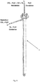
- Figures 1 to 3 show a section through a reactor according to the invention
- Figure 4 shows an external view of a reactor
- Figures 5 and 6th show a schematic representation of the reactor and process according to the invention.
- Figure 1 shows a reactor 1 according to the invention in the interior of which a metal-containing contact compound 2 is arranged.
- the metal-containing contact compound 2 essentially comprises a material that is reversibly oxidizable and reducible between a metallic form and an oxidic form.
- the reactor 1 has a feed line 3 with which water or water vapor can be brought into an inert region 7 in the end region of the reactor 1.
- the inert and reactive areas of the reactor space within the reactor tube 11 are connected to one another in a gas-conducting manner, so that water or steam supplied can reach the metal-containing contact mass 2 via the supply line.
- a synthesis gas region 8 is arranged in the reactor shown. This area is used to provide a gas mixture from a gasifiable carbon-containing starting material, that is able under suitable conditions (for example at a temperature of 300 ° C. to 1200 ° C.) to reduce metal oxide present in the metallic contact mass at least partially to metal.
- the gasifiable carbonaceous starting material can be introduced into the reactor space (either in the synthesis gas area or in an inert area 7 upstream of this area) directly on the tube sheet 12 of the reactor.
- An inert area 13 is provided between the synthesis gas area 8 and the metal-containing contact mass 2 (that is, the area in which hydrogen is obtained from water in the presence of metal).
- This additional inert area 13 has the advantage that any gaseous impurities that are still present in the synthesis gas area from the reduction or are formed as by-products during the oxidation cannot get into the hydrogen produced during the oxidation.
- any undesired impurities (for example solid carbon) from the synthesis gas region 8 or from the synthesis gas reaction are kept from penetrating into the metal-containing contact mass 2.
- the compressed hydrogen generated in the reactor according to the invention is preferably withdrawn from the reactor via a discharge line 4 which opens into an inert region 13 which is in gas-conducting connection with the metal-containing contact mass 2.
- the removal of the hydrogen from the inert area 13 is advantageous since a less contaminated hydrogen / water mixture can be obtained in this way.
- Fig. 2 a cross section of a reactor 1 according to the invention is shown.
- the method according to the invention can comprise an oxidation step or an oxidation and reduction step.
- a metal such as iron or metal oxide is brought into contact with water at a certain temperature, whereby metal oxide and hydrogen are produced.
- the metal oxide formed in the oxidation step is reduced to metal or a metal oxide by using a gasifiable carbonaceous starting material (eg methane with water).
- a gasifiable carbonaceous starting material eg methane with water.
- the in Fig. 2 Different lines for introducing and discharging gases and gas mixtures in and out of the reactor are used.
- water can be introduced directly or indirectly via the inert area 7 into the area with the metal-containing contact compound 2 via the opening A of the feed line 3.
- the hydrogen formed in the course of the oxidation or the hydrogen / water mixture formed is withdrawn from the reactor via opening 10 of the discharge line 4.
- all other supply lines and discharge lines in and out of the reactor except for supply line 3 are closed by means of devices for controlling or regulating the flow rate, preferably with a valve.
- Opening 10 of the discharge line 4 can additionally be connected to a water separator which can remove water contained in the compressed hydrogen.
- the feed line 3 is coupled to a means of conveying water-containing media.
- a gasifiable carbon-containing starting material eg methane with water
- the gasifiable carbonaceous starting material could alternatively be transported directly into the synthesis gas area 8.
- a discharge line 15 located on the reactor discharges the gas mixture (comprising, for example, CO 2 , CO, H 2 O and H 2 ) formed during the reduction of the metal-containing contact mass 2 from the reactor 1 via opening C.
- Fig. 3 shows a reactor 1 according to the invention without inserted regions.
- Fig. 4 the external view of a reactor 1 according to the invention is shown. Examples of fluids that are brought in and out of the reactor during the oxidation step or reduction step are shown together with the directions of flow.
- Fig. 5 shows schematically two images of the reactors according to the invention and the positions (open - white, closed - black) of the devices attached to the supply and discharge lines for controlling or controlling the flow rate, preferably the valves (5a, 5b, 5c, 5d).
- the valve on the feed line for introducing the gasifiable carbonaceous starting material (5a) is open.
- the gasifiable carbonaceous starting material flows through the synthesis gas area 8, the inert area 13 and the metal-containing contact mass 2 of the Reactor, wherein the gas mixture emerging from the reactor when the valve 5b is open can be used to heat the gasifiable carbonaceous starting material to be introduced and to heat the entire process.
- valve 5d is opened accordingly in order to remove compressed hydrogen from the reactor.
- Figure 6 shows an alternative embodiment of the reactor 1 according to the invention in which the area of partial oxidation 9 is integrated into the area of the metal-containing contact compound 2.
- the area of the partial oxidation 9 is located in a pipe or a line which is located within the area of the metal-containing contact compound 2.
- line 14 could be constructive Figure 2 be extended until shortly before the end of the reactor, and are filled with a solid.
- This arrangement is particularly useful when the synthesis gas is generated via an exothermic reaction (eg catalytic partial oxidation).
- C x H y + x / 2O 2 ⁇ xCO + y / 2H 2 (partial oxidation)
- the heat that is generated during the generation of synthesis gas is used to supply the endothermic reduction with energy.
- the exhaust gas from the reduction can also be used to generate process heat.
- the line with valve 5b in Figure 5 is optional in this case, but can be used for regeneration reactions or air oxidations if required.
- a device according to Fig. 6 can also have inert areas (7).
- the method according to the invention which is preferably carried out with the device according to the invention, comprises at least one oxidation step in which water is reacted with metal to form hydrogen and metal oxide.
- the contact mass is at least partially reduced as set out in the following general example.
- a hydrocarbon eg methane
- steam is mixed with steam and then passed through an area comprising inert material into the reactor, in which the gas mixture is brought to reaction temperature.
- the mixture then reaches the synthesis gas range.
- this area there is either a catalyst or a non-catalytic solid (metal oxide M w O z , where M stands for metal and w and z are integers) for the production of synthesis gas.
- metal oxide M w O z metal oxide
- M stands for metal and w and z are integers
- synthesis gas can be generated via reaction (2) C x H y + MO ⁇ xCO + y / 2 H 2 + M (2)
- C s solid carbon
- the first inert region has the function of a filter or absorber / adsorber.
- the synthesis gas is passed through the second inert area. If necessary, filter or absorber / adsorber material can also be used here.
- the synthesis gas then reaches the metal-containing contact mass. This is where the reduction of the metal oxide (here iron oxide as an example) takes place (5 and 6).
- the hydrogen is diverted through a second line (e.g. pipe) which opens into an inert area between the metal-containing contact mass and the synthesis gas area. Because the hydrogen is passed through this line, there can be no reaction with the impurities that are present in the synthesis gas area, and there is also no contamination of the hydrogen produced.
- the present steam / hydrogen mixture is fed into a condenser in which the steam condenses out. Any hydrogen pressure can be set by closing or limiting the gas flow at the condenser outlet.
Landscapes
- Chemical & Material Sciences (AREA)
- Organic Chemistry (AREA)
- Chemical Kinetics & Catalysis (AREA)
- Engineering & Computer Science (AREA)
- Combustion & Propulsion (AREA)
- Health & Medical Sciences (AREA)
- General Health & Medical Sciences (AREA)
- Inorganic Chemistry (AREA)
- Hydrogen, Water And Hydrids (AREA)
- Catalysts (AREA)
Description
- Die vorliegende Erfindung betrifft ein Verfahren zum Herstellen von komprimiertem Wasserstoff.
- Wasserstoff ist ein wichtiger Energieträger dessen Bedeutung in den letzten Jahren zugenommen hat, da bei der Verbrennung von Wasserstoff kaum Schadstoffe und keine Feinstaubpartikel anfallen. Eine derartig vorteilhafte Verbrennungsreaktion ist insbesondere bei Verbrennungsmotoren im Straßenverkehr wünschenswert. Zudem wird Wasserstoff in steigendem Maße zur Energiegewinnung in Brennstoffzellen eingesetzt. Derzeit wird der größte Teil des hergestellten Wasserstoffs jedoch in der chemischen Industrie eingesetzt.
- Wasserstoff wird heutzutage vorwiegend mithilfe von Dampfreformierung, partieller Oxidation und autothermer Reformierung hergestellt. In diesen Verfahren wird ein CO reiches Synthesegas produziert, so dass diese Verfahren oft mit der Wassergas-Shift-Reaktion kombiniert werden, um ein Gemisch aus Wasserstoff und Kohlendioxid herzustellen. Wird eine partielle Oxidation und autotherme Reformierung verwendet, wird zusätzlich Luft eingesetzt und der produzierte Wasserstoff ist zusätzlich mit großen Mengen and Stickstoff aus der Luft verdünnt. Um diesen zugesetzten Stickstoff, CO2, nicht umgesetztes CO und Ausgangsmaterial vom hergestellten Wasserstoff zu trennen, sind zusätzliche Reinigungsschritte notwendig. Diese Reinigung erfolgt üblicherweise durch Druckwechsel-Adsorption oder Monoethanolamin Gaswäsche.
- Die
GB 902,338 -
US2007/0217972 A1 beschreibt eine andere Vorrichtung und das entsprechende Verfahren zur Herstellung von komprimiertem Wasserstoff. -
DE 279726 aus dem Jahre 1913 beschreibt ein Verfahren zur Herstellung von Wasserstoff, bei dem überhitzter Wasserdampf über erhitzte Metalle geleitet wird. Die Retorte, in der dieses Verfahren durchgeführt wird, weist eine Öffnung zum Abführen des Wasserstoffs auf, an der eine mit Ventilen versehene Rohrleitung angeordnet ist. - In der
US 3,880,987 wird ein Verfahren zur Herstellung von komprimiertem Wasserstoff geoffenbart, bei dem Wasserdampf mit metallischem Zinn und Zinnoxid in Kontakt gebracht wird. - Die
DE 2507612 beschreibt ein Verfahren zur Herstellung von Wasserstoff, bei dem als Katalysator Wolframdioxid verwendet wird. Im Zuge dieses Verfahrens wird Wasserdampf bei einer Temperatur von weniger als 700 °C mit dem Katalysator in Kontakt gebracht. - Weitere Verfahren zur Herstellung von Wasserstoff umfassen die Verwendung von Membranreaktoren, Elektrolyse oder "Chemical looping"-Reaktionen.
- Sämtliche aus dem Stand der Technik bekannte Verfahren zur Herstellung von Wasserstoff weisen Nachteile unterschiedlicher Art auf. Einerseits wird mit diesen Verfahren mit Stickstoff, CO2, nicht umgesetztes CO und Ausgangsmaterial verunreinigter Wasserstoff hergestellt. Um diesen Wasserstoff zu reinigen benötigt man zusätzliche Verfahren und Vorrichtungen, wodurch die Herstellung von Wasserstoff mit diesen Verfahren zeit- und kostenintensiv ist. Mit Hilfe von Elektrolyse würde es zwar möglich sein, reinen Wasserstoff herzustellen, jedoch ist diese Art der Herstellung nur bei Verfügbarkeit von günstigen Stromquellen wirtschaftlich. Andererseits ist der mit diesen Verfahren hergestellte Wasserstoff üblicherweise nicht komprimiert. D.h. um komprimierten Wasserstoff herstellen zu können, wird zusätzlich eine Vorrichtung zum Komprimieren von Wasserstoff benötigt.
- Die Lagerung und der Transport von Wasserstoff stellt ein weiteres Problem dar. Üblicherweise wird Wasserstoff in Druckbehältern gelagert. Durch Verdichten mit Kompressoren und optionaler Kühlung kann Wasserstoff in verdichteter oder flüssiger Form in Druckbehältern eingebracht und eingelagert werden. Wesentliches Problem bei der Verflüssigung und Verdichtung von Wasserstoff ist der hohe Energieaufwand sowie der apparative Aufwand. Zusätzlich birgt diese Art der Lagerung das Risiko, dass die Behälter bzw. die daran angebrachten Ventile durch den hohen inneren Druck bersten können. Alternative Formen der Speicherung von Wasserstoff basieren auf Feststoffen oder Flüssigkeiten (z.B. Metallhydrid- und Adsorptionsspeicherung).
- Aufgabe der vorliegenden Erfindung ist es, u.a., ein alternatives Verfahren bzw. eine Vorrichtung zur Herstellung von komprimiertem Wasserstoff bereitzustellen, welches bzw. welche die Nachteile des Standes der Technik überwindet.
- Die vorliegende Erfindung betrifft eine Vorrichtung zum Herstellen von komprimiertem Wasserstoff umfassend einen druckstabilen Reaktor mit einem Reaktorraum, der eine metallhaltige Kontaktmasse aufweist, wobei der Reaktor mindestens eine Zuführleitung zum Zuführen von Fluiden in den Reaktorraum und mindestens eine Abführleitung zum Abführen von Fluiden aus dem Reaktorraum umfasst, wobei die mindestens eine Abführleitung mit einer Vorrichtung zur Steuerung oder Regelung der Durchflussmenge, vorzugsweise mit einem Ventil, zur Einstellung des Drucks innerhalb des Reaktorraums versehen ist, wobei an mindestens einer Zuführleitung ein Fördermittel zum Einbringen eines wasserhaltigen Mediums in einen Reaktorraum vorgesehen ist und wobei mindestens eine Abführleitung in den Reaktorraum ragt, über die komprimierter Wasserstoff aus dem Reaktorraum abgeführt wird, wobei der Reaktorraum mindestens zwei voneinander getrennte und gasleitend miteinander verbundene Bereiche aufweist, von denen mindestens ein Bereich die metallhaltige Kontaktmasse und mindestens ein weiterer Bereich mindestens ein inertes Material umfasst, wobei die in den Reaktorraum ragende Abführleitung in den Bereich umfassend das inerte Material mündet, und wobei im Reaktorraum mindestens ein Synthesegasbereich (8) angeordnet ist, der einen Katalysator und/oder einen nicht katalytischen Feststoff umfasst.
- Ein weiterer Aspekt der vorliegenden Erfindung betrifft ein Verfahren zum Herstellen von komprimiertem Wasserstoff in einer erfindungsgemäßen Vorrichtung umfassend einen Schritt des Einbringens eines wasserhaltigen Mediums in einen Reaktorraum eines druckstabilen Reaktors dieser Vorrichtung mittels eines Fördermittels, vorzugsweise einer Pumpe, wobei der Reaktorraum eine metallhaltige Kontaktmasse umfasst, wobei vor oder im Reaktorraum das wasserhaltige Medium verdampft wird, wodurch der Druck innerhalb des Reaktorraumes über den Umgebungsdruck steigt, und das verdampfte Wasser mit dem Metall der Kontaktmasse zu Wasserstoff und das Metall zu Metalloxid umgesetzt wird, wobei der komprimierte Wasserstoff über eine in den Reaktorraum ragende aus dem Reaktorraum abgeführt wird, wobei der Druck innerhalb des Reaktorraums mit einer an der Abführleitung vorgesehenen Vorrichtung zur Steuerung oder Regelung der Durchflussmenge, vorzugsweise mit einem Ventil, gesteuert oder geregelt wird, wobei die in den Reaktorraum ragende Leitung in den Bereich umfassend das inerte Material ragt und der komprimierte Wasserstoff über den Bereich umfassend das inerte Material aus dem Reaktorraum abgeführt wird, und wobei das Verfahren umfassend einen vom ersten Schritt der Umsetzung von verdampften Wasser mit dem Metall der Kontaktmasse zu Wasserstoff und des Metalls zu Metalloxid unabhängigen zweiten Schritt, in dem das Metalloxid der metallhaltigen Kontaktmasse aus dem ersten Schritt mit einem Gasgemisch umfassend Kohlenmonoxid und/oder Wasserstoff und/oder Methan und/oder langkettigen Kohlenwasserstoffe zu Metall reduziert wird.
- Die im erfindungsgemäßen Verfahren eingesetzten Reaktoren ermöglichen die Herstellung von komprimiertem Wasserstoff ohne die Verwendung von Kompressoren, die den üblicherweise bei Normaldruck hergestellten Wasserstoff, komprimieren. Erfindungsgemäß wird ein wasserhaltiges Medium (Wasser bzw. Wasserdampf) mit einer metallhaltigen Kontaktmasse in Kontakt gebracht. Durch die Oxidation des Metalls in der metallhaltigen Kontaktmasse bei einer Temperatur von vorzugsweise 300°C bis 1200°C, noch mehr bevorzugt 400°C bis 1000°C, besonders bevorzugt von 450°C bis 950°C, wird Wasserstoff freigesetzt. Die Vorrichtungen zur Steuerung oder Regelung der Durchflussmenge an den am Reaktor befindlichen Öffnungen ermöglichen es, dass der Druck innerhalb des Reaktors bedingt durch das Verdampfen des Wassers im Reaktorraum steigt. Der gebildete Wasserstoff liegt somit ebenfalls unter diesem Druck vor. Wird ein Fördermittel (z.B. Pumpe) zum Einbringen eines wasserhaltigen Mediums in den Reaktor verwendet, muss dieses durch Fördern des Mediums den Druck aufrecht halten und einen entsprechenden Gegendruck aufbauen. Wird ein bestimmter Druck innerhalb des Reaktorraums erreicht, kann mit einer Vorrichtung zur Steuerung oder Regelung der Durchflussmenge, vorzugsweise mit einem Ventil, der Reaktorraum im Bereich des Fördermittels geschlossen werden. Dadurch kann der im Zuge des Verfahrens innerhalb des Reaktors gebildete Druck aufrechterhalten und komprimierter Wasserstoff zu einem späteren Zeitpunkt aus dem Reaktor entnommen werden. Zudem kann mit der erfindungsgemäßen Vorrichtung zunächst eine bestimmte Menge Wasser oder Wasserdampf in den Reaktor eingebracht und dieser anschließend verschlossen werden. Durch die Zuführung von Wärme steigt der Druck innerhalb des Reaktorraums dementsprechend an. Im Gegensatz dazu wird bei den aus dem Stand der Technik bekannten Verfahren zur Wasserstoffherstellung der Druck in den entsprechenden Reaktoren dadurch erzeugt, in dem der Wasserdampf mit hohem Druck mit einer geeigneten Kontaktmasse in Kontakt gebracht wird. D.h. der Druckaufbau in solchen Systemen erfolgt durch das Einbringen des Dampfes mittels Drucks (siehe z.B.
GB 902,338 - Wird ein gewünschter Druck erreicht, wird beispielsweise das Ventil an einer Abführleitung geöffnet, wodurch Wasserstoff unter definiertem Druck abgelassen werden kann. Nach dem sich innerhalb des Reaktors ein gewünschter Druck aufgebaut hat, kann komprimierter Wasserstoff somit über eine mit einer Vorrichtung zur Steuerung oder Regelung der Durchflussmenge (z.B. Ventil) versehenen Leitung vom Reaktor direkt abgeführt werden. Das Abführen des komprimierten Wasserstoffs kann kontinuierlich erfolgen, in dem gleichzeitig zum Abführen, mit dem Fördermittel Wasser in den Reaktor eingebracht wird. Durch die Vorrichtung zur Steuerung oder Regelung der Durchflussmenge an der Abführöffnung kann die abgeführte Menge an komprimierten Wasserstoff bestimmt werden. Dadurch wird auch der Druck innerhalb des Reaktors gesteuert bzw. geregelt.
- Das Metall der metallhaltigen Kontaktmasse ist ein Metall, welches durch Wasserstoff, Kohlenmonoxid oder gasförmige Kohlenwasserstoffe unter den gegebenen Temperaturen zumindest teilweise reduziert, sowie mit Dampf unter Bildung von Wasserstoff zumindest teilweise oxidiert werden kann. Derartige Metalle sind dem Fachmann hinreichend bekannt, wobei Eisen, Wolfram, Molybdän und Germanium besonders geeignet sind.
- "Zumindest teilweise reduziert" bzw. "zumindest teilweise oxidiert", wie hierin verwendet, bedeutet, dass das Metall bzw. Metalloxid entweder vollständig oxidiert bzw. reduziert wird oder nur teilweise. Ein Beispiel für eine teilweise Reduktion ist z.B. die Reduktion von Fe3O4 zu FeO.
- Gemäß einer bevorzugten Ausführungsform der vorliegenden Erfindung wird der Druck innerhalb des Reaktorraums durch das Fördermittel und einer oder mehreren Vorrichtungen zur Steuerung der Durchflussmenge in Leitungen, die in und aus dem Reaktorraum führen, gesteuert.
- Der Druck innerhalb des Reaktorraums wird vorzugsweise durch das Fördermittel, mit dem das wasserhaltige Medium in den Reaktor eingebracht wird, gesteuert bzw. geregelt. Um einen entsprechenden Gegendruck im Reaktor zu erzeugen, wodurch der Druck innerhalb desselbigen über den Umgebungsdruck gesteigert werden kann, befinden sich an den Leitungen, die in und aus dem Reaktorraum führen, Vorrichtungen zur Steuerung bzw. Regelung der Durchflussmenge in diesen Leitungen. Vorrichtungen zur Steuerung der Durchflussmenge sind vorzugsweise Ventile. Besonders bevorzugt sind Sperrventile, Stromventile, Rückschlagventile, Druckventile und/oder Wegeventile.
- Gemäß einer weiteren bevorzugten Ausführungsform der vorliegenden Erfindung beträgt der Druck bei der Umsetzung von verdampften Wasser mit dem Metall der Kontaktmasse zu Wasserstoff und des Metalls bzw. der Metalle zu Metalloxid mindestens 2 bar, vorzugsweise von mindestens 3 bar, vorzugsweise von mindestens 4 bar, vorzugsweise von mindestens 5 bar, noch mehr bevorzugt von mindestens 6 bar, noch mehr bevorzugt von mindestens 7 bar, noch mehr bevorzugt von mindestens 8 bar, noch mehr bevorzugt von mindestens 9 bar, insbesondere von mindestens 10, 15, 20, 25, 30, 40, 50, 60, 70, 80, 90, 100, 150, 200, 250 oder 300 bar, beträgt. Besonders bevorzugt beträgt oder steigt der Druck während der Umsetzung bis auf maximal 400, 350, 300, 250, 200, 150, 100, 90, 80, 70, 60 oder 50 bar, abhängig von der Druckbeständigkeit des eingesetzten Reaktors, der Leitungen und den Anschlüssen zu den Vorrichtungen zur Steuerung der Durchflussmenge. Zudem beträgt der Druck während der Umsetzung bevorzugt zwischen 2 und 400 bar, zwischen 2 und 350 bar, zwischen 2 und 300 bar, zwischen 2 und 250 bar, zwischen 2 und 200 bar, zwischen 2 und 150 bar, zwischen 2 und 100 bar, zwischen 2 und 80 bar, zwischen 2 und 60 bar, zwischen 5 und 400 bar, zwischen 5 und 400 bar, zwischen 5 und 400 bar, zwischen 5 und 350 bar, zwischen 5 und 300 bar, zwischen 5 und 250 bar, zwischen 5 und 200 bar, zwischen 5 und 150 bar, zwischen 5 und 100 bar, zwischen 5 und 80 bar oder zwischen 5 und 60 bar. Besonders bevorzugt ist ein Druckbereich zwischen 2 und 250 bar, noch mehr bevorzugt zwischen 5 und 200 bar.
- Die metallhaltige Kontaktmasse weist vorzugsweise die Form eines Metallschwamms, Pellets, Pulvers, Granulats oder eine Kombination davon auf. Verfahren zur Herstellung derartiger Kontaktmassen sind dem Fachmann hinreichend bekannt. Die metallhaltige Kontaktmasse, die mit dem Wasser des wasserhaltigen Mediums bzw. dem Wasserdampf in Kontakt gebracht wird, kann im Prinzip jegliche Form aufweisen. Besonders bevorzugt sind Kontaktmassen, die mechanisch stabil sind und für die Umsetzung von Wasser zu Wasserstoff geeignet große Oberfläche aufweisen.
- Gemäß einer bevorzugten Ausführungsform der vorliegenden Erfindung umfasst die metallhaltige Kontaktmasse ein Metall und/oder Metalloxid ausgewählt aus der Gruppe bestehend aus Eisen, Eisenoxid, Molybdän, Molybdänoxid, Wolfram, Wolframoxid, Germanium, Germaniumoxid und Kombinationen davon. Besonders bevorzugt ist die Verwendung von Eisen bzw. Eisenoxid in der metallhaltigen Kontaktmasse.
- Die erfindungsgemäß verwendete metallhaltige Kontaktmasse kann die zuvor erwähnten Metalle bzw. Metalloxide in beliebiger Menge und in beliebigen Mengenverhältnissen umfassen.
- Gemäß einer bevorzugten Ausführungsform der vorliegenden Erfindung umfasst die Kontaktmasse zusätzliche Metalloxide, um die Stabilität und Reaktivität der Kontaktmasse zu erhöhen. Geeignete zusätzliche Metalloxide sind vorzugsweise ausgewählt aus der Gruppe bestehend aus CoO, GeO2, CuO, NiO2, PtO2, Na2O, In2O3, Li2O, WO3, Ag2O, ZnO, RuO, NiO, Fe2O3, RuO2, Ga2O3, PtO, Nb2O5, MnO2, In2O3, PdO, K2O, SnO2, TiO2, Cr2O3, HfO, ZrO2, VO2, CeO2, Y2O3, CaO, MoO2, SiO2, La2O3, MgO, Sc2O3, SrO, Al2O3 und Kombinationen davon. Vorzugsweise ist der Anteil der aktiven Metalle (wie Eisen, Molybdän, Wolfram und Germanium) in der metallhaltigen Kontaktmasse höher als jener der nicht-reaktiven Zusatzstoffe bzw. Metalloxide (wie z.B. Al2O3 und ZrO2). Dementsprechend umfasst die metallhaltige Kontaktmasse mindestens 60%, vorzugsweise mindestens 70%, vorzugsweise mindestens 80%, vorzugsweise mindestens 90%, vorzugsweise mindestens 95%, noch mehr bevorzugt mindestens 99%, aktive Metalle. "Aktiv" in diesem Zusammenhang bedeutet, dass das Material/Metall durch Wasserstoff, Kohlenmonoxid oder gasförmige Kohlenwasserstoffe unter den gegebenen Temperaturen zumindest teilweise reduziert, sowie mit Dampf unter Bildung von Wasserstoff zumindest teilweise oxidiert werden kann.
- Gemäß der vorliegenden Erfindung weist der Reaktorraum mindestens zwei voneinander getrennte und gasleitend miteinander verbundene Bereiche auf, von denen mindestens ein Bereich die metallhaltige Kontaktmasse und mindestens ein weiterer Bereich mindestens ein inertes Material umfasst.
- Die in den Reaktorraum ragende Leitung ragt in den Bereich umfassend das inerte Material und der komprimierte Wasserstoff wird über den Bereich umfassend das inerte Material aus dem Reaktorraum abgeführt. Dadurch wird es ermöglicht, dass der aus dem Reaktorraum gewonnene Wasserstoff weniger Verunreinigungen aufweist, als herkömmlich hergestellter Wasserstoff.
- Die im Reaktorraum der erfindungsgemäßen Vorrichtung befindliche Kontaktmasse verbleibt während des gesamten Verfahrens und während dessen Reduktion nach der Wasserstoffherstellung im erfindungsgemäßen Reaktor. Dies hat den Vorteil, dass die Kontaktmasse nicht in einen Regenerationsreaktor überführt und somit bewegt werden muss. Der Bereich des Reaktorraums, der die Kontaktmasse umfasst, ist somit als Festbettreaktor anzusehen. Die Tatsache, dass sowohl Oxidation als auch Reduktion der Kontaktmasse in ein und denselben Reaktorraum durchgeführt wird, hat somit Vorteile gegenüber herkömmlichen Vorrichtungen wie in der
GB 902,338 - Im erfindungsgemäßen Verfahren wird aus Wasserdampf bzw. Wasser Wasserstoff gewonnen. Überschüssiges Wasser wird vorzugsweise vom hergestellten komprimierten Wasserstoff abgetrennt, in dem der vom Reaktor abgeführte komprimierte Wasserstoff einem Wasserdampfabscheider zugeführt wird. Durch diesen Verfahrensschritt wird vorzugsweise zumindest 10%, noch mehr bevorzugt mindestens 20%, noch mehr bevorzugt mindestens 30%, noch mehr bevorzugt mindestens 40%, noch mehr bevorzugt mindestens 50%, noch mehr bevorzugt mindestens 60%, noch mehr bevorzugt mindestens 70%, noch mehr bevorzugt mindestens 80%, noch mehr bevorzugt mindestens 90%, noch mehr bevorzugt mindestens 95%, insbesondere 100%, des Wassers des im aus dem Reaktor austretenden Wasserstoff/Wassergemisches entfernt. Die Wasserdampfabscheidung beruht gemäß einer bevorzugten Ausführungsform der vorliegenden Erfindung auf einem Kondensator.
- Das erfindungsgemäße Verfahren umfasst einen ersten Schritt bei dem Wasser in Anwesenheit von Metall zu Wasserstoff und das Metall zu einem Metalloxid umgesetzt wird. Um das Metalloxid aus diesem ersten Schritt zu Metall zu reduzieren und somit die metallhaltige Kontaktmasse zu "regenerieren", wird ein weiterer Verfahrensschritt durchgeführt. Dadurch wird das in einem ersten Schritt entstandene Metalloxid regeneriert bzw. reduziert. Der Schritt des "Regenerierens" erfolgt erfindungsgemäß im Reaktorraum der erfindungsgemäßen Vorrichtung, wodurch es nicht erforderlich ist die zu regenerierende Kontaktmasse aus dem Reaktor zu entfernen. Bei herkömmlichen Verfahren, wie z.B. in der
GB 902,338 - Gemäß einer weiteren bevorzugten Ausführungsform der vorliegenden Erfindung umfasst das erfindungsgemäße Verfahren einen vom ersten Schritt der Umsetzung von verdampften Wasser mit dem Metall der Kontaktmasse zu Wasserstoff und des Metalls zu Metalloxid unabhängigen zweiten Schritt, in dem das Metalloxid der metallhaltigen Kontaktmasse aus dem ersten Schritt mit einem Gasgemisch umfassend Kohlenmonoxid und/oder Wasserstoff und/oder Methan und/oder langkettigen Kohlenwasserstoffe zumindest teilweise zu Metall reduziert wird. Derartige Gasgemische entstehen z.B. bei der Herstellung von Synthesegas aus Erdölfraktionen wie Diesel wie unten beschrieben. "Langkettige Kohlenwasserstoffe", wie hierin verwendet, umfassen Kohlenwasserstoffe mit mehr als einem Kohlenstoffatom, vorzugsweise mit einer Kettenlänge von mehr als 2, 3, 4 oder 5 Kohlenstoffatomen. Geeignete Gasgemische können auch Alkohole von Kohlenwasserstoffen umfassen (wie z.B. Methanol oder Ethanol).
- Die Oxidationsreaktion kann abwechselnd zur Reduktionsreaktion im selben Reaktor durchgeführt werden. Dadurch kann der Prozess der Herstellung von komprimiertem Wasserstoff kontinuierlich erfolgen, wenn in mindestens zwei Reaktoren versetzt zueinander das erfindungsgemäße Verfahren durchgeführt wird. Abwechselnd findet in jedem der Reaktoren ein Reduktions- und ein Oxidationsschritt statt. Im Anschluss des jeweiligen Reaktionsschritts wird der andere Reaktionsschritt durchgeführt.
- Gemäß einer bevorzugten Ausführungsform der vorliegenden Erfindung wird das Gasgemisch umfassend Kohlenmonoxid und Wasserstoff in einem vorzugsweise innerhalb des Reaktorraumes befindlichen Synthesegasbereichs, der einen Katalysator und/oder einen nicht-katalytischen Feststoff umfasst, aus einem vergasbaren kohlenstoffhaltigen Ausgangsmaterial hergestellt und in den Bereich umfassend die zumindest teilweise oxidierte metallhaltige Kontaktmasse geleitet.
- Erfindungsgemäß kann jegliche Quelle für ein Gasgemisch umfassend Kohlenmonoxid und/oder Wasserstoff und/oder Methan und/oder langkettigen Kohlenwasserstoffe eingesetzt werden, um das oxidierte Metall der metallischen Kontaktmasse bzw. die Metalloxide zumindest teilweise zu reduzieren. Es ist jedoch besonders bevorzugt, wenn das Gasgemisch umfassend Kohlenmonoxid und Wasserstoff bzw. das Synthesegas direkt im Reaktor selbst hergestellt wird. Dadurch könnten vergasbare kohlenstoffhaltige Ausgangsmaterialien direkt in den Reaktor eingesetzt werden, wodurch ein zusätzlicher Synthesegasreaktor eingespart werden kann.
- Als "vergasbare kohlenstoffhaltige Ausgangsmaterialien" können sämtliche für die Herstellung von Synthesegas bekannten Stoffe und Stoffgemische verwendet werden, die entweder fest, flüssig oder gasförmig sind. Feste vergasbare Ausgangsmaterialen können beispielsweise Kohle oder Biomasse, wie Holz oder Stroh, sein. Als flüssige Edukte für Synthesegas können Rohöldestillate (leichtsiedende und/oder hochsiedende Fraktionen), aber auch Alkohole (wie z.B. Methanol, Ethanol oder Propanol) eingesetzt werden. Gasförmige Ausgangsmaterialien umfassen u.a. Methan, Biogas, Erdgas und/oder Flüssiggas. Zu diesen Ausgangsmaterialien werden im Bedarfsfall zusätzlich Oxidationsmittel (z.B. Luft und/oder Sauerstoff und/oder Wasserdampf und/oder Kohlendioxid) dazugegeben.
- Der Synthesegasbereich innerhalb des erfindungsgemäßen Reaktors umfasst vorzugsweise einen Katalysator, der vorzugsweise ausgewählt ist aus der Gruppe bestehend aus Metallen, Metalloxiden und Kombinationen davon, insbesondere Nickel, Kobalt, Ruthenium, Platin, Palladium, Gold, Eisen, MgO, Al2O3, SiO2, CuO oder CeO2. Selbstverständlich können im erfindungsgemäßen Verfahren jegliche Art und Form von Katalysatoren eingesetzt werden, die üblicherweise bei der Herstellung von Synthesegas verwendet werden.
- Wird im erfindungsgemäßen Verfahren ein nicht-katalytischer Feststoff im Synthesegasbereich eingesetzt so ist dieser vorzugsweise ausgewählt aus der Gruppe bestehend aus Nickeloxid, Eisenoxid, Kupferoxid, Wolframoxid und Kombinationen davon. Der nicht-katalytische Feststoff muss nicht mit Wasserdampf zu Metalloxid und Wasserstoff reagieren können. Daher sind auch z.B. Nickel und Kupfer möglich. Der nicht-katalytische Feststoff soll mit Luft, z.B., wieder zu seinem Oxid oxidiert werden können (Regenerationsschritt analog zur Dampfoxidation von z.B. Eisen im Reaktorbereich, der die metallhaltige Kontaktmasse umfasst).
- Um die Energieeffizienz des erfindungsgemäßen Verfahrens zu verbessern ist es besonders bevorzugt, das im zweiten Schritt, dem "Reduktionsschritt" (Reduktion des oxidierten Metalls der metallhaltigen Kontaktmasse), entstehende Gasgemisch ("Abgas") aus dem Reaktor abzuführen und zur Temperierung des Reaktors und/oder des in den Reaktor einzubringenden kohlenstoffhaltigen Ausgangsmaterial zu verwenden. Dabei kann einerseits die Abwärme des aus dem Reaktor abgeführten Gasgemisches verwendet werden oder das Gasgemisch ("Abgas") selbst wird zur Wärmegewinnung verbrannt.
- Gemäß einer besonders bevorzugten Ausführungsform der vorliegenden Erfindung wird das Gasgemisch umfassend Kohlenmonoxid und Wasserstoff in einem innerhalb des Reaktorraumes befindlichen Bereichs zur partiellen Oxidation eines kohlenstoffhaltigen Ausgangsmaterials, der gegebenenfalls einen Katalysator für die partielle Oxidation umfasst, aus einem kohlenstoffhaltigen Ausgangsmaterial hergestellt und in den Bereich umfassend die zumindest teilweise oxidierte metallhaltige Kontaktmasse geleitet.
- Der Katalysator für die partielle Oxidation ist vorzugsweise ausgewählt aus der Gruppe bestehend aus Metallen, Metalloxiden und Kombinationen davon, insbesondere Nickel, Kobalt, Ruthenium, Platin, Palladium, Gold, Eisen, MgO, Al2O3, SiO2, CuO oder CeO2.
- Bei der partiellen Oxidation wird ein unterstöchiometrisches Brennstoff-Luft-Gemisch in Anwesenheit eines Katalysators teilweise verbrannt, wobei ein wasserstoffreiches Synthesegas entsteht. Um die Bildung von elementarem Kohlenstoff zu reduzieren bzw. zu unterbinden wird bei der partiellen Oxidation vorzugsweise Wasser und/oder Wasserdampf beigemischt.
- Gemäß einer bevorzugten Ausführungsform der vorliegenden Erfindung wird die partielle Oxidation in mindestens einem Reaktionsbereich, vorzugsweise einer Leitung, im Reaktorraum durchgeführt, wobei der mindestens eine Reaktionsbereich durch den Bereich umfassend die metallhaltige Kontaktmasse geführt wird, um die bei der partiellen Oxidation entstehende Wärme zur Erwärmung der metallhaltigen Kontaktmasse zu nutzen. Durch diese Vorgehensweise wird die Energieeffizienz des erfindungsgemäßen Verfahrens signifikant gesteigert, da die Wärme, die für die Reduktion der metallhaltigen Kontaktmasse benötigt wird, nicht am isolierten und druckverstärkten Außenmantel des Reaktors eingebracht werden muss, sondern im Inneren des Reaktors. Besonders vorteilhaft ist es, wenn mehrere Reaktionsbereiche für die partielle Oxidation, vorzugsweise mehrere Leitungen, die metallhaltige Kontaktmasse durchdringen.
- Gemäß einer bevorzugten Ausführungsform der vorliegenden Erfindung wird der Synthesegasbereich oder der Bereich zur partiellen Oxidation eines kohlenstoffhaltigen Ausgangsmaterials von der metallhaltigen Kontaktmasse durch einen gasdurchlässigen inerten Bereich getrennt. Dadurch wird im erfindungsgemäßen Verfahren das im Synthesegasbereich oder im Bereich der partiellen Oxidation gebildete Gas bzw. Gasgemisch zunächst vorzugsweise in einen inerten Bereich innerhalb des Reaktorraums und anschließend zur metallhaltigen Kontaktmasse geführt. Diese Gasführung hat den Vorteil, dass eventuell bei der Herstellung des Synthesegases bzw. bei der partiellen Oxidation entstehender fester Kohlenstoff oder auch sonstige Verunreinigungen (z.B. Schwefelverbindungen) nicht in den Bereich der metallhaltigen Kontaktmasse gelangen, wodurch die Effizienz der Wasserstoffherstellung durch etwaige Verunreinigungen im Wesentlichen unbeeinträchtigt bleibt und die Reinheit des Wasserstoffes erhöht werden kann.
- Gemäß einer weiteren bevorzugten Ausführungsform der vorliegenden Erfindung wird der komprimierte Wasserstoff aus dem inerten Bereich zwischen dem Synthesegasbereich oder dem Bereich zur partiellen Oxidation eines kohlenstoffhaltigen Ausgangsmaterials aus dem Reaktorraum abgeführt. Durch das Abführen des komprimierten Wasserstoffs aus dem zuvor genannten inerten Bereichs aus dem Reaktorraum ist es möglich hochreinen komprimierten Wasserstoff herzustellen.
- Gemäß einer bevorzugten Ausführungsform der vorliegenden Erfindung weist die metallhaltige Kontaktmasse der erfindungsgemäßen Vorrichtung die Form eines Metallschwamms, Pellets, Pulvers, Granulats oder eine Kombination davon auf.
- Gemäß einer weiteren bevorzugten Ausführungsform der vorliegenden Erfindung umfasst die metallhaltige Kontaktmasse ein Metall und/oder Metalloxid ausgewählt aus der Gruppe bestehend aus Eisen, Eisenoxid, Molybdän, Molybdänoxid, Wolfram, Wolframoxid, Germanium, Germaniumoxid und Kombinationen davon.
- Um die Stabilität und Reaktivität der Kontaktmasse zu erhöhen umfasst die Kontaktmasse vorzugsweise zusätzliche Metalloxide.
- Gemäß einer bevorzugten Ausführungsform der vorliegenden Erfindung sind die zusätzlichen Metalloxide ausgewählt aus der Gruppe bestehend aus CoO, GeO2, CuO, NiO2, PtO2, Na2O, In2O3, Li2O, WO3, Ag2O, ZnO, RuO, NiO, Fe2O3, RuO2, Ga2O3, PtO, Nb2O5, MnO2, In2O3, PdO, K2O, SnO2, TiO2, Cr2O3, HfO, ZrO2, VO2, CeO2, Y2O3, CaO, MoO2, SiO2, La2O3, MgO, Sc2O3, SrO, Al2O3 und Kombinationen davon.
- Gemäß einer besonders bevorzugten Ausführungsform der vorliegenden Erfindung weist der Reaktorraum mindestens zwei voneinander getrennte und gasleitend miteinander verbundene Bereiche auf, von denen mindestens ein Bereich die metallhaltige Kontaktmasse und mindestens ein weiterer Bereich mindestens ein inertes Material umfasst.
- Gemäß der vorliegenden Erfindung mündet die in den Reaktorraum ragende Abführleitung in den Bereich umfassend das inerte Material.
- Der erfindungsgemäße Reaktor weist Zuführleitungen und Abführleitungen auf mit denen Fluide (Gase und Flüssigkeiten wie z.B. Wasser) in den Reaktor eingebracht werden können. Vorzugsweise münden diese Leitungen in einem Bereich umfassend ein inertes Material. D.h. dass die in den Reaktor einbringbaren Fluide nicht unmittelbar mit einem chemisch reaktiven Material in Kontakt gebracht werden.
- Die in den Reaktorraum ragende Abführleitung, mit der Fluide wie z.B. der komprimierte Wasserstoff aus dem Reaktor abgeführt werden können, ist vorzugsweise mit einem Wasserdampfabscheider verbunden. Der Wasserdampfabscheider dient dazu im komprimierten Wasserstoff enthaltenes Wasser abzutrennen, um reineren Wasserstoff zu erzeugen.
- Im Reaktorraum ist mindestens ein Synthesegasbereich angeordnet, der einen Katalysator und/oder einen nicht-katalytischen Feststoff umfasst. Neben dem mindestens einen Bereich mit metallischer Kontaktmasse im Reaktorraum ist zusätzlich mindestens ein Synthesegasbereich angeordnet. Diese beiden Bereiche sind räumlich voneinander getrennt, jedoch gasleitend miteinander verbunden. Dadurch können die unterschiedlichen chemischen Reaktionen in den jeweiligen Bereichen im Reaktorraum getrennt erfolgen.
- Der Katalysator des Synthesegasbereichs ist vorzugsweise ausgewählt aus der Gruppe bestehend aus Metallen, Metalloxiden und Kombinationen davon, insbesondere Nickel, Kobalt, Ruthenium, Platin, Palladium, Gold, Eisen, MgO, Al2O3, SiO2, CuO oder CeO2.
- Der nicht-katalytische Feststoff des Synthesegasbereichs ist vorzugsweise ausgewählt aus der Gruppe bestehend aus Nickeloxid, Eisenoxid, Kupferoxid, Wolframoxid und Kombinationen davon.
- Gemäß einer weiteren bevorzugten Ausführungsform der vorliegenden Erfindung ist im Reaktorraum mindestens ein Bereich zur partiellen Oxidation eines kohlenstoffhaltigen Ausgangsmaterials angeordnet, der einen Katalysator für die partielle Oxidation umfasst.
- Gemäß einer bevorzugten Ausführungsform der vorliegenden Erfindung ist der Katalysator für die partielle Oxidation ausgewählt aus der Gruppe bestehend aus Metallen, Metalloxiden und Kombinationen davon, insbesondere Nickel, Kobalt, Ruthenium, Platin, Palladium, Gold, Eisen, MgO, Al2O3, SiO2, CuO oder CeO2.
- Der Reaktorraum weist vorzugsweise mehrere Bereiche zur partiellen Oxidation in Form von Leitungen auf, wobei die Leitungen durch den Bereich umfassend die metallhaltige Kontaktmasse geführt sind. Bei der partiellen Oxidation wird ein unterstöchiometrisches Brennstoff-Luft-Gemisch teilweise verbrannt und es entsteht ein wasserstoffreiches Synthesegas. Die bei der partiellen Oxidation entstehende Wärme kann zur Erwärmung der metallhaltigen Kontaktmasse verwendet werden. Dadurch kann die Energieeffizienz bei der Wasserstoffherstellung verbessert werden. Besonders bevorzugt ist das Vorsehen von mehr als einer Leitung (z.B. mehr als zwei, mehr als drei, mehr als vier, mehr als fünf, mehr als sechs, mehr als acht, mehr als zehn, mehr als 15, mehr als 20, mehr als 30), in der eine partielle Oxidation durchgeführt werden kann, innerhalb der metallhaltigen Kontaktmasse.
- Gemäß einer bevorzugten Ausführungsform der vorliegenden Erfindung ist der Synthesegasbereich oder der Bereich zur partiellen Oxidation von der metallhaltigen Kontaktmasse durch einen gasdurchlässigen inerten Bereich getrennt.
- Gemäß einer weiteren bevorzugten Ausführungsform der vorliegenden Erfindung ist eine Öffnung der mindestens einen in den Reaktorraum ragenden Abführleitung im inerten Bereich zwischen dem Synthesegasbereich oder dem Bereich zur partiellen Oxidation und dem Bereich der Kontaktmasse angeordnet.
- Durch das Abführen des Wasserstoffs aus dem inerten Bereich ist es möglich Wasserstoff von höherer Reinheit herzustellen als bei der Entnahme des Wasserstoffs direkt aus dem Synthesegasbereich oder dem Bereich zur partiellen Oxidation. Deshalb ist es besonders bevorzugt, wenn die Öffnung oder die Öffnungen der Abführleitung bzw. Abführleitungen im inerten Bereich vorzufinden ist.
- Die vorliegende Erfindung wird anhand der folgenden Figuren eingehender dargelegt, ohne jedoch auf diese beschränkt zu sein.
-
Figuren 1 bis 3 zeigen einen Schnitt durch einen erfindungsgemäßen Reaktor;Figur 4 zeigt eine Außenansicht eines Reaktors;Figuren 5 und6 zeigen eine schematische Darstellung des erfindungsgemäßen Reaktors und Verfahrens. -
Figur 1 zeigt einen erfindungsgemäßen Reaktor 1 in dessen Inneren eine metallhaltige Kontaktmasse 2 angeordnet ist. Die metallhaltige Kontaktmasse 2 umfasst im Wesentlichen ein zwischen einer metallischen Form und einer oxidischen Form reversibel oxidierbares und reduzierbares Material. Der Reaktor 1 weist eine Zuführleitung 3 auf mit der Wasser bzw. Wasserdampf in einen inerten Bereich 7 im Endbereich des Reaktors 1 gebracht werden kann. Die inerten und reaktiven Bereiche des Reaktorraums innerhalb des Reaktorrohres 11 sind gasleitend miteinander verbunden, so dass über die Zuleitung zugeführtes Wasser bzw. zugeführter Wasserdampf zur metallhaltigen Kontaktmasse 2 gelangen kann. - In dem in
Figur 1 dargestellten Reaktor ist ein Synthesegasbereich 8 angeordnet. Dieser Bereich dient dazu aus einem vergasbaren kohlenstoffhaltigen Ausgangsmaterial ein Gasgemisch bereitzustellen, das in der Lage ist bei geeigneten Bedingungen (z.B. bei einer Temperatur von 300°C bis 1200°C) in der metallischen Kontaktmasse vorhandenes Metalloxid zumindest teilweise zu Metall zu reduzieren. Das vergasbare kohlenstoffhaltige Ausgangsmaterial kann direkt am Rohrboden 12 des Reaktors in den Reaktorraum (entweder in den Synthesegasbereich oder einem diesem Bereich vorgelagerten inerten Bereich 7) eingebracht werden. Zwischen dem Synthesegasbereich 8 und der metallhaltigen Kontaktmasse 2 (das ist jener Bereich, in dem in Anwesenheit von Metall aus Wasser Wasserstoff gewonnen wird) ist ein inerter Bereich 13 vorgesehen. Dieser zusätzliche inerte Bereich 13 hat den Vorteil, dass etwaige gasförmige Verunreinigungen die im Synthesegasbereich noch von der Reduktion vorhanden sind bzw. während der Oxidation als Nebenprodukte gebildet werden können nicht in den bei der Oxidation produzierten Wasserstoff gelangen. Zusätzlich werden etwaige unerwünschte Verunreinigungen (z.B. fester Kohlenstoff) aus dem Synthesegasbereich 8 bzw. aus der Synthesegasreaktion vor dem Eindringen in die metallhaltige Kontaktmasse 2 abgehalten. - Der im erfindungsgemäßen Reaktor erzeugte komprimierte Wasserstoff wird vorzugsweise über eine Abführleitung 4 aus dem Reaktor entnommen, welche in einen inerten Bereich 13 mündet, der gasleitend mit der metallhaltigen Kontaktmasse 2 in Verbindung steht. Die Entnahme des Wasserstoffs aus dem inerten Bereich 13 ist vorteilhaft, da dadurch ein weniger verunreinigtes Wasserstoff/Wassergemisch gewonnen werden kann.
- In
Fig. 2 ist ein Querschnitt eines erfindungsgemäßen Reaktors 1 dargelegt. Wie eingangs ausgeführt kann das erfindungsgemäße Verfahren einen Oxidationsschritt oder einen Oxidations- und Reduktionsschritt umfassen. Im Oxidationsschritt wird ein Metall, wie z.B. Eisen, oder Metalloxid bei einer bestimmten Temperatur mit Wasser in Kontakt gebracht, wodurch Metalloxid und Wasserstoff produziert wird. Im Reduktionsschritt wird das im Oxidationsschritt gebildete Metalloxid, zu Metall oder einem Metalloxid reduziert, in dem ein vergasbares kohlenstoffhaltiges Ausgangsmaterial (z.B. Methan mit Wasser) eingesetzt wird. Je nach Verfahrensschritt können bei der inFig. 2 dargestellten Vorrichtung unterschiedliche Leitungen zum Ein- und Ausbringen von Gasen und Gasgemischen in und aus dem Reaktor eingesetzt werden. - Während des Oxidationsschritts kann über die Öffnung A der Zuführleitung 3 Wasser direkt oder indirekt über den inerten Bereich 7 in den Bereich mit der metallhaltigen Kontaktmasse 2 eingebracht werden. Der im Zuge der Oxidation gebildete Wasserstoff bzw. das entstehende Wasserstoff/Wassergemisch wird über Öffnung 10 der Abführleitung 4 aus dem Reaktor entnommen. Um den Druck während der Oxidation innerhalb des Reaktors bzw. Reaktorraums zu steigern sind bis auf Zuführleitung 3 sämtliche weiteren Zuführleitungen und Abführleitungen in und aus dem Reaktor mittels daran befindlichen Vorrichtungen zur Steuerung oder Regelung der Durchflussmenge, vorzugsweise mit einem Ventil, verschlossen. Öffnung 10 der Abführleitung 4 kann zusätzlich mit einem Wasserabscheider verbunden sein, der im komprimierten Wasserstoff befindliches Wasser entfernen kann. Die Zuführleitung 3 ist an ein Fördermittel von wasserhaltigen Medien gekoppelt.
- Im Zuge des Reduktionsschrittes wird ein vergasbares kohlenstoffhaltiges Ausgangsmaterial (z.B. Methan mit Wasser) durch Öffnung B einer Zuführleitung 14 über einen inerten Bereich 7 in den Synthesegasbereich 8 eingebracht. Das vergasbare kohlenstoffhaltige Ausgangsmaterial könnte alternativ dazu direkt in den Synthesegasbereich 8 transportiert werden. Eine am Reaktor befindliche Abführleitung 15 führt das bei der Reduktion der metallhaltigen Kontaktmasse 2 entstehende Gasgemisch (umfassend z.B. CO2, CO, H2O und H2) über Öffnung C aus dem Reaktor 1 ab.
-
Fig. 3 zeigt einen erfindungsgemäßen Reaktor 1 ohne eingefügte Bereiche. - In
Fig. 4 ist die Außenansicht eines erfindungsgemäßen Reaktors 1 abgebildet. Beispielhafte Fluide, die während des Oxidationsschrittes bzw. Reduktionsschrittes aus dem Reaktor aus- und eingebracht werden, sind gemeinsam mit den Strömungsrichtungen eingezeichnet. -
Fig. 5 zeigt schematisch zwei Abbildungen der erfindungsgemäßen Reaktoren und die Positionen (offen - weiß, geschlossen - schwarz) der an den Zuführ- und Abführleitungen angebrachten Vorrichtungen zur Steuerung oder Steuerung der Durchflussmenge, vorzugsweise der Ventile (5a, 5b, 5c, 5d). Während der Reduktionsreaktion ist das Ventil an der Zuführleitung zum Einbringen des vergasbaren kohlenstoffhaltigen Ausgangsmaterials (5a) (z.B. Methan/Wasser) geöffnet. Dabei strömt das vergasbare kohlenstoffhaltige Ausgangsmaterial durch den Synthesegasbereich 8, den inerten Bereich 13 und die metallhaltige Kontaktmasse 2 des Reaktors, wobei das bei geöffneten Ventil 5b aus dem Reaktor austretende Gasgemisch dazu verwendet werden kann, um das einzubringende vergasbare kohlenstoffhaltigen Ausgangsmaterials zu erwärmen und den gesamten Prozess zu beheizen. - Während der Oxidationsreaktion werden - um den Druck innerhalb des Reaktors zu erhöhen - bis auf das Ventil 5c an der Einführleitung für Wasser in den Reaktor sämtliche Öffnungen verschlossen. Ventil 5d wird nach Erreichen eines vordefinierten Drucks innerhalb des Reaktors entsprechend geöffnet, um komprimierten Wasserstoff aus dem Reaktor zu entnehmen.
-
Figur 6 zeigt eine alternative Ausgestaltung des erfindungsgemäßen Reaktors 1 bei dem der Bereich der partiellen Oxidation 9 in den Bereich der metallhaltigen Kontaktmasse 2 integriert ist. Der Bereich der partiellen Oxidation 9 befindet sich in einem Rohr bzw. einer Leitung, welche sich innerhalb des Bereichs der metallhaltigen Kontaktmasse 2 befindet. Konstruktiv könnte im einfachsten Fall Leitung 14 ausFigur 2 bis kurz vor Reaktorende verlängert werden, und mit einem Feststoff befüllt werden. Diese Anordnung ist speziell dann sinnvoll, wenn die Erzeugung des Synthesegases über eine exotherme Reaktion stattfindet (z.B. katalytische partielle Oxidation).
CxHy + x/2O2 → xCO + y/2H2 (partielle Oxidation)
- In diesem Fall wird die Wärme, die bei der Synthesegaserzeugung entsteht, verwendet, um die endotherme Reduktion mit Energie zu versorgen. Abgas der Reduktion kann zusätzlich zur Gewinnung von Prozesswärme verwendet werden. Die Leitung mit Ventil 5b in
Figur 5 ist in diesem Fall optional, kann aber bei Bedarf für Regenerationsreaktionen bzw. Luftoxidationen verwendet werden. - Eine Vorrichtung gemäß
Fig. 6 kann ebenfalls inerte Bereiche (7) aufweisen. - Das erfindungsgemäße Verfahren, das vorzugsweise mit der erfindungsgemäßen Vorrichtung durchgeführt wird, umfasst zumindest einen Oxidationsschritt bei dem Wasser mit Metall zu Wasserstoff und Metalloxid umgesetzt wird. Um das Metalloxid zumindest teilweise zu Metall zu reduzieren und somit die metallhaltige Kontaktmasse für den nächsten Oxidationszyklus zu regenerieren, wird die Kontaktmasse zumindest teilweise reduziert wie im Folgenden allgemeinem Beispiel dargelegt.
- Ein Kohlenwasserstoff (z.B. Methan) wird mit Dampf gemischt und anschließend über einen Bereich umfassend inertes Material in den Reaktor geleitet, in dem das Gasgemisch auf Reaktionstemperatur gebracht wird. Danach erreicht das Gemisch den Synthesegasbereich. In diesem Bereich befindet sich entweder ein Katalysator, oder ein nicht katalytischer Feststoff (Metalloxid MwOz, wobei M für Metall steht und w und z ganze Zahlen sind) zur Herstellung von Synthesegas. Bei Verwendung eines Katalysators findet folgende allgemeine Reaktion (1) statt (x und y sind ganze Zahlen).
CxHy + xH2O → xCO + (x+y/2)H2 (1)
- Bei der Verwendung eines nicht katalytischen Feststoffes kann über Reaktion (2) Synthesegas erzeugt werden
CxHy + MO → xCO + y/2 H2 +M (2)
- In beiden Fällen kann es zur Bildung von festem Kohlenstoff (Cs) über Nebenreaktionen kommen (3 und 4).
CxHy → xCs + y/2H2 (3)
2CO → Cs + CO2 (4)
- Andere Verunreinigungen wie z.B. Schwefelverbindungen werden ebenfalls hier oder wenn nötig bereits im Inertbereich oder außerhalb des Reaktors abgefangen. In diesem Fall hat der erste Inertbereich die Funktion eines Filters oder Absorbers/Adsorbers.
- Das Synthesegas wird über den zweiten Inertbereich geleitet. Bei Bedarf kann auch hier zusätzlich Filter- oder Absorber-/Adsorbermaterial verwendet werden. Anschließend erreicht das Synthesegas die metallhaltige Kontaktmasse. Dort findet die Reduktion des Metalloxides (hier beispielhaft Eisenoxides) statt (5 und 6).
Fe3O4 + H2/CO → 3FeO + H2O/CO2 (5)
3FeO + 3H2/CO → 3Fe + 3H2O/CO2 (6)
- Wasser wird im Gegenstrom in den Reaktor geleitet und verdampft dort. Der Dampf reagiert mit Eisen und produziert Wasserstoff (7 und 8).
3Fe + 3H2O → 3FeO + 3H2 (7)
3FeO + H2O → Fe3O4 + H2 (8)
- Abgeleitet wird der Wasserstoff durch eine zweite Leitung (z.B. Rohr), welche in einem Inertbereich zwischen der metallhaltigen Kontaktmasse und dem Synthesegasbereich mündet. Dadurch, dass der Wasserstoff über diese Leitung geleitet wird, kann es zu keiner Reaktion mit den Verunreinigungen, welche im Synthesegasbereich vorliegen, kommen und es kommt auch zu keiner Verunreinigung des produzierten Wasserstoffs. Das vorliegende Dampf/Wasserstoffgemisch wird in einen Kondensator geleitet, in dem der Dampf auskondensiert. Durch Schließen bzw. Begrenzen des Gasstroms am Kondensatorausgang kann ein beliebiger Wasserstoffdruck eingestellt werden.
- Durch Reaktion mit Wassersdampf oder einem kleinen Anteil des produzierten Wasserstoffs können Verunreinigungen des Synthesegasbereichs entfernt werden, wodurch dieser Bereich regeneriert wird. Zusätzlich kann bei Bedarf anschließend mit Luft oxidiert werden, um Verunreinigungen zu entfernen, oder wieder Metalloxid zu bilden das im nächsten Zyklus wieder über Reaktion 2 reagiert.
- Die Möglichkeit diesen Schritt durchzuführen ist ein Vorteil des Reaktordesigns, ein Regenerationsschritt ist allerdings nicht in jedem Fall zwingend erforderlich.
- Bei einer Luft-Oxidation kommt es außerdem zur weiteren Oxidation der Kontaktmasse:
2Fe3O4 + 1/2O2 → 3Fe2O3 (9; nach Reaktion 8)
- Dann beginnt der nächste Reduktionszyklus mit:
3Fe2O3 + H2/CO → 2F3O4 + H2O/CO2 (10; vor Reaktion 5)
Claims (12)
- Vorrichtung zum Herstellen von komprimiertem Wasserstoff umfassend einen druckstabilen Reaktor (1) mit einem Reaktorraum, der eine metallhaltige Kontaktmasse (2) aufweist, wobei der Reaktor (1) mindestens eine Zuführleitung (3) zum Zuführen von Fluiden in den Reaktorraum und mindestens eine Abführleitung (4) zum Abführen von Fluiden aus dem Reaktorraum umfasst, wobei die mindestens eine Abführleitung mit einer Vorrichtung (5a, 5b, 5c, 5d) zur Steuerung oder Regelung der Durchflussmenge, vorzugsweise mit einem Ventil, zur Einstellung des Drucks innerhalb des Reaktorraums versehen ist, wobei an mindestens einer Zuführleitung ein Fördermittel zum Einbringen eines wasserhaltigen Mediums in einen Reaktorraum vorgesehen ist und wobei mindestens eine Abführleitung (4) in den Reaktorraum ragt, über die komprimierter Wasserstoff aus dem Reaktorraum abgeführt wird, wobei der Reaktorraum mindestens zwei voneinander getrennte und gasleitend miteinander verbundene Bereiche aufweist, von denen mindestens ein Bereich die metallhaltige Kontaktmasse (2) und mindestens ein weiterer Bereich mindestens ein inertes Material (7, 13) umfasst, wobei die in den Reaktorraum ragende Abführleitung (4) in den Bereich umfassend das inerte Material (13) mündet, und wobei im Reaktorraum mindestens ein Synthesegasbereich (8) angeordnet ist, der einen Katalysator und/oder einen nicht katalytischen Feststoff umfasst.
- Vorrichtung nach Anspruch 1, dadurch gekennzeichnet, dass die metallhaltige Kontaktmasse (2) die Form eines Metallschwamms, Pellets, Pulvers, Granulats oder eine Kombination davon aufweist.
- Vorrichtung nach Anspruch 1 oder 2, dadurch gekennzeichnet, dass die metallhaltige Kontaktmasse (2) ein Metall und/oder Metalloxid ausgewählt aus der Gruppe bestehend aus Eisen, Eisenoxid, Molybdän, Molybdänoxid, Wolfram, Wolframoxid, Germanium, Germaniumoxid und Kombinationen davon umfasst.
- Vorrichtung nach einem der Ansprüche 1 bis 3, dadurch gekennzeichnet, dass die Kontaktmasse (2) zusätzliche Metalloxide umfasst, um die Stabilität und Reaktivität der Kontaktmasse zu erhöhen.
- Vorrichtung nach Anspruch 1, dadurch gekennzeichnet, dass der Katalysator ausgewählt ist aus der Gruppe bestehend aus Metallen, Metalloxiden und Kombinationen davon, insbesondere Nickel, Kobalt, Ruthenium, Platin, Palladium, Gold, Eisen, MgO, Al2O3, SiO2, CuO oder CeO2.
- Vorrichtung nach Anspruch 1 oder 5, dadurch gekennzeichnet, dass der nicht-katalytische Feststoff ausgewählt ist aus der Gruppe bestehend aus Nickeloxid, Eisenoxid, Kupferoxid, Wolframoxid und Kombinationen davon.
- Vorrichtung nach einem der Ansprüche 1 bis 6, dadurch gekennzeichnet, dass im Reaktorraum mindestens ein Bereich (9) zur partiellen Oxidation eines kohlenstoffhaltigen Ausgangsmaterials angeordnet ist, der einen Katalysator für die partielle Oxidation umfasst.
- Vorrichtung nach Anspruch 7, dadurch gekennzeichnet, dass der Katalysator für die partielle Oxidation ausgewählt ist aus der Gruppe bestehend aus Metallen, Metalloxiden und Kombinationen davon, insbesondere Nickel, Kobalt, Ruthenium, Platin, Palladium, Gold, Eisen, MgO, Al2O3, SiO2, CuO oder CeO2.
- Vorrichtung nach Anspruch 7 oder 8, dadurch gekennzeichnet, dass der Reaktorraum einen oder mehrere Bereiche (9) zur partiellen Oxidation in Form von Leitungen aufweist, wobei die Leitungen durch den Bereich umfassend die metallhaltige Kontaktmasse (2) geführt sind.
- Vorrichtung nach einem der Ansprüche 1 bis 9, dadurch gekennzeichnet, dass der Synthesegasbereich (8) oder der Bereich (9) zur partiellen Oxidation von der metallhaltigen Kontaktmasse (2) durch einen gasdurchlässigen inerten Bereich (7, 13) getrennt ist.
- Vorrichtung nach Anspruch 10, dadurch gekennzeichnet, dass eine Öffnung (10) der mindestens einen in den Reaktorraum ragenden Abführleitung (4) im inerten Bereich (7, 13) zwischen dem Synthesegasbereich (8) oder dem Bereich (9) zur partiellen Oxidation und dem Bereich der Kontaktmasse (2) angeordnet ist.
- Verfahren zum Herstellen von komprimiertem Wasserstoff in einer Vorrichtung gemäß einem der Ansprüche 1 bis 11 umfassend einen Schritt des Einbringens eines wasserhaltigen Mediums in einen Reaktorraum eines druckstabilen Reaktors einer Vorrichtung gemäß einem der Ansprüche 1 bis 11 mittels eines Fördermittels, vorzugsweise einer Pumpe, wobei vor oder im Reaktorraum das wasserhaltige Medium verdampft wird, wodurch der Druck innerhalb des Reaktorraumes über den Umgebungsdruck steigt, und das verdampfte Wasser mit dem Metall der Kontaktmasse zu Wasserstoff und das Metall zu Metalloxid umgesetzt wird, wobei der komprimierte Wasserstoff über eine in den Reaktorraum ragende Leitung aus dem Reaktorraum abgeführt wird, wobei der Druck innerhalb des Reaktorraums mit einer an der Abführleitung vorgesehenen Vorrichtung zur Steuerung oder Regelung der Durchflussmenge, vorzugsweise mit einem Ventil, gesteuert oder geregelt wird, wobei die in den Reaktorraum ragende Leitung in den Bereich umfassend das inerte Material ragt und der komprimierte Wasserstoff über den Bereich umfassend das inerte Material aus dem Reaktorraum abgeführt wird, und wobei das Verfahren umfassend einen vom ersten Schritt der Umsetzung von verdampften Wasser mit dem Metall der Kontaktmasse zu Wasserstoff und des Metalls zu Metalloxid unabhängigen zweiten Schritt, in dem das Metalloxid der metallhaltigen Kontaktmasse aus dem ersten Schritt mit einem Gasgemisch umfassend Kohlenmonoxid und/oder Wasserstoff und/oder Methan und/oder langkettigen Kohlenwasserstoffe zu Metall reduziert wird.
Applications Claiming Priority (2)
| Application Number | Priority Date | Filing Date | Title |
|---|---|---|---|
| ATA50526/2014A AT516101A1 (de) | 2014-07-25 | 2014-07-25 | Verfahren |
| PCT/AT2015/050177 WO2016011473A1 (de) | 2014-07-25 | 2015-07-27 | Verfahren zum herstellen von wasserstoff |
Publications (2)
| Publication Number | Publication Date |
|---|---|
| EP3172164A1 EP3172164A1 (de) | 2017-05-31 |
| EP3172164B1 true EP3172164B1 (de) | 2020-11-11 |
Family
ID=54014435
Family Applications (1)
| Application Number | Title | Priority Date | Filing Date |
|---|---|---|---|
| EP15756816.3A Active EP3172164B1 (de) | 2014-07-25 | 2015-07-27 | Verfahren zum herstellen von wasserstoff |
Country Status (9)
| Country | Link |
|---|---|
| US (1) | US10280079B2 (de) |
| EP (1) | EP3172164B1 (de) |
| JP (1) | JP6626505B2 (de) |
| CN (1) | CN106687408A (de) |
| AT (1) | AT516101A1 (de) |
| AU (1) | AU2015292237B2 (de) |
| CA (1) | CA2956228C (de) |
| ES (1) | ES2849828T3 (de) |
| WO (1) | WO2016011473A1 (de) |
Families Citing this family (8)
| Publication number | Priority date | Publication date | Assignee | Title |
|---|---|---|---|---|
| US20220024761A1 (en) * | 2018-09-18 | 2022-01-27 | Eth Zurich | Process for the production of syngas |
| CN113939473A (zh) * | 2019-03-29 | 2022-01-14 | 高端学术皇家研究会/麦吉尔大学 | 用于通过金属-水反应生产氢气的方法 |
| US11628426B2 (en) * | 2020-04-29 | 2023-04-18 | Uti Limited Partnership | Catalyst for chemical looping combustion |
| AT524182A1 (de) * | 2020-08-25 | 2022-03-15 | Gs Gruber Schmidt | Erzeugung von Wasserstoff mit Hilfe von Metalloxidreaktoren und Synthesegas |
| WO2022218969A1 (de) * | 2021-04-13 | 2022-10-20 | Uestuen Orhan | Verfahren und vorrichtung zur erzeugung von wasserstoff |
| KR102947388B1 (ko) | 2023-07-07 | 2026-04-02 | 한국에너지기술연구원 | 바이오매스를 이용한 청정 수소 및 암모니아 생산시스템 및 생산방법 |
| AT527437A2 (de) * | 2023-07-17 | 2025-02-15 | Hydrogen Gruber Schmidt Gmbh | Erzeugung von Wasserstoff aus Biomasse und elektrischer Energie |
| US20250059028A1 (en) * | 2023-08-14 | 2025-02-20 | Saudi Arabian Oil Company | Systems and methods for producing hydrogen gas from methane and oxygen |
Citations (4)
| Publication number | Priority date | Publication date | Assignee | Title |
|---|---|---|---|---|
| DE2139484A1 (en) | 1970-09-29 | 1972-06-22 | Deutsches Brennstoffinstitut Freiberg, Betrieb des VEB Gaskombinates Schwarze Pumpe, χ 9200 Freiberg | Fuel gas prodn - from natural gas |
| EP1134187A2 (de) | 2000-03-17 | 2001-09-19 | SNAMPROGETTI S.p.A. | Verfahren zur Herstellung von Wasserstoff |
| US20070217972A1 (en) | 2006-01-27 | 2007-09-20 | Greenberg Daniel N | Apparatus for production of hydrogen |
| WO2011028133A1 (en) | 2009-09-04 | 2011-03-10 | Eicproc As | Method for producing synthesis gas from natural gas using a promoter and ceria in the form ce203 |
Family Cites Families (19)
| Publication number | Priority date | Publication date | Assignee | Title |
|---|---|---|---|---|
| DE279726C (de) * | ||||
| GB902338A (en) * | 1958-05-14 | 1962-08-01 | Exxon Research Engineering Co | Hydrogen production |
| US3880987A (en) * | 1973-06-01 | 1975-04-29 | Exxon Research Engineering Co | Hydrogen manufacturing process |
| US3859373A (en) * | 1974-03-07 | 1975-01-07 | Sun Ventures Inc | Manufacture of hydrogen |
| US3985866A (en) * | 1974-10-07 | 1976-10-12 | Hitachi Shipbuilding And Engineering Co., Ltd. | Method of producing high-pressure hydrogen containing gas for use as a power source |
| AR208334A1 (es) * | 1974-11-04 | 1976-12-20 | Leach S | Un metodo ciclico para generar hidrogeno reactivamente a partir del agua con subsiguiente regeneracion del reactivo |
| JP2740081B2 (ja) * | 1992-08-19 | 1998-04-15 | 株式会社東芝 | 燃料電池発電装置用co変成器 |
| US6395252B1 (en) * | 2000-09-29 | 2002-05-28 | Ut-Battelle, Llc | Method for the continuous production of hydrogen |
| JP2003054908A (ja) * | 2001-08-10 | 2003-02-26 | Toyota Central Res & Dev Lab Inc | 水素生成貯蔵方法及び燃料電池用燃料制御装置 |
| AU2003231473A1 (en) * | 2002-06-26 | 2004-01-19 | Kiyoshi Otsuka | Method for producing hydrogen and apparatus for supplying hydrogen |
| US20040009379A1 (en) * | 2002-07-11 | 2004-01-15 | Amendola Steven C. | Method and apparatus for processing discharged fuel solution from a hydrogen generator |
| US20050037245A1 (en) * | 2003-08-11 | 2005-02-17 | Evogy, Inc. | Method for hydrogen and electricity production using steam-iron process and solid oxide fuel cells |
| JP4205052B2 (ja) * | 2003-12-26 | 2009-01-07 | 株式会社アイテック | 水素ガス発生装置及び水素ガス発生方法 |
| CA2457707A1 (en) * | 2004-02-16 | 2005-08-16 | Florian Tonca | Hydrogen generator |
| JP4667937B2 (ja) * | 2005-04-08 | 2011-04-13 | ウチヤ・サーモスタット株式会社 | 水素発生媒体およびその製造方法 |
| JP2008544453A (ja) * | 2005-06-13 | 2008-12-04 | ソシエテ ビック | 水素発生燃料電池カートリッジ |
| JP4949795B2 (ja) * | 2006-10-10 | 2012-06-13 | ウチヤ・サーモスタット株式会社 | 水素発生媒体の製造方法 |
| CN201634417U (zh) * | 2009-09-14 | 2010-11-17 | 昆明理工大学 | 一种多级制氢的装置 |
| EP2394953B1 (de) * | 2010-05-13 | 2012-08-22 | Amalio Garrido Escudero | System zur gesteuerten In-situ-Wasserstofferzeugung auf Abruf mittels einer recyclebaren flüssigen Metallreagenz sowie in dem System verwendetes Verfahren |
-
2014
- 2014-07-25 AT ATA50526/2014A patent/AT516101A1/de not_active Application Discontinuation
-
2015
- 2015-07-27 WO PCT/AT2015/050177 patent/WO2016011473A1/de not_active Ceased
- 2015-07-27 CA CA2956228A patent/CA2956228C/en active Active
- 2015-07-27 ES ES15756816T patent/ES2849828T3/es active Active
- 2015-07-27 JP JP2017524066A patent/JP6626505B2/ja active Active
- 2015-07-27 US US15/328,811 patent/US10280079B2/en active Active
- 2015-07-27 AU AU2015292237A patent/AU2015292237B2/en active Active
- 2015-07-27 EP EP15756816.3A patent/EP3172164B1/de active Active
- 2015-07-27 CN CN201580050859.6A patent/CN106687408A/zh not_active Withdrawn
Patent Citations (4)
| Publication number | Priority date | Publication date | Assignee | Title |
|---|---|---|---|---|
| DE2139484A1 (en) | 1970-09-29 | 1972-06-22 | Deutsches Brennstoffinstitut Freiberg, Betrieb des VEB Gaskombinates Schwarze Pumpe, χ 9200 Freiberg | Fuel gas prodn - from natural gas |
| EP1134187A2 (de) | 2000-03-17 | 2001-09-19 | SNAMPROGETTI S.p.A. | Verfahren zur Herstellung von Wasserstoff |
| US20070217972A1 (en) | 2006-01-27 | 2007-09-20 | Greenberg Daniel N | Apparatus for production of hydrogen |
| WO2011028133A1 (en) | 2009-09-04 | 2011-03-10 | Eicproc As | Method for producing synthesis gas from natural gas using a promoter and ceria in the form ce203 |
Non-Patent Citations (1)
| Title |
|---|
| MARTIN ET AL.: "Verfahrenstechnische Dokumentation Kombiniertes Verfahren", DBI, 1970, XP055833811 |
Also Published As
| Publication number | Publication date |
|---|---|
| US20170210622A1 (en) | 2017-07-27 |
| EP3172164A1 (de) | 2017-05-31 |
| AU2015292237A1 (en) | 2017-02-23 |
| JP2017521353A (ja) | 2017-08-03 |
| ES2849828T3 (es) | 2021-08-23 |
| AU2015292237B2 (en) | 2019-05-30 |
| CN106687408A (zh) | 2017-05-17 |
| JP6626505B2 (ja) | 2019-12-25 |
| US10280079B2 (en) | 2019-05-07 |
| CA2956228C (en) | 2023-03-07 |
| CA2956228A1 (en) | 2016-01-28 |
| AT516101A1 (de) | 2016-02-15 |
| WO2016011473A1 (de) | 2016-01-28 |
Similar Documents
| Publication | Publication Date | Title |
|---|---|---|
| EP3172164A1 (de) | Verfahren zum herstellen von wasserstoff | |
| DE69935101T2 (de) | Synthesegasherstellung mittels leitender Mischmembranen mit integrierter Konvertierung zu flüssigen Produkten | |
| EP3008218B1 (de) | Hochofen und verfahren zum betrieb eines hochofens | |
| EP1218290B1 (de) | Verfahren und vorrichtung zur erzeugung eines wasserstoff- oder synthesegases und verwendung derselben | |
| DE102007010875A1 (de) | Verfahren und Vorrichtung zur Wasserstoffabtrennung aus Gasströmen mit Sauerstoffanteil | |
| EP0787679A1 (de) | Verfahren und Vorrichtung zur Gewinnung eines wasserstoffreichen, kohlenmonoxidarmen Gases | |
| EP1306351B1 (de) | Verfahren zur Herstellung eines schwefelarmen Reformatgases zur Verwendung in einem Brennstoffzellensystem | |
| EP3526315B1 (de) | Verfahren zur herstellung von methan | |
| EP2624947A1 (de) | Verfahren und anlage zur synthese von kohlenwasserstoff | |
| DE102014212972A1 (de) | Verfahren und Anlage zur Wasserstoffherstellung | |
| EP4197967A1 (de) | Verfahren und anlage zum herstellen von methanol und kohlenmonoxid | |
| Gallego et al. | Severe deactivation of a LaNiO3 perovskite-type catalyst precursor with H2S during methane dry reforming | |
| DE60131471T2 (de) | Reaktor zur reformierung von erdgas und gleichzeitige herstellung von wasserstoff | |
| EP3075706A1 (de) | Verfahren und eine anlage zur erzeugung von synthesegas | |
| EP4334242B1 (de) | Verfahren zur ammoniaksynthese und anlage zur herstellung von ammoniak | |
| WO2012013485A1 (de) | Verfahren zur wiederverwendung von co2-haltigen abgasen | |
| DE10143656B4 (de) | Verfahren zur Erzeugung von Energie in einem Brennstoffzellen-Gesamtsystem mit Crackreaktor und Brennstoffzelle sowie Vorrichtung zur Durchführung des Verfahrens | |
| DE10051563A1 (de) | Verfahren zur Gewinnung von Wasserstoff aus Kohlenwasserstoff | |
| DE4227484C2 (de) | Verfahren zur Herstellung von Methanol aus Biorohstoffen | |
| DE10238041A1 (de) | Wasserstofferzeuger | |
| AT206101B (de) | Verfahren zur thermischen oder thermisch/katalytischen Umwandlung organische Schwefelverbindungen enthaltender, flüssiger oder gasförmiger Kohlenwasserstoffe | |
| DE102017009503A1 (de) | Erzeugung von Oxogas unter Verwendung eines Druckwechseladsorbers | |
| AT522823B1 (de) | Verfahren zur Herstellung von Kohlenstoffmonoxid | |
| EP4588889A1 (de) | Verfahren und anlagenverbund zur bearbeitung unterschiedlicher reaktionseinsätze | |
| EP4725896A1 (de) | Verfahren und anlage zur herstellung eines wasserstoff enthaltenden verfahrensprodukts |
Legal Events
| Date | Code | Title | Description |
|---|---|---|---|
| STAA | Information on the status of an ep patent application or granted ep patent |
Free format text: STATUS: THE INTERNATIONAL PUBLICATION HAS BEEN MADE |
|
| PUAI | Public reference made under article 153(3) epc to a published international application that has entered the european phase |
Free format text: ORIGINAL CODE: 0009012 |
|
| STAA | Information on the status of an ep patent application or granted ep patent |
Free format text: STATUS: REQUEST FOR EXAMINATION WAS MADE |
|
| 17P | Request for examination filed |
Effective date: 20170222 |
|
| AK | Designated contracting states |
Kind code of ref document: A1 Designated state(s): AL AT BE BG CH CY CZ DE DK EE ES FI FR GB GR HR HU IE IS IT LI LT LU LV MC MK MT NL NO PL PT RO RS SE SI SK SM TR |
|
| AX | Request for extension of the european patent |
Extension state: BA ME |
|
| RIN1 | Information on inventor provided before grant (corrected) |
Inventor name: HACKER, VIKTOR Inventor name: NESTL, STEPHAN Inventor name: VOITIC, GERNOT |
|
| DAV | Request for validation of the european patent (deleted) | ||
| DAX | Request for extension of the european patent (deleted) | ||
| STAA | Information on the status of an ep patent application or granted ep patent |
Free format text: STATUS: EXAMINATION IS IN PROGRESS |
|
| 17Q | First examination report despatched |
Effective date: 20180316 |
|
| GRAP | Despatch of communication of intention to grant a patent |
Free format text: ORIGINAL CODE: EPIDOSNIGR1 |
|
| STAA | Information on the status of an ep patent application or granted ep patent |
Free format text: STATUS: GRANT OF PATENT IS INTENDED |
|
| INTG | Intention to grant announced |
Effective date: 20200608 |
|
| GRAS | Grant fee paid |
Free format text: ORIGINAL CODE: EPIDOSNIGR3 |
|
| GRAA | (expected) grant |
Free format text: ORIGINAL CODE: 0009210 |
|
| STAA | Information on the status of an ep patent application or granted ep patent |
Free format text: STATUS: THE PATENT HAS BEEN GRANTED |
|
| AK | Designated contracting states |
Kind code of ref document: B1 Designated state(s): AL AT BE BG CH CY CZ DE DK EE ES FI FR GB GR HR HU IE IS IT LI LT LU LV MC MK MT NL NO PL PT RO RS SE SI SK SM TR |
|
| REG | Reference to a national code |
Ref country code: GB Ref legal event code: FG4D Free format text: NOT ENGLISH |
|
| REG | Reference to a national code |
Ref country code: CH Ref legal event code: EP |
|
| REG | Reference to a national code |
Ref country code: AT Ref legal event code: REF Ref document number: 1333281 Country of ref document: AT Kind code of ref document: T Effective date: 20201115 |
|
| REG | Reference to a national code |
Ref country code: DE Ref legal event code: R096 Ref document number: 502015013800 Country of ref document: DE |
|
| REG | Reference to a national code |
Ref country code: IE Ref legal event code: FG4D Free format text: LANGUAGE OF EP DOCUMENT: GERMAN |
|
| REG | Reference to a national code |
Ref country code: NL Ref legal event code: FP |
|
| REG | Reference to a national code |
Ref country code: CH Ref legal event code: NV Representative=s name: PATENTANWAELTE SCHAAD, BALASS, MENZL AND PARTN, CH |
|
| REG | Reference to a national code |
Ref country code: CH Ref legal event code: PCAR Free format text: NEW ADDRESS: DUFOURSTRASSE 101, 8034 ZUERICH (CH) |
|
| PG25 | Lapsed in a contracting state [announced via postgrant information from national office to epo] |
Ref country code: FI Free format text: LAPSE BECAUSE OF FAILURE TO SUBMIT A TRANSLATION OF THE DESCRIPTION OR TO PAY THE FEE WITHIN THE PRESCRIBED TIME-LIMIT Effective date: 20201111 Ref country code: PT Free format text: LAPSE BECAUSE OF FAILURE TO SUBMIT A TRANSLATION OF THE DESCRIPTION OR TO PAY THE FEE WITHIN THE PRESCRIBED TIME-LIMIT Effective date: 20210311 Ref country code: RS Free format text: LAPSE BECAUSE OF FAILURE TO SUBMIT A TRANSLATION OF THE DESCRIPTION OR TO PAY THE FEE WITHIN THE PRESCRIBED TIME-LIMIT Effective date: 20201111 Ref country code: NO Free format text: LAPSE BECAUSE OF FAILURE TO SUBMIT A TRANSLATION OF THE DESCRIPTION OR TO PAY THE FEE WITHIN THE PRESCRIBED TIME-LIMIT Effective date: 20210211 Ref country code: GR Free format text: LAPSE BECAUSE OF FAILURE TO SUBMIT A TRANSLATION OF THE DESCRIPTION OR TO PAY THE FEE WITHIN THE PRESCRIBED TIME-LIMIT Effective date: 20210212 |
|
| PG25 | Lapsed in a contracting state [announced via postgrant information from national office to epo] |
Ref country code: BG Free format text: LAPSE BECAUSE OF FAILURE TO SUBMIT A TRANSLATION OF THE DESCRIPTION OR TO PAY THE FEE WITHIN THE PRESCRIBED TIME-LIMIT Effective date: 20210211 Ref country code: LV Free format text: LAPSE BECAUSE OF FAILURE TO SUBMIT A TRANSLATION OF THE DESCRIPTION OR TO PAY THE FEE WITHIN THE PRESCRIBED TIME-LIMIT Effective date: 20201111 Ref country code: PL Free format text: LAPSE BECAUSE OF FAILURE TO SUBMIT A TRANSLATION OF THE DESCRIPTION OR TO PAY THE FEE WITHIN THE PRESCRIBED TIME-LIMIT Effective date: 20201111 Ref country code: IS Free format text: LAPSE BECAUSE OF FAILURE TO SUBMIT A TRANSLATION OF THE DESCRIPTION OR TO PAY THE FEE WITHIN THE PRESCRIBED TIME-LIMIT Effective date: 20210311 Ref country code: SE Free format text: LAPSE BECAUSE OF FAILURE TO SUBMIT A TRANSLATION OF THE DESCRIPTION OR TO PAY THE FEE WITHIN THE PRESCRIBED TIME-LIMIT Effective date: 20201111 |
|
| REG | Reference to a national code |
Ref country code: LT Ref legal event code: MG9D |
|
| PG25 | Lapsed in a contracting state [announced via postgrant information from national office to epo] |
Ref country code: HR Free format text: LAPSE BECAUSE OF FAILURE TO SUBMIT A TRANSLATION OF THE DESCRIPTION OR TO PAY THE FEE WITHIN THE PRESCRIBED TIME-LIMIT Effective date: 20201111 |
|
| PG25 | Lapsed in a contracting state [announced via postgrant information from national office to epo] |
Ref country code: SM Free format text: LAPSE BECAUSE OF FAILURE TO SUBMIT A TRANSLATION OF THE DESCRIPTION OR TO PAY THE FEE WITHIN THE PRESCRIBED TIME-LIMIT Effective date: 20201111 Ref country code: EE Free format text: LAPSE BECAUSE OF FAILURE TO SUBMIT A TRANSLATION OF THE DESCRIPTION OR TO PAY THE FEE WITHIN THE PRESCRIBED TIME-LIMIT Effective date: 20201111 Ref country code: CZ Free format text: LAPSE BECAUSE OF FAILURE TO SUBMIT A TRANSLATION OF THE DESCRIPTION OR TO PAY THE FEE WITHIN THE PRESCRIBED TIME-LIMIT Effective date: 20201111 Ref country code: LT Free format text: LAPSE BECAUSE OF FAILURE TO SUBMIT A TRANSLATION OF THE DESCRIPTION OR TO PAY THE FEE WITHIN THE PRESCRIBED TIME-LIMIT Effective date: 20201111 Ref country code: SK Free format text: LAPSE BECAUSE OF FAILURE TO SUBMIT A TRANSLATION OF THE DESCRIPTION OR TO PAY THE FEE WITHIN THE PRESCRIBED TIME-LIMIT Effective date: 20201111 Ref country code: RO Free format text: LAPSE BECAUSE OF FAILURE TO SUBMIT A TRANSLATION OF THE DESCRIPTION OR TO PAY THE FEE WITHIN THE PRESCRIBED TIME-LIMIT Effective date: 20201111 |
|
| REG | Reference to a national code |
Ref country code: DE Ref legal event code: R026 Ref document number: 502015013800 Country of ref document: DE |
|
| PLBI | Opposition filed |
Free format text: ORIGINAL CODE: 0009260 |
|
| REG | Reference to a national code |
Ref country code: ES Ref legal event code: FG2A Ref document number: 2849828 Country of ref document: ES Kind code of ref document: T3 Effective date: 20210823 |
|
| PLAX | Notice of opposition and request to file observation + time limit sent |
Free format text: ORIGINAL CODE: EPIDOSNOBS2 |
|
| PG25 | Lapsed in a contracting state [announced via postgrant information from national office to epo] |
Ref country code: DK Free format text: LAPSE BECAUSE OF FAILURE TO SUBMIT A TRANSLATION OF THE DESCRIPTION OR TO PAY THE FEE WITHIN THE PRESCRIBED TIME-LIMIT Effective date: 20201111 |
|
| 26 | Opposition filed |
Opponent name: AMBARTEC GMBH Effective date: 20210811 |
|
| PG25 | Lapsed in a contracting state [announced via postgrant information from national office to epo] |
Ref country code: AL Free format text: LAPSE BECAUSE OF FAILURE TO SUBMIT A TRANSLATION OF THE DESCRIPTION OR TO PAY THE FEE WITHIN THE PRESCRIBED TIME-LIMIT Effective date: 20201111 |
|
| PG25 | Lapsed in a contracting state [announced via postgrant information from national office to epo] |
Ref country code: SI Free format text: LAPSE BECAUSE OF FAILURE TO SUBMIT A TRANSLATION OF THE DESCRIPTION OR TO PAY THE FEE WITHIN THE PRESCRIBED TIME-LIMIT Effective date: 20201111 |
|
| PLBB | Reply of patent proprietor to notice(s) of opposition received |
Free format text: ORIGINAL CODE: EPIDOSNOBS3 |
|
| PG25 | Lapsed in a contracting state [announced via postgrant information from national office to epo] |
Ref country code: MC Free format text: LAPSE BECAUSE OF FAILURE TO SUBMIT A TRANSLATION OF THE DESCRIPTION OR TO PAY THE FEE WITHIN THE PRESCRIBED TIME-LIMIT Effective date: 20201111 |
|
| REG | Reference to a national code |
Ref country code: BE Ref legal event code: MM Effective date: 20210731 |
|
| PG25 | Lapsed in a contracting state [announced via postgrant information from national office to epo] |
Ref country code: IS Free format text: LAPSE BECAUSE OF FAILURE TO SUBMIT A TRANSLATION OF THE DESCRIPTION OR TO PAY THE FEE WITHIN THE PRESCRIBED TIME-LIMIT Effective date: 20210311 Ref country code: LU Free format text: LAPSE BECAUSE OF NON-PAYMENT OF DUE FEES Effective date: 20210727 |
|
| PG25 | Lapsed in a contracting state [announced via postgrant information from national office to epo] |
Ref country code: IE Free format text: LAPSE BECAUSE OF NON-PAYMENT OF DUE FEES Effective date: 20210727 Ref country code: BE Free format text: LAPSE BECAUSE OF NON-PAYMENT OF DUE FEES Effective date: 20210731 |
|
| PLAB | Opposition data, opponent's data or that of the opponent's representative modified |
Free format text: ORIGINAL CODE: 0009299OPPO |
|
| R26 | Opposition filed (corrected) |
Opponent name: AMBARTEC AG Effective date: 20210811 |
|
| PG25 | Lapsed in a contracting state [announced via postgrant information from national office to epo] |
Ref country code: HU Free format text: LAPSE BECAUSE OF FAILURE TO SUBMIT A TRANSLATION OF THE DESCRIPTION OR TO PAY THE FEE WITHIN THE PRESCRIBED TIME-LIMIT; INVALID AB INITIO Effective date: 20150727 |
|
| P01 | Opt-out of the competence of the unified patent court (upc) registered |
Effective date: 20230505 |
|
| PG25 | Lapsed in a contracting state [announced via postgrant information from national office to epo] |
Ref country code: CY Free format text: LAPSE BECAUSE OF FAILURE TO SUBMIT A TRANSLATION OF THE DESCRIPTION OR TO PAY THE FEE WITHIN THE PRESCRIBED TIME-LIMIT Effective date: 20201111 |
|
| PG25 | Lapsed in a contracting state [announced via postgrant information from national office to epo] |
Ref country code: MK Free format text: LAPSE BECAUSE OF FAILURE TO SUBMIT A TRANSLATION OF THE DESCRIPTION OR TO PAY THE FEE WITHIN THE PRESCRIBED TIME-LIMIT Effective date: 20201111 |
|
| PG25 | Lapsed in a contracting state [announced via postgrant information from national office to epo] |
Ref country code: MT Free format text: LAPSE BECAUSE OF FAILURE TO SUBMIT A TRANSLATION OF THE DESCRIPTION OR TO PAY THE FEE WITHIN THE PRESCRIBED TIME-LIMIT Effective date: 20201111 |
|
| PLBP | Opposition withdrawn |
Free format text: ORIGINAL CODE: 0009264 |
|
| PLBD | Termination of opposition procedure: decision despatched |
Free format text: ORIGINAL CODE: EPIDOSNOPC1 |
|
| REG | Reference to a national code |
Ref country code: DE Ref legal event code: R100 Ref document number: 502015013800 Country of ref document: DE |
|
| PLBM | Termination of opposition procedure: date of legal effect published |
Free format text: ORIGINAL CODE: 0009276 |
|
| 27C | Opposition proceedings terminated |
Effective date: 20250220 |
|
| PGFP | Annual fee paid to national office [announced via postgrant information from national office to epo] |
Ref country code: NL Payment date: 20250724 Year of fee payment: 11 |
|
| PGFP | Annual fee paid to national office [announced via postgrant information from national office to epo] |
Ref country code: ES Payment date: 20250801 Year of fee payment: 11 |
|
| PGFP | Annual fee paid to national office [announced via postgrant information from national office to epo] |
Ref country code: DE Payment date: 20250725 Year of fee payment: 11 |
|
| PGFP | Annual fee paid to national office [announced via postgrant information from national office to epo] |
Ref country code: TR Payment date: 20250724 Year of fee payment: 11 |
|
| PGFP | Annual fee paid to national office [announced via postgrant information from national office to epo] |
Ref country code: GB Payment date: 20250728 Year of fee payment: 11 |
|
| PGFP | Annual fee paid to national office [announced via postgrant information from national office to epo] |
Ref country code: FR Payment date: 20250725 Year of fee payment: 11 Ref country code: AT Payment date: 20250722 Year of fee payment: 11 |
|
| PGFP | Annual fee paid to national office [announced via postgrant information from national office to epo] |
Ref country code: CH Payment date: 20250801 Year of fee payment: 11 |
|
| PGFP | Annual fee paid to national office [announced via postgrant information from national office to epo] |
Ref country code: IT Payment date: 20260624 Year of fee payment: 12 |
|
| REG | Reference to a national code |
Ref country code: CH Ref legal event code: U11 Free format text: ST27 STATUS EVENT CODE: U-0-0-U10-U11 (AS PROVIDED BY THE NATIONAL OFFICE) Effective date: 20260801 |