EP3168537A1 - Kochvorrichtung mit dunstabzugsvorrichtung - Google Patents
Kochvorrichtung mit dunstabzugsvorrichtung Download PDFInfo
- Publication number
- EP3168537A1 EP3168537A1 EP16195792.3A EP16195792A EP3168537A1 EP 3168537 A1 EP3168537 A1 EP 3168537A1 EP 16195792 A EP16195792 A EP 16195792A EP 3168537 A1 EP3168537 A1 EP 3168537A1
- Authority
- EP
- European Patent Office
- Prior art keywords
- hob
- frame
- cooking device
- cooking
- operating state
- Prior art date
- Legal status (The legal status is an assumption and is not a legal conclusion. Google has not performed a legal analysis and makes no representation as to the accuracy of the status listed.)
- Granted
Links
Images


Classifications
-
- F—MECHANICAL ENGINEERING; LIGHTING; HEATING; WEAPONS; BLASTING
- F24—HEATING; RANGES; VENTILATING
- F24C—DOMESTIC STOVES OR RANGES ; DETAILS OF DOMESTIC STOVES OR RANGES, OF GENERAL APPLICATION
- F24C15/00—Details
- F24C15/20—Removing cooking fumes
- F24C15/2042—Devices for removing cooking fumes structurally associated with a cooking range e.g. downdraft
-
- F—MECHANICAL ENGINEERING; LIGHTING; HEATING; WEAPONS; BLASTING
- F24—HEATING; RANGES; VENTILATING
- F24C—DOMESTIC STOVES OR RANGES ; DETAILS OF DOMESTIC STOVES OR RANGES, OF GENERAL APPLICATION
- F24C15/00—Details
- F24C15/20—Removing cooking fumes
- F24C15/2035—Arrangement or mounting of filters
-
- F—MECHANICAL ENGINEERING; LIGHTING; HEATING; WEAPONS; BLASTING
- F24—HEATING; RANGES; VENTILATING
- F24C—DOMESTIC STOVES OR RANGES ; DETAILS OF DOMESTIC STOVES OR RANGES, OF GENERAL APPLICATION
- F24C15/00—Details
- F24C15/20—Removing cooking fumes
- F24C15/2078—Removing cooking fumes movable
- F24C15/2085—Removing cooking fumes movable adjustable in height
Definitions
- the invention relates to a cooking device, which is provided in particular for the preparation of food.
- the cooking device comprises a hob with at least one cooking point and includes a vapor outlet with a fan device, which is arranged centrally below the hob.
- the hob is built into a worktop that meets the usual requirements, e.g. a certain heat resistance corresponds. In addition to cooking places that are important for cooking, it includes a cooker housing, electronic controls and u.U. Controls.
- the hob has a circumferential frame, which delimits it laterally opposite the worktop.
- the hob is also arranged substantially in one plane with the worktop.
- the font is DE 20 2008 013 350 U1 to name a device for cooking. It is characterized by a cooktop unit comprising several cooking zones. Between the hotplates, in the rear and / or frontward edge regions and / or in the lateral edge regions devices for sucking cooking fumes are arranged.
- the hob unit also has at least one device for supplying air as flushing medium. If necessary, the individual cooking zones are even separated by covered channels, which can be opened in case of use. According to one embodiment, the device from a circulating channel fresh air can be supplied, which then centrally via a Channel is sucked together with the cooking fumes.
- the disadvantage is that with increased effort, a supply of fresh air must be guaranteed. This is also necessary because a suction of the warm cooking fumes can be achieved in the plane of the worktop only with measurable success, when the cooking fumes are blown with the help of fresh air in a region of the suction. The increased expense of the device is ultimately reflected in an increased effort during installation and maintenance.
- the invention thus presents the problem of providing a cooking device having a vapor extraction, which eliminates the disadvantages of the prior art.
- the cooking device comprises a hob, a fume hood and a surrounding the hob frame.
- the vapor outlet has a fan device, which is arranged in the installed position of the cooking device below the hob.
- the cooking device is arranged substantially in a plane with a worktop. It is characterized in that the frame is at least partially arranged vertically movable relative to the hob. In a state of rest, it is in a plane with the hob. As soon as the operation of the hob or in particular of the vapor outlet is to be recorded or recorded, ie in an operating state, this frame is at least partially increased relative to the hob. In this case, at least one suction opening of the vapor outlet is released.
- the frame is a part of the hob at rest, which delimits the hob against the countertop. This is the consumer who attaches importance to a discreet arrangement of kitchen equipment, contrary, without having to do without the vapor outlet.
- the frame Before the start of operation or during operation of the hob, but at the latest before the start of the Wrasenabzuges the frame relative to the plane of the worktop is moved vertically upwards, so that the suction port of Wrasenabzuges is released. Cooking fumes can be sucked out of the hob's area. After closing the suction opening form worktop, frame and hob almost a plane, so that the initial visual impression is achieved again. A complete vertical movement of the frame is preferable, because the funds required for it in lesser numbers in the device must be kept. However, it is quite conceivable that the frame is transferred in sections from the idle state to the operating state, for example, depending on the cooking area used for cooking.
- the suction opening of the vapor outlet in the operating state of the vapor outlet is arranged circumferentially around the hob.
- the suction port at least one filter element.
- the cooking fumes rising from the hob should be subjected to cleaning prior to discharge to the outside or back to the kitchen, e.g. Remove fats from the cooking fumes.
- a u.U. arranged below the hob and thus consuming to clean filter element to avoid, this is placed in the suction port.
- the frame can quite certainly go higher out of the worktop than is the case during operation of the hob, to allow easy removal of the filter element. But it can also be provided inside the frame mechanisms that allow or facilitate a release of the filter element from the frame. It can also be provided that for easier removal of the filter element attached to covers, which are arranged in the resting state of the frame with the frame and the hob substantially in one plane, are used for common removal with the filter element. This facilitates handling.
- the filter element during movement of the frame from the idle state in the operating state from a rest position to a working position is movable.
- the simplest option here is a fixed position of the filter element within the frame, so that the filter element is moved together with the frame in a position of the operating state when activating the Wrasenabzuges.
- the filter element is releasably secured with a longitudinal side in the frame interior. Filter element and frame then form a largely rigid unit. Between the lower edge of the filter element and the hob then a gap to be sealed can arise.
- the filter element is mounted in the frame along a longitudinal side parallel to the hob and with the other longitudinal side either by virtue of a bias or by a guide in rails a degree forms with the hob. The cleaning success of the filter element is increased by this.
- the filter element is placed in the rest state largely perpendicular to the hob in a filter element receptacle and is automatically folded into an operating position after switching on the vapor outlet or after the procedure of the frame in the operating condition which ensures optimum cleaning of cooking fumes.
- the frame is vertically displaceable at most about the height of the hob.
- the hob should - just in view of an only slightly larger compared to a cooking device according to the prior art increased space requirements - have a not significantly greater installation height through the frame.
- a frame with rigid sides is easy to produce. So as not to exceed the installation height too much, the frame that protrudes beyond the hob should not extend beyond the cooking hob when the hob itself is high.
- the frame is manually movable.
- the user can thus transfer the frame from the idle state into the operating state by manual actuation. This can be done mechanically on the one hand. For example, the operation of a button for unlocking a bolt, which holds the frame at rest.
- a so-called push-to-open mechanism is conceivable in which a closing mechanism is overcome by pressing on the frame and the frame is opened by means of spring force. Pressing the frame in its resting state against the resistance of the spring activates this locking mechanism again. After opening, the fume hood can be started, but it can also be provided that with the opening of the frame automatically the vapor outlet takes up its work. The same applies when switching off, so that automatically shut off automatically with the inclusion of the closing process, the vapor release.
- the frame is movable by motor.
- the focus is on the special user friendliness of the cooking device.
- the frame is moved by motor from the rest position to the operating position.
- the uniformity of extension ensured thereby also has a beneficial effect on the other components, e.g. on the filter elements.
- the frame moves automatically when switching on the hob and / or when turning on the Wrasenabzuges from the idle state to the operating state.
- the achievable with the present invention consist essentially in the very space-saving design of the device. Even in the smallest of spaces, a vapor extraction can be provided, but optically imperceptible when not in use. The ease of use for the user is not lost. Nevertheless, cooking fumes are well removed by the arranged opposite the hob arranged vapor outlet and subjected to the filtering.
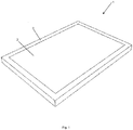
- Fig. 1 the cooking device 1 according to the invention is shown in the idle state.
- the cooking device 1 is embedded in a worktop, not shown. From above - so for the user - are visible the hob 2 and the surrounding the hob 2 frame 3.
- the frame 3 is embedded in the worktop so that it can be subjected to a vertical movement.
- the frame 3 is moved vertically upwards. So will - as in FIG. 2 shown - between the frame 3 and the hob 2, a suction port 4 is released, through which the vapor is sucked by means of the not shown, but arranged under the hob 2 fan device.
- Fig. 3 the cooking device 1 according to the invention shown in more detail. Again, a state of operation is seen.
- the frame 3 is shifted vertically upwards relative to the hob 2.
- On the hob 2 is a saucepan 6. It is at least one intake 4 released.
- a filter element 5 is arranged, with which the extracted cooking fumes 7 are filtered.
- Fig. 4 another embodiment of the invention is shown.
- a frame 3 is arranged, which closes the area between the worktop 8 and hob 2 by means of a cover 9 in the rest position.
- a Wrasenabzugskanal 10 is arranged, can be removed through the vapors during operation of the device.
- the vapor extraction channel 10 is part of the vapor outlet, which is part of the cooking device according to the invention.
- the Wrasenabzugskanal 10 is covered by a filter element 5.
- the cooking fumes are cleaned during fume cupping, for example from fats.
- the frame 3 becomes as in Fig. 5 shown, relative to the hob 2 and thus also relative to the worktop 8 moves vertically. Since the cover 9 remains stationary in the plane of the hob 2, intake openings 4 are released, through which the cooking fumes 7 can be sucked. Before the cooking fumes 7 enter the vapor extraction channel 10, they are filtered by means of a filter element 5.
Landscapes
- Engineering & Computer Science (AREA)
- Chemical & Material Sciences (AREA)
- Combustion & Propulsion (AREA)
- Mechanical Engineering (AREA)
- General Engineering & Computer Science (AREA)
- Ventilation (AREA)
- Combinations Of Kitchen Furniture (AREA)
Abstract
Description
- Die Erfindung betrifft eine Kochvorrichtung, welche insbesondere zur Zubereitung von Speisen vorgesehen ist. Die Kochvorrichtung umfasst ein Kochfeld mit wenigstens einer Kochstelle und umfasst einen Wrasenabzug mit einer Lüftereinrichtung, welche zentrisch unterhalb des Kochfeldes angeordnet ist.
- Das Kochfeld ist in eine Arbeitsplatte eingebaut, die den üblichen Anforderungen, so z.B. einer gewissen Hitzebeständigkeit, entspricht. Es umfasst neben dem zum Garen wichtigen Kochstellen ein Kochstellengehäuse, Kochstellenelektronik und u.U. Bedienelemente. Das Kochfeld weist einen umlaufenden Rahmen auf, der es gegenüber der Arbeitsplatte seitlich abgrenzt. Das Kochfeld ist zudem im Wesentlichen in einer Ebene mit der Arbeitsplatte angeordnet.
- Im Stand der Technik sind derartige Kocheinrichtungen bekannt, die einen Wrasenabzug aufweisen. Einerseits werden Wrasenabzüge häufig oberhalb des Kochfeldes angeordnet, es gibt aber auch Vorrichtungen, die seitlich des Kochfeldes oder vom Benutzer aus gesehen hinter dem Kochfeld angeordnet sind. Diese sind zumeist ausfahrbar oder/oder ausklappbar und saugen die Kochdünste aus einer gewissen Höhe vom Kochfeld ab. Viele Vorrichtungen nach dem Stand der Technik weisen sog. Down-Draft-Systeme auf, bei denen der Wrasenabzug seitlich oder hinter dem Kochfeld angeordnet ist und im Nutzungszustand aus der Arbeitsplatte nach oben heraus gefahren ist. Das Anordnen dieser Systeme bedingt, dass seitlich und hinter dem Kochfeld ausreichend Raum für die Abzüge vorgehalten wird. Bei kleineren Küchen ist eine derartige Anordnung daher nur eingeschränkt möglich. Wenn nicht auf eine Dunstabzugshaube oberhalb des Kochfeldes ausgewichen wird, muss ein kleineres Kochfeld installiert werden. Dies ist vom Kunden oft nicht gewünscht. Außerdem gibt es Kunden, die den zusätzlich zum Kochfeld vorgehaltenen Down-Draft-Dunstabzug aus gestalterischen Gründen ablehnen.
- Um diesen Nachteilen abzuhelfen, sind verschiedene Vorrichtungen offenbart worden. So ist z.B. die Schrift
DE 20 2008 013 350 U1 zu nennen, die ein Vorrichtung zum Kochen beschreibt. Sie ist durch eine Kochfeld-Einheit gekennzeichnet, die mehrere Kochstellen umfasst. Zwischen den Kochstellen, in den rück und/oder frontwärtigen Randbereichen und/oder in den seitlichen Randbereichen sind Einrichtungen zum Absaugen von Kochdünsten angeordnet. Zudem weist die Kochfeld-Einheit aber auch noch mindestens eine Einrichtung zur Zufuhr von Luft als Spülmedium auf. Bei Bedarf werden die einzelnen Kochstellen sogar durch abgedeckte Kanäle voneinander getrennt, die für den Fall der Nutzung geöffnet werden können. Gemäß eines Ausführungsbeispiels kann der Vorrichtung aus einem umlaufenden Kanal frische Luft zugeführt werden, die dann zentral über einen Kanal gemeinsam mit den Kochdünsten abgesaugt wird. Nachteilig ist, dass mit erhöhtem Aufwand eine Zufuhr von Frischluft gewährleistet werden muss. Dies ist auch deshalb nötig, weil ein Absaugen der warmen Kochdünste in die Ebene der Arbeitsplatte nur dann mit messbarem Erfolg erreicht werden kann, wenn die Kochdünste mit Hilfe der Frischluft in einem Bereich der Absaugung geblasen werden. Der erhöhte Aufwand der Vorrichtung spiegelt sich letztendlich auch in einem erhöhten Aufwand bei Installation und Wartung wieder. - Der Erfindung stellt sich somit das Problem, eine Kochvorrichtung bereitzustellen, die über einen Wrasenabzug verfügt, welcher die Nachteile des Standes der Technik beseitigt.
- Erfindungsgemäß wird dieses Problem durch eine Kochvorrichtung mit den Merkmalen des Patentanspruchs 1 gelöst. Vorteilhafte Ausgestaltungen und Weiterbildungen der Erfindung ergeben sich aus der allgemeinen Beschreibung und aus den nachfolgenden Unteransprüchen.
- Dabei umfasst die Kochvorrichtung ein Kochfeld, einen Wrasenabzug und einen um das Kochfeld umlaufenden Rahmen. Der Wrasenabzug weist eine Lüftereinrichtung auf, die in Einbaulage der Kochvorrichtung unterhalb des Kochfeldes angeordnet ist. Die Kochvorrichtung ist im Wesentlichen in einer Ebene mit einer Arbeitsplatte angeordnet. Sie ist dadurch gekennzeichnet, dass der Rahmen zumindest abschnittsweise gegenüber dem Kochfeld vertikal bewegbar angeordnet ist. In einem Ruhezustand befindet es sich dabei in einer Ebene mit dem Kochfeld. Sobald der Betrieb des Kochfeldes oder insbesondere auch des Wrasenabzuges aufgenommen werden soll oder aufgenommen worden ist, also in einem Betriebszustand, befindet sich dieser Rahmen zumindest abschnittsweise gegenüber dem Kochfeld erhöht. Dabei wird mindestens eine Ansaugöffnung des Wrasenabzuges freigegeben. Optisch ist der Rahmen im Ruhezustand ein Teil des Kochfeldes, der das Kochfeld gegenüber der Arbeitsplatte abgrenzt. Dieses kommt dem Verbraucher, der Wert auf eine dezente Anordnung von Kücheneinrichtungen legt, entgegen, ohne dass auf den Wrasenabzug verzichtet werden muss. Vor der Betriebsaufnahme oder während des Betriebes des Kochfeldes, spätestens aber vor Inbetriebnahme des Wrasenabzuges wird der Rahmen gegenüber der Ebene der Arbeitsplatte vertikal nach oben verschoben, so dass die Ansaugöffnung des Wrasenabzuges freigegeben wird. Kochdünste können so aus dem Bereich des Kochfeldes abgesogen werden. Nach dem Verschließen der Absaugöffnung bilden Arbeitsplatte, Rahmen und Kochfeld nahezu eine Ebene, so dass der anfängliche optische Eindruck wieder erreicht wird. Eine vollständige vertikale Bewegung des Rahmens ist vorzuziehen, weil die dafür benötigten Mittel in geringerer Zahl in der Vorrichtung vorgehalten werden müssen. Allerdings ist durchaus denkbar, dass der Rahmen abschnittsweise vom Ruhezustand in den Betriebszustand überführt wird, z.B. in Abhängigkeit von der zum Kochen benutzten Kochstelle.
- In einer besonders bevorzugten Ausgestaltung der erfindungsgemäßen Kochvorrichtung ist die Ansaugöffnung des Wrasenabzuges im Betriebszustand des Wrasenabzuges umlaufend um das Kochfeld angeordnet. So kann unabhängig von der Nutzung des Kochfeldes ein optimaler Abzug des Wrasen gewährleistet werden, auch wenn man das Kochgeschirr während des Kochvorganges von einer Kochstelle auf eine andere Kochstelle des selben Kochfeldes verschiebt.
- Darüber hinaus in einer besonders bevorzugten Ausgestaltung der erfindungsgemäßen Kochvorrichtung in der Ansaugöffnung mindestens ein Filterelement angeordnet. Die vom Kochfeld aufsteigenden Kochdünste sollten vor dem Ableiten nach Außen oder zurück in die Küche einer Reinigung unterzogen werden, um z.B. Fette aus den Kochdünsten zu entnehmen. Um ein u.U. unterhalb des Kochfeldes angeordnetes und damit aufwändig zu reinigendes Filterelement zu vermeiden, ist dieses in der Ansaugöffnung platziert. Zur Entnahme des Filterelements kann der Rahmen durchaus auch höher aus der Arbeitsplatte herausfahren, als es während des Betriebes des Kochfeldes der Fall ist, um eine leichte Entnahme des Filterelements zu ermöglichen. Es können aber auch im Rahmeninneren Mechanismen vorgesehen sein, die ein Lösen des Filterelements aus dem Rahmen ermöglichen oder erleichtern. Es kann auch vorgesehen sein, dass zur leichteren Entnahme des Filterelements daran befestigte Abdeckungen, die im Ruhezustand des Rahmens mit dem Rahmen und dem Kochfeld im Wesentlichen in einer Ebene angeordnet sind, zur gemeinsamen Entnahme mit dem Filterelements dienen. Dies erleichtert die Handhabung.
- In einer weiteren besonders bevorzugten Ausführung der erfindungsgemäßen Kochvorrichtung ist das Filterelement beim Verfahren des Rahmens aus dem Ruhezustand in den Betriebszustand aus einer Ruheposition in eine Arbeitsposition verfahrbar. Die einfachste Möglichkeit hier ist eine feste Position des Filterelements innerhalb des Rahmens, so dass das Filterelement beim Aktivieren des Wrasenabzuges gemeinsam mit dem Rahmen in eine Position des Betriebszustandes verfahren wird. Das Filterelement ist dabei mit einer Längsseite im Rahmeninneren lösbar befestigt. Filterelement und Rahmen bilden dann eine weitestgehend starre Einheit. Zwischen Unterkante des Filterelements und dem Kochfeld kann dann ein abzudichtender Spalt entstehen. Um die Filterfläche zu vergrößern und gleichzeitig einen Spalt zu vermeiden, kann es aber auch vorgesehen sein, dass das Filterelement im Rahmen entlang einer Längsseite parallel zum Kochfeld gelagert ist und mit der anderen Längsseite entweder auf Grund einer Vorspannung oder durch eine Führung in Schienen einen Abschluss mit dem Kochfeld bildet. Der Reinigungserfolg des Filterelements wird dadurch erhöht. Um einem geringeren Raumbedarf gerecht zu werden, kann es auch vorgesehen sein, dass das Filterelement im Ruhezustand weitestgehend senkrecht zum Kochfeld in einer Filterelementaufnahme platziert ist und nach dem Einschalten des Wrasenabzugs bzw. nach dem Verfahren des Rahmens in den Betriebszustand automatisch in eine Betriebsposition geklappt wird, die ein optimales Reinigen der Kochdünste gewährleistet.
- In einer weiteren besonders bevorzugten Ausgestaltung der erfindungsgemäßen Kochvorrichtung ist der Rahmen maximal um die Höhe des Kochfeldes vertikal verfahrbar. Das Kochfeld sollte - gerade im Hinblick auf einen nur unwesentlich gegenüber einer Kochvorrichtung nach dem Stand der Technik vergrößerten Platzbedarf - durch den Rahmen eine nicht wesentlich größere Einbauhöhe haben. Ein Rahmen mit starren Seiten ist einfach zu produzieren. Um die Einbauhöhe nicht zu stark zu überschreiten, sollte der über das Kochfeld hinaus stehende Rahmen also nicht weiter über das Kochfeld hinaus stehen, als das Kochfeld selbst hoch ist.
- In einer bevorzugten Ausgestaltung der erfindungsgemäßen Kochvorrichtung ist der Rahmen manuell verfahrbar. Der Nutzer kann so durch manuelles Betätigen den Rahmen aus dem Ruhezustand in den Betriebszustand überführen. Dies kann einerseits mechanisch erfolgen. So führt z.B. das Betätigen eines Knopfes zur Entriegelung eines Riegels, welcher den Rahmen im Ruhezustand hält. Auch ein sog. Push-To-Open-Mechanismus ist denkbar, bei dem durch Drücken auf den Rahmen ein Schließmechanismus überwunden und der Rahmen mittels Federkraft geöffnet wird. Ein Drücken des Rahmens in seinen Ruhezustand gegen den Widerstand der Feder aktiviert diesen Schließmechanismus wieder. Nach dem Öffnen kann der Wrasenabzug gestartet werden, es kann aber auch vorgesehen sein, dass mit dem Öffnen des Rahmens automatisch der Wrasenabzug seine Arbeit aufnimmt. Gleiches gilt beim Abschalten, so dass mit der Aufnahme des Schließvorganges automatisch umgehend der Wrasenabzug abgeschaltet wird.
- In einer weiteren bevorzugten Ausgestaltung der erfindungsgemäßen Kochvorrichtung ist der Rahmen motorisch verfahrbar. Hier liegt der Fokus in der besonderen Bedienerfreundlichkeit der Kochvorrichtung. Durch Betätigen eines Bedienungselements wird der Rahmen von der Ruheposition in die Betriebsposition motorisch verfahren. Die hierdurch gewährleistete Gleichmäßigkeit des Ausfahrens wirkt sich auch schonen auf die anderen Bauteile, z.B. auf die Filterelemente aus.
- Nach einer weiteren bevorzugten Ausführungsform der erfindungsgemäßen Kochvorrichtung verfährt der Rahmen beim Einschalten des Kochfeldes und/oder beim Einschalten des Wrasenabzuges automatisch aus dem Ruhezustand in den Betriebszustand. Durch die Verknüpfung der beiden Vorgänge wird nicht nur eine Vereinfachung für den Nutzer und eine Bedienkomfort herbeigeführt, insbesondere wird eine optimale Abstimmung zwischen der Aktivierung des Wrasenabzuges und dem Öffnen des Rahmens erreicht, um den Wrasenabzug z.B. vor Beschädigungen durch zu frühes Ansaugen zu schützen bzw. bei Beginn des Kochvorganges sofort einen optimalen Abzug von Kochdünsten zu erreichen.
- Die mit der Erfindung erreichbaren Vorteile bestehen im Wesentlichen in dem sehr platzsparenden Aufbau der Vorrichtung. Auch auf kleinstem Raum kann ein Wrasenabzug bereit gestellt werden, der jedoch im Ruhezustand optisch nicht wahrnehmbar ist. Dabei geht der Bedienungskomfort für den Nutzer nicht verloren. Trotzdem werden Kochdünste durch den gegenüber dem Kochfeld erhöht angeordneten Wrasenabzug gut abgenommen und der Filterung unterzogen.
- Zwei Ausführungsbeispiele der Erfindung sind in den Zeichnungen rein schematisch dargestellt und wird nachfolgend näher beschrieben. Es zeigen
- Figur 1
- die erfindungsgemäße Kochvorrichtung in einer ersten Ausführungsform in einem Ruhezustand,
- Figur 2
- die erfindungsgemäße Kochvorrichtung in einer ersten Ausführungsform in einem Betriebszustand,
- Figur 3
- einen Schnitt durch die erfindungsgemäße Kochvorrichtung der ersten Ausführungsform,
- Figur 4
- einen Schnitt durch die erfindungsgemäße Kochvorrichtung der zweiten Ausführungsform in einem Ruhezustand und
- Figur 5
- einen Schnitt durch die erfindungsgemäße Kochvorrichtung der zweiten Ausführungsform in einem Betriebszustand.
- In
Fig. 1 ist die erfindungsgemäße Kochvorrichtung 1 im Ruhezustand dargestellt. Die Kochvorrichtung 1 ist in eine nicht dargestellte Arbeitsplatte eingelassen. Von oben - also für den Nutzer - sichtbar sind das Kochfeld 2 und der das Kochfeld 2 umgebende Rahmen 3. Der Rahmen 3 ist derart in die Arbeitsplatte eingelassen, dass er einer vertikalen Bewegung unterzogen werden kann. - Sobald der Betrieb der Kochvorrichtung 1 aufgenommen werden soll oder aufgenommen ist, jedenfalls vor Inbetriebnahme der Wrasenabzugseinrichtung wird der Rahmen 3 vertikal nach oben verfahren. So wird - wie in
Figur 2 dargestellt - zwischen dem Rahmen 3 und dem Kochfeld 2 eine Ansaugöffnung 4 freigegeben, durch die der Wrasen mittels der nicht dargestellten aber unter dem Kochfeld 2 angeordneten Lüftereinrichtung abgesaug wird. - In einem Schnitt wird in
Fig. 3 die erfindungsgemäße Kochvorrichtung 1 genauer gezeigt. Auch hier ist ein Betriebszustand zu sehen. Der Rahmen 3 ist gegenüber dem Kochfeld 2 vertikal nach oben verschoben. Auf dem Kochfeld 2 steht ein Kochtopf 6. Es ist wenigstens eine Ansaugöffnung 4 freigegeben. In der Ansaugöffnung 4 ist ein Filterelement 5 angeordnet, mit dem die abgesaugten Kochdünste 7 gefiltert werden. - In
Fig. 4 ist eine andere Ausführungsform der Erfindung dargestellt. Hier ist zwischen Arbeitsplatte 8 und Kochfeld 2 ein Rahmen 3 angeordnet, der mittels einer Abdeckung 9 in der Ruhestellung den Bereich zwischen Arbeitsplatte 8 und Kochfeld 2 verschließt. Unterhalb der Abdeckung 9 ist ein Wrasenabzugskanal 10 angeordnet, durch den Wrasen bei Betrieb der Vorrichtung abgeführt werden kann. Der Wrasenabzugskanal 10 ist Teil des Wrasenabzugs, der Teil der erfindungsgemäßen Kochvorrichtung ist. Der Wrasenabzugskanal 10 ist dabei von einem Filterelement 5 abgedeckt. So werden die Kochdünste beim Abzug z.B. von Fetten gereinigt. - Sobald die Vorrichtung in eine Betriebsstellung übergeht, wird der Rahmen 3 wie in
Fig. 5 dargestellt, relativ gegenüber dem Kochfeld 2 und damit auch gegenüber der Arbeitsplatte 8 vertikal bewegt. Da die Abdeckung 9 dabei ortsfest in der Ebene des Kochfeldes 2 verbleibt, werden Ansaugöffnungen 4 freigegeben, durch die die Kochdünste 7 abgesaugt werden können. Bevor die Kochdünste 7 in den Wrasenabzugskanal 10 eintreten, werden sie mittels eines Filterelements 5 gefiltert. - Da es sich bei der vorhergehenden, detailliert beschriebenen Kochvorrichtung um ein Ausführungsbeispiel handelt, kann sie in üblicher Weise vom Fachmann in einem weiten Umfang modifiziert werden, ohne den Bereich der Erfindung zu verlassen. Insbesondere können auch die konkreten Ausgestaltungen des Kanalsystems in anderer Form als in der hier beschriebenen folgen. Ebenso kann die Wrasenabzugseinrichtung in einer anderen Form ausgestaltet werden, wenn dies aus Platzgründen bzw. designerischen Gründen notwendig ist. Weiter schließt die Verwendung der unbestimmten Artikel "ein" bzw. "eine" nicht aus, dass die betreffenden Merkmale auch mehrfach vorhanden sein können.
-
- 1
- Kochvorrichtung
- 2
- Kochfeld
- 3
- Rahmen
- 4
- Ansaugöffnung
- 5
- Filterelement
- 6
- Kochtopf
- 7
- Kochdünste
- 8
- Arbeitsplatte
- 9
- Abdeckung
- 10
- Wrasenabzugskanal
Claims (8)
- Kochvorrichtung (1), umfassend ein Kochfeld (2), einen Wrasenabzug mit einer in Einbaulage der Kochvorrichtung (1) unterhalb des Kochfeldes (2) angeordneten Lüftereinrichtung und einen um das Kochfeld (2) umlaufenden Rahmen (3), wobei die Kochvorrichtung (1) im Wesentlichen in einer Ebene mit einer Arbeitsplatte angeordnet ist, dadurch gekennzeichnet, dass der Rahmen (3) zumindest abschnittsweise relativ gegenüber dem Kochfeld (2) vertikal bewegbar angeordnet ist und sich in einem Ruhezustand in einer Ebene mit dem Kochfeld (2) und in einem Betriebszustand, insbesondere des Wrasenabzuges, zumindest abschnittsweise gegenüber dem Kochfeld (2) erhöht befindet, und im Betriebszustand mindestens eine Ansaugöffnung (4) des Wrasenabzuges freigibt.
- Kochvorrichtung (1) nach Anspruch 1, dadurch gekennzeichnet, dass die Ansaugöffnung (4) des Wrasenabzuges im Betriebszustand des Wrasenabzuges umlaufend um das Kochfeld (2) angeordnet ist.
- Kochvorrichtung (1) nach einem der vorhergehenden Ansprüche, dadurch gekennzeichnet, dass in der Ansaugöffnung (4) mindestens ein Filterelement (5) angeordnet ist.
- Kochvorrichtung (1) nach Anspruch 3, dadurch gekennzeichnet, dass das Filterelement (5) beim Verfahren des Rahmens (3) aus dem Ruhezustand in den Betriebszustand aus einer Ruheposition in eine Arbeitsposition verfahrbar ist.
- Kochvorrichtung (1) nach einem der vorhergehenden Ansprüche, dadurch gekennzeichnet, dass der Rahmen (3) maximal um die Höhe der Kochvorrichtung (1), vorzugsweise maximal um die die Höhe des Kochfeldes (2) vertikal verfahrbar ist.
- Kochvorrichtung (1) nach einem der vorhergehenden Ansprüche, dadurch gekennzeichnet, dass der Rahmen (3) manuell verfahrbar ist.
- Kochvorrichtung (1) nach einem der vorhergehenden Ansprüche, dadurch gekennzeichnet, dass der Rahmen (3) motorisch verfahrbar ist.
- Kochvorrichtung (1) nach Anspruch 7, dadurch gekennzeichnet, dass der Rahmen (3) beim Einschalten des Kochfeldes (2) und/oder beim Einschalten des Wrasenabzuges automatisch aus dem Ruhezustand in den Betriebszustand verfährt.
Applications Claiming Priority (1)
| Application Number | Priority Date | Filing Date | Title |
|---|---|---|---|
| DE102015119310.8A DE102015119310A1 (de) | 2015-11-10 | 2015-11-10 | Kochvorrichtung |
Publications (2)
| Publication Number | Publication Date |
|---|---|
| EP3168537A1 true EP3168537A1 (de) | 2017-05-17 |
| EP3168537B1 EP3168537B1 (de) | 2020-04-22 |
Family
ID=57206164
Family Applications (1)
| Application Number | Title | Priority Date | Filing Date |
|---|---|---|---|
| EP16195792.3A Active EP3168537B1 (de) | 2015-11-10 | 2016-10-26 | Kochvorrichtung mit dunstabzugsvorrichtung |
Country Status (3)
| Country | Link |
|---|---|
| EP (1) | EP3168537B1 (de) |
| DE (1) | DE102015119310A1 (de) |
| ES (1) | ES2791192T3 (de) |
Cited By (5)
| Publication number | Priority date | Publication date | Assignee | Title |
|---|---|---|---|---|
| EP3441681A1 (de) * | 2017-08-09 | 2019-02-13 | Miele & Cie. KG | Kochvorrichtung |
| DE102017120193A1 (de) | 2017-09-01 | 2019-03-07 | minEnergy GmbH | Kochelement |
| DE102017129011A1 (de) * | 2017-12-06 | 2019-06-06 | Miele & Cie. Kg | Kochvorrichtung |
| IT201800006807A1 (it) * | 2018-06-29 | 2019-12-29 | Gruppo piano cottura e cappa. | |
| TWI833858B (zh) * | 2019-12-16 | 2024-03-01 | 義大利商B S 服務有限公司 | 爐架及抽油煙機總成 |
Families Citing this family (4)
| Publication number | Priority date | Publication date | Assignee | Title |
|---|---|---|---|---|
| CN107300199B (zh) * | 2017-07-20 | 2023-05-05 | 杭州老板电器股份有限公司 | 一种立体进风油烟机 |
| DE102017128992A1 (de) * | 2017-12-06 | 2019-06-06 | Miele & Cie. Kg | Kochvorrichtung |
| DE102018107904B4 (de) | 2018-04-04 | 2024-05-16 | Miele & Cie. Kg | Luftabzugsvorrichtung für ein Kochfeld |
| DE102018130828A1 (de) * | 2018-12-04 | 2020-06-04 | Miele & Cie. Kg | Dunstabzug |
Citations (6)
| Publication number | Priority date | Publication date | Assignee | Title |
|---|---|---|---|---|
| US3303839A (en) * | 1965-06-01 | 1967-02-14 | Tavan Louis | Ventilated cooking stove unit |
| DE2749824A1 (de) * | 1976-11-11 | 1978-05-18 | Kemtron Properties Pty Ltd | Abzugshaube |
| DE68903757T2 (de) * | 1988-01-14 | 1993-05-13 | Yano Corp | Kochgeraet mit entlueftungsvorrichtung. |
| DE202008013350U1 (de) | 2008-10-11 | 2009-01-08 | Bruckbauer, Wilhelm | Vorrichtung zum Kochen mit Spül-Luftzuführung und Spül-Luftabsaugung |
| DE102010042436A1 (de) * | 2010-10-14 | 2012-04-19 | BSH Bosch und Siemens Hausgeräte GmbH | Kochfeld mit integrierter Dunsthaube |
| DE102015104470A1 (de) * | 2015-03-25 | 2016-09-29 | Miele & Cie. Kg | Kochfeld sowie ein Verfahren zum Betreiben eines Kochfeldes |
-
2015
- 2015-11-10 DE DE102015119310.8A patent/DE102015119310A1/de not_active Withdrawn
-
2016
- 2016-10-26 EP EP16195792.3A patent/EP3168537B1/de active Active
- 2016-10-26 ES ES16195792T patent/ES2791192T3/es active Active
Patent Citations (6)
| Publication number | Priority date | Publication date | Assignee | Title |
|---|---|---|---|---|
| US3303839A (en) * | 1965-06-01 | 1967-02-14 | Tavan Louis | Ventilated cooking stove unit |
| DE2749824A1 (de) * | 1976-11-11 | 1978-05-18 | Kemtron Properties Pty Ltd | Abzugshaube |
| DE68903757T2 (de) * | 1988-01-14 | 1993-05-13 | Yano Corp | Kochgeraet mit entlueftungsvorrichtung. |
| DE202008013350U1 (de) | 2008-10-11 | 2009-01-08 | Bruckbauer, Wilhelm | Vorrichtung zum Kochen mit Spül-Luftzuführung und Spül-Luftabsaugung |
| DE102010042436A1 (de) * | 2010-10-14 | 2012-04-19 | BSH Bosch und Siemens Hausgeräte GmbH | Kochfeld mit integrierter Dunsthaube |
| DE102015104470A1 (de) * | 2015-03-25 | 2016-09-29 | Miele & Cie. Kg | Kochfeld sowie ein Verfahren zum Betreiben eines Kochfeldes |
Cited By (7)
| Publication number | Priority date | Publication date | Assignee | Title |
|---|---|---|---|---|
| EP3441681A1 (de) * | 2017-08-09 | 2019-02-13 | Miele & Cie. KG | Kochvorrichtung |
| DE102017120193A1 (de) | 2017-09-01 | 2019-03-07 | minEnergy GmbH | Kochelement |
| DE102017120193B4 (de) | 2017-09-01 | 2021-11-25 | aptus 1752. GmbH | Kochelement |
| DE102017129011A1 (de) * | 2017-12-06 | 2019-06-06 | Miele & Cie. Kg | Kochvorrichtung |
| IT201800006807A1 (it) * | 2018-06-29 | 2019-12-29 | Gruppo piano cottura e cappa. | |
| WO2020002456A1 (en) * | 2018-06-29 | 2020-01-02 | B.S. Service S.R.L. | Hob-extractor hood assembly |
| TWI833858B (zh) * | 2019-12-16 | 2024-03-01 | 義大利商B S 服務有限公司 | 爐架及抽油煙機總成 |
Also Published As
| Publication number | Publication date |
|---|---|
| EP3168537B1 (de) | 2020-04-22 |
| DE102015119310A1 (de) | 2017-05-11 |
| ES2791192T3 (es) | 2020-11-03 |
Similar Documents
| Publication | Publication Date | Title |
|---|---|---|
| EP3168537B1 (de) | Kochvorrichtung mit dunstabzugsvorrichtung | |
| EP3953645B1 (de) | Vorrichtung zum erhitzen von gargut | |
| DE2756428C2 (de) | ||
| EP3502571B1 (de) | Dunstabzugsvorrichtung, küchengerät mit kochfeld und dunstabzugsvorrichtung und verfahren zum betreiben einer dunstabzugsvorrichtung | |
| DE102015104470B4 (de) | Kochfeld sowie ein Verfahren zum Betreiben eines Kochfeldes | |
| DE102018130828A1 (de) | Dunstabzug | |
| DE102018215480A1 (de) | Dunstabzugsvorrichtung mit Verschlussklappe | |
| EP2623869A1 (de) | Dunstabzugshaube | |
| EP3502572B1 (de) | Dunstabzugsvorrichtung, küchengerät mit kochfeld und dunstabzugsvorrichtung und verfahren zum betreiben einer dunstabzugsvorrichtung | |
| DE102015111337B4 (de) | Kochvorrichtung | |
| EP3299725B1 (de) | Dunstabzugsvorrichtung mit abdeckung für eine gehäuseöffnung des dunstabzugsgehäuses der dunstabzugsvorrichtung | |
| EP2554917B1 (de) | Vorrichtung zur Absaugung von Luft bei einem Kochfeld | |
| DE2914862C2 (de) | Dunstabzugshaube zur Anordnung über einem Küchenherd od. dgl. | |
| EP2772695A2 (de) | Dunstabzugshaube | |
| EP1120607B1 (de) | Vorrichtung für einen mit einer Ofentür versehenen Erhitzungsofen | |
| DE102013213185A1 (de) | Unterbauhaube und Küchenschrank mit Unterbauhaube | |
| EP2145134A1 (de) | Dunstabzugsvorrichtung | |
| EP3301375A1 (de) | Abdeckvorrichtung für einen muldenlüfter und muldenlüftereinlasseinheit mit einer abdeckvorrichtung | |
| DE102015119322A1 (de) | Vorrichtung zur Absaugung von Kochdünsten | |
| EP3348913B1 (de) | Dunstabzugshaube und Verfahren zum Betreiben | |
| DE102015100745A1 (de) | Absaugvorrichtung und Verfahren zum Betreiben | |
| BE1030368B1 (de) | Dunstabzug | |
| EP2944883A1 (de) | Dunstabzugshaubeneinrichtung und verfahren | |
| EP3425282A1 (de) | Kombinationsgerät mit kochfeld und in dem kochfeld integrierter dunstabzugsvorrichtung | |
| BE1029411B1 (de) | Flachpaneelhaube |
Legal Events
| Date | Code | Title | Description |
|---|---|---|---|
| PUAI | Public reference made under article 153(3) epc to a published international application that has entered the european phase |
Free format text: ORIGINAL CODE: 0009012 |
|
| STAA | Information on the status of an ep patent application or granted ep patent |
Free format text: STATUS: REQUEST FOR EXAMINATION WAS MADE |
|
| 17P | Request for examination filed |
Effective date: 20170315 |
|
| AK | Designated contracting states |
Kind code of ref document: A1 Designated state(s): AL AT BE BG CH CY CZ DE DK EE ES FI FR GB GR HR HU IE IS IT LI LT LU LV MC MK MT NL NO PL PT RO RS SE SI SK SM TR |
|
| AX | Request for extension of the european patent |
Extension state: BA ME |
|
| STAA | Information on the status of an ep patent application or granted ep patent |
Free format text: STATUS: EXAMINATION IS IN PROGRESS |
|
| 17Q | First examination report despatched |
Effective date: 20170919 |
|
| GRAP | Despatch of communication of intention to grant a patent |
Free format text: ORIGINAL CODE: EPIDOSNIGR1 |
|
| STAA | Information on the status of an ep patent application or granted ep patent |
Free format text: STATUS: GRANT OF PATENT IS INTENDED |
|
| INTG | Intention to grant announced |
Effective date: 20191220 |
|
| GRAS | Grant fee paid |
Free format text: ORIGINAL CODE: EPIDOSNIGR3 |
|
| GRAA | (expected) grant |
Free format text: ORIGINAL CODE: 0009210 |
|
| STAA | Information on the status of an ep patent application or granted ep patent |
Free format text: STATUS: THE PATENT HAS BEEN GRANTED |
|
| AK | Designated contracting states |
Kind code of ref document: B1 Designated state(s): AL AT BE BG CH CY CZ DE DK EE ES FI FR GB GR HR HU IE IS IT LI LT LU LV MC MK MT NL NO PL PT RO RS SE SI SK SM TR |
|
| REG | Reference to a national code |
Ref country code: CH Ref legal event code: EP |
|
| REG | Reference to a national code |
Ref country code: DE Ref legal event code: R096 Ref document number: 502016009631 Country of ref document: DE |
|
| REG | Reference to a national code |
Ref country code: IE Ref legal event code: FG4D Free format text: LANGUAGE OF EP DOCUMENT: GERMAN |
|
| REG | Reference to a national code |
Ref country code: AT Ref legal event code: REF Ref document number: 1260621 Country of ref document: AT Kind code of ref document: T Effective date: 20200515 |
|
| REG | Reference to a national code |
Ref country code: DE Ref legal event code: R084 Ref document number: 502016009631 Country of ref document: DE |
|
| REG | Reference to a national code |
Ref country code: LT Ref legal event code: MG4D |
|
| REG | Reference to a national code |
Ref country code: NL Ref legal event code: MP Effective date: 20200422 |
|
| PG25 | Lapsed in a contracting state [announced via postgrant information from national office to epo] |
Ref country code: LT Free format text: LAPSE BECAUSE OF FAILURE TO SUBMIT A TRANSLATION OF THE DESCRIPTION OR TO PAY THE FEE WITHIN THE PRESCRIBED TIME-LIMIT Effective date: 20200422 Ref country code: NO Free format text: LAPSE BECAUSE OF FAILURE TO SUBMIT A TRANSLATION OF THE DESCRIPTION OR TO PAY THE FEE WITHIN THE PRESCRIBED TIME-LIMIT Effective date: 20200722 Ref country code: NL Free format text: LAPSE BECAUSE OF FAILURE TO SUBMIT A TRANSLATION OF THE DESCRIPTION OR TO PAY THE FEE WITHIN THE PRESCRIBED TIME-LIMIT Effective date: 20200422 Ref country code: SE Free format text: LAPSE BECAUSE OF FAILURE TO SUBMIT A TRANSLATION OF THE DESCRIPTION OR TO PAY THE FEE WITHIN THE PRESCRIBED TIME-LIMIT Effective date: 20200422 Ref country code: PT Free format text: LAPSE BECAUSE OF FAILURE TO SUBMIT A TRANSLATION OF THE DESCRIPTION OR TO PAY THE FEE WITHIN THE PRESCRIBED TIME-LIMIT Effective date: 20200824 Ref country code: GR Free format text: LAPSE BECAUSE OF FAILURE TO SUBMIT A TRANSLATION OF THE DESCRIPTION OR TO PAY THE FEE WITHIN THE PRESCRIBED TIME-LIMIT Effective date: 20200723 Ref country code: IS Free format text: LAPSE BECAUSE OF FAILURE TO SUBMIT A TRANSLATION OF THE DESCRIPTION OR TO PAY THE FEE WITHIN THE PRESCRIBED TIME-LIMIT Effective date: 20200822 Ref country code: FI Free format text: LAPSE BECAUSE OF FAILURE TO SUBMIT A TRANSLATION OF THE DESCRIPTION OR TO PAY THE FEE WITHIN THE PRESCRIBED TIME-LIMIT Effective date: 20200422 |
|
| REG | Reference to a national code |
Ref country code: ES Ref legal event code: FG2A Ref document number: 2791192 Country of ref document: ES Kind code of ref document: T3 Effective date: 20201103 |
|
| PG25 | Lapsed in a contracting state [announced via postgrant information from national office to epo] |
Ref country code: RS Free format text: LAPSE BECAUSE OF FAILURE TO SUBMIT A TRANSLATION OF THE DESCRIPTION OR TO PAY THE FEE WITHIN THE PRESCRIBED TIME-LIMIT Effective date: 20200422 Ref country code: HR Free format text: LAPSE BECAUSE OF FAILURE TO SUBMIT A TRANSLATION OF THE DESCRIPTION OR TO PAY THE FEE WITHIN THE PRESCRIBED TIME-LIMIT Effective date: 20200422 Ref country code: LV Free format text: LAPSE BECAUSE OF FAILURE TO SUBMIT A TRANSLATION OF THE DESCRIPTION OR TO PAY THE FEE WITHIN THE PRESCRIBED TIME-LIMIT Effective date: 20200422 Ref country code: BG Free format text: LAPSE BECAUSE OF FAILURE TO SUBMIT A TRANSLATION OF THE DESCRIPTION OR TO PAY THE FEE WITHIN THE PRESCRIBED TIME-LIMIT Effective date: 20200722 |
|
| PG25 | Lapsed in a contracting state [announced via postgrant information from national office to epo] |
Ref country code: AL Free format text: LAPSE BECAUSE OF FAILURE TO SUBMIT A TRANSLATION OF THE DESCRIPTION OR TO PAY THE FEE WITHIN THE PRESCRIBED TIME-LIMIT Effective date: 20200422 |
|
| REG | Reference to a national code |
Ref country code: DE Ref legal event code: R097 Ref document number: 502016009631 Country of ref document: DE |
|
| PG25 | Lapsed in a contracting state [announced via postgrant information from national office to epo] |
Ref country code: RO Free format text: LAPSE BECAUSE OF FAILURE TO SUBMIT A TRANSLATION OF THE DESCRIPTION OR TO PAY THE FEE WITHIN THE PRESCRIBED TIME-LIMIT Effective date: 20200422 Ref country code: CZ Free format text: LAPSE BECAUSE OF FAILURE TO SUBMIT A TRANSLATION OF THE DESCRIPTION OR TO PAY THE FEE WITHIN THE PRESCRIBED TIME-LIMIT Effective date: 20200422 Ref country code: EE Free format text: LAPSE BECAUSE OF FAILURE TO SUBMIT A TRANSLATION OF THE DESCRIPTION OR TO PAY THE FEE WITHIN THE PRESCRIBED TIME-LIMIT Effective date: 20200422 Ref country code: DK Free format text: LAPSE BECAUSE OF FAILURE TO SUBMIT A TRANSLATION OF THE DESCRIPTION OR TO PAY THE FEE WITHIN THE PRESCRIBED TIME-LIMIT Effective date: 20200422 Ref country code: SM Free format text: LAPSE BECAUSE OF FAILURE TO SUBMIT A TRANSLATION OF THE DESCRIPTION OR TO PAY THE FEE WITHIN THE PRESCRIBED TIME-LIMIT Effective date: 20200422 |
|
| PG25 | Lapsed in a contracting state [announced via postgrant information from national office to epo] |
Ref country code: PL Free format text: LAPSE BECAUSE OF FAILURE TO SUBMIT A TRANSLATION OF THE DESCRIPTION OR TO PAY THE FEE WITHIN THE PRESCRIBED TIME-LIMIT Effective date: 20200422 Ref country code: SK Free format text: LAPSE BECAUSE OF FAILURE TO SUBMIT A TRANSLATION OF THE DESCRIPTION OR TO PAY THE FEE WITHIN THE PRESCRIBED TIME-LIMIT Effective date: 20200422 |
|
| PLBE | No opposition filed within time limit |
Free format text: ORIGINAL CODE: 0009261 |
|
| STAA | Information on the status of an ep patent application or granted ep patent |
Free format text: STATUS: NO OPPOSITION FILED WITHIN TIME LIMIT |
|
| 26N | No opposition filed |
Effective date: 20210125 |
|
| PG25 | Lapsed in a contracting state [announced via postgrant information from national office to epo] |
Ref country code: SI Free format text: LAPSE BECAUSE OF FAILURE TO SUBMIT A TRANSLATION OF THE DESCRIPTION OR TO PAY THE FEE WITHIN THE PRESCRIBED TIME-LIMIT Effective date: 20200422 |
|
| REG | Reference to a national code |
Ref country code: CH Ref legal event code: PL |
|
| PG25 | Lapsed in a contracting state [announced via postgrant information from national office to epo] |
Ref country code: MC Free format text: LAPSE BECAUSE OF FAILURE TO SUBMIT A TRANSLATION OF THE DESCRIPTION OR TO PAY THE FEE WITHIN THE PRESCRIBED TIME-LIMIT Effective date: 20200422 Ref country code: LU Free format text: LAPSE BECAUSE OF NON-PAYMENT OF DUE FEES Effective date: 20201026 |
|
| REG | Reference to a national code |
Ref country code: BE Ref legal event code: MM Effective date: 20201031 |
|
| PG25 | Lapsed in a contracting state [announced via postgrant information from national office to epo] |
Ref country code: BE Free format text: LAPSE BECAUSE OF NON-PAYMENT OF DUE FEES Effective date: 20201031 Ref country code: CH Free format text: LAPSE BECAUSE OF NON-PAYMENT OF DUE FEES Effective date: 20201031 Ref country code: LI Free format text: LAPSE BECAUSE OF NON-PAYMENT OF DUE FEES Effective date: 20201031 |
|
| PG25 | Lapsed in a contracting state [announced via postgrant information from national office to epo] |
Ref country code: IE Free format text: LAPSE BECAUSE OF NON-PAYMENT OF DUE FEES Effective date: 20201026 |
|
| PG25 | Lapsed in a contracting state [announced via postgrant information from national office to epo] |
Ref country code: MT Free format text: LAPSE BECAUSE OF FAILURE TO SUBMIT A TRANSLATION OF THE DESCRIPTION OR TO PAY THE FEE WITHIN THE PRESCRIBED TIME-LIMIT Effective date: 20200422 Ref country code: CY Free format text: LAPSE BECAUSE OF FAILURE TO SUBMIT A TRANSLATION OF THE DESCRIPTION OR TO PAY THE FEE WITHIN THE PRESCRIBED TIME-LIMIT Effective date: 20200422 |
|
| PG25 | Lapsed in a contracting state [announced via postgrant information from national office to epo] |
Ref country code: MK Free format text: LAPSE BECAUSE OF FAILURE TO SUBMIT A TRANSLATION OF THE DESCRIPTION OR TO PAY THE FEE WITHIN THE PRESCRIBED TIME-LIMIT Effective date: 20200422 |
|
| REG | Reference to a national code |
Ref country code: AT Ref legal event code: MM01 Ref document number: 1260621 Country of ref document: AT Kind code of ref document: T Effective date: 20211026 |
|
| PG25 | Lapsed in a contracting state [announced via postgrant information from national office to epo] |
Ref country code: AT Free format text: LAPSE BECAUSE OF NON-PAYMENT OF DUE FEES Effective date: 20211026 |
|
| P01 | Opt-out of the competence of the unified patent court (upc) registered |
Effective date: 20230528 |
|
| PGFP | Annual fee paid to national office [announced via postgrant information from national office to epo] |
Ref country code: DE Payment date: 20251031 Year of fee payment: 10 |
|
| PGFP | Annual fee paid to national office [announced via postgrant information from national office to epo] |
Ref country code: GB Payment date: 20251023 Year of fee payment: 10 |
|
| PGFP | Annual fee paid to national office [announced via postgrant information from national office to epo] |
Ref country code: IT Payment date: 20251022 Year of fee payment: 10 |
|
| PGFP | Annual fee paid to national office [announced via postgrant information from national office to epo] |
Ref country code: FR Payment date: 20251027 Year of fee payment: 10 |
|
| PGFP | Annual fee paid to national office [announced via postgrant information from national office to epo] |
Ref country code: TR Payment date: 20251013 Year of fee payment: 10 |
|
| PGFP | Annual fee paid to national office [announced via postgrant information from national office to epo] |
Ref country code: ES Payment date: 20251118 Year of fee payment: 10 |