EP3166552B1 - Vorrichtung und verfahren zum schutz der augen vor strahlung - Google Patents
Vorrichtung und verfahren zum schutz der augen vor strahlung Download PDFInfo
- Publication number
- EP3166552B1 EP3166552B1 EP15744138.7A EP15744138A EP3166552B1 EP 3166552 B1 EP3166552 B1 EP 3166552B1 EP 15744138 A EP15744138 A EP 15744138A EP 3166552 B1 EP3166552 B1 EP 3166552B1
- Authority
- EP
- European Patent Office
- Prior art keywords
- radiation
- sensor arrangement
- closing device
- incident
- incident radiation
- Prior art date
- Legal status (The legal status is an assumption and is not a legal conclusion. Google has not performed a legal analysis and makes no representation as to the accuracy of the status listed.)
- Active
Links
Images


Classifications
-
- G—PHYSICS
- G02—OPTICS
- G02C—SPECTACLES; SUNGLASSES OR GOGGLES INSOFAR AS THEY HAVE THE SAME FEATURES AS SPECTACLES; CONTACT LENSES
- G02C7/00—Optical parts
- G02C7/10—Filters, e.g. for facilitating adaptation of the eyes to the dark; Sunglasses
- G02C7/104—Filters, e.g. for facilitating adaptation of the eyes to the dark; Sunglasses having spectral characteristics for purposes other than sun-protection
-
- A—HUMAN NECESSITIES
- A61—MEDICAL OR VETERINARY SCIENCE; HYGIENE
- A61F—FILTERS IMPLANTABLE INTO BLOOD VESSELS; PROSTHESES; DEVICES PROVIDING PATENCY TO, OR PREVENTING COLLAPSING OF, TUBULAR STRUCTURES OF THE BODY, e.g. STENTS; ORTHOPAEDIC, NURSING OR CONTRACEPTIVE DEVICES; FOMENTATION; TREATMENT OR PROTECTION OF EYES OR EARS; BANDAGES, DRESSINGS OR ABSORBENT PADS; FIRST-AID KITS
- A61F9/00—Methods or devices for treatment of the eyes; Devices for putting in contact-lenses; Devices to correct squinting; Apparatus to guide the blind; Protective devices for the eyes, carried on the body or in the hand
- A61F9/02—Goggles
- A61F9/022—Use of special optical filters, e.g. multiple layers, filters for protection against laser light or light from nuclear explosions, screens with different filter properties on different parts of the screen; Rotating slit-discs
- A61F9/023—Use of special optical filters, e.g. multiple layers, filters for protection against laser light or light from nuclear explosions, screens with different filter properties on different parts of the screen; Rotating slit-discs with variable transmission, e.g. photochromic
-
- A—HUMAN NECESSITIES
- A61—MEDICAL OR VETERINARY SCIENCE; HYGIENE
- A61F—FILTERS IMPLANTABLE INTO BLOOD VESSELS; PROSTHESES; DEVICES PROVIDING PATENCY TO, OR PREVENTING COLLAPSING OF, TUBULAR STRUCTURES OF THE BODY, e.g. STENTS; ORTHOPAEDIC, NURSING OR CONTRACEPTIVE DEVICES; FOMENTATION; TREATMENT OR PROTECTION OF EYES OR EARS; BANDAGES, DRESSINGS OR ABSORBENT PADS; FIRST-AID KITS
- A61F9/00—Methods or devices for treatment of the eyes; Devices for putting in contact-lenses; Devices to correct squinting; Apparatus to guide the blind; Protective devices for the eyes, carried on the body or in the hand
- A61F9/04—Eye-masks ; Devices to be worn on the face, not intended for looking through; Eye-pads for sunbathing
- A61F9/045—Eye-shades or visors; Shields beside, between or below the eyes
-
- G—PHYSICS
- G02—OPTICS
- G02B—OPTICAL ELEMENTS, SYSTEMS OR APPARATUS
- G02B26/00—Optical devices or arrangements for the control of light using movable or deformable optical elements
- G02B26/02—Optical devices or arrangements for the control of light using movable or deformable optical elements for controlling the intensity of light
-
- G—PHYSICS
- G02—OPTICS
- G02C—SPECTACLES; SUNGLASSES OR GOGGLES INSOFAR AS THEY HAVE THE SAME FEATURES AS SPECTACLES; CONTACT LENSES
- G02C7/00—Optical parts
- G02C7/10—Filters, e.g. for facilitating adaptation of the eyes to the dark; Sunglasses
- G02C7/101—Filters, e.g. for facilitating adaptation of the eyes to the dark; Sunglasses having an electro-optical light valve
-
- G—PHYSICS
- G02—OPTICS
- G02C—SPECTACLES; SUNGLASSES OR GOGGLES INSOFAR AS THEY HAVE THE SAME FEATURES AS SPECTACLES; CONTACT LENSES
- G02C7/00—Optical parts
- G02C7/16—Shades; shields; Obturators, e.g. with pinhole, with slot
Definitions
- the invention relates to a device for protecting the eyes from radiation.
- the invention further relates to a method of protecting the eyes from radiation
- the object of the invention is a device and a method for eye protection of persons.
- the dependent claims 2 to 10 relate to further advantageous embodiments.
- the object is further achieved by a method comprising the features of claim 11.
- the dependent claims 12 to 15 relate to further advantageous method steps.
- a device for protecting the eyes from radiation comprising at least two sensor arrangements, an outer sensor arrangement and an inner sensor arrangement, each sensor arrangement having a A plurality of successively arranged beam sensors disposed along each closed loop, and wherein the inner sensor assembly is enclosed by the outer sensor assembly, and wherein the outer and inner sensor assemblies are juxtaposed, and wherein the inner sensor assembly encases a beam passage region, and wherein the beam passage region has a beam passage opening, and wherein a closing device is arranged with respect to the beam passage region such that an incident radiation passing through the beam passage opening either passes through which is completely closed or at least partially attenuated by a tinted surface, and comprising a drive device which is connected to the inner sensor arrangement, the outer sensor arrangement and the closing device.
- each sensor arrangement comprises a plurality of successively arranged beam sensors which are arranged along each of a closed curve, wherein the inner sensor arrangement is enclosed by the outer sensor arrangement, and wherein the inner sensor arrangement encloses a beam passage area, and wherein a beam passage opening in the beam passage area and wherein a closing device is arranged such that an incident radiation passing through the beam passage opening is either transmitted or at least partially attenuated, the closing device being closed when the outer sensor arrangement and subsequently the inner sensor arrangement is irradiated by the incident radiation, or the second sensor arrangement is irradiated and wherein the closing device is reopened when initially the inner sensor arrangement and subsequently only the outer sensor arrangement is irradiated by the incident radiation and wherein both sensor arrangement are ir
- light is meant herein visible light in a wavelength range of 380nm to 780nm.
- Laser beams have a different point size or a different beam diameter depending on the distance of the attack.
- the point size can be about 10m, at 2500m about 2.5m, at, 1250 m have about 1.25m.
- closer distances like 50m about 0.05m and at 25m 0.025m and at a distance of 10m by only 0.01m.
- the inventive device has the advantage that even a small spot size or a small radiation diameter can be safely hidden because the device detects the approach of the beam and the closing device interrupts the beam as soon as it illuminates the outer sensor assembly and subsequently the inner sensor assembly, so the beam no longer falls on the eye. As soon as the jet has returned to the outer sensor arrangement via the inner sensor arrangement and the inner sensor arrangement is no longer illuminated, the closing device can be opened again. In practice, this results in the closing device being closed only for a very short time, so that the pilot's eye is covered only for a very short time, and the pilot has a clear view most of the time without being distracted to become.
- a closing device preferably a mechanical closing device or else an electronic closing device is used, as are known for example from cameras, with shutter speeds of preferably in the range of 10 -3 to 10 -18 seconds.
- the shutter speeds can thus be very short, for example in the range of milliseconds to atto seconds.
- An eye blow lasts about 0.25s.
- the eye is thus too slow to be effectively protected against laser attacks.
- Shuttering time is understood to be the time duration in order to transfer the closing device from the opened state into the closed state.
- the short shutter speed of the device according to the invention thus has the advantage that the eye of the pilot or affected person can be better protected because the eyelid closes only in about 0.25 seconds, especially in laser attacks which are carried out from short and distant distance and have a higher performance.
- the device according to the invention has the particularly advantageous feature that the closure or closing device is preferably opened again immediately, and this preferably even individually, ie, the right and left sides operate autonomously as soon as the laser beam is no longer within the beam passage area that the pilot locomotive driver, bus driver, etc. on the attacked eye very quickly again has a clear view.
- the opening time that is to say the time duration in order to transfer the closing device from the closed state into the opened state, is likewise preferably in the range from 10 -3 to 10 -18 seconds.
- the closing device preferably remains closed until the laser beam is no longer within the beam passage area, in order to be opened immediately thereafter.
- the closing device remains dependent on the irradiation duration during which the beam passage area is irradiated by the laser beam is, closed, the irradiation time depending on the situation may be in the range of fractions of seconds, in unfavorable cases with a longer irradiation time, but also for example in the range of several seconds.
- a separate closure is arranged in front of the left and the right eye, the two closures being controlled independently of one another. This makes it possible for a laser attack with small laser beam sizes that only either the left or the right eye is attacked simultaneously, with the result that usually at least one eye has a clear view.
- the device according to the invention has the advantage that the direction of movement of a radiation attack can be detected because the device has two sensor arrangements arranged next to one another, each sensor arrangement having a plurality of individually measurable sensors. Based on these measurements, it is possible to calculate the radiant intensity using an evaluation device.
- the measured direction of incidence is stored in the device according to the invention, preferably together with further data such as the time of day, the radiation intensity or the location, coordinates based on GPS data, for example, or the altitude, for example with MEMS sensors (CRG20, FIG. SiRRS01, PinPoint, Gemini) and electronics and can be forwarded via communication telephone, SMS, etc. Based on these data, it is preferably immediately or subsequently possible to at least approximately determine the emission location of the laser attack.
- a mechanical or electronic locking device is used, as is known for example in cameras.
- Such closing devices are also referred to as skids.
- a closing device In the opened state, such a closing device usually has a radiation transmission of 100% or less, ie the beam entering through the closing device is subject to little or no damping.
- the device according to the invention is therefore particularly advantageous for pilots, since the standards ISO12311-1, ISO12312-1 or EN166 stipulate that a light transmission of 75% is required.
- the device according to the invention thus also has the advantage that a good color recognition is ensured and no color impairment takes place, since no wavelengths are filtered out.
- the device according to the invention for example, complies with standards ISO 12312-1, ISO12311-1, EN166 as regards color recognition, in particular of modern colored digital or analog displays, in aviation, shipping, railways and in the traffic sector.
- a mechanical closing device also has the advantage that it can easily interrupt radiation in a large wave range.
- sensors are used with a sensitivity in the wave range between 400 nm to 1100 nm.
- polarization filters or laser safety goggles are known.
- a disadvantage of polarizing filters is the fact that they are not allowed in aviation, as the Aircraft instruments are no longer recognizable.
- a disadvantage of laser safety glasses is the fact that lasers are known with a variety of different wavelengths. However, laser goggles can only filter the fixed and preset wavelengths so that there is a risk that a laser safety goggles used will not filter the irradiating laser.
- the inventive device has the further advantage that even laser attacks with high radiation strength can be completely blocked because the optical beam path is interrupted by a mechanical closing device.
- Known devices allow a residual radiation from a certain amount of radiation, so that no complete protection is guaranteed.
- a spot beam can penetrate an LCD and it depends on the angle at which the radiation enters the LCD, the beam can be stronger or weaker.
- the beam passage opening is completely closed by means of the closing device.
- the device according to the invention can also have at least one camera and at least one display, wherein the display is arranged inside the glasses, and the camera is arranged outside on the glasses, so that the camera can store data in 2D or 3D or in SWIR, MWIR, LWIR picks up an external image and displays it on the display, so that a pilot can see the environment as well as possible, even if both are closed are closed at short notice. If there is an interface of the computer, it is also possible to additionally display data such as flight data directly on the screen.
- the measuring device according to the invention can also comprise a filter which is arranged in front of the spectacles and filters incoming radiation such as UVC, UVB, UVA and blue light and infrared.
- the protection against laser attacks, increased radiation or stronger light which is based on a sophisticated UV, light and IR sensor system and the pulse in milli, micro, nano, pico, femto, atto-, zepto- up to yocto- seconds to the closure and gives at least one or more closures in milli, micro, nano, or close to atto or faster and can open.
- This laser and enhanced sunscreen is intended to better and faster protect the eye from dangerous and intense rays that exceed its limits, since the blink of an eye is only 0.25 seconds and is too slow in this high-energy range. It is important that the protection device works in the vicinity of one meter and in the far range. Today's laser goggles cover only certain wavelengths.
- Laser safety goggles are subject to the European Directives on Personal Protective Equipment (PPE Directive 89/686 / EEC). They are not allowed for road traffic. According to the standard DIN EN 207, the protection must withstand at least 10s. For example, higher protection against acids, bases or toxic or reactive gases and vapors.
- the sensors can also be protected from dirt and, depending on the field of application, are protected with the appropriate transparent or tinted material, such as quartz, polymers such as polycarbonate, polyesters, copolyesters, cellulose propionates, acetates or other polymers.
- the design of the laser protection must not only be from the front side but also all around the eye must be protected.
- the radiation must not come in either laterally or from above or below. It is important to maintain a very large field of vision so that safety does not suffer. Therefore, ensure at least 90 ° to 180 ° or more of field of view.
- the skin is generally less sensitive to laser radiation than the eye.
- the effect of laser beams on the skin depends very much on the intensity of the radiation and not only damage on the uppermost skin layer, but also the lower skin layer can be affected by the high intensity.
- High intensity laser radiation can cause burns, severe blistering and subsequent scarring of the skin.
- Fig. 1 shows a designed as a spectacle attachment device 1 for the protection of the eyes from radiation, preferably in the range of 100 nm to 1 mm and in particular against UV, light, or IR.
- the device 1 comprises at least two sensor arrangements 2, 3, an outer sensor arrangement 2 and an inner sensor arrangement 3, wherein each sensor arrangement 2, 3 comprises a plurality of successively following ones arranged radiation sensors 2a, 3a which are arranged along each of a closed curve 2b, 3b.
- the curve can run in a variety of possible forms, advantageously circular or oval, but also, for example, as a polygonal, for example, triangular or square.
- the inner sensor arrangement 3 is enclosed by the outer sensor arrangement 2, wherein the outer and the inner sensor arrangement 2, 3 are arranged lying against each other, and wherein the inner sensor arrangement 3 encloses a beam passage area 4.
- the beam passage region 4 has a beam passage opening 5.
- a mechanical closing device 6 is arranged with respect to the beam passage region 4 such that an incident radiation S passing through the beam passage opening 5 is either transmitted or at least partially attenuated.
- An in FIG. 5 illustrated electronic control device 8 is signal conductive with the inner sensor assembly 2, the outer sensor assembly 3 and the closing device 6 is connected.
- the closing device 6 comprises at least one mechanically movable element 6a, which either lets through the incident radiation S or at least partially attenuates it.
- the movable element 6a either completely passes the jet S or interrupts it completely.
- the closing device 6 preferably has a shutter time in the range of 10 -3 to 10 -18 seconds.
- the mechanically movable element 6a is preferably radiopaque or in different OD (Optical Density) configured and may in particular have a mirrored surface.
- the mechanically movable element 6a can also have a radiation transmission in the range from 5% to 99%.
- the device 1 may, as in FIG. 1 shown as glasses 10 or as in FIG. 2 shown configured as eyeglass attachment 10 of a pair of glasses 13.
- the glasses 13 may have corrective lenses.
- the glasses 13 may also have a protective filter so that it is colored and has a light transmittance in the range of 100% to 0%.
- the device 1 has an all-round cover 12 which prevents lateral non-entry.
- the FIGS. 1 and 2 show a device 1 for spectacles or spectacles, with two mutually spaced beam passage areas 4, each with a beam passage opening 5 and a respective closing device 6, each beam passage area 4 is surrounded by an inner and an outer sensor assembly 2,3.
- the two closing devices 6 are advantageously individually controllable.
- the illustrated device 1 advantageously comprises a surrounding beam sensor 7 for detecting the ambient radiation.
- the device 1 could also comprise an unillustrated, detachable optical filter, which is connectable to the device such that the optical filter in front of the sensor assembly 2,3, the beam passage region 4 and preferably also in front of the ambient beam sensor 7 is arranged to filter incoming beams, in particular to protect the ambient beam sensor 7 from excessive light intensity.
- an unillustrated, detachable optical filter which is connectable to the device such that the optical filter in front of the sensor assembly 2,3, the beam passage region 4 and preferably also in front of the ambient beam sensor 7 is arranged to filter incoming beams, in particular to protect the ambient beam sensor 7 from excessive light intensity.
- the device 1 has as in FIG. 5 1 illustrates a drive device 8 and preferably a memory device 8a and a data interface 8b.
- the drive device 8 is signal-conducting connected to the outer sensor arrangement 2 of the inner sensor arrangement 3 and the closing device 6.
- FIG. 3 shows an embodiment of a device 1 with outer and inner sensor assembly 2,3, beam passage area 4 and beam passage opening 5.
- the beam passage opening 5 is simultaneously the closing device 6, which is designed as an electro-optical radiation shutter, for example as an LCD radiation shutter.
- the device is operated in such a way that an incident radiation S passing through the beam passage opening 4 is either transmitted or at least partially and preferably attenuated, the closing device 6 being closed when the outer sensor arrangement 2 and subsequently the inner sensor arrangement 3 are irradiated by the incident radiation S, and wherein the closing device 6 is opened again when initially the inner sensor arrangement 3 and subsequently only the outer sensor arrangement 2 is irradiated by the incident radiation S.
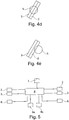
- the FIGS. 4a to 4e show such method.
- the figures show sections of an outer sensor arrangement 2 and an inner sensor arrangement 3. In FIG. 4a the ray of incidence approaches S of the outer sensor assembly 2 and irradiates this. In FIG. 4b is the incident beam S further advanced and also irradiates the inner sensor assembly 3.
- the closing device 6 is closed.
- the incident beam S moves further into the beam passage area 4.
- the incident beam S continues to move and will exit the beam passage area 4 at some point, and thereby, as shown in FIG FIG. 4d shown, first the inner sensor assembly 3 and then the outer sensor assembly 2 to rays.
- the incident beam S continues to move, and becomes, as in Figure 4e shown, then no longer irradiate the inner sensor assembly 3 and only irradiate the outer sensor assembly 2.
- the closing device 6 is opened again. This ensures that the closing device 6 is always closed when the incident beam S is within the beam passage area 4.
- a beam passage opening 5, each with a closing device 6 is provided for the left and the right eye, wherein the closing devices 6 are advantageously controlled independently of each other by the respective incident radiation S.
- the ambient radiation U is measured with the sensor 7 and the closing device 6 is closed and reopened only when the radiation intensity measured by at least the outer sensor arrangement 2 Incident radiation S is higher than the intensity of the ambient radiation U or the limit values are exceeded.
- the individual sensors 2a, 3a, the outer sensor assembly 2 and preferably also on the inner sensor assembly 3 are read out individually or at least in groups, so that the incident radiation S can be measured, and from an incident beam direction can be calculated, because it is known which of the sensors 2a, 3a were irradiated by the incident radiation S.
- the incident beam direction preferably also a time, a GPS position, a height, coordinates or a radiation intensity of the incident radiation S are measured and stored in a memory device 8a.
Landscapes
- Health & Medical Sciences (AREA)
- Physics & Mathematics (AREA)
- Ophthalmology & Optometry (AREA)
- Optics & Photonics (AREA)
- General Health & Medical Sciences (AREA)
- General Physics & Mathematics (AREA)
- Life Sciences & Earth Sciences (AREA)
- Vascular Medicine (AREA)
- Heart & Thoracic Surgery (AREA)
- Animal Behavior & Ethology (AREA)
- Biomedical Technology (AREA)
- Public Health (AREA)
- Veterinary Medicine (AREA)
- Engineering & Computer Science (AREA)
- Spectroscopy & Molecular Physics (AREA)
- Eyeglasses (AREA)
- Photometry And Measurement Of Optical Pulse Characteristics (AREA)
Priority Applications (1)
| Application Number | Priority Date | Filing Date | Title |
|---|---|---|---|
| PL15744138T PL3166552T3 (pl) | 2014-07-13 | 2015-07-13 | Urządzenie i sposób do ochrony oczu przed promieniowaniem |
Applications Claiming Priority (2)
| Application Number | Priority Date | Filing Date | Title |
|---|---|---|---|
| EP14176838 | 2014-07-13 | ||
| PCT/EP2015/065958 WO2016008839A1 (de) | 2014-07-13 | 2015-07-13 | Vorrichtung und verfahren zum schutz der augen vor strahlung |
Publications (2)
| Publication Number | Publication Date |
|---|---|
| EP3166552A1 EP3166552A1 (de) | 2017-05-17 |
| EP3166552B1 true EP3166552B1 (de) | 2018-09-12 |
Family
ID=51178752
Family Applications (1)
| Application Number | Title | Priority Date | Filing Date |
|---|---|---|---|
| EP15744138.7A Active EP3166552B1 (de) | 2014-07-13 | 2015-07-13 | Vorrichtung und verfahren zum schutz der augen vor strahlung |
Country Status (8)
| Country | Link |
|---|---|
| US (1) | US10268052B2 (pl) |
| EP (1) | EP3166552B1 (pl) |
| CN (1) | CN106535839B (pl) |
| AU (1) | AU2015289254B2 (pl) |
| CA (1) | CA2957636C (pl) |
| ES (1) | ES2701252T3 (pl) |
| PL (1) | PL3166552T3 (pl) |
| WO (1) | WO2016008839A1 (pl) |
Families Citing this family (3)
| Publication number | Priority date | Publication date | Assignee | Title |
|---|---|---|---|---|
| CN108121085A (zh) * | 2018-01-09 | 2018-06-05 | 成都黑贝智能科技有限公司 | 适用于多种光照环境的眼部保护设备 |
| CN111513922B (zh) * | 2020-04-10 | 2022-05-17 | 温州医科大学附属眼视光医院 | 一种可计时的光敏弱视治疗遮盖眼罩 |
| CN114580211B (zh) * | 2022-04-24 | 2022-07-15 | 天津航大天元航空技术有限公司 | 一种光伏发电设备的视觉影响评估方法及装置 |
Family Cites Families (10)
| Publication number | Priority date | Publication date | Assignee | Title |
|---|---|---|---|---|
| DE3437704A1 (de) * | 1984-01-02 | 1985-07-11 | Jenoptik Jena Gmbh, Ddr 6900 Jena | Empfaengereinheit fuer eine blendschutzbrille |
| DE3634508C1 (en) * | 1986-10-09 | 1988-06-16 | Rupert Fuerthbauer | Optical filter with automatic control of the optical transmission |
| US4848890A (en) * | 1987-08-27 | 1989-07-18 | Grumman Aerospace Corporation | Visor with point sun blocking |
| DE69129759D1 (de) * | 1990-12-14 | 1998-08-13 | Humphrey Eng Inc | Verfahren und vorrichtung zur steuerung des grades der helligkeitsempfindung mittels einer zeitveränderlichen blende |
| US5255117A (en) * | 1992-02-14 | 1993-10-19 | The United States Of America As Represented By The Secretary Of The Navy | Advanced eye or sensor protection and high speed variable optical attenuation system |
| US5671035A (en) * | 1995-06-07 | 1997-09-23 | Barnes; Elwood E. | Light intensity reduction apparatus and method |
| FR2742555B1 (fr) * | 1995-12-18 | 1998-02-13 | Aerospatiale | Dispositif de protection des yeux |
| KR101285602B1 (ko) * | 2011-02-15 | 2013-07-12 | 서운수 | 자동 차광 고글 |
| CN103688157A (zh) * | 2011-05-12 | 2014-03-26 | 阿拉基防御系统公司 | 光学危险回避装置和方法 |
| US9442293B2 (en) * | 2014-05-06 | 2016-09-13 | Microsoft Technology Licensing, Llc | Composite variable light attenuator |
-
2015
- 2015-07-13 CA CA2957636A patent/CA2957636C/en active Active
- 2015-07-13 US US15/322,470 patent/US10268052B2/en active Active
- 2015-07-13 PL PL15744138T patent/PL3166552T3/pl unknown
- 2015-07-13 EP EP15744138.7A patent/EP3166552B1/de active Active
- 2015-07-13 CN CN201580038045.0A patent/CN106535839B/zh active Active
- 2015-07-13 WO PCT/EP2015/065958 patent/WO2016008839A1/de not_active Ceased
- 2015-07-13 ES ES15744138T patent/ES2701252T3/es active Active
- 2015-07-13 AU AU2015289254A patent/AU2015289254B2/en active Active
Non-Patent Citations (1)
| Title |
|---|
| None * |
Also Published As
| Publication number | Publication date |
|---|---|
| PL3166552T3 (pl) | 2019-02-28 |
| AU2015289254B2 (en) | 2017-08-17 |
| CN106535839A (zh) | 2017-03-22 |
| CN106535839B (zh) | 2019-03-22 |
| US20170199397A1 (en) | 2017-07-13 |
| WO2016008839A9 (de) | 2016-03-17 |
| AU2015289254A1 (en) | 2017-01-19 |
| CA2957636C (en) | 2022-05-10 |
| EP3166552A1 (de) | 2017-05-17 |
| ES2701252T3 (es) | 2019-02-21 |
| US10268052B2 (en) | 2019-04-23 |
| CA2957636A1 (en) | 2016-01-21 |
| WO2016008839A1 (de) | 2016-01-21 |
Similar Documents
| Publication | Publication Date | Title |
|---|---|---|
| DE3634508C1 (en) | Optical filter with automatic control of the optical transmission | |
| DE3650185T2 (de) | Polarisierungslinse, undurchlässig für ultraviolette strahlung und blaues licht. | |
| EP3615984B1 (de) | Head-up-display | |
| EP3166552B1 (de) | Vorrichtung und verfahren zum schutz der augen vor strahlung | |
| CH704436B1 (de) | Filter für eine Filtriervorrichtung, insbesondere für einen entlastenden sowie präventiven Augenschutz als Brille, Sonnenbrille oder Scheibe, und Filtriervorrichtung mit mindestens einem solchen Filter. | |
| EP1110450B1 (de) | Vogelschutzvorrichtung für einen transparenten Stoff, Glas mit Vogelschutzvorrichtung | |
| WO2018028759A1 (de) | Laserschutzbrille zur vollständigen, wellenlängenunabhängigen abschirmung von hochleistungslaserstrahlen | |
| EP3203262B1 (de) | Optoelektronische vorrichtung zur absicherung einer gefahrenquelle | |
| EP3807118B1 (de) | Gerät zum generieren eines virtuellen bildes mit störlichtunterdrückung | |
| EP2463196A1 (de) | Passiver Eigenschutz für Fahrzeuge, insbesondere für Flugobjekt, und Objekte mit wenigstens einem Fenster | |
| DE3511263A1 (de) | Strahlungsschutzbrille | |
| DE102010006661B4 (de) | Verfahren und Vorrichtung zum Abbilden einer Umgebung auf eine Detektoreinrichtung | |
| DE102014205907B4 (de) | Schutzvorrichtung zum Schutz vor Laserstrahlung | |
| EP2462823B1 (de) | Schutzausrüstung für Sicherheitskräfte | |
| EP4266268A1 (de) | Schleuse; system, umfassend eine schleuse; verfahren zur steuerung eines personenflusses und/oder zur personenkontrolle; computerprogrammprodukt | |
| DE102014205908B4 (de) | Schutzvorrichtung zum Schutz vor Laserstrahlung | |
| DE102004040148A1 (de) | Lichtschutzbrille | |
| WO2021228452A1 (de) | Kraftfahrzeug | |
| DE813235C (de) | Blendschutzeinrichtung zum Schutz gegen Sonne, Scheinwerfer oder andere natuerliche oder kuenstliche Lichtquellen, vorzugsweise fuer Fahrzeuge | |
| WO2018104230A1 (de) | Schutzvorrichtung, schutzvorrichtung und helm zum schutz vor lichteinstrahlung | |
| DE8815377U1 (de) | Augenblendschutzvorrichtung | |
| DE825133C (de) | Schutzbrille | |
| EP1164990A1 (de) | Gesichtsschutz | |
| DD252447A1 (de) | Optisches system zum schutz gegen uv- und/oder ir-laserstrahlung | |
| DE102019107201A1 (de) | Laserschutzbrille, Laserschutzvorsatzfilter oder Laserschutzobjektiv |
Legal Events
| Date | Code | Title | Description |
|---|---|---|---|
| STAA | Information on the status of an ep patent application or granted ep patent |
Free format text: STATUS: THE INTERNATIONAL PUBLICATION HAS BEEN MADE |
|
| PUAI | Public reference made under article 153(3) epc to a published international application that has entered the european phase |
Free format text: ORIGINAL CODE: 0009012 |
|
| STAA | Information on the status of an ep patent application or granted ep patent |
Free format text: STATUS: REQUEST FOR EXAMINATION WAS MADE |
|
| 17P | Request for examination filed |
Effective date: 20170110 |
|
| AK | Designated contracting states |
Kind code of ref document: A1 Designated state(s): AL AT BE BG CH CY CZ DE DK EE ES FI FR GB GR HR HU IE IS IT LI LT LU LV MC MK MT NL NO PL PT RO RS SE SI SK SM TR |
|
| AX | Request for extension of the european patent |
Extension state: BA ME |
|
| DAV | Request for validation of the european patent (deleted) | ||
| DAX | Request for extension of the european patent (deleted) | ||
| GRAP | Despatch of communication of intention to grant a patent |
Free format text: ORIGINAL CODE: EPIDOSNIGR1 |
|
| STAA | Information on the status of an ep patent application or granted ep patent |
Free format text: STATUS: GRANT OF PATENT IS INTENDED |
|
| INTG | Intention to grant announced |
Effective date: 20180313 |
|
| GRAS | Grant fee paid |
Free format text: ORIGINAL CODE: EPIDOSNIGR3 |
|
| GRAA | (expected) grant |
Free format text: ORIGINAL CODE: 0009210 |
|
| STAA | Information on the status of an ep patent application or granted ep patent |
Free format text: STATUS: THE PATENT HAS BEEN GRANTED |
|
| AK | Designated contracting states |
Kind code of ref document: B1 Designated state(s): AL AT BE BG CH CY CZ DE DK EE ES FI FR GB GR HR HU IE IS IT LI LT LU LV MC MK MT NL NO PL PT RO RS SE SI SK SM TR |
|
| REG | Reference to a national code |
Ref country code: GB Ref legal event code: FG4D Free format text: NOT ENGLISH |
|
| REG | Reference to a national code |
Ref country code: CH Ref legal event code: EP |
|
| REG | Reference to a national code |
Ref country code: IE Ref legal event code: FG4D Free format text: LANGUAGE OF EP DOCUMENT: GERMAN |
|
| REG | Reference to a national code |
Ref country code: DE Ref legal event code: R096 Ref document number: 502015005864 Country of ref document: DE |
|
| REG | Reference to a national code |
Ref country code: AT Ref legal event code: REF Ref document number: 1039686 Country of ref document: AT Kind code of ref document: T Effective date: 20181015 |
|
| REG | Reference to a national code |
Ref country code: SE Ref legal event code: TRGR |
|
| REG | Reference to a national code |
Ref country code: NL Ref legal event code: FP |
|
| REG | Reference to a national code |
Ref country code: LT Ref legal event code: MG4D |
|
| PG25 | Lapsed in a contracting state [announced via postgrant information from national office to epo] |
Ref country code: BG Free format text: LAPSE BECAUSE OF FAILURE TO SUBMIT A TRANSLATION OF THE DESCRIPTION OR TO PAY THE FEE WITHIN THE PRESCRIBED TIME-LIMIT Effective date: 20181212 Ref country code: LT Free format text: LAPSE BECAUSE OF FAILURE TO SUBMIT A TRANSLATION OF THE DESCRIPTION OR TO PAY THE FEE WITHIN THE PRESCRIBED TIME-LIMIT Effective date: 20180912 Ref country code: RS Free format text: LAPSE BECAUSE OF FAILURE TO SUBMIT A TRANSLATION OF THE DESCRIPTION OR TO PAY THE FEE WITHIN THE PRESCRIBED TIME-LIMIT Effective date: 20180912 Ref country code: GR Free format text: LAPSE BECAUSE OF FAILURE TO SUBMIT A TRANSLATION OF THE DESCRIPTION OR TO PAY THE FEE WITHIN THE PRESCRIBED TIME-LIMIT Effective date: 20181213 Ref country code: FI Free format text: LAPSE BECAUSE OF FAILURE TO SUBMIT A TRANSLATION OF THE DESCRIPTION OR TO PAY THE FEE WITHIN THE PRESCRIBED TIME-LIMIT Effective date: 20180912 |
|
| REG | Reference to a national code |
Ref country code: NO Ref legal event code: T2 Effective date: 20180912 |
|
| REG | Reference to a national code |
Ref country code: ES Ref legal event code: FG2A Ref document number: 2701252 Country of ref document: ES Kind code of ref document: T3 Effective date: 20190221 |
|
| PG25 | Lapsed in a contracting state [announced via postgrant information from national office to epo] |
Ref country code: LV Free format text: LAPSE BECAUSE OF FAILURE TO SUBMIT A TRANSLATION OF THE DESCRIPTION OR TO PAY THE FEE WITHIN THE PRESCRIBED TIME-LIMIT Effective date: 20180912 Ref country code: AL Free format text: LAPSE BECAUSE OF FAILURE TO SUBMIT A TRANSLATION OF THE DESCRIPTION OR TO PAY THE FEE WITHIN THE PRESCRIBED TIME-LIMIT Effective date: 20180912 Ref country code: HR Free format text: LAPSE BECAUSE OF FAILURE TO SUBMIT A TRANSLATION OF THE DESCRIPTION OR TO PAY THE FEE WITHIN THE PRESCRIBED TIME-LIMIT Effective date: 20180912 |
|
| PG25 | Lapsed in a contracting state [announced via postgrant information from national office to epo] |
Ref country code: IS Free format text: LAPSE BECAUSE OF FAILURE TO SUBMIT A TRANSLATION OF THE DESCRIPTION OR TO PAY THE FEE WITHIN THE PRESCRIBED TIME-LIMIT Effective date: 20190112 Ref country code: EE Free format text: LAPSE BECAUSE OF FAILURE TO SUBMIT A TRANSLATION OF THE DESCRIPTION OR TO PAY THE FEE WITHIN THE PRESCRIBED TIME-LIMIT Effective date: 20180912 Ref country code: CZ Free format text: LAPSE BECAUSE OF FAILURE TO SUBMIT A TRANSLATION OF THE DESCRIPTION OR TO PAY THE FEE WITHIN THE PRESCRIBED TIME-LIMIT Effective date: 20180912 Ref country code: RO Free format text: LAPSE BECAUSE OF FAILURE TO SUBMIT A TRANSLATION OF THE DESCRIPTION OR TO PAY THE FEE WITHIN THE PRESCRIBED TIME-LIMIT Effective date: 20180912 |
|
| PG25 | Lapsed in a contracting state [announced via postgrant information from national office to epo] |
Ref country code: PT Free format text: LAPSE BECAUSE OF FAILURE TO SUBMIT A TRANSLATION OF THE DESCRIPTION OR TO PAY THE FEE WITHIN THE PRESCRIBED TIME-LIMIT Effective date: 20190112 Ref country code: SM Free format text: LAPSE BECAUSE OF FAILURE TO SUBMIT A TRANSLATION OF THE DESCRIPTION OR TO PAY THE FEE WITHIN THE PRESCRIBED TIME-LIMIT Effective date: 20180912 Ref country code: SK Free format text: LAPSE BECAUSE OF FAILURE TO SUBMIT A TRANSLATION OF THE DESCRIPTION OR TO PAY THE FEE WITHIN THE PRESCRIBED TIME-LIMIT Effective date: 20180912 |
|
| REG | Reference to a national code |
Ref country code: DE Ref legal event code: R097 Ref document number: 502015005864 Country of ref document: DE |
|
| PLBE | No opposition filed within time limit |
Free format text: ORIGINAL CODE: 0009261 |
|
| STAA | Information on the status of an ep patent application or granted ep patent |
Free format text: STATUS: NO OPPOSITION FILED WITHIN TIME LIMIT |
|
| PG25 | Lapsed in a contracting state [announced via postgrant information from national office to epo] |
Ref country code: DK Free format text: LAPSE BECAUSE OF FAILURE TO SUBMIT A TRANSLATION OF THE DESCRIPTION OR TO PAY THE FEE WITHIN THE PRESCRIBED TIME-LIMIT Effective date: 20180912 |
|
| 26N | No opposition filed |
Effective date: 20190613 |
|
| PG25 | Lapsed in a contracting state [announced via postgrant information from national office to epo] |
Ref country code: SI Free format text: LAPSE BECAUSE OF FAILURE TO SUBMIT A TRANSLATION OF THE DESCRIPTION OR TO PAY THE FEE WITHIN THE PRESCRIBED TIME-LIMIT Effective date: 20180912 |
|
| PG25 | Lapsed in a contracting state [announced via postgrant information from national office to epo] |
Ref country code: MC Free format text: LAPSE BECAUSE OF FAILURE TO SUBMIT A TRANSLATION OF THE DESCRIPTION OR TO PAY THE FEE WITHIN THE PRESCRIBED TIME-LIMIT Effective date: 20180912 |
|
| PG25 | Lapsed in a contracting state [announced via postgrant information from national office to epo] |
Ref country code: LU Free format text: LAPSE BECAUSE OF NON-PAYMENT OF DUE FEES Effective date: 20190713 |
|
| PG25 | Lapsed in a contracting state [announced via postgrant information from national office to epo] |
Ref country code: CY Free format text: LAPSE BECAUSE OF FAILURE TO SUBMIT A TRANSLATION OF THE DESCRIPTION OR TO PAY THE FEE WITHIN THE PRESCRIBED TIME-LIMIT Effective date: 20180912 |
|
| PG25 | Lapsed in a contracting state [announced via postgrant information from national office to epo] |
Ref country code: MT Free format text: LAPSE BECAUSE OF FAILURE TO SUBMIT A TRANSLATION OF THE DESCRIPTION OR TO PAY THE FEE WITHIN THE PRESCRIBED TIME-LIMIT Effective date: 20180912 Ref country code: HU Free format text: LAPSE BECAUSE OF FAILURE TO SUBMIT A TRANSLATION OF THE DESCRIPTION OR TO PAY THE FEE WITHIN THE PRESCRIBED TIME-LIMIT; INVALID AB INITIO Effective date: 20150713 |
|
| PG25 | Lapsed in a contracting state [announced via postgrant information from national office to epo] |
Ref country code: MK Free format text: LAPSE BECAUSE OF FAILURE TO SUBMIT A TRANSLATION OF THE DESCRIPTION OR TO PAY THE FEE WITHIN THE PRESCRIBED TIME-LIMIT Effective date: 20180912 |
|
| PGFP | Annual fee paid to national office [announced via postgrant information from national office to epo] |
Ref country code: PL Payment date: 20250627 Year of fee payment: 11 |
|
| PGFP | Annual fee paid to national office [announced via postgrant information from national office to epo] |
Ref country code: GB Payment date: 20250506 Year of fee payment: 11 |
|
| PGFP | Annual fee paid to national office [announced via postgrant information from national office to epo] |
Ref country code: NL Payment date: 20250618 Year of fee payment: 11 Ref country code: BE Payment date: 20250625 Year of fee payment: 11 |
|
| PGFP | Annual fee paid to national office [announced via postgrant information from national office to epo] |
Ref country code: FR Payment date: 20250618 Year of fee payment: 11 |
|
| PGFP | Annual fee paid to national office [announced via postgrant information from national office to epo] |
Ref country code: IE Payment date: 20250508 Year of fee payment: 11 |
|
| PGFP | Annual fee paid to national office [announced via postgrant information from national office to epo] |
Ref country code: SE Payment date: 20250624 Year of fee payment: 11 |
|
| PGFP | Annual fee paid to national office [announced via postgrant information from national office to epo] |
Ref country code: ES Payment date: 20250804 Year of fee payment: 11 |
|
| PGFP | Annual fee paid to national office [announced via postgrant information from national office to epo] |
Ref country code: DE Payment date: 20250619 Year of fee payment: 11 |
|
| PGFP | Annual fee paid to national office [announced via postgrant information from national office to epo] |
Ref country code: NO Payment date: 20250701 Year of fee payment: 11 |
|
| PGFP | Annual fee paid to national office [announced via postgrant information from national office to epo] |
Ref country code: IT Payment date: 20250619 Year of fee payment: 11 Ref country code: TR Payment date: 20250709 Year of fee payment: 11 |
|
| PGFP | Annual fee paid to national office [announced via postgrant information from national office to epo] |
Ref country code: AT Payment date: 20250702 Year of fee payment: 11 |
|
| PGFP | Annual fee paid to national office [announced via postgrant information from national office to epo] |
Ref country code: CH Payment date: 20250801 Year of fee payment: 11 |