EP3166552B1 - Device and method for protecting the eyes from radiation - Google Patents
Device and method for protecting the eyes from radiation Download PDFInfo
- Publication number
- EP3166552B1 EP3166552B1 EP15744138.7A EP15744138A EP3166552B1 EP 3166552 B1 EP3166552 B1 EP 3166552B1 EP 15744138 A EP15744138 A EP 15744138A EP 3166552 B1 EP3166552 B1 EP 3166552B1
- Authority
- EP
- European Patent Office
- Prior art keywords
- radiation
- sensor arrangement
- closing device
- incident
- incident radiation
- Prior art date
- Legal status (The legal status is an assumption and is not a legal conclusion. Google has not performed a legal analysis and makes no representation as to the accuracy of the status listed.)
- Active
Links
Images


Classifications
-
- G—PHYSICS
- G02—OPTICS
- G02C—SPECTACLES; SUNGLASSES OR GOGGLES INSOFAR AS THEY HAVE THE SAME FEATURES AS SPECTACLES; CONTACT LENSES
- G02C7/00—Optical parts
- G02C7/10—Filters, e.g. for facilitating adaptation of the eyes to the dark; Sunglasses
- G02C7/104—Filters, e.g. for facilitating adaptation of the eyes to the dark; Sunglasses having spectral characteristics for purposes other than sun-protection
-
- A—HUMAN NECESSITIES
- A61—MEDICAL OR VETERINARY SCIENCE; HYGIENE
- A61F—FILTERS IMPLANTABLE INTO BLOOD VESSELS; PROSTHESES; DEVICES PROVIDING PATENCY TO, OR PREVENTING COLLAPSING OF, TUBULAR STRUCTURES OF THE BODY, e.g. STENTS; ORTHOPAEDIC, NURSING OR CONTRACEPTIVE DEVICES; FOMENTATION; TREATMENT OR PROTECTION OF EYES OR EARS; BANDAGES, DRESSINGS OR ABSORBENT PADS; FIRST-AID KITS
- A61F9/00—Methods or devices for treatment of the eyes; Devices for putting in contact-lenses; Devices to correct squinting; Apparatus to guide the blind; Protective devices for the eyes, carried on the body or in the hand
- A61F9/02—Goggles
- A61F9/022—Use of special optical filters, e.g. multiple layers, filters for protection against laser light or light from nuclear explosions, screens with different filter properties on different parts of the screen; Rotating slit-discs
- A61F9/023—Use of special optical filters, e.g. multiple layers, filters for protection against laser light or light from nuclear explosions, screens with different filter properties on different parts of the screen; Rotating slit-discs with variable transmission, e.g. photochromic
-
- A—HUMAN NECESSITIES
- A61—MEDICAL OR VETERINARY SCIENCE; HYGIENE
- A61F—FILTERS IMPLANTABLE INTO BLOOD VESSELS; PROSTHESES; DEVICES PROVIDING PATENCY TO, OR PREVENTING COLLAPSING OF, TUBULAR STRUCTURES OF THE BODY, e.g. STENTS; ORTHOPAEDIC, NURSING OR CONTRACEPTIVE DEVICES; FOMENTATION; TREATMENT OR PROTECTION OF EYES OR EARS; BANDAGES, DRESSINGS OR ABSORBENT PADS; FIRST-AID KITS
- A61F9/00—Methods or devices for treatment of the eyes; Devices for putting in contact-lenses; Devices to correct squinting; Apparatus to guide the blind; Protective devices for the eyes, carried on the body or in the hand
- A61F9/04—Eye-masks ; Devices to be worn on the face, not intended for looking through; Eye-pads for sunbathing
- A61F9/045—Eye-shades or visors; Shields beside, between or below the eyes
-
- G—PHYSICS
- G02—OPTICS
- G02B—OPTICAL ELEMENTS, SYSTEMS OR APPARATUS
- G02B26/00—Optical devices or arrangements for the control of light using movable or deformable optical elements
- G02B26/02—Optical devices or arrangements for the control of light using movable or deformable optical elements for controlling the intensity of light
-
- G—PHYSICS
- G02—OPTICS
- G02C—SPECTACLES; SUNGLASSES OR GOGGLES INSOFAR AS THEY HAVE THE SAME FEATURES AS SPECTACLES; CONTACT LENSES
- G02C7/00—Optical parts
- G02C7/10—Filters, e.g. for facilitating adaptation of the eyes to the dark; Sunglasses
- G02C7/101—Filters, e.g. for facilitating adaptation of the eyes to the dark; Sunglasses having an electro-optical light valve
-
- G—PHYSICS
- G02—OPTICS
- G02C—SPECTACLES; SUNGLASSES OR GOGGLES INSOFAR AS THEY HAVE THE SAME FEATURES AS SPECTACLES; CONTACT LENSES
- G02C7/00—Optical parts
- G02C7/16—Shades; shields; Obturators, e.g. with pinhole, with slot
Definitions
- the invention relates to a device for protecting the eyes from radiation.
- the invention further relates to a method of protecting the eyes from radiation
- the object of the invention is a device and a method for eye protection of persons.
- the dependent claims 2 to 10 relate to further advantageous embodiments.
- the object is further achieved by a method comprising the features of claim 11.
- the dependent claims 12 to 15 relate to further advantageous method steps.
- a device for protecting the eyes from radiation comprising at least two sensor arrangements, an outer sensor arrangement and an inner sensor arrangement, each sensor arrangement having a A plurality of successively arranged beam sensors disposed along each closed loop, and wherein the inner sensor assembly is enclosed by the outer sensor assembly, and wherein the outer and inner sensor assemblies are juxtaposed, and wherein the inner sensor assembly encases a beam passage region, and wherein the beam passage region has a beam passage opening, and wherein a closing device is arranged with respect to the beam passage region such that an incident radiation passing through the beam passage opening either passes through which is completely closed or at least partially attenuated by a tinted surface, and comprising a drive device which is connected to the inner sensor arrangement, the outer sensor arrangement and the closing device.
- each sensor arrangement comprises a plurality of successively arranged beam sensors which are arranged along each of a closed curve, wherein the inner sensor arrangement is enclosed by the outer sensor arrangement, and wherein the inner sensor arrangement encloses a beam passage area, and wherein a beam passage opening in the beam passage area and wherein a closing device is arranged such that an incident radiation passing through the beam passage opening is either transmitted or at least partially attenuated, the closing device being closed when the outer sensor arrangement and subsequently the inner sensor arrangement is irradiated by the incident radiation, or the second sensor arrangement is irradiated and wherein the closing device is reopened when initially the inner sensor arrangement and subsequently only the outer sensor arrangement is irradiated by the incident radiation and wherein both sensor arrangement are ir
- light is meant herein visible light in a wavelength range of 380nm to 780nm.
- Laser beams have a different point size or a different beam diameter depending on the distance of the attack.
- the point size can be about 10m, at 2500m about 2.5m, at, 1250 m have about 1.25m.
- closer distances like 50m about 0.05m and at 25m 0.025m and at a distance of 10m by only 0.01m.
- the inventive device has the advantage that even a small spot size or a small radiation diameter can be safely hidden because the device detects the approach of the beam and the closing device interrupts the beam as soon as it illuminates the outer sensor assembly and subsequently the inner sensor assembly, so the beam no longer falls on the eye. As soon as the jet has returned to the outer sensor arrangement via the inner sensor arrangement and the inner sensor arrangement is no longer illuminated, the closing device can be opened again. In practice, this results in the closing device being closed only for a very short time, so that the pilot's eye is covered only for a very short time, and the pilot has a clear view most of the time without being distracted to become.
- a closing device preferably a mechanical closing device or else an electronic closing device is used, as are known for example from cameras, with shutter speeds of preferably in the range of 10 -3 to 10 -18 seconds.
- the shutter speeds can thus be very short, for example in the range of milliseconds to atto seconds.
- An eye blow lasts about 0.25s.
- the eye is thus too slow to be effectively protected against laser attacks.
- Shuttering time is understood to be the time duration in order to transfer the closing device from the opened state into the closed state.
- the short shutter speed of the device according to the invention thus has the advantage that the eye of the pilot or affected person can be better protected because the eyelid closes only in about 0.25 seconds, especially in laser attacks which are carried out from short and distant distance and have a higher performance.
- the device according to the invention has the particularly advantageous feature that the closure or closing device is preferably opened again immediately, and this preferably even individually, ie, the right and left sides operate autonomously as soon as the laser beam is no longer within the beam passage area that the pilot locomotive driver, bus driver, etc. on the attacked eye very quickly again has a clear view.
- the opening time that is to say the time duration in order to transfer the closing device from the closed state into the opened state, is likewise preferably in the range from 10 -3 to 10 -18 seconds.
- the closing device preferably remains closed until the laser beam is no longer within the beam passage area, in order to be opened immediately thereafter.
- the closing device remains dependent on the irradiation duration during which the beam passage area is irradiated by the laser beam is, closed, the irradiation time depending on the situation may be in the range of fractions of seconds, in unfavorable cases with a longer irradiation time, but also for example in the range of several seconds.
- a separate closure is arranged in front of the left and the right eye, the two closures being controlled independently of one another. This makes it possible for a laser attack with small laser beam sizes that only either the left or the right eye is attacked simultaneously, with the result that usually at least one eye has a clear view.
- the device according to the invention has the advantage that the direction of movement of a radiation attack can be detected because the device has two sensor arrangements arranged next to one another, each sensor arrangement having a plurality of individually measurable sensors. Based on these measurements, it is possible to calculate the radiant intensity using an evaluation device.
- the measured direction of incidence is stored in the device according to the invention, preferably together with further data such as the time of day, the radiation intensity or the location, coordinates based on GPS data, for example, or the altitude, for example with MEMS sensors (CRG20, FIG. SiRRS01, PinPoint, Gemini) and electronics and can be forwarded via communication telephone, SMS, etc. Based on these data, it is preferably immediately or subsequently possible to at least approximately determine the emission location of the laser attack.
- a mechanical or electronic locking device is used, as is known for example in cameras.
- Such closing devices are also referred to as skids.
- a closing device In the opened state, such a closing device usually has a radiation transmission of 100% or less, ie the beam entering through the closing device is subject to little or no damping.
- the device according to the invention is therefore particularly advantageous for pilots, since the standards ISO12311-1, ISO12312-1 or EN166 stipulate that a light transmission of 75% is required.
- the device according to the invention thus also has the advantage that a good color recognition is ensured and no color impairment takes place, since no wavelengths are filtered out.
- the device according to the invention for example, complies with standards ISO 12312-1, ISO12311-1, EN166 as regards color recognition, in particular of modern colored digital or analog displays, in aviation, shipping, railways and in the traffic sector.
- a mechanical closing device also has the advantage that it can easily interrupt radiation in a large wave range.
- sensors are used with a sensitivity in the wave range between 400 nm to 1100 nm.
- polarization filters or laser safety goggles are known.
- a disadvantage of polarizing filters is the fact that they are not allowed in aviation, as the Aircraft instruments are no longer recognizable.
- a disadvantage of laser safety glasses is the fact that lasers are known with a variety of different wavelengths. However, laser goggles can only filter the fixed and preset wavelengths so that there is a risk that a laser safety goggles used will not filter the irradiating laser.
- the inventive device has the further advantage that even laser attacks with high radiation strength can be completely blocked because the optical beam path is interrupted by a mechanical closing device.
- Known devices allow a residual radiation from a certain amount of radiation, so that no complete protection is guaranteed.
- a spot beam can penetrate an LCD and it depends on the angle at which the radiation enters the LCD, the beam can be stronger or weaker.
- the beam passage opening is completely closed by means of the closing device.
- the device according to the invention can also have at least one camera and at least one display, wherein the display is arranged inside the glasses, and the camera is arranged outside on the glasses, so that the camera can store data in 2D or 3D or in SWIR, MWIR, LWIR picks up an external image and displays it on the display, so that a pilot can see the environment as well as possible, even if both are closed are closed at short notice. If there is an interface of the computer, it is also possible to additionally display data such as flight data directly on the screen.
- the measuring device according to the invention can also comprise a filter which is arranged in front of the spectacles and filters incoming radiation such as UVC, UVB, UVA and blue light and infrared.
- the protection against laser attacks, increased radiation or stronger light which is based on a sophisticated UV, light and IR sensor system and the pulse in milli, micro, nano, pico, femto, atto-, zepto- up to yocto- seconds to the closure and gives at least one or more closures in milli, micro, nano, or close to atto or faster and can open.
- This laser and enhanced sunscreen is intended to better and faster protect the eye from dangerous and intense rays that exceed its limits, since the blink of an eye is only 0.25 seconds and is too slow in this high-energy range. It is important that the protection device works in the vicinity of one meter and in the far range. Today's laser goggles cover only certain wavelengths.
- Laser safety goggles are subject to the European Directives on Personal Protective Equipment (PPE Directive 89/686 / EEC). They are not allowed for road traffic. According to the standard DIN EN 207, the protection must withstand at least 10s. For example, higher protection against acids, bases or toxic or reactive gases and vapors.
- the sensors can also be protected from dirt and, depending on the field of application, are protected with the appropriate transparent or tinted material, such as quartz, polymers such as polycarbonate, polyesters, copolyesters, cellulose propionates, acetates or other polymers.
- the design of the laser protection must not only be from the front side but also all around the eye must be protected.
- the radiation must not come in either laterally or from above or below. It is important to maintain a very large field of vision so that safety does not suffer. Therefore, ensure at least 90 ° to 180 ° or more of field of view.
- the skin is generally less sensitive to laser radiation than the eye.
- the effect of laser beams on the skin depends very much on the intensity of the radiation and not only damage on the uppermost skin layer, but also the lower skin layer can be affected by the high intensity.
- High intensity laser radiation can cause burns, severe blistering and subsequent scarring of the skin.
- Fig. 1 shows a designed as a spectacle attachment device 1 for the protection of the eyes from radiation, preferably in the range of 100 nm to 1 mm and in particular against UV, light, or IR.
- the device 1 comprises at least two sensor arrangements 2, 3, an outer sensor arrangement 2 and an inner sensor arrangement 3, wherein each sensor arrangement 2, 3 comprises a plurality of successively following ones arranged radiation sensors 2a, 3a which are arranged along each of a closed curve 2b, 3b.
- the curve can run in a variety of possible forms, advantageously circular or oval, but also, for example, as a polygonal, for example, triangular or square.
- the inner sensor arrangement 3 is enclosed by the outer sensor arrangement 2, wherein the outer and the inner sensor arrangement 2, 3 are arranged lying against each other, and wherein the inner sensor arrangement 3 encloses a beam passage area 4.
- the beam passage region 4 has a beam passage opening 5.
- a mechanical closing device 6 is arranged with respect to the beam passage region 4 such that an incident radiation S passing through the beam passage opening 5 is either transmitted or at least partially attenuated.
- An in FIG. 5 illustrated electronic control device 8 is signal conductive with the inner sensor assembly 2, the outer sensor assembly 3 and the closing device 6 is connected.
- the closing device 6 comprises at least one mechanically movable element 6a, which either lets through the incident radiation S or at least partially attenuates it.
- the movable element 6a either completely passes the jet S or interrupts it completely.
- the closing device 6 preferably has a shutter time in the range of 10 -3 to 10 -18 seconds.
- the mechanically movable element 6a is preferably radiopaque or in different OD (Optical Density) configured and may in particular have a mirrored surface.
- the mechanically movable element 6a can also have a radiation transmission in the range from 5% to 99%.
- the device 1 may, as in FIG. 1 shown as glasses 10 or as in FIG. 2 shown configured as eyeglass attachment 10 of a pair of glasses 13.
- the glasses 13 may have corrective lenses.
- the glasses 13 may also have a protective filter so that it is colored and has a light transmittance in the range of 100% to 0%.
- the device 1 has an all-round cover 12 which prevents lateral non-entry.
- the FIGS. 1 and 2 show a device 1 for spectacles or spectacles, with two mutually spaced beam passage areas 4, each with a beam passage opening 5 and a respective closing device 6, each beam passage area 4 is surrounded by an inner and an outer sensor assembly 2,3.
- the two closing devices 6 are advantageously individually controllable.
- the illustrated device 1 advantageously comprises a surrounding beam sensor 7 for detecting the ambient radiation.
- the device 1 could also comprise an unillustrated, detachable optical filter, which is connectable to the device such that the optical filter in front of the sensor assembly 2,3, the beam passage region 4 and preferably also in front of the ambient beam sensor 7 is arranged to filter incoming beams, in particular to protect the ambient beam sensor 7 from excessive light intensity.
- an unillustrated, detachable optical filter which is connectable to the device such that the optical filter in front of the sensor assembly 2,3, the beam passage region 4 and preferably also in front of the ambient beam sensor 7 is arranged to filter incoming beams, in particular to protect the ambient beam sensor 7 from excessive light intensity.
- the device 1 has as in FIG. 5 1 illustrates a drive device 8 and preferably a memory device 8a and a data interface 8b.
- the drive device 8 is signal-conducting connected to the outer sensor arrangement 2 of the inner sensor arrangement 3 and the closing device 6.
- FIG. 3 shows an embodiment of a device 1 with outer and inner sensor assembly 2,3, beam passage area 4 and beam passage opening 5.
- the beam passage opening 5 is simultaneously the closing device 6, which is designed as an electro-optical radiation shutter, for example as an LCD radiation shutter.
- the device is operated in such a way that an incident radiation S passing through the beam passage opening 4 is either transmitted or at least partially and preferably attenuated, the closing device 6 being closed when the outer sensor arrangement 2 and subsequently the inner sensor arrangement 3 are irradiated by the incident radiation S, and wherein the closing device 6 is opened again when initially the inner sensor arrangement 3 and subsequently only the outer sensor arrangement 2 is irradiated by the incident radiation S.
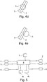
- the FIGS. 4a to 4e show such method.
- the figures show sections of an outer sensor arrangement 2 and an inner sensor arrangement 3. In FIG. 4a the ray of incidence approaches S of the outer sensor assembly 2 and irradiates this. In FIG. 4b is the incident beam S further advanced and also irradiates the inner sensor assembly 3.
- the closing device 6 is closed.
- the incident beam S moves further into the beam passage area 4.
- the incident beam S continues to move and will exit the beam passage area 4 at some point, and thereby, as shown in FIG FIG. 4d shown, first the inner sensor assembly 3 and then the outer sensor assembly 2 to rays.
- the incident beam S continues to move, and becomes, as in Figure 4e shown, then no longer irradiate the inner sensor assembly 3 and only irradiate the outer sensor assembly 2.
- the closing device 6 is opened again. This ensures that the closing device 6 is always closed when the incident beam S is within the beam passage area 4.
- a beam passage opening 5, each with a closing device 6 is provided for the left and the right eye, wherein the closing devices 6 are advantageously controlled independently of each other by the respective incident radiation S.
- the ambient radiation U is measured with the sensor 7 and the closing device 6 is closed and reopened only when the radiation intensity measured by at least the outer sensor arrangement 2 Incident radiation S is higher than the intensity of the ambient radiation U or the limit values are exceeded.
- the individual sensors 2a, 3a, the outer sensor assembly 2 and preferably also on the inner sensor assembly 3 are read out individually or at least in groups, so that the incident radiation S can be measured, and from an incident beam direction can be calculated, because it is known which of the sensors 2a, 3a were irradiated by the incident radiation S.
- the incident beam direction preferably also a time, a GPS position, a height, coordinates or a radiation intensity of the incident radiation S are measured and stored in a memory device 8a.
Landscapes
- Health & Medical Sciences (AREA)
- Physics & Mathematics (AREA)
- Ophthalmology & Optometry (AREA)
- Optics & Photonics (AREA)
- General Health & Medical Sciences (AREA)
- General Physics & Mathematics (AREA)
- Life Sciences & Earth Sciences (AREA)
- Vascular Medicine (AREA)
- Heart & Thoracic Surgery (AREA)
- Animal Behavior & Ethology (AREA)
- Biomedical Technology (AREA)
- Public Health (AREA)
- Veterinary Medicine (AREA)
- Engineering & Computer Science (AREA)
- Spectroscopy & Molecular Physics (AREA)
- Eyeglasses (AREA)
- Photometry And Measurement Of Optical Pulse Characteristics (AREA)
Description
Die Erfindung betrifft eine Vorrichtung zum Schutz der Augen vor Strahlung. Die Erfindung betrifft weiter ein Verfahren zum Schutz der Augen vor StrahlungThe invention relates to a device for protecting the eyes from radiation. The invention further relates to a method of protecting the eyes from radiation
Es finden immer mehr Attacken gegen Personen statt, bei welchen Laser, starke Lichtstrahlen oder Infrarot verwendet werden. Es ist daher ein Bedürfnis die Augen dieser Personen, beispielsweise Piloten, Busfahrer, Lokomotivführer, Polizisten oder Militär, besser vor solchen Strahlen zu schützen, um zum Beispiel gesundheitliche Schäden oder Unfälle zu vermeiden.There are more and more attacks against people using lasers, strong beams or infrared. It is therefore a need to protect the eyes of these persons, such as pilots, bus drivers, locomotive drivers, police officers or military, better from such radiation, for example, to avoid health damage or accidents.
Es sind Vorrichtungen zum Schutz der Augen vor Strahlungsattacken bekannt, beispielsweise aus den Dokumenten
Aufgabe der Erfindung ist ein Vorrichtung sowie ein Verfahren zum Augenschutz der Personen.The object of the invention is a device and a method for eye protection of persons.
Diese Aufgabe wird gelöst mit einer Vorrichtung aufweisend die Merkmale von Anspruch 1. Die abhängigen Ansprüche 2 bis 10 betreffen weitere vorteilhafte Ausgestaltungen. Die Aufgabe wird weiter gelöst mit einem Verfahren aufweisend die Merkmale von Anspruch 11. Die abhängigen Ansprüche 12 bis 15 betreffen weitere vorteilhafte Verfahrensschritte.This object is achieved with a device having the features of
Die Aufgabe wird insbesondere gelöst mit einer Vorrichtung zum Schutz der Augen vor Strahlung, vorzugsweise im Bereich von 100nm bis 1 mm und insbesondere vor UV, Licht, oder IR, umfassend zumindest zwei Sensoranordnungen, eine äussere Sensoranordnung sowie eine innere Sensoranordnung, wobei jede Sensoranordnung eine Mehrzahl von nacheinander folgend angeordneten Strahlensensoren aufweist welche entlang je eines geschlossenen Kurvenzuges angeordnet sind, und wobei die innere Sensoranordnung von der äusseren Sensoranordnung umschlossen ist, und wobei die äussere und die innere Sensoranordnung aneinander liegend angeordnet sind, und wobei die innere Sensoranordnung einen Strahlendurchgangsbereich umschliesst, und wobei der Strahlendurchgangsbereich eine Strahlendurchgangsöffnung aufweist, und wobei eine Schliessvorrichtung derart bezüglich dem Strahlendurchgangsbereich angeordnet ist, dass eine durch die Strahlendurchgangsöffnung tretende Einfallsstrahlung entweder durchgelassen oder komplett geschlossen oder zumindest teilweise durch eine getönte Oberfläche abgeschwächt wird, sowie umfassend eine Ansteuervorrichtung welche mit der inneren Sensoranordnung, der äusseren Sensoranordnung sowie der Schliessvorrichtung verbunden ist.The object is achieved in particular with a device for protecting the eyes from radiation, preferably in the range of 100 nm to 1 mm and in particular against UV, light or IR, comprising at least two sensor arrangements, an outer sensor arrangement and an inner sensor arrangement, each sensor arrangement having a A plurality of successively arranged beam sensors disposed along each closed loop, and wherein the inner sensor assembly is enclosed by the outer sensor assembly, and wherein the outer and inner sensor assemblies are juxtaposed, and wherein the inner sensor assembly encases a beam passage region, and wherein the beam passage region has a beam passage opening, and wherein a closing device is arranged with respect to the beam passage region such that an incident radiation passing through the beam passage opening either passes through which is completely closed or at least partially attenuated by a tinted surface, and comprising a drive device which is connected to the inner sensor arrangement, the outer sensor arrangement and the closing device.
Die Aufgabe wird weiter insbesondere gelöst mit einem Verfahren zum Schutz der Augen vor Strahlung, vorzugsweise im Bereich von 100nm bis 1 mm und insbesondere vor UV, Licht, oder IR, wobei das Auge von zumindest zwei Sensoranordnungen umgeben ist, einer äusseren Sensoranordnung sowie eine inneren Sensoranordnung, wobei jede Sensoranordnung eine Mehrzahl von nacheinander folgend angeordneten Strahlensensoren aufweist welche entlang je eines geschlossenen Kurvenzuges angeordnet sind, wobei die die innere Sensoranordnung von der äusseren Sensoranordnung umschlossen ist, und wobei die innere Sensoranordnung einen Strahlendurchgangsbereich umschliesst, und wobei eine Strahlendurchgangsöffnung im Strahlendurchgangsbereich angeordnet ist, und wobei eine Schliessvorrichtung derart angeordnet ist, dass eine durch die Strahlendurchgangsöffnung tretende Einfallsstrahlung entweder durchgelassen oder zumindest teilweise abgeschwächt wird, wobei die Schliessvorrichtung geschlossen wird, wenn die äussere Sensoranordnung und nachfolgend die innere Sensoranordnung von der Einfallsstrahlung bestrahlt wird, oder nur die zweite Sensoranordnung bestrahlt wird und wobei die Schliessvorrichtung wieder geöffnet wird, wenn vorerst die innere Sensoranordnung und nachfolgend nur noch die äussere Sensoranordnung von der Einfallsstrahlung bestrahlt wird und wobei beide Sensoranordnung miteinander bestrahlt werden, dann wird die Schliessvorrichtung geschlossen, sobald die programmierten Werte überschritten werden.The object is further achieved in particular with a method for protecting the eyes from radiation, preferably in the range from 100 nm to 1 mm and in particular from UV, light or IR, the eye being surrounded by at least two sensor arrangements, an outer sensor arrangement and an inner one Sensor arrangement, wherein each sensor arrangement comprises a plurality of successively arranged beam sensors which are arranged along each of a closed curve, wherein the inner sensor arrangement is enclosed by the outer sensor arrangement, and wherein the inner sensor arrangement encloses a beam passage area, and wherein a beam passage opening in the beam passage area and wherein a closing device is arranged such that an incident radiation passing through the beam passage opening is either transmitted or at least partially attenuated, the closing device being closed when the outer sensor arrangement and subsequently the inner sensor arrangement is irradiated by the incident radiation, or the second sensor arrangement is irradiated and wherein the closing device is reopened when initially the inner sensor arrangement and subsequently only the outer sensor arrangement is irradiated by the incident radiation and wherein both sensor arrangement are irradiated with each other, then the closing device is closed as soon as the programmed values are exceeded.
Unter dem Begriff "Licht" wird hierin sichtbares Licht in einem Wellenbereich von 380nm bis 780 nm verstanden.By the term "light" is meant herein visible light in a wavelength range of 380nm to 780nm.
Strahlungsattacken werden häufig mit Lasern durchgeführt. So werden beispielsweise Piloten durch Laserattacken geblendet. Laserstrahlen haben abhängig von der Distanz der Attacke eine unterschiedliche Punktgrösse beziehungsweise einen unterschiedlichen Strahlendurchmesser. Bei 10000m Distanz kann die Punktgrösse ca. 10m betragen, bei 2500m ca. 2.5m, bei, 1250 m ca. 1.25m haben. Bei näheren Distanzen wie 50m ca. 0.05m und bei 25m 0.025m und bei einer Distanz von 10m von nur 0.01m.Radiation attacks are often performed with lasers. For example, pilots are blinded by laser attacks. Laser beams have a different point size or a different beam diameter depending on the distance of the attack. At 10000m distance, the point size can be about 10m, at 2500m about 2.5m, at, 1250 m have about 1.25m. At closer distances like 50m about 0.05m and at 25m 0.025m and at a distance of 10m by only 0.01m.
Die erfindungsgemässe Vorrichtung weist den Vorteil auf, dass auch eine kleine Punktgrösse beziehungsweise ein kleiner Strahlungsdurchmesser sicher ausgeblendet werden kann, weil die Vorrichtung das Annähern des Strahls erkennt und die Schliessvorrichtung den Strahl unterbricht, sobald dieser die äussere Sensoranordnung und nachfolgend die innere Sensoranordnung beleuchtet, sodass der Strahl nicht mehr auf das Auge fällt. Sobald der Strahl über die innere Sensoranordnung wieder zur äusseren Sensoranordnung gelangt ist, und die innere Sensoranordnung nicht mehr beleuchtet wird, kann die Schliessvorrichtung wieder geöffnet werden. Dies hat in der Praxis zur Folge, dass die Schliessvorrichtung nur über eine sehr kurze Zeit geschlossen ist, so dass das Auge des Piloten nur während einer sehr kurzen Zeit abgedeckt ist, und der Pilot während der meisten Zeit über eine freie Sicht verfügt ohne dazu abgelenkt zu werden. Als Schliessvorrichtung wird vorzugsweise eine mechanische Schliessvorrichtung oder aber auch eine elektronische Schliessvorrichtung verwendet, wie diese beispielsweise von Fotoapparaten bekannt sind, mit Verschlusszeiten von vorzugsweise im Bereich von 10-3 bis 10-18 Sekunden. Die Verschlusszeiten können somit sehr kurz sein, zum Beispiel im Bereich von Millisekunden bis Atto-Sekunden. Ein Augenschlag dauert etwa 0,25s. Das Auge ist somit zu träge um sich wirksam vor Laserattacken zu schützen. Unter Verschlusszeit wird die Zeitdauer verstanden, um die Schliessvorrichtung vom geöffneten Zustand in den geschlossenen Zustand überzuführen. Die kurze Verschlusszeit der erfindungsgemässen Vorrichtung weist somit den Vorteil auf, dass das Auge des Piloten oder betroffenen Person besser geschützt werden kann da das Augenlied sich nur in ca. 0.25 Sek. schliesst, insbesondere auch bei Laserattacken welche aus kurzer und weiter Distanz ausgeführt werden und eine höhere Leistung aufweisen. Grundsätzlich gilt, je stärker die Laserstrahlung, umso schneller sollte der Verschluss geschlossen werden, um das Auge vor einer übermässigen Strahlungsbelastung zu schützen, da die Grenzwerte je nach Strahlungsstärke (m/W) in Zeit gemessen kürzer werden. Die erfindungsgemässe Vorrichtung weist die besonders vorteilhafte Eigenschaft auf, dass der Verschluss bzw. die Schliessvorrichtung vorzugsweise sofort wieder geöffnet wird, und dies vorzugsweise sogar individuell, d.h. also rechte und linke Seite arbeiten autonom, sobald sich der Laserstrahl nicht mehr innerhalb des Strahlendurchgangsbereichs befindet, so dass der Pilot Lokomotivführer, Busfahrer usw. auf dem attackierten Auge sehr schnell wieder über eine freie Sicht verfügt. In einer vorteilhaften Ausgestaltung liegt die Öffnungszeit, das heisst die Zeitdauer um die Schliessvorrichtung vom geschlossenen Zustand in den geöffneten Zustand überzuführen, ebenfalls vorzugsweise im Bereich von 10-3 bis 10-18 Sekunden. Somit bleibt die Schliessvorrichtung vorzugsweise solange geschlossen, bis sich der Laserstrahl nicht mehr innerhalb des Strahlendurchgangsbereichs befindet, um danach sofort wieder geöffnet zu werden. Vorteilhafterweise bleibt die Schliessvorrichtung abhängig von der Bestrahlungsdauer, während welcher der Strahlendurchgangsbereich vom Laserstrahl bestrahlt wird, geschlossen, wobei die Bestrahlungsdauer je nach Situation im Bereich von Bruchteilen von Sekunden liegen kann, in ungünstigen Fällen mit längerer Bestrahlungsdauer jedoch auch beispielsweise im Bereich von etlichen Sekunden liegen kann. In einer besonders vorteilhaften Ausgestaltung ist vor dem linken und dem rechten Auge ein separater Verschluss angeordnet, wobei die beiden Verschlüsse unabhängig voneinander angesteuert werden. Dadurch ist es bei einer Laserattacke mit kleinen Laserstrahlgrössen möglich, dass nur entweder das linke oder das rechte Auge gleichzeitig attackiert wird, was zur Folge hat, dass üblicherweise zumindest ein Auge über eine freie Sicht verfügt.The inventive device has the advantage that even a small spot size or a small radiation diameter can be safely hidden because the device detects the approach of the beam and the closing device interrupts the beam as soon as it illuminates the outer sensor assembly and subsequently the inner sensor assembly, so the beam no longer falls on the eye. As soon as the jet has returned to the outer sensor arrangement via the inner sensor arrangement and the inner sensor arrangement is no longer illuminated, the closing device can be opened again. In practice, this results in the closing device being closed only for a very short time, so that the pilot's eye is covered only for a very short time, and the pilot has a clear view most of the time without being distracted to become. As a closing device preferably a mechanical closing device or else an electronic closing device is used, as are known for example from cameras, with shutter speeds of preferably in the range of 10 -3 to 10 -18 seconds. The shutter speeds can thus be very short, for example in the range of milliseconds to atto seconds. An eye blow lasts about 0.25s. The eye is thus too slow to be effectively protected against laser attacks. Shuttering time is understood to be the time duration in order to transfer the closing device from the opened state into the closed state. The short shutter speed of the device according to the invention thus has the advantage that the eye of the pilot or affected person can be better protected because the eyelid closes only in about 0.25 seconds, especially in laser attacks which are carried out from short and distant distance and have a higher performance. Basically, the stronger the laser radiation, the faster the shutter should be closed to protect the eye from excessive radiation exposure, as the thresholds are shorter in time depending on the radiation intensity (m / W). The device according to the invention has the particularly advantageous feature that the closure or closing device is preferably opened again immediately, and this preferably even individually, ie, the right and left sides operate autonomously as soon as the laser beam is no longer within the beam passage area that the pilot locomotive driver, bus driver, etc. on the attacked eye very quickly again has a clear view. In an advantageous embodiment, the opening time, that is to say the time duration in order to transfer the closing device from the closed state into the opened state, is likewise preferably in the range from 10 -3 to 10 -18 seconds. Thus, the closing device preferably remains closed until the laser beam is no longer within the beam passage area, in order to be opened immediately thereafter. Advantageously, the closing device remains dependent on the irradiation duration during which the beam passage area is irradiated by the laser beam is, closed, the irradiation time depending on the situation may be in the range of fractions of seconds, in unfavorable cases with a longer irradiation time, but also for example in the range of several seconds. In a particularly advantageous embodiment, a separate closure is arranged in front of the left and the right eye, the two closures being controlled independently of one another. This makes it possible for a laser attack with small laser beam sizes that only either the left or the right eye is attacked simultaneously, with the result that usually at least one eye has a clear view.
Die erfindungsgemässe Vorrichtung weist in einer besonders vorteilhaften Ausgestaltung den Vorteil auf, dass die Bewegungsrichtung einer Strahlenattacke erkannt werden kann, weil die Vorrichtung zwei nebeneinander angeordnete Sensoranordnungen aufweist, wobei jede Sensoranordnung eine Mehrzahl von individuell messbaren Sensoren aufweist. Basieren auf diesen Messwerten ist es mithilfe einer Auswertevorrichtung möglich die Strahlstärke zu berechnen. In einer weiteren vorteilhaften Ausgestaltung wird die gemessene Einfallsrichtung in der erfindungsgemässen Vorrichtung gespeichert, vorzugsweise zusammen mit weiteren Daten wie die Uhrzeit, die Strahlungsintensität oder der Ort, Koordinaten beispielsweise basierend auf GPS Daten oder die Höhe, die zum Beispiel mit MEMS-Sensoren (CRG20, SiRRS01, PinPoint, Gemini) und Elektronik aufgenommen werden können und via Kommunikation Telefon, SMS, etc. weitergeleitet werden können. Basieren auf diesen Daten ist es vorzugsweise sofort oder nachträglich möglich den Emissionsort der Laserattacke zumindest ungefähr zu bestimmen.In a particularly advantageous embodiment, the device according to the invention has the advantage that the direction of movement of a radiation attack can be detected because the device has two sensor arrangements arranged next to one another, each sensor arrangement having a plurality of individually measurable sensors. Based on these measurements, it is possible to calculate the radiant intensity using an evaluation device. In a further advantageous embodiment, the measured direction of incidence is stored in the device according to the invention, preferably together with further data such as the time of day, the radiation intensity or the location, coordinates based on GPS data, for example, or the altitude, for example with MEMS sensors (CRG20, FIG. SiRRS01, PinPoint, Gemini) and electronics and can be forwarded via communication telephone, SMS, etc. Based on these data, it is preferably immediately or subsequently possible to at least approximately determine the emission location of the laser attack.
Bei der erfindungsgemässen Vorrichtung wird vorteilhafterweise eine mechanische oder elektronische Schliessvorrichtung verwendet, wie diese beispielsweise bei Fotoapparaten bekannt ist. Solche Schliessvorrichtungen werden auch als Schutter bezeichnet. Eine derartige Schliessvorrichtung weisst im geöffneten Zustand üblicherweise eine Strahlentransmission von 100% oder kleiner auf, d.h. der durch die Schliessvorrichtung eintretende Strahl unterliegt keiner oder einer nur geringen Dämpfung.
Die erfindungsgemässe Vorrichtung ist daher besonders vorteilhaft für Piloten, da die Normen ISO12311-1, ISO12312-1 oder EN166 vorschreiben, dass eine Lichttransmission von 75% erforderlich ist.In the inventive device advantageously a mechanical or electronic locking device is used, as is known for example in cameras. Such closing devices are also referred to as skids. In the opened state, such a closing device usually has a radiation transmission of 100% or less, ie the beam entering through the closing device is subject to little or no damping.
The device according to the invention is therefore particularly advantageous for pilots, since the standards ISO12311-1, ISO12312-1 or EN166 stipulate that a light transmission of 75% is required.
Die erfindungsgemässe Vorrichtung weist somit auch den Vorteil auf, dass eine gute Farberkennung gewährleistet ist und keine Farbbeeinträchtigung stattfindet, da keine Wellenlängen weggefiltert werden. Somit erfüllt die erfindungsgemässe Vorrichtung zum Beispiel in der Fliegerei, Schifffahrt, Eisenbahn und in Verkehrsbereich vorgeschriebenen Normen ISO 12312-1, ISO12311-1, EN166 bezüglich Farberkennung, insbesondere von modernen farbigen digitalen oder analogen Displays.The device according to the invention thus also has the advantage that a good color recognition is ensured and no color impairment takes place, since no wavelengths are filtered out. Thus, the device according to the invention, for example, complies with standards ISO 12312-1, ISO12311-1, EN166 as regards color recognition, in particular of modern colored digital or analog displays, in aviation, shipping, railways and in the traffic sector.
Eine mechanische Schliessvorrichtung weist zudem den Vorteil auf, dass diese problemlos Strahlungen in einem grossen Wellenbereich unterbrechen kann. In der erfindungsgemässen Vorrichtung werden beispielsweise Sensoren verwendet mit einer Empfindlichkeit in Wellenbereich zwischen 400 nm bis 1100 nm.A mechanical closing device also has the advantage that it can easily interrupt radiation in a large wave range. In the device according to the invention, for example, sensors are used with a sensitivity in the wave range between 400 nm to 1100 nm.
Als Schutz vor Laserattacken sind beispielsweise Polarisationsfilter oder Laserschutzbrillen bekannt. Nachteilig an Polarisationsfiltern ist die Tatsache, dass diese in der Fliegerei nicht zugelassen sind, da die Bordinstrumente nicht mehr erkennbar sind. Nachteilig an Laserschutzbrillen ist die Tatsache, dass Laser mit einer Vielzahl unterschiedlicher Wellenlängen bekannt sind. Laserschutzbrillen können jedoch nur die fest eingebauten und vorgegebenen Wellenlängen filtern, sodass die Gefahr besteht, dass eine verwendete Laserschutzbrille den einstrahlenden Laser nicht filtert.As protection against laser attacks, for example, polarization filters or laser safety goggles are known. A disadvantage of polarizing filters is the fact that they are not allowed in aviation, as the Aircraft instruments are no longer recognizable. A disadvantage of laser safety glasses is the fact that lasers are known with a variety of different wavelengths. However, laser goggles can only filter the fixed and preset wavelengths so that there is a risk that a laser safety goggles used will not filter the irradiating laser.
Die erfindungsgemässe Vorrichtung weist den weiteren Vorteil auf, dass auch Laserattacken mit hoher Strahlung stärke vollständig blockiert werden können, da der optische Strahlenpfad durch eine mechanische Schliessvorrichtung unterbrochen wird. Bekannte Vorrichtungen lassen ab einer gewissen Strahlungsstärke eine Reststrahlung durch, so dass kein vollständiger Schutz gewährleistet ist. Beispielsweise kann ein Punktstrahl eine LCD durchdringen und es kommt noch darauf an im welchem Winkel die Strahlung beim LCD hinein kommt, kann der Strahl stärker oder schwächer ausfallen. Beim bevorzugten Ausführungsbeispiel der vorliegenden Erfindung wird die Strahlendurchgangöffnung mit Hilfe der Schliessvorrichtung komplett geschlossen. Somit ist es nicht möglich, dass bei stärkeren Lasern das Restlicht trotzdem Schäden verursachen können.The inventive device has the further advantage that even laser attacks with high radiation strength can be completely blocked because the optical beam path is interrupted by a mechanical closing device. Known devices allow a residual radiation from a certain amount of radiation, so that no complete protection is guaranteed. For example, a spot beam can penetrate an LCD and it depends on the angle at which the radiation enters the LCD, the beam can be stronger or weaker. In the preferred embodiment of the present invention, the beam passage opening is completely closed by means of the closing device. Thus, it is not possible that with more powerful lasers, the low light can still cause damage.
Die erfindungsgemässe Vorrichtung kann in einer weiteren vorteilhaften Ausgestaltung zudem zumindest eine Kamera und zumindest ein Display aufweisen, wobei der Display im Innern der Brille angeordnet ist, und die Kamera aussen an der Brille angeordnet ist, so dass die Kamera Daten in 2D oder 3D oder in SWIR, MWIR, LWIR ein Aussenbild aufnimmt, und am Display wiedergibt, so dass einem Piloten die Umgebung so gut als möglich dargestellt werden kann, selbst wenn beide Schliessvorrichtungen kurzfristig geschlossen sind. Falls eine Schnittstelle des Computers besteht ist es auch möglich zusätzlich Daten wie Flugdaten direkt auf den Bildschirm anzuzeigen.In a further advantageous embodiment, the device according to the invention can also have at least one camera and at least one display, wherein the display is arranged inside the glasses, and the camera is arranged outside on the glasses, so that the camera can store data in 2D or 3D or in SWIR, MWIR, LWIR picks up an external image and displays it on the display, so that a pilot can see the environment as well as possible, even if both are closed are closed at short notice. If there is an interface of the computer, it is also possible to additionally display data such as flight data directly on the screen.
Die erfindungsgemässe Messevorrichtung kann in einer weiteren vorteilhaften Ausgestaltung zudem ein Filter umfassen, welches vor der Brille angeordnet wird, und die eingehende Strahlung wie UVC, UVB, UVA und Blaulicht und Infrarot filtert.In a further advantageous embodiment, the measuring device according to the invention can also comprise a filter which is arranged in front of the spectacles and filters incoming radiation such as UVC, UVB, UVA and blue light and infrared.
Die Erfindung wird nachfolgend anhand von Ausführungsbeispielen im Detail beschrieben.The invention will now be described in detail with reference to exemplary embodiments.
Die zur Erläuterung der Ausführungsbeispiele verwendeten Zeichnungen zeigen:
- Fig. 1
- eine perspektivische Ansicht einer als Brillenaufsatz ausgestalteten Vorrichtung.
- Fig. 2
- eine Draufsicht auf eine Brille mit Brillenaufsatz;
- Fig. 3
- eine schematische Ansicht einer Vorrichtung mit einer Schliessvorrichtung unter Verwendung von LCDs oder anderen Technologien die eine Verdunklung ermöglichen;
- Fig. 4a-4e
- ein beispielhafter Ablauf zum Schliessen und Öffnen der Vorrichtung;
- Fig. 5
- ein schematisches Signalschaltbild einer Ansteuervorrichtung.
- Fig. 1
- a perspective view of a designed as a spectacle attachment device.
- Fig. 2
- a plan view of glasses with glasses attachment;
- Fig. 3
- a schematic view of a device with a closing device using LCDs or other technologies that allow a darkening;
- Fig. 4a-4e
- an exemplary sequence for closing and opening the device;
- Fig. 5
- a schematic signal diagram of a drive device.
Grundsätzlich sind in den Zeichnungen gleiche Teile mit gleichen Bezugszeichen versehen.Basically, the same parts are given the same reference numerals in the drawings.
Die Schutzvorrichtung gegen Laserattacken, erhöhter Strahlung oder stärkeres Licht, die auf ein ausgeklügeltes UV, Licht- und IR Sensoren System basiert und den Impuls in milli-, micro-, nano-, pico-, femto-, atto-, zepto- bis zu yocto- Sekunden an den Verschluss weiter gibt und mindestens einen oder mehrere Verschlüsse in milli-, micro-, nano-, oder bis zu atto oder schneller schliessen und öffnen kann. Dieser Laser- und erhöhter Lichtschutz soll das Auge vor gefährlichen und intensiven Strahlen, die Ihre Grenzwerte überschreiten besser und schneller schützen, da der Wimpernschlag mit nur in 0.25 Sek. ist und in diesem energiereichen Bereich zu langsam ist. Wichtig ist das die Schutzvorrichtung im Nah- unter einem Meter und im Fernbereich funktioniert.
Die heutigen Laserschutzbrillen decken nur bestimmte Wellenlängen ab. Die Frequenzen von Lasergeräten die aber auf dem Markt vorhanden sind, beginnend mit der UV Strahlung die ab 157nm, 193nm, 213nm, 222nm, 224.3nm, 248nm, 266nm, XeCI Eximer 308nm, He-Cd 325nm, 332.4nm, 347nm, 351nm, 355nm und dann geht es weiter mit dem sichtbaren Licht wo man Laser mit folgenden Wellenlängen wie 402nm, 432nm, 441.6nm, 488nm, 510.5nm, grüner Laser mit 532nm, 539.5nm, 543.5nm, gelben 578.2nm, 594.1nm, bis zum roten Laser 611.9nm, 632.8nm, 647.1nm, 694nm und dann geht es weiter mit Infrarot Bereich wie Nd.Yag 946nm, Nd.Yag 1064, 1047nm, 1079nm, 1152nm 1315nm, 1319nm, 1523nm 1540nm, 2001nm, 2008nm, 2079nm, 2090nm, 3391nm bis in Ferne IR 1mm.
Für die Dämmerung und Nachtbereich benötigt man somit mindestens einen Lichttransmissionsgrad von mehr als 75%. (Siehe Normierung ISO12312-1 oder EN 166.) Entwicklungen oder Laserschutz die mit LCD, OLED und andere Technologien funktionieren, können auch nicht im Abend und im Nachtbereich eingesetzt werden. Grund dazu ist wieder der Lichttransmissionsgrad der über 75% sein muss. Die LCD Technologie funktioniert mit Polarisationsfilter, da liegt der Lichttransmissionsgrad unter den 75% ca. 40%-50%.
Dieses intensive Licht kann vorübergehend die Piloten und Fahrer ablenken. Bei den betroffenen kann die Sicht kurzfristig beeinflusst, gestört oder blockiert werden. Kritischen Phasen des Fluges sind: Start, Ansatz-, Lande- und Notfallmanöver. Blockiert die Brille für einen Bruchteil unter einer Sekunde, dann kann der Betroffene auf den Vorfall eingreifen und handeln. Im anderen Fall hat er keine Sicht für kurze oder längere Zeitspanne da das Auge mit der Strahlung überlastet wurde. Weitere Sorgen sind potenzielle Augenverletzungen, die das gesamte Auge betreffen, dazu gehören Hornhaut, Bindehaut, Iris, Linse, Glaskörper, Makula sowie Netzhaut. Hinzu kommt am Abend oder nachts der Unterschied von dunkler Umgebung mit starkem Licht die sehr hoch sind, damit wird das Auge durch die extreme Situation weiter belastet. (Weitere Informationen über den Laserschutz findet man unter der BGI 5092 und können dort gelesen werden).
Hinzu kommt, dass Laserstrahlen je nach Distanz sich die Punktgrösse (Strahlendurchmesser) unterschiedlich ist. Bei 10000m kann die Punktgrösse ca. 10m, bei 2500m ca. 2.5m, bei, 1250 m ca. 1.25m haben. Bei nähren Distanzen wie 50m ca. 0.05m und bei 25m 0.025m und bei einer Distanz von 10m von nur 0.01m. Damit besteht die Gefahr in näheren Einsatzgebieten, wie bei der Polizei, Tram-, Busfahrer, Lokomotivführer, Autofahrer etc. der Fall ist, wo diese Distanz eher unter 50m und weniger als 10 m eine andere Ausgangslage als beim Fliegen vorzufinden ist. Wobei Helikopterpiloten auch diesen Nahenbereich haben können. Je näher der Laserstrahl ist, umso intensiver ist die Energie. Somit muss das Auge in allen Situationen nach und fern geschützt werden. Auch Brillen mit Entspiegelung haben einen Lichttransmissionsgrad der unter 60% liegt und somit den 75% Lichttransmissionsgrad nicht erreicht. Dies sind die internationalen Richtlinien gemäss ISO 12312-1 und ISO 12311.1 oder EN 166.
Nimmt man die einzelnen Farben trotzdem weg wie es einige Hersteller es tun um die spezifische Wellenlänge zu stoppen, dann findet eine Farbdiskriminierung statt und somit ist die Sicherheit in der Fliegerei oder im Verkehrs- Schiffsbereich gefährdet. Laserschutzbrillen unterliegen den Europäischen Richtlinien zur Persönlichen Schutzausrüstung (PSA-Richtlinie 89/686/EWG). Sie sind nicht für den Strassenverkehr zugelassen.
Gemäss Norm DIN EN 207 muss der Schutz mindestens 10s standhalten.
Zum Beispiel einen höheren Schutz gegen Säuren, Laugen oder giftigen bzw. reaktiven Gasen und Dämpfen. Auch die Sensoren können vor Schmutz geschützt werden und werden je nach Einsatzgebiet mit dem entsprechenden transparenten oder getönten Material, wie Quarz, Polymere wie Polykarbonat, Polyester, Copolyester, Cellulose Propionate, Azetate oder andere Polymere geschützt.
Die Konstruktion des Laserschutzes darf nicht nur von der vorderen Seite sein sondern auch rundherum muss das Auge geschützt sein. Es darf weder seitlich, noch von oben oder unten die Strahlung hinein kommen. Es ist wichtig ein sehr grosses Sichtfeld beizubehalten, damit ist die Sicherheit nicht darunter leidet. Deshalb sollte man mindestens 90° bis 180° oder mehr an Sichtfeld gewährleisten.The protection against laser attacks, increased radiation or stronger light, which is based on a sophisticated UV, light and IR sensor system and the pulse in milli, micro, nano, pico, femto, atto-, zepto- up to yocto- seconds to the closure and gives at least one or more closures in milli, micro, nano, or close to atto or faster and can open. This laser and enhanced sunscreen is intended to better and faster protect the eye from dangerous and intense rays that exceed its limits, since the blink of an eye is only 0.25 seconds and is too slow in this high-energy range. It is important that the protection device works in the vicinity of one meter and in the far range.
Today's laser goggles cover only certain wavelengths. The frequencies of laser devices but are available on the market, starting with the UV radiation from 157nm, 193nm, 213nm, 222nm, 224.3nm, 248nm, 266nm, XeCI Eximer 308nm, He-Cd 325nm, 332.4nm, 347nm, 351nm, 355nm and then it goes on with the visible light where you lasers with following wavelengths like 402nm, 432nm, 441.6nm, 488nm, 510.5nm, green laser with 532nm, 539.5nm, 543.5nm, yellow 578.2nm, 594.1nm, to the red Laser 611.9nm, 632.8nm, 647.1nm, 694nm and then it continues with infrared range like Nd.Yag 946nm, Nd.Yag 1064, 1047nm, 1079nm, 1152nm 1315nm, 1319nm, 1523nm 1540nm, 2001nm, 2008nm, 2079nm, 2090nm, 3391nm to far IR 1mm.
For the twilight and night area, one thus requires at least a light transmittance of more than 75%. (See standardization ISO12312-1 or EN 166.) Developments or Laser protection that works with LCD, OLED and other technologies can not be used in the evening or at night. The reason for this is again the light transmittance must be over 75%. The LCD technology works with polarization filters, as the light transmission is below 75% about 40% -50%.
This intense light can temporarily distract the pilots and drivers. For those affected, the sight can be influenced, disturbed or blocked at short notice. Critical phases of the flight are: take-off, approach, landing and emergency maneuvers. If the glasses are blocked for a fraction of a second, then the person concerned can intervene and act on the incident. In the other case, he has no view for a short or longer period of time because the eye was overloaded with the radiation. Other concerns include potential eye injuries affecting the entire eye, including the cornea, conjunctiva, iris, lens, vitreous, macula, and retina. In addition, in the evening or at night, the difference of dark environment with strong light are very high, so that the eye is further burdened by the extreme situation. (Further information about laser protection can be found under BGI 5092 and can be read there).
In addition, depending on the distance, laser beams differ in the spot size (beam diameter). At 10000m the point size can be about 10m, at 2500m about 2.5m, at, 1250m about 1.25m. At nourish distances like 50m about 0.05m and 25m 0.025m and at a distance of 10m by only 0.01m. Thus, there is the danger in closer areas of application, such as in the police, tram, bus driver, locomotive driver, motorists, etc., the case where this distance is less than 50m and less than 10 m another starting position than flying is found. In which Helicopter pilots can also have this near area. The closer the laser beam is, the more intense the energy. Thus, the eye must be protected in all situations far and away. Eyeglasses with anti-reflective coating also have a light transmittance of less than 60% and thus do not reach the 75% light transmittance. These are the international guidelines according to ISO 12312-1 and ISO 12311.1 or EN 166.
If you take away the individual colors anyway as some manufacturers do to stop the specific wavelength, then a color discrimination takes place and thus the safety in aviation or in the transport ship area is endangered. Laser safety goggles are subject to the European Directives on Personal Protective Equipment (PPE Directive 89/686 / EEC). They are not allowed for road traffic.
According to the standard DIN EN 207, the protection must withstand at least 10s.
For example, higher protection against acids, bases or toxic or reactive gases and vapors. The sensors can also be protected from dirt and, depending on the field of application, are protected with the appropriate transparent or tinted material, such as quartz, polymers such as polycarbonate, polyesters, copolyesters, cellulose propionates, acetates or other polymers.
The design of the laser protection must not only be from the front side but also all around the eye must be protected. The radiation must not come in either laterally or from above or below. It is important to maintain a very large field of vision so that safety does not suffer. Therefore, ensure at least 90 ° to 180 ° or more of field of view.
Die Haut ist im Allgemeinen weniger empfindlich gegenüber Laserstrahlen als das Auge. Die Wirkung von Laserstrahlen auf die Haut hängt sehr stark von der Intensität der Strahlung ab und es entstehen nicht nur Schäden auf der obersten Hautschicht, sondern auch die untere Hautschicht kann durch die hohe Intensität betroffen sein. Laserstrahlung mit hoher Intensität kann zu Verbrennungen, starker Blasenbildung und späteren Vernarbungen der Haut führen.
Weitere Informationen findet man in der Literatur die auf die Grenzwerte die in mW und auch in Zeiteinheit wiedergegeben werden. Diese Werte können über die Software angepasst werden.Further information can be found in the literature on the limits which are reproduced in mW and also in time unit. These values can be adjusted via the software.
Die Schliessvorrichtung 6 umfasst zumindest ein mechanisch bewegliches Element 6a auf, welches die Einfallsstrahlung S entweder durchlässt oder zumindest teilweise abschwächt. Vorteilhafterweise lässt das bewegliche Element 6a den Strahl S entweder vollständig durch, oder unterbricht diesen vollständig. Die Schliessvorrichtung 6 weist vorzugsweise eine Verschlusszeit im Bereich von 10-3 bis 10-18 Sekunden auf.The
Das mechanisch bewegliche Element 6a ist vorzugsweise strahlendicht oder in verschiedenen OD (Optical Density) ausgestaltet und kann insbesondere eine verspiegelte Oberfläche aufweisen.The mechanically
Das mechanisch bewegliche Element 6a kann in einer vorteilhaften Ausgestaltung auch eine Strahlentransmission im Bereich von 5% bis 99% aufweisen.In an advantageous embodiment, the mechanically
Die Vorrichtung 1 kann, wie in
Die beiden Schliessvorrichtungen 6 sind vorteilhafterweise individuell ansteuerbar.The
The two
Die in
Die Vorrichtung 1 könnte zudem ein nicht dargestelltes, lösbares optisches Filter umfassen, welches derart mit der Vorrichtung verbindbar ist, dass das optische Filter vor der Sensoranordnung 2,3, dem Strahlendurchgangsbereich 4 und vorzugsweise auch vor dem Umgebungsstrahlensensor 7 angeordnet ist, um eintreffende Strahlen zu filtern, um insbesondere den Umgebungsstrahlensensor 7 vor einer übermässigen Lichtintensität zu schützen.The
Die Vorrichtung 1 weist wie in
Die Vorrichtung wird derart betrieben, eine durch die Strahlendurchgangsöffnung 4 tretende Einfallsstrahlung S entweder durchgelassen oder zumindest teilweise und vorzugsweise abgeschwächt wird, wobei die Schliessvorrichtung 6 geschlossen wird, wenn die äussere Sensoranordnung 2 und nachfolgend die innere Sensoranordnung 3 von der Einfallsstrahlung S bestrahlt wird, und wobei die Schliessvorrichtung 6 wieder geöffnet wird, wenn vorerst die innere Sensoranordnung 3 und nachfolgend nur noch die äussere Sensoranordnung 2 von der Einfallsstrahlung S bestrahlt wird. Die
Vorteilhafterweise ist für das linke als auch für das rechte Auge je eine Strahlendurchgangsöffnung 5 mit je einer Schliessvorrichtung 6 vorgesehen, wobei die Schliessvorrichtungen 6 vorteilhafterweise unabhängig voneinander von der jeweiligen Einfallsstrahlung S angesteuert werden.Advantageously, a
Vorteilhafterweise wird mit dem Sensor 7 die Umgebungsstrahlung U gemessen und die Schliessvorrichtung 6 nur dann geschlossen und wieder geöffnet wird, wenn die von zumindest der äusseren Sensoranordnung 2 gemessene Strahlungsintensität der Einfallsstrahlung S höher ist als die Intensität der Umgebungsstrahlung U oder die Grenzwerte überschritten werden.Advantageously, the ambient radiation U is measured with the
Vorteilhafterweise können die einzelnen Sensoren 2a, 3a, der äusseren Sensoranordnung 2 und vorzugsweise auch an der inneren Sensoranordnung 3 einzeln oder zumindest gruppenweise ausgelesen werden, sodass die Einfallsstrahlung S gemessen werden kann, und daraus eine Einfallsstrahlrichtung berechnet werden kann, weil bekannt ist welche der Sensoren 2a,3a durch die Einfallstrahlung S bestrahlt wurden. Nebst der Einfallsstrahlrichtung wird vorzugsweise auch eine Uhrzeit, eine GPS-Position, eine Höhe, Koordianten oder eine Strahlungsintensität der Einfallsstrahlung S gemessen und in einer Speichervorrichtung 8a gespeichert.Advantageously, the
Claims (15)
- A device (1) to protect the eyes from radiation, preferably in the range from 100 nm to 1 mm and in particular from UV, light, or IR, which is designed as glasses or spectacle attachment comprising of at least two sensor arrangements (2,3), an external sensor arrangement (2) and an internal sensor arrangement (3), and wherein the external and internal sensor arrangement (2,3) are arranged adjacently to each other, and wherein the radiation passage region (4) has a radiation passage opening (5), and wherein a closing device (6) is arranged relative to the radiation passage region (4) that an incident radiation (5) passing through the radiation passage opening (S) is either let through or is at least partially attenuated, and comprised of a control device (8) connected to the internal sensor arrangement (2), the external sensor arrangement (3) and the closing device (6), wherein each sensor arrangement (2,3) comprises a plurality of radiation sensors (2a,3a) arranged one after another along a closed curve (2b,3b) and wherein the internal sensor arrangement (3) is surrounded by the external sensor arrangement (2) and wherein the internal sensor arrangement (3) encloses a radiation passage region (4).
- The device according to claim 1, characterized in that the closing device (6) has at least one mechanically movable element (6a) which lets the incident radiation (S) either pass or at least partially attenuate, and that the closing device (6) has a shutter speed in the range of 10 -3 to 10 -18 seconds.
- The device according to claim 2, characterized in that the mechanically movable element (6a) is configured radiopaque and has a mirrored surface.
- The device according to claim 2, characterized in that the mechanically movable element (6a) has a radiation transmission in the range of 5% to 99%.
- The device according to claim 1, characterized in that the closing device (6) is designed as electro-optical radiation shutter.
- The device according to one of the preceding claims, characterized in that it is designed as glasses (10) or as an spectacle attachment (10) with two reciprocally spaced-apart radiation passage regions (4) each having a radiation passage opening (5) and each a closing device (6), wherein each radiation passage region (4) is surrounded by an internal and an external sensor arrangement (2,3).
- The device according to claim 6, characterized in that the two closing devices (6) are individually controllable.
- The device according to one of the preceding claims, comprising of an ambient radiation sensor (7) for detecting the ambient radiation, wherein the ambient radiation sensor (7) is connected to the control device (8).
- The device according to one of the preceding claims, comprising of a detachable optical filter (11), which can be connected in such a way with the device that the optical filter (11) is arranged in front of the sensor arrangement (2,3), the radiation passage region (4) and preferably also in front of the ambient radiation sensor (7).
- The device according to one of the preceding claims wherein the control device (8) comprises of a storage device (8a), in which at least the direction of incidence of the incident radiation (S) and preferably also a time stamp, GPS position, coordinates or radiation intensity of the incident radiation (S) can be stored or further communicated.
- A method for protecting the eyes from radiation by means of a device as described under claim 6, preferably in the range from 100 nm to 1 mm and in particular from UV, light, or IR, where the eye is surrounded by at least two sensor arrangements (2,3), an external sensor arrangement (2) and an internal sensor arrangement (3), wherein each sensor arrangement (2,3) is arranged in a plurality of sequentially followed radiation sensors (2a, 3a) disposed along a closed curve path (2b, 3b), wherein the internal sensor arrangement (3) is surrounded by the external sensor arrangement (2), and wherein the internal sensor arrangement (3) encloses a radiation passage region (4), and wherein a radiation passage opening (5) is arranged in the radiation passage region (4), and wherein a closing device (6) is arranged in such a way with respect to the radiation passage opening that an incident radiation (S)will either pass or at least partially attenuate, and that the closing device (6) is closed if the external sensor arrangement (2) and subsequently the internal sensor arrangement (3) is irradiated by the incident radiation (S), and wherein the closing device (6) is re-opened if initially the internal sensor arrangement (3) and subsequently only the external sensor arrangement (2) is irradiated by the incident radiation (S).
- The method according to claim 11, characterized in that for both, the left and for the right eye each, a radiation passage opening (5) each having a closing device (6) is planned, and that the closing devices (6) are controlled independently of the respective incident radiation (S).
- The method according to claim 11 or 12, characterized in that an ambient radiation (U) is measured, and that the closing device (6) is only closed and re-opened if the radiation intensity of the incident radiation (S), measured by the external sensor arrangement (2) at least, is higher than the intensity of the ambient radiation (U) or if the thresholds are exceeded.
- The method according to one of the claims 11 to 13, characterized in that the closing device (6) can open or close with a shutter speed in the range of 10-3 to 10-18 seconds.
- The method according to one of the claims 11 to 14, characterized in that at least on the external sensor arrangement (2) and preferably also on the internal sensor arrangement (3) the area can be determined in which is irradiated by the incident radiation (S), and that therefrom the incident radiation direction can be calculated, and that in addition to the incident radiation direction preferably also a time stamp, GPS position, coordinates or radiation intensity of the incident radiation (S) can be stored or can be further communicated.
Priority Applications (1)
| Application Number | Priority Date | Filing Date | Title |
|---|---|---|---|
| PL15744138T PL3166552T3 (en) | 2014-07-13 | 2015-07-13 | Device and method for protecting the eyes from radiation |
Applications Claiming Priority (2)
| Application Number | Priority Date | Filing Date | Title |
|---|---|---|---|
| EP14176838 | 2014-07-13 | ||
| PCT/EP2015/065958 WO2016008839A1 (en) | 2014-07-13 | 2015-07-13 | Device and method for protecting the eyes from radiation |
Publications (2)
| Publication Number | Publication Date |
|---|---|
| EP3166552A1 EP3166552A1 (en) | 2017-05-17 |
| EP3166552B1 true EP3166552B1 (en) | 2018-09-12 |
Family
ID=51178752
Family Applications (1)
| Application Number | Title | Priority Date | Filing Date |
|---|---|---|---|
| EP15744138.7A Active EP3166552B1 (en) | 2014-07-13 | 2015-07-13 | Device and method for protecting the eyes from radiation |
Country Status (8)
| Country | Link |
|---|---|
| US (1) | US10268052B2 (en) |
| EP (1) | EP3166552B1 (en) |
| CN (1) | CN106535839B (en) |
| AU (1) | AU2015289254B2 (en) |
| CA (1) | CA2957636C (en) |
| ES (1) | ES2701252T3 (en) |
| PL (1) | PL3166552T3 (en) |
| WO (1) | WO2016008839A1 (en) |
Families Citing this family (3)
| Publication number | Priority date | Publication date | Assignee | Title |
|---|---|---|---|---|
| CN108121085A (en) * | 2018-01-09 | 2018-06-05 | 成都黑贝智能科技有限公司 | Suitable for the eye protection equipment of a variety of light environments |
| CN111513922B (en) * | 2020-04-10 | 2022-05-17 | 温州医科大学附属眼视光医院 | A timed photosensitive amblyopia treatment mask |
| CN114580211B (en) * | 2022-04-24 | 2022-07-15 | 天津航大天元航空技术有限公司 | Visual influence evaluation method and device for photovoltaic power generation equipment |
Family Cites Families (10)
| Publication number | Priority date | Publication date | Assignee | Title |
|---|---|---|---|---|
| DE3437704A1 (en) * | 1984-01-02 | 1985-07-11 | Jenoptik Jena Gmbh, Ddr 6900 Jena | RECEIVER UNIT FOR GLARE PROTECTIVE GLASSES |
| DE3634508C1 (en) * | 1986-10-09 | 1988-06-16 | Rupert Fuerthbauer | Optical filter with automatic control of the optical transmission |
| US4848890A (en) * | 1987-08-27 | 1989-07-18 | Grumman Aerospace Corporation | Visor with point sun blocking |
| DE69129759D1 (en) * | 1990-12-14 | 1998-08-13 | Humphrey Eng Inc | METHOD AND DEVICE FOR CONTROLLING THE DEGREE OF BRIGHTNESS SENSITIVITY BY MEANS OF A VARIABLE DISC |
| US5255117A (en) * | 1992-02-14 | 1993-10-19 | The United States Of America As Represented By The Secretary Of The Navy | Advanced eye or sensor protection and high speed variable optical attenuation system |
| US5671035A (en) * | 1995-06-07 | 1997-09-23 | Barnes; Elwood E. | Light intensity reduction apparatus and method |
| FR2742555B1 (en) * | 1995-12-18 | 1998-02-13 | Aerospatiale | EYE PROTECTION DEVICE |
| KR101285602B1 (en) * | 2011-02-15 | 2013-07-12 | 서운수 | Auto shading goggle |
| CN103688157A (en) * | 2011-05-12 | 2014-03-26 | 阿拉基防御系统公司 | Optical hazard avoidance device and method |
| US9442293B2 (en) * | 2014-05-06 | 2016-09-13 | Microsoft Technology Licensing, Llc | Composite variable light attenuator |
-
2015
- 2015-07-13 CA CA2957636A patent/CA2957636C/en active Active
- 2015-07-13 US US15/322,470 patent/US10268052B2/en active Active
- 2015-07-13 PL PL15744138T patent/PL3166552T3/en unknown
- 2015-07-13 EP EP15744138.7A patent/EP3166552B1/en active Active
- 2015-07-13 CN CN201580038045.0A patent/CN106535839B/en active Active
- 2015-07-13 WO PCT/EP2015/065958 patent/WO2016008839A1/en not_active Ceased
- 2015-07-13 ES ES15744138T patent/ES2701252T3/en active Active
- 2015-07-13 AU AU2015289254A patent/AU2015289254B2/en active Active
Non-Patent Citations (1)
| Title |
|---|
| None * |
Also Published As
| Publication number | Publication date |
|---|---|
| PL3166552T3 (en) | 2019-02-28 |
| AU2015289254B2 (en) | 2017-08-17 |
| CN106535839A (en) | 2017-03-22 |
| CN106535839B (en) | 2019-03-22 |
| US20170199397A1 (en) | 2017-07-13 |
| WO2016008839A9 (en) | 2016-03-17 |
| AU2015289254A1 (en) | 2017-01-19 |
| CA2957636C (en) | 2022-05-10 |
| EP3166552A1 (en) | 2017-05-17 |
| ES2701252T3 (en) | 2019-02-21 |
| US10268052B2 (en) | 2019-04-23 |
| CA2957636A1 (en) | 2016-01-21 |
| WO2016008839A1 (en) | 2016-01-21 |
Similar Documents
| Publication | Publication Date | Title |
|---|---|---|
| DE3634508C1 (en) | Optical filter with automatic control of the optical transmission | |
| DE3650185T2 (en) | POLARIZING LENS, OPPERABLE FOR ULTRAVIOLET RADIATION AND BLUE LIGHT. | |
| EP3615984B1 (en) | Head-up display | |
| EP3166552B1 (en) | Device and method for protecting the eyes from radiation | |
| CH704436B1 (en) | Filter for a filter device, in particular for relieving and preventive eye protection as glasses, sunglasses or lenses, and filter device with at least one such filter. | |
| EP1110450B1 (en) | Device for protecting birds on a transparent material, glass with a device for protecting birds | |
| WO2018028759A1 (en) | Laser protection goggles for complete wavelength-independent shielding of high-power laser beams | |
| EP3203262B1 (en) | Optoelectronic device for securing a source of danger | |
| EP3807118B1 (en) | Apparatus for generating a virtual image with suppression of parasitic light | |
| EP2463196A1 (en) | Passive protection for vehicles, in particular for flying objects and objects with at least one window | |
| DE3511263A1 (en) | RADIATION GOGGLES | |
| DE102010006661B4 (en) | Method and device for imaging an environment on a detector device | |
| DE102014205907B4 (en) | Protection device for protection against laser radiation | |
| EP2462823B1 (en) | Safety equipment for security personnel | |
| EP4266268A1 (en) | Lock, system comprising a lock; method for controlling a flow of people and / or for controlling persons; computer program product | |
| DE102014205908B4 (en) | Protective device for protection against laser radiation | |
| DE102004040148A1 (en) | Light protection glass for casing user eye, has two cameras and electronic display units that are arranged at glass frame, where display units displays image of environment taken up by cameras | |
| WO2021228452A1 (en) | Motor vehicle | |
| DE813235C (en) | Anti-glare device to protect against sun, headlights or other natural or artificial light sources, preferably for vehicles | |
| WO2018104230A1 (en) | Protection device, protection device and helmet for protection from light irradiation | |
| DE8815377U1 (en) | Eye protection device | |
| DE825133C (en) | safety goggles | |
| EP1164990A1 (en) | Face protection | |
| DD252447A1 (en) | OPTICAL SYSTEM FOR PROTECTION AGAINST UV AND / OR IR LASER RADIATION | |
| DE102019107201A1 (en) | Laser safety goggles, laser safety filter or laser safety lens |
Legal Events
| Date | Code | Title | Description |
|---|---|---|---|
| STAA | Information on the status of an ep patent application or granted ep patent |
Free format text: STATUS: THE INTERNATIONAL PUBLICATION HAS BEEN MADE |
|
| PUAI | Public reference made under article 153(3) epc to a published international application that has entered the european phase |
Free format text: ORIGINAL CODE: 0009012 |
|
| STAA | Information on the status of an ep patent application or granted ep patent |
Free format text: STATUS: REQUEST FOR EXAMINATION WAS MADE |
|
| 17P | Request for examination filed |
Effective date: 20170110 |
|
| AK | Designated contracting states |
Kind code of ref document: A1 Designated state(s): AL AT BE BG CH CY CZ DE DK EE ES FI FR GB GR HR HU IE IS IT LI LT LU LV MC MK MT NL NO PL PT RO RS SE SI SK SM TR |
|
| AX | Request for extension of the european patent |
Extension state: BA ME |
|
| DAV | Request for validation of the european patent (deleted) | ||
| DAX | Request for extension of the european patent (deleted) | ||
| GRAP | Despatch of communication of intention to grant a patent |
Free format text: ORIGINAL CODE: EPIDOSNIGR1 |
|
| STAA | Information on the status of an ep patent application or granted ep patent |
Free format text: STATUS: GRANT OF PATENT IS INTENDED |
|
| INTG | Intention to grant announced |
Effective date: 20180313 |
|
| GRAS | Grant fee paid |
Free format text: ORIGINAL CODE: EPIDOSNIGR3 |
|
| GRAA | (expected) grant |
Free format text: ORIGINAL CODE: 0009210 |
|
| STAA | Information on the status of an ep patent application or granted ep patent |
Free format text: STATUS: THE PATENT HAS BEEN GRANTED |
|
| AK | Designated contracting states |
Kind code of ref document: B1 Designated state(s): AL AT BE BG CH CY CZ DE DK EE ES FI FR GB GR HR HU IE IS IT LI LT LU LV MC MK MT NL NO PL PT RO RS SE SI SK SM TR |
|
| REG | Reference to a national code |
Ref country code: GB Ref legal event code: FG4D Free format text: NOT ENGLISH |
|
| REG | Reference to a national code |
Ref country code: CH Ref legal event code: EP |
|
| REG | Reference to a national code |
Ref country code: IE Ref legal event code: FG4D Free format text: LANGUAGE OF EP DOCUMENT: GERMAN |
|
| REG | Reference to a national code |
Ref country code: DE Ref legal event code: R096 Ref document number: 502015005864 Country of ref document: DE |
|
| REG | Reference to a national code |
Ref country code: AT Ref legal event code: REF Ref document number: 1039686 Country of ref document: AT Kind code of ref document: T Effective date: 20181015 |
|
| REG | Reference to a national code |
Ref country code: SE Ref legal event code: TRGR |
|
| REG | Reference to a national code |
Ref country code: NL Ref legal event code: FP |
|
| REG | Reference to a national code |
Ref country code: LT Ref legal event code: MG4D |
|
| PG25 | Lapsed in a contracting state [announced via postgrant information from national office to epo] |
Ref country code: BG Free format text: LAPSE BECAUSE OF FAILURE TO SUBMIT A TRANSLATION OF THE DESCRIPTION OR TO PAY THE FEE WITHIN THE PRESCRIBED TIME-LIMIT Effective date: 20181212 Ref country code: LT Free format text: LAPSE BECAUSE OF FAILURE TO SUBMIT A TRANSLATION OF THE DESCRIPTION OR TO PAY THE FEE WITHIN THE PRESCRIBED TIME-LIMIT Effective date: 20180912 Ref country code: RS Free format text: LAPSE BECAUSE OF FAILURE TO SUBMIT A TRANSLATION OF THE DESCRIPTION OR TO PAY THE FEE WITHIN THE PRESCRIBED TIME-LIMIT Effective date: 20180912 Ref country code: GR Free format text: LAPSE BECAUSE OF FAILURE TO SUBMIT A TRANSLATION OF THE DESCRIPTION OR TO PAY THE FEE WITHIN THE PRESCRIBED TIME-LIMIT Effective date: 20181213 Ref country code: FI Free format text: LAPSE BECAUSE OF FAILURE TO SUBMIT A TRANSLATION OF THE DESCRIPTION OR TO PAY THE FEE WITHIN THE PRESCRIBED TIME-LIMIT Effective date: 20180912 |
|
| REG | Reference to a national code |
Ref country code: NO Ref legal event code: T2 Effective date: 20180912 |
|
| REG | Reference to a national code |
Ref country code: ES Ref legal event code: FG2A Ref document number: 2701252 Country of ref document: ES Kind code of ref document: T3 Effective date: 20190221 |
|
| PG25 | Lapsed in a contracting state [announced via postgrant information from national office to epo] |
Ref country code: LV Free format text: LAPSE BECAUSE OF FAILURE TO SUBMIT A TRANSLATION OF THE DESCRIPTION OR TO PAY THE FEE WITHIN THE PRESCRIBED TIME-LIMIT Effective date: 20180912 Ref country code: AL Free format text: LAPSE BECAUSE OF FAILURE TO SUBMIT A TRANSLATION OF THE DESCRIPTION OR TO PAY THE FEE WITHIN THE PRESCRIBED TIME-LIMIT Effective date: 20180912 Ref country code: HR Free format text: LAPSE BECAUSE OF FAILURE TO SUBMIT A TRANSLATION OF THE DESCRIPTION OR TO PAY THE FEE WITHIN THE PRESCRIBED TIME-LIMIT Effective date: 20180912 |
|
| PG25 | Lapsed in a contracting state [announced via postgrant information from national office to epo] |
Ref country code: IS Free format text: LAPSE BECAUSE OF FAILURE TO SUBMIT A TRANSLATION OF THE DESCRIPTION OR TO PAY THE FEE WITHIN THE PRESCRIBED TIME-LIMIT Effective date: 20190112 Ref country code: EE Free format text: LAPSE BECAUSE OF FAILURE TO SUBMIT A TRANSLATION OF THE DESCRIPTION OR TO PAY THE FEE WITHIN THE PRESCRIBED TIME-LIMIT Effective date: 20180912 Ref country code: CZ Free format text: LAPSE BECAUSE OF FAILURE TO SUBMIT A TRANSLATION OF THE DESCRIPTION OR TO PAY THE FEE WITHIN THE PRESCRIBED TIME-LIMIT Effective date: 20180912 Ref country code: RO Free format text: LAPSE BECAUSE OF FAILURE TO SUBMIT A TRANSLATION OF THE DESCRIPTION OR TO PAY THE FEE WITHIN THE PRESCRIBED TIME-LIMIT Effective date: 20180912 |
|
| PG25 | Lapsed in a contracting state [announced via postgrant information from national office to epo] |
Ref country code: PT Free format text: LAPSE BECAUSE OF FAILURE TO SUBMIT A TRANSLATION OF THE DESCRIPTION OR TO PAY THE FEE WITHIN THE PRESCRIBED TIME-LIMIT Effective date: 20190112 Ref country code: SM Free format text: LAPSE BECAUSE OF FAILURE TO SUBMIT A TRANSLATION OF THE DESCRIPTION OR TO PAY THE FEE WITHIN THE PRESCRIBED TIME-LIMIT Effective date: 20180912 Ref country code: SK Free format text: LAPSE BECAUSE OF FAILURE TO SUBMIT A TRANSLATION OF THE DESCRIPTION OR TO PAY THE FEE WITHIN THE PRESCRIBED TIME-LIMIT Effective date: 20180912 |
|
| REG | Reference to a national code |
Ref country code: DE Ref legal event code: R097 Ref document number: 502015005864 Country of ref document: DE |
|
| PLBE | No opposition filed within time limit |
Free format text: ORIGINAL CODE: 0009261 |
|
| STAA | Information on the status of an ep patent application or granted ep patent |
Free format text: STATUS: NO OPPOSITION FILED WITHIN TIME LIMIT |
|
| PG25 | Lapsed in a contracting state [announced via postgrant information from national office to epo] |
Ref country code: DK Free format text: LAPSE BECAUSE OF FAILURE TO SUBMIT A TRANSLATION OF THE DESCRIPTION OR TO PAY THE FEE WITHIN THE PRESCRIBED TIME-LIMIT Effective date: 20180912 |
|
| 26N | No opposition filed |
Effective date: 20190613 |
|
| PG25 | Lapsed in a contracting state [announced via postgrant information from national office to epo] |
Ref country code: SI Free format text: LAPSE BECAUSE OF FAILURE TO SUBMIT A TRANSLATION OF THE DESCRIPTION OR TO PAY THE FEE WITHIN THE PRESCRIBED TIME-LIMIT Effective date: 20180912 |
|
| PG25 | Lapsed in a contracting state [announced via postgrant information from national office to epo] |
Ref country code: MC Free format text: LAPSE BECAUSE OF FAILURE TO SUBMIT A TRANSLATION OF THE DESCRIPTION OR TO PAY THE FEE WITHIN THE PRESCRIBED TIME-LIMIT Effective date: 20180912 |
|
| PG25 | Lapsed in a contracting state [announced via postgrant information from national office to epo] |
Ref country code: LU Free format text: LAPSE BECAUSE OF NON-PAYMENT OF DUE FEES Effective date: 20190713 |
|
| PG25 | Lapsed in a contracting state [announced via postgrant information from national office to epo] |
Ref country code: CY Free format text: LAPSE BECAUSE OF FAILURE TO SUBMIT A TRANSLATION OF THE DESCRIPTION OR TO PAY THE FEE WITHIN THE PRESCRIBED TIME-LIMIT Effective date: 20180912 |
|
| PG25 | Lapsed in a contracting state [announced via postgrant information from national office to epo] |
Ref country code: MT Free format text: LAPSE BECAUSE OF FAILURE TO SUBMIT A TRANSLATION OF THE DESCRIPTION OR TO PAY THE FEE WITHIN THE PRESCRIBED TIME-LIMIT Effective date: 20180912 Ref country code: HU Free format text: LAPSE BECAUSE OF FAILURE TO SUBMIT A TRANSLATION OF THE DESCRIPTION OR TO PAY THE FEE WITHIN THE PRESCRIBED TIME-LIMIT; INVALID AB INITIO Effective date: 20150713 |
|
| PG25 | Lapsed in a contracting state [announced via postgrant information from national office to epo] |
Ref country code: MK Free format text: LAPSE BECAUSE OF FAILURE TO SUBMIT A TRANSLATION OF THE DESCRIPTION OR TO PAY THE FEE WITHIN THE PRESCRIBED TIME-LIMIT Effective date: 20180912 |
|
| PGFP | Annual fee paid to national office [announced via postgrant information from national office to epo] |
Ref country code: PL Payment date: 20250627 Year of fee payment: 11 |
|
| PGFP | Annual fee paid to national office [announced via postgrant information from national office to epo] |
Ref country code: GB Payment date: 20250506 Year of fee payment: 11 |
|
| PGFP | Annual fee paid to national office [announced via postgrant information from national office to epo] |
Ref country code: NL Payment date: 20250618 Year of fee payment: 11 Ref country code: BE Payment date: 20250625 Year of fee payment: 11 |
|
| PGFP | Annual fee paid to national office [announced via postgrant information from national office to epo] |
Ref country code: FR Payment date: 20250618 Year of fee payment: 11 |
|
| PGFP | Annual fee paid to national office [announced via postgrant information from national office to epo] |
Ref country code: IE Payment date: 20250508 Year of fee payment: 11 |
|
| PGFP | Annual fee paid to national office [announced via postgrant information from national office to epo] |
Ref country code: SE Payment date: 20250624 Year of fee payment: 11 |
|
| PGFP | Annual fee paid to national office [announced via postgrant information from national office to epo] |
Ref country code: ES Payment date: 20250804 Year of fee payment: 11 |
|
| PGFP | Annual fee paid to national office [announced via postgrant information from national office to epo] |
Ref country code: DE Payment date: 20250619 Year of fee payment: 11 |
|
| PGFP | Annual fee paid to national office [announced via postgrant information from national office to epo] |
Ref country code: NO Payment date: 20250701 Year of fee payment: 11 |
|
| PGFP | Annual fee paid to national office [announced via postgrant information from national office to epo] |
Ref country code: IT Payment date: 20250619 Year of fee payment: 11 Ref country code: TR Payment date: 20250709 Year of fee payment: 11 |
|
| PGFP | Annual fee paid to national office [announced via postgrant information from national office to epo] |
Ref country code: AT Payment date: 20250702 Year of fee payment: 11 |
|
| PGFP | Annual fee paid to national office [announced via postgrant information from national office to epo] |
Ref country code: CH Payment date: 20250801 Year of fee payment: 11 |