EP3166455B1 - Vorrichtung zum verbinden einer getränkemaschine mit einem verteilungsnetz mit sicherer strömungsunterbrechung - Google Patents
Vorrichtung zum verbinden einer getränkemaschine mit einem verteilungsnetz mit sicherer strömungsunterbrechung Download PDFInfo
- Publication number
- EP3166455B1 EP3166455B1 EP15734186.8A EP15734186A EP3166455B1 EP 3166455 B1 EP3166455 B1 EP 3166455B1 EP 15734186 A EP15734186 A EP 15734186A EP 3166455 B1 EP3166455 B1 EP 3166455B1
- Authority
- EP
- European Patent Office
- Prior art keywords
- tank
- machine
- liquid
- arrangement
- outlet
- Prior art date
- Legal status (The legal status is an assumption and is not a legal conclusion. Google has not performed a legal analysis and makes no representation as to the accuracy of the status listed.)
- Active
Links
Images
Classifications
-
- A—HUMAN NECESSITIES
- A47—FURNITURE; DOMESTIC ARTICLES OR APPLIANCES; COFFEE MILLS; SPICE MILLS; SUCTION CLEANERS IN GENERAL
- A47J—KITCHEN EQUIPMENT; COFFEE MILLS; SPICE MILLS; APPARATUS FOR MAKING BEVERAGES
- A47J31/00—Apparatus for making beverages
- A47J31/44—Parts or details or accessories of beverage-making apparatus
-
- A—HUMAN NECESSITIES
- A47—FURNITURE; DOMESTIC ARTICLES OR APPLIANCES; COFFEE MILLS; SPICE MILLS; SUCTION CLEANERS IN GENERAL
- A47J—KITCHEN EQUIPMENT; COFFEE MILLS; SPICE MILLS; APPARATUS FOR MAKING BEVERAGES
- A47J2203/00—Devices having filling level indicating means
Definitions
- the present invention concerns the supply of liquid from a liquid distribution network, such as from a city water distribution network (typically the network supplying water to the tap valve in households), to a beverage preparation machine.
- a liquid distribution network such as from a city water distribution network (typically the network supplying water to the tap valve in households), to a beverage preparation machine.
- a "beverage” is meant to include any liquid food, such as tea, coffee, hot or cold chocolate, milk, soup, baby food, etc...
- a “cartridge” is meant to include any pre-portioned beverage ingredient, such as a flavouring ingredient, within an enclosing packaging of any material, in particular an airtight packaging, e.g. plastic, aluminium, recyclable and/or biodegradable packagings, and of any shape and structure, including soft pods or rigid capsules containing the ingredient.
- the cartridge may contain an amount of ingredient for preparing a single beverage serving or a plurality of beverage servings.
- US 5,943,472 discloses a water circulation system between a water reservoir and a hot water or vapour distribution chamber of an espresso machine.
- the circulation system includes a valve, metallic heating tube and pump that are connected together and to the reservoir.
- US 2011/212236 discloses also another beverage preparation machine.
- a beverage preparation machine typically includes a housing containing a beverage processing module and a water tank in fluid communication with the beverage processing module.
- beverage preparation machines are disclosed in EP 1 208 782 , EP 1 267 687 , EP 1 686 879 , EP 1 731 065 , EP 1 829 469 , EP 1 864 598 , EP 1 865 815 , EP 1 867 260 , EP 1 878 368 , EP 2 222 210 , EP 2 222 211 , EP 2 222 212 , EP 2 227 121 , EP 2 227 122 , US 2008/0006159 , US 7,165,488 , WO 2007/111884 , WO 2009/074553 , WO 2010/015427 and WO 2012/055767 .
- Some systems include a continuous water supply by connecting the beverage machine directly to the city water distribution network, as for instance disclosed in CN201076369 .
- This publication discloses a system that has a refillable water tank as well as an inlet for direct connection with the tap.
- beverage preparation can be carried out either by using water directly from the tap or from the water tank.
- the invention thus relates to a connecting device for connecting a beverage preparation machine with an external liquid delivery system, e.g. a water distribution network, to supply such liquid to the machine.
- liquid is supplied to the connecting device at a pressure above the atmospheric pressure, e.g. in the range of 1.1 to 20 bar, typically 1.2 to 15 bar, such as 1.5 to 10 bar, for instance 2 to 6 bar.
- the machine has a liquid storage tank, e.g. a tank with an upper opening, such as an opening delimited by a rim of the tank.
- the tank can be delimited by a bottom part and a peripheral wall extending from and above the bottom part towards the opening.
- the tank has an outlet for dispensing liquid to a beverage processing and deliver unit of the machine. Such an outlet can be located at the bottom part of the tank.
- the tank can be removable or fixed in the machine.
- the tank can be manually refillable (typically when not fitted with the connecting device).
- the tank can be a buffer reservoir integrated in machine and/or in the connecting device, e.g. not intended for manual refilling, the filling of which is controlled by the connecting device.
- the connecting device has: an inlet for a fluid connection to the external system; an outlet for delivering liquid from the external system via the inlet to the beverage machine; a valve arrangement switchable between an open configuration for establishing a fluidic connection between the inlet and the outlet and a closed configuration for interrupting the fluidic connection, such as a valve arrangement connected to the inlet via a fluid connector e.g. a fluid connector fixed to a frame portion of a body of such device; and a control unit for switching the valve arrangement between its open configuration and its closed configuration.
- a fluid connector e.g. a fluid connector fixed to a frame portion of a body of such device
- the valve arrangement comprises two or more valves that are in serial fluidic configuration between the inlet and the outlet.
- Two such valves that that are in serial fluidic configuration can be controlled in parallel by the control unit to be both simultaneously open for establishing the fluidic connection between the inlet and the outlet or to be both simultaneously closed for interrupting the fluidic connection.
- Two such valves that that are in serial fluidic configuration may be controlled separately so that: a first valve (e.g. a main or control valve) of such valves is open or closed for establishing or interrupting the fluidic connection between the inlet and the outlet as required for supplying liquid to the machine; and a second valve (e.g. a backup or safety valve) of such valves is open as long as the first valve opens and closes as controlled by the control unit and is then closed when the first valve is malfunctioning (e.g. mechanical and/or electric failure so that it does not (fully) close anymore).
- a first valve e.g. a main or control valve
- a second valve e.g. a backup or safety valve
- at least one sensor e.g.
- a flowmeter and/or an overfill level sensor is connected to the control unit for sensing an on-going flow of liquid via the inlet and the outlet after the control unit has attempted to switch the first valve into its closed configuration and for triggering the control unit to switch the second valve into its closed configuration.
- valves e.g. two valves
- the possibility of mal-functioning of one valve e.g. because of mechanical failure or electrical failure or lime clogging of this valve, does not prevent the other valve(s) from being closed and from interrupting the fluidic connection. It follows that a malfunction of one valve (e.g. unable to fully interrupt the fluidic connection) does not lead to an overflow of the tank.
- the control unit may be arranged to detect a malfunctioning of at least one valve to then indicate to a user such malfunctioning via an indicator and/or block the non-malfunctioning valve in its closed configuration with or without automatically switching-off the connecting device.
- the device comprises a sensor arrangement connected to the control unit that is configured to switch the valve arrangement in response to a triggering signal from the sensor arrangement.
- the sensor arrangement is arranged to sense a level of liquid in a liquid tank (e.g. a buffer), part of the machine, of the device or separate therefrom (self-standing).
- a liquid tank e.g. a buffer
- the senor arrangement may be arranged to sense a request for beverage processing in the machine for immediate supply of liquid and processing in the machine to prepare a beverage, e.g. an on-demand liquid supply.
- a sensor arrangement for configurations without liquid tank
- a user-interface e.g. a user-button such as a touch or proximity (e.g. capacitive) button, for initiating a beverage preparation.
- the outlet can be configured to deliver liquid from the external system into a tank of the machine or into a tank of such connecting device. It is also possible that the machine is provided with a machine tank and the connecting device with a connecting device tank (different to the machine tank).
- the tank When the machine has a tank, the tank typically has an upper opening, such as an opening delimited by a rim of the tank.
- the tank can be delimited by a bottom part and a peripheral wall extending from and above the bottom part towards the opening.
- beverage preparation machines with suitable storage tanks are disclosed in EP 2 228 633 , WO 2009/074550 , WO 2010/046442 , WO 2010/128109 , WO 2011/083103 , WO 2011/089210 , WO 2011/144723 , WO 2012/055767 and WO 2013/104643 , which are hereby incorporated.
- the sensor arrangement may include a low level sensor for detecting a low level of liquid in the tank to generate a triggering signal for switching the valve arrangement to the open configuration so as to fill the tank with liquid delivered by the outlet.
- the control unit can be arranged to switch the valve arrangement into the closed configuration:
- the sensor arrangement may include a high level sensor for detecting a high level of liquid in the tank to generate a triggering signal for switching the valve arrangement to the closed configuration.
- the control unit can be configured so as to intermittently read the high level sensor, e.g. at time intervals in the range of 1 to 20 or 30 min., and maintain the valve arrangement in the closed configuration as long as a high level of liquid is detected and then temporarily switch the valve arrangement into the open configuration until the high level of liquid is again detected whereby the high level sensor is read continuously or at short intervals by the control unit, such as intervals of less than 5 second e.g. intervals in the range of 0.1 to 3 seconds.
- the time intervals may be user-adjustable and/or set in accordance with the maximum speed for emptying the tank (the maximum rate of removal of liquid by the machine) for setting the long time intervals and/or the existence and size of available storage space above the high level and the flowrate of the liquid supplied from the external delivery system for setting the short time intervals.
- the sensor arrangement can comprise a low level sensor for detecting a low level of liquid in the tank to generate a triggering signal for switching the valve arrangement to the open configuration so as to fill the tank with liquid delivered by the outlet and a high level sensor for detecting a high level of liquid in the tank to generate a triggering signal for switching the valve arrangement to the closed configuration.
- the control unit may also be arranged to switch the valve arrangement into the closed configuration:
- the device can be operated with a high level sensor and a low level sensor to refill the tank when empty or close to being empty and in a manner to avoid overflow.
- the device can be operated with a single high or low level sensor to detect when the tank needs to be refilled (or not refilled) and a time measuring system (e.g. as described above) and/or flow-meter arrangement to avoid excessive filling or emptying (open loop control of the filling state of the tank).
- a time measuring system e.g. as described above
- flow-meter arrangement to avoid excessive filling or emptying (open loop control of the filling state of the tank).
- the device operates both with low and high level sensors on the one hand and with a time measuring system and/or flow-meter system on the other hand. Hence, an isolated failure of a sensor, a flow-meter or the time measuring system does not lead to an overflow of the tank.
- Such further sensor can include: a further level sensor connected to the control unit and arranged to generate a triggering signal for switching the valve arrangement when a predetermined level above the high level is detected; and/or a flowmeter connected to the control unit and measuring a volume of liquid that is delivered via the outlet, the valve arrangement being switched into the closed configuration when the measured volume reaches a predetermined volume.
- the predetermined volume is user-adjustable, e.g. to adjust to a maximum storage volume of the tank.
- the sensor arrangement can comprise at least one of an optical sensor, an electric sensor, e.g. a capacitive sensor, and a float sensor for sensing a float in the tank.
- an optical sensor e.g. a CCD sensor
- an electric sensor e.g. a capacitive sensor
- a float sensor for sensing a float in the tank.
- the technical details of such sensors is well known in the field and are for instance discussed in EP 2 228 633 and US 8 387 455 .
- the device includes a member bearing the sensor arrangement.
- the member can have one or more of the following features a) to d):
- the control unit may be connected to at least one of: a power source via a power connector, such as an electric connector (e.g. plug or socket) to the mains with a voltage transformer and/or an electric connector (e.g. plug or socket) to the beverage machine with or without a voltage transformer; and a user interface such as an interface comprising a power and/or reset switch (such as an on/off switch and/or a switch for resetting the device, e.g. after an incident) and/or a control indicator e.g. a control light.
- the control indicator can for instance indicate: whether the device is on or off, and/or whether the valve arrangement are in the open or the closed configuration; and/or whether the device is properly functioning or malfunctioning; and/or whether the device is in a programming mode.
- the connecting device may further comprise an assembly arrangement for reversibly or irreversibly fixing the connecting device to the machine, e.g. to a tank thereof.
- the connecting device is irreversibly fixed by the assembly arrangement when the disassembly requires a destruction of at least one part of the device (or the machine) or when the disassembly requires a special tool (e.g. a physical key) or knowledge (e.g. an intellectual key) possessed by specially trained maintenance personal but no by average consumers.
- a special tool e.g. a physical key
- knowledge e.g. an intellectual key
- such device when reversibly fixed forms a user-removable accessory fixed to the tank so that the outlet is positioned for delivering liquid into the tank via an upper opening of the tank.
- the connecting device may be integrated in the beverage machine in a manner not intended to be disassemblable by a user.
- the connecting device may be connected to and use sensors that are integrated in the beverage machine to monitor the tank, typically of the machine tank.
- the control unit of the connecting device can be integrated in the control unit of the beverage machine, the electric powering of the connecting device being optionally supplied by the beverage machine.
- the assembly arrangement may include a mechanical connector, e.g. a hook, clip, snap, clamp, friction fastener, geometric connector, and/or a magnetic connector, and/or any connector that reversibly or irreversibly fixes the connecting device directly or indirectly to the machine, e.g. a machine's tank.
- a mechanical connector e.g. a hook, clip, snap, clamp, friction fastener, geometric connector, and/or a magnetic connector, and/or any connector that reversibly or irreversibly fixes the connecting device directly or indirectly to the machine, e.g. a machine's tank.
- the connecting device may be fitted onto new or existing beverage machines (retrofitting) and does not alter the integrity of the machine.
- the connecting device can be removed from the machine so that beverage machine can be operated by manually refilling its tank.
- the connecting device may be fully integrated into the machine, in a manner which is not intended to be disassembled by an ordinary user.
- the connecting device When the connecting device is provided as a user-removable accessory, the connecting device can be fitted onto machines that can be operated without the connecting device or with the connecting device.
- the connecting device is provided as a separable unit that can be fitted by a user to a beverage machine having a liquid tank.
- the assembly arrangement can be configured for fixing such device to the tank so that the sensor arrangement extends inside the tank via a tank opening or is located adjacent a peripheral tank wall externally to the tank. Whether extending inside or located externally to the tank, the sensor arrangement is arranged so as to generate a triggering signal when the liquid reaches a predetermined level in the tank.
- the device may include a body and an overhanging arm arranged to extend over a tank opening of the tank and optionally into the tank via the opening, the overhanging arm being formed of or holding at least one of the outlet and the sensor arrangement.
- the overhanging arm may include a connecting portion for connecting a cover member that is configured to cover the opening of the tank.
- the outlet and/or the sensor arrangement extend(s) through the connecting portion or form(s) the connecting portion or is/are integral with the connecting portion and the cover member.
- the device may include a cover member that is configured to close a tank opening of the tank, the cover member delimiting a passage, such as a through hole, through which the outlet extends or through which the outlet can deliver liquid into the tank.
- the sensor arrangement extends through the passage or through a different passage delimited by the cover member into the tank or is confined outside the tank.
- the cover member can include an assembly arrangement for reversibly assembling the cover member to at least one of the tank, such as to a rim delimiting the tank opening, and/or to a main machine body of the beverage machine, e.g. by being hooked to the main machine body.
- the assembling of the cover member to the storage tank and/or to machine's main machine body may be implemented in the manner by which ordinary tank covers are assembled thereto, e.g. as discussed in the references cited above.
- the device has a device body and an assembly arrangement for reversibly or irreversibly assembling the device body to the tank and/or to a main machine body of said beverage machine.
- the assembly arrangement may include a lower assembly arrangement, such as a foot, for reversibly or irreversibly assembling the device body to a lower part of the tank and/or to a lower part of the main machine body.
- the lower assembly arrangement can have a platform projecting from a bottom part of the device body and/or extending under the outlet.
- the assembly arrangement can have an upper assembly arrangement, such as a top, for reversibly or irreversibly assembling the device body to an upper part of the tank and/or to an upper part of the main machine body.
- the upper assembly arrangement may include an arm projecting from a top part of the device body and/or extending above the outlet, such as an arm forming or fixed to a cover member.
- the assembly arrangement may include a first assembly arrangement, such as a lower assembly arrangement e.g. a foot extending from the device body, and a second assembly arrangement, e.g. an upper assembly arrangement such as an arm extending from the device body, which can be reversibly or irreversibly fixed to the machine, e.g. to a machine tank and/or to a main machine body, by fastening the first and second arrangements to one another.
- a first assembly arrangement such as a lower assembly arrangement e.g. a foot extending from the device body
- a second assembly arrangement e.g. an upper assembly arrangement such as an arm extending from the device body
- the assembly arrangement may include any connector that reversibly or irreversibly fixes directly or indirectly the connecting device to the machine, e.g. a machine's tank and/or machine's main body, such as a mechanical or physical or chemical connector, e.g. one or more of hooks, clips, snaps, clamps, rivets, screws, nails, friction fasteners, geometric fasteners, magnetic connectors, gluing areas and welding areas.
- a mechanical or physical or chemical connector e.g. one or more of hooks, clips, snaps, clamps, rivets, screws, nails, friction fasteners, geometric fasteners, magnetic connectors, gluing areas and welding areas.
- the device body is made of a first part and a second part.
- the first part comprises the first assembly arrangement and the second part comprises the second assembly arrangement.
- the first and second assembly arrangements are reversibly or irreversibly fixed to the machine by assembling the first and second parts together by the fixing arrangement.
- At least one of the first and second parts includes an outer housing by which it is assembled to the other part, e.g. each part having an outer housing whereby the parts are assembled together via their respective outer housings.
- one part of the first and second parts comprises the inlet, the outlet, the valve arrangement and the control unit, optionally the inlet and/or the outlet extending through the other part of the first and second parts such as through an opening delimited by a housing of the other part e.g. an opening delimited by a housing of the first part and a housing of the second part.
- the connecting device can be mounted very easily onto the machine, for instance onto the machine's tank and/or main machine body.
- the connecting device is mounted onto the machine as a two part arrangement and secured to the machine (e.g. tank and/or main machine body) by fastening the two parts of the connecting device together by the fixing arrangement.
- the fastening of the two parts may be "accessible”, i.e. easily unfastenable by a user without effort (e.g. by using a user-toggle or lock), it can be “readily accessible”, i.e. unfastenable by an untrained user without damaging the connecting device (e.g. by using screws).
- the assembly arrangement resulting from such fastening e.g. by using a corresponding fixing arrangement, is considered to be reversibly.
- the unfastening involves a destruction of at least one part of the connecting device or of the fixing arrangement or it requires a special tool or key (e.g. not widely spread) or requires a special knowledge (provided by corresponding special training) of the connecting device and its structure to know how to disassemble it.
- the assembly arrangement resulting from such fastening e.g. by using a corresponding fixing arrangement, is considered to be irreversibly.
- the invention also relates to a combination formed of a connecting device as described above and a beverage machine.
- the device is arranged to connect the machine with an external liquid delivery system, e.g. a water distribution network, to supply such liquid to the machine.
- an external liquid delivery system e.g. a water distribution network
- the machine can have an inlet for supplying an ingredient, such as an ingredient contained in a cartridge, to be processed with the liquid in a processing and delivery unit to prepare a beverage.
- the inlet usually has an ingredient passage with or without a loading device for transporting the ingredient at the inlet. Examples of such arrangements are disclosed in EP EP 1447034 , WO 01/84993 , WO 02/078499 , WO 03/056987 , WO 2012/072766 , WO 2012/093107 , WO 2012/126971 , WO 2014/056821 , WO 2014/056641 and WO 2014/056642 .
- the machine may have an outlet for delivering a beverage from a processing and delivery unit. Any outlet is contemplated. Examples of advantageous outlets are disclosed in WO 2006/050769 , WO 2011/095502 , WO 2012/055765 , WO 2012/072758 and WO 2013/127907 .
- the outlet may be located above a support for placing a user-recipient, e.g. a cup or a mug, for collecting the beverage delivered by the outlet.
- a user-recipient e.g. a cup or a mug
- Suitable examples of such supports are disclosed in EP 1943931 , EP 1867260 , EP 2189087 , EP 2189088 , EP 2189089 , WO 2009/074557 , WO 2011/154492 , WO 2012/007313 and WO 2013/104636 .
- the machine may have an actuator, such as a handle or a motor, for actuating the beverage processing and delivery unit for receiving in and/or evacuating from the unit an ingredient, such as an ingredient contained in a cartridge.
- an actuator such as a handle or a motor
- actuating the beverage processing and delivery unit for receiving in and/or evacuating from the unit an ingredient, such as an ingredient contained in a cartridge.
- Suitable examples of such actuators and actuated beverage processing and delivery units are disclosed in US 8272319 , WO 2004/071259 , WO 2005/004683 , WO2007/135136 , WO 2009/043630 , WO 2010/015427 , WO 2012/025258 , WO 2012/025259 , WO 2013/127476 , WO 2014/056810 , WO 2014/056862 , WO 2014/060370 , WO 2014/096122 and WO 2014/096123 .
- the machine can have a pump for pumping the liquid from the tank to a beverage delivery outlet.
- a pump for pumping the liquid from the tank to a beverage delivery outlet.
- suitable pumps and/or their integration in the fluid line of beverage preparation machines are disclosed in WO 2009/024500 , WO 2009/150030 , WO 2010/006953 , WO 2011/107574 , WO 2010/108700 and WO 2013/098173 .
- the machine may include a mixing chamber for mixing the liquid driven by the pump with an ingredient such as an ingredient contained in a cartridge.
- mixing chambers can be found in the references listed in relation with the actuated beverage processing and delivery unit.
- the machine may include thermal conditioner, such as a heater and/or a cooler, for thermally conditioning the liquid supplied from the tank, e.g. via a tank outlet.
- thermal conditioners and and/or their integration in the fluid line of beverage preparation machines are disclosed in US 8646377 , WO 01/54551 , WO 2004/006742 , WO 2006/029763 , WO 2009/092746 , WO 2009/043851 , WO 2009/043865 and WO 2011/157675 .
- the machine may include a machine control unit such as a control unit with a user-interface.
- a machine control unit such as a control unit with a user-interface.
- Implementation examples of control units and user-interfaces in beverage preparation machines are for example disclosed in WO 2008/138710 , WO 2009/043865 , WO 2009/135821 , WO 2010/003932 , WO 2010/037806 , WO 2010/046442 , WO 2011/020779 , WO 2011/026853 , WO 2011/029813 , WO 2011/144719 , WO 2011/144720 , WO 2012/007260 , WO 2012/032019 and WO 2012/072764 .
- the machine can comprise an electric connector for supplying power via a power connector to the connecting device, e.g. as disclosed in WO 2009/074555 .
- the machine can have a liquid storage tank with an upper opening for supplying liquid into the tank, such as an opening delimited by a rim of the tank.
- the tank can be delimited by a bottom part and a peripheral wall extending from and above the bottom part towards the opening and/or having a tank outlet for dispensing liquid to a beverage processing and delivery unit of the machine.
- the machine may have a removable tank lid for covering the tank.
- the tank lid may be compatible with the connecting device when the connecting device is used with the machine or the tank lid may be removed from the tank for using the connecting device.
- the connecting device may comprise a cover member that replaces the tank lid and that allows the refilling of the tank via the connecting device (usually through the cover member).
- the tank lid (or the device's cover member) may be secured to the machine's main body or to the tank or to both.
- An example of a tank lid (that can be modified for the connecting device, either as a part of the connecting device (as its cover member) or as part of the beverage machine or that can be used as such when the beverage machine is not combined with the connecting device) is taught in WO 2011/089210 .
- the beverage preparation machine can be an in-home or out of home machine.
- the machine may be for the preparation of coffee, tea, chocolate, cacao, milk, soup, baby food, etc....
- the machine may be arranged for preparing within a beverage processing module a beverage by passing hot or cold water or another liquid through a cartridge containing an ingredient, such as a flavouring ingredient, of the beverage to be prepared, such as ground coffee or tea or chocolate or cacao or milk powder.
- the beverage preparation typically includes the mixing of a plurality of beverage ingredients, e.g. water and milk powder, and/or the infusion of a beverage ingredient, such as an infusion of ground coffee or tea with water.
- a beverage ingredient such as an infusion of ground coffee or tea with water.
- One or more of such ingredients may be supplied in loose and/or agglomerate powder form and/or in liquid form, in particular in a concentrate form.
- a carrier or diluents liquid, e.g. water, may be mixed with such ingredient to form the beverage.
- the liquid may be supplied manually and/or via the external delivery system.
- a predetermined amount of beverage is formed and dispensed on user-request, which corresponds to a serving.
- the volume of such a serving may be in the range of 25 to 200 ml and even up to 300 or 400 ml, e.g. the volume for filling a cup, depending on the type of beverage.
- Formed and dispensed beverages may be selected from ristrettos, espressos, lungos, cappuccinos, latte macchiato, cafe latte, americano coffees, teas, etc...
- a coffee machine may be configured for dispensing espressos, e.g. an adjustable volume of 20 to 60 ml per serving, and/or for dispensing lungos, e.g. a volume in the range of 70 to 150 ml per serving.
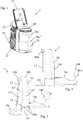
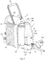
- Figures 1 to 3 illustrates a beverage preparation machine 2 that can be retrofitted with a connecting device 1 shown in Figs 2 to 4 in a manner illustrated in Fig. 5 .
- FIG. 2 and 3 an exemplary connecting device 1 is illustrated in Figs 2 and 3 for connecting a beverage machine 2 (shown in Fig. 1 ) with an external liquid delivery system 3, e.g. a water distribution network, to supply such liquid to said machine 2, in a manner illustrated in Figs 4 and 5 .
- an external liquid delivery system e.g. a water distribution network
- Machine 2 can have an inlet 24 for supplying an ingredient, such as an ingredient contained in a cartridge, to be processed with said liquid in a processing and delivery unit 24,25 to prepare a beverage.
- an ingredient such as an ingredient contained in a cartridge
- Machine 2 may include an outlet 25 for delivering a beverage from a processing and delivery unit 24,25 such as an outlet 25 located above a support 26 for placing a user-recipient, e.g. a cup or a mug, for collecting the beverage delivered by outlet 25.
- a processing and delivery unit 24,25 such as an outlet 25 located above a support 26 for placing a user-recipient, e.g. a cup or a mug, for collecting the beverage delivered by outlet 25.
- Machine 2 can comprise an actuator, such as a handle 23 or a motor, for actuating a beverage processing and delivery unit 24,25 for receiving in and/or evacuating from unit 24,25 an ingredient, such as an ingredient contained in a cartridge.
- an actuator such as a handle 23 or a motor, for actuating a beverage processing and delivery unit 24,25 for receiving in and/or evacuating from unit 24,25 an ingredient, such as an ingredient contained in a cartridge.
- Machine 2 can have a pump for pumping liquid from tank outlet 20d to a beverage delivery outlet 25, optionally via a mixing chamber for mixing said liquid with an ingredient such as an ingredient contained in a cartridge.
- Machine 2 may include a thermal conditioner, such as a heater and/or a cooler, for thermally conditioning said liquid from tank outlet 20d.
- a thermal conditioner such as a heater and/or a cooler, for thermally conditioning said liquid from tank outlet 20d.
- Machine 2 can comprise a machine control unit such as a control unit with a user-interface 27.
- Machine 2 may have an electric connector for supplying power via a power connector 14c,14d to connecting device 1.
- Machine 2 can include a liquid storage tank 20 with an upper opening 20a for supplying liquid into the tank, such as an opening 20a delimited by a rim of tank 20, optionally tank 20 being delimited by a bottom part 20b and a peripheral wall 20c extending from and above bottom part 20b towards opening 20a and/or having a tank outlet 20d for dispensing liquid to a beverage processing and delivery unit 24,25 of machine 2.
- a liquid storage tank 20 with an upper opening 20a for supplying liquid into the tank, such as an opening 20a delimited by a rim of tank 20, optionally tank 20 being delimited by a bottom part 20b and a peripheral wall 20c extending from and above bottom part 20b towards opening 20a and/or having a tank outlet 20d for dispensing liquid to a beverage processing and delivery unit 24,25 of machine 2.
- Machine 2 may comprise a removable tank lid 20', such as a tank lid 20' replaceable by a cover member 16 comprised by connecting device 1.
- tank 20 may have a (solid) tank lid 20' covering opening 20a, lid 20' being removable for filling tank 20.
- lid 20' When connecting device 1 is fixed to tank 20, lid 20' may be removed so that opening 20a remains open or is covered by a cover member 16d that is fixed to connecting device 1 and (re-)movable en bloc with device 1. Hence, tank 20 may nevertheless remain covered when (retro-)fitted with connecting device 1.
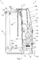
- Connecting device 1 typically has: an inlet 10 for a fluid connection to system 3; an outlet 13 for delivering liquid from external system 3 via inlet 10 to beverage machine 2; a valve arrangement 12a,12b switchable between an open configuration for establishing a fluidic connection between inlet 10 and outlet 13 and a closed configuration for interrupting the fluidic connection, such as a valve arrangement 12a,12b connected to inlet 10 via a fluid connector 11 e.g. a fluid connector 11 fixed to a frame portion 16a of a body 16 of such device 1; and a control unit 14 for switching valve arrangement 12a,12b between its open configuration and its closed configuration.
- a fluid connector 11 e.g. a fluid connector 11 fixed to a frame portion 16a of a body 16 of such device 1
- a control unit 14 for switching valve arrangement 12a,12b between its open configuration and its closed configuration.
- Valve arrangement 12a,12b comprises two or more valves 12a,12b that are in serial fluidic configuration between inlet 10 and outlet 13.
- At least two such valves 12a,12b that are in serial fluidic configuration can be controlled in parallel by control unit 14 to be both simultaneously open for establishing the fluidic connection between inlet 10 and outlet 13 or both simultaneously closed for interrupting the fluidic connection.
- At least two such valves 12a,12b that are in serial fluidic configuration can be controlled separately by control unit 14.
- a first valve 12a e.g. a main valve or a control valve
- a second valve 12b e.g. a back-up or safety valve
- At least one sensor 15c e.g.
- a flowmeter and/or an overfill level sensor can be connected to control unit 14 for sensing an on-going flow of liquid via inlet 10 and outlet 13 after control unit 14 has attempted to switch first valve 12a into its closed configuration and for triggering control unit 14 to switch second valve 12b into its closed configuration.
- Control unit 14 can be arranged to detect a malfunctioning of at least one valve 12a,12b to then indicate to a user such malfunctioning via an indicator 14b and/or block the non-malfunctioning valve in its closed configuration with or without automatically switching-off such device 1.
- Device 1 may include a sensor arrangement 15a,15b connected to control unit 14 that is configured to switch valve arrangement 12a,12b in response to a triggering signal from sensor arrangement 15a,15b.
- Outlet 13 can be configured to deliver liquid from external system 3 into a tank 20 of machine 2 or of such connecting device 1.
- Sensor arrangement 15a,15b may include a low level sensor 15a for detecting a low level 15a' of liquid in tank 20 to generate a triggering signal for switching valve arrangement 12a,12b to the open configuration so as to fill tank 20 with liquid delivered by outlet 13.
- control unit 14 is arranged to switch valve arrangement 12a,12b into the closed configuration:
- Sensor arrangement 15a,15b can have a high level sensor 15b for detecting a high level 15b' of liquid in tank 20 to generate a triggering signal for switching valve arrangement 12a,12b to the closed configuration.
- control unit 14 is configured so as to intermittently read high level sensor 15b, e.g. at time intervals in the range of 1 to 20 or 30 min., and maintain valve arrangement 12a,12b in the closed configuration as long as a high level 15b' of liquid is detected and then temporarily switch valve arrangement 12a,12b into the open configuration until high level 15b' of liquid is again detected whereby high level sensor 15b is read continuously or at short intervals by control unit 14, such as intervals of less than 5 second e.g. intervals in the range of 0.1 to 3 seconds.
- Sensor arrangement 15a,15b may comprise a low level sensor 15a for detecting a low level 15a' of liquid in tank 20 to generate a triggering signal for switching valve arrangement 12a,12b to the open configuration so as to fill tank 20 with liquid delivered by outlet 13 and a high level sensor 15b for detecting a high level 15b' of liquid in tank 20 to generate a triggering signal for switching valve arrangement 12a,12b to the closed configuration.
- control unit 14 is arranged to switch valve arrangement 12a,12b into the closed configuration:
- Further sensor 15c can include a further level sensor connected to control unit 14 and arranged to generate a triggering signal for switching the valve arrangement when a predetermined level above high level 15b' is detected.
- Further sensor 15c can comprise a flowmeter 15c connected to control unit 14 and measuring a volume of liquid that is delivered via outlet 13, the valve arrangement being switched into the closed configuration when the measured volume reaches a predetermined volume, the predetermined volume being optionally user-adjustable, e.g. to adjust to a maximum storage volume of tank 20.
- Sensor arrangement 15a,15b may include at least one of an optical sensor, an electric sensor, e.g. a capacitive sensor, and a float sensor for sensing a float in tank 20.
- Device 1 can have a member 15 bearing sensor arrangement 15a,15.
- Member 15 may extend in a generally upright direction 15' and/or in a generally horizontal direction 15" arranged to generally match a wall 20c of machine 2, such as a peripheral wall 20c of tank 20 of machine 2, along (a) corresponding direction(s) 20c',20c", when such device 1 is fixed to tank 20.
- Member 15 can extend in a generally upright direction in a manner as to generally extend along thank wall 20c inside or outside tank 20 of machine 2, when such device 1 is fixed to tank 20.
- Member 15 may form a wall 15 of a body 16 of connecting device 1.
- Member 15 can be formed by a PCB which interfaces at least one or two sensor(s) 15a,15b of sensor arrangement 15a,15b to control unit 14.
- control unit 14 is connected to at least one of: a power source via a power connector 14c,14d; and a user interface 14a,14b such as an interface comprising a and/or reset switch 14a (e.g. an on/off switch and/or a switch for resetting device 1) 14a and/or a control indicator e.g. a control light 14b.
- the power source may be provided by beverage preparation machine 2 itself or may be external to device 1 and to machine 2, for instance the mains.
- Power connector 14c,14d may include an electric cable 14c and a plug 14d.
- Power connector 14c,14d may include a voltage transformer, e.g. within plug 14d or on control unit 14.
- Device 1 may include an assembly arrangement 16c,16d for reversibly or irreversibly fixing connecting device 1 to machine 2, e.g. to a tank 20 thereof.
- such device 1 forms a user-removable accessory 1 fixed to tank 20 so that outlet 13 is positioned for delivering liquid into tank 20 via an upper opening 20a of tank 20.
- Assembly arrangement 16c,16d can be configured for fixing such device 1 to tank 20 so that sensor arrangement 15a,15b extends inside tank 20 via a tank opening 20a or is located adjacent a peripheral tank wall 20c externally to the tank 20, so as to generate a triggering signal when the liquid reaches a predetermined level 15a',15b' in tank 20.
- the connecting device may be connected to and use sensors that are integrated in the beverage machine to monitor the tank.
- Device 1 can have a body 16 and an overhanging arm 16b arranged to extend over a tank opening 20a of tank 20 and optionally into tank 20 via opening 20a, overhanging arm 16 being formed of or holding at least one of outlet 13 and the sensor arrangement.
- Overhanging arm 16b may include a connecting portion 16e for connecting a cover member 16d that is configured to cover opening 20a of tank 20.
- connecting portion 16e for connecting a cover member 16d that is configured to cover opening 20a of tank 20.
- outlet 13 and/or sensor arrangement extends through connecting portion 16e or forms connecting portion or is integral with the connecting portion and cover member 16d.
- Device 1 can comprise a cover member 16d that is configured to close a tank opening 20a of tank 20, cover member 16d delimiting a passage 16e, such as a through hole, through which outlet 13 extends or through which outlet can deliver liquid into tank 20.
- sensor arrangement 15a,15b extends through this passage or through a different passage delimited by cover member into the tank or is confined outside tank 20.
- Cover member 16d may include an assembly arrangement 16f for reversibly assembling cover member 16d to at least one of tank 20, such as to a rim delimiting tank opening 20a, and/or to a main machine body 22 of beverage machine 2 e.g. by being hooked to main machine body 22.
- Device 1 can have a device body 16 and an assembly arrangement 16c;16b,16d,16e,16f for reversibly or irreversibly assembling device body 16 to tank 20 and/or to a main machine body 22 of beverage machine 2.
- the assembly arrangement can include a lower assembly arrangement 16c, such as a foot, for reversibly or irreversibly assembling the device body 16 to a lower part 20b of tank 20 and/or to a lower part of main machine body 22.
- lower assembly arrangement 16c has a platform projecting from a bottom part of device body 16 and/or extends under outlet 13.
- the assembly arrangement may have an upper assembly arrangement 16b,16d,16e,16f, such as a top, for reversibly or irreversibly assembling device body 16 to an upper part 20a of tank 20 and/or to an upper part of main machine body 22.
- upper assembly arrangement 16b,16d,16e,16f includes an arm 16b projecting from a top part of device body 16 and/or extending above outlet 13, such as an arm forming or fixed to a cover member 20d.
- the assembly arrangement may comprise a first assembly arrangement 16c, such as a lower assembly arrangement e.g. a foot, and a second assembly arrangement 16b,16d,16e,16f, e.g. an upper assembly arrangement, which can be reversibly or irreversibly fixed to machine 2, e.g. to tank 20, by fastening first and second arrangements 16b,16c,16d,16e,16f to one another by a fixing arrangement 16bc.
- Fixing arrangement 16bc may include any connector that reversibly or irreversibly fixes directly or indirectly connecting device 1 to machine 2, e.g. a machine's tank 20 and/or machine's main body 22, such as a mechanical or physical or chemical connector, e.g.
- first and second arrangements 16b,16c,16d,16e,16f are fixed together.
- Device body 16 can be made of a first part 16' and a second part 16", first part 16' comprising first assembly arrangement 16c and second part 16" comprising second assembly arrangement 16b,16d,16e,16f, first and second assembly arrangements 16c;16b,16d,16e,16f being reversibly or irreversibly fixed to machine 2 by assembling first and second parts 16',16" together by fixing arrangement 16bc.
- At least one of first and second parts 16',16" may include an outer housing 161',161" by which it is assembled to the other part.
- each part 16',16" has an outer housing 161',161" whereby parts 16',16" are assembled together via their respective outer housings 161',161".
- first and second parts 16',16" can comprise inlet 10, outlet 13, valve arrangement 12a,12b and control unit 14.
- inlet 10 and/or outlet 13 extend(s) through the other part 16' of first and second parts 16',16" such as through an opening 16c' delimited by a housing 161' of other part 16', e.g. an opening delimited by a housing 161' of first part 16' and a housing of the second part 16".
Landscapes
- Engineering & Computer Science (AREA)
- Food Science & Technology (AREA)
- Devices For Dispensing Beverages (AREA)
Claims (15)
- Verbindungsvorrichtung (1) zum Verbinden einer Getränkemaschine (2) mit einem externen Flüssigkeitsabgabesystem (3), zum Beispiel einem Wasserverteilungsnetz, um die Flüssigkeit der Maschine (2) zuzuführen, wobei die Verbindungsvorrichtung (1) aufweist:- einen Einlass (10) für eine Fluidverbindung zu dem externen System (3);- einen Auslass (13) zum Abgeben von Flüssigkeit aus dem externen System (3) über den Einlass (10) an die Getränkemaschine (2);- eine Ventilanordnung (12a, 12b), die zwischen einer offenen Konfiguration zum Herstellen einer Fluidverbindung zwischen dem Einlass (10) und dem Auslass (13) und einer geschlossenen Konfiguration zum Unterbrechen der Fluidverbindung umschaltbar ist, wie etwa eine Ventilanordnung (12a, 12b), die mit dem Einlass (10) über einen Fluidverbinder (11) verbunden ist, z. B. einen Fluidverbinder (11), der an einem Rahmenabschnitt (16a) eines Körpers (16) der Vorrichtung (1) fixiert ist; und- eine Steuereinheit (14) zum Umschalten der Ventilanordnung (12a, 12b) zwischen ihrer offenen Konfiguration und ihrer geschlossenen Konfiguration,dadurch gekennzeichnet, dass die Ventilanordnung (12b, 12a) zwei oder mehrere Ventile (12b, 12a) umfasst, die sich in einer Reihenfluidkonfiguration zwischen dem Einlass (10) und dem Auslass (13) befinden, wobei mindestens zwei Ventile (12b, 12a), die sich in Reihenfluidkonfiguration befinden, durch die Steuereinheit (14) gesteuert werden:- parallel, sodass sie beide gleichzeitig offen sind, um die Fluidverbindung zwischen dem Einlass (10) und dem Auslass (13) herzustellen, oder beide gleichzeitig geschlossen sind, um die Fluidverbindung zu unterbrechen; oder- separat, sodass ein erstes Ventil (12a) der Ventile (12a, 12b) offen oder geschlossen ist, um die Fluidverbindung zwischen dem Einlass (10) und dem Auslass (13) herzustellen oder zu unterbrechen, wie es zum Zuführen von Flüssigkeit zu der Maschine erforderlich ist, und sodass ein zweites Ventil (12b) der Ventile (12a, 12b) offen ist, solange sich das erste Ventil (12a) öffnet und schließt, wenn es durch die Steuereinheit (14) gesteuert wird, und geschlossen ist, wenn das erste Ventil (12a) nicht richtig funktioniert, wobei wahlweise mindestens ein Sensor (15c), z. B. ein Durchflussmesser und/oder ein Überfüllungspegelsensor, mit der Steuereinheit (14) verbunden ist, um ein im Gange befindliches Fließen von Flüssigkeit über den Einlass (10) und den Auslass (13) zu erfassen, nachdem die Steuereinheit (14) versucht hat, das erste Ventil (12a) in seine geschlossene Konfiguration umzuschalten, und um auszulösen, dass die Steuereinheit (14) das zweite Ventil (12b) in seine geschlossene Konfiguration umschaltet,wobei die Steuereinheit (14) wahlweise dazu eingerichtet ist, eine Störung von mindestens einem Ventil (12a, 12b) zu erkennen, um die Störung dann einem Benutzer über eine Anzeige (14b) anzuzeigen und/oder das nicht gestörte Ventil mit oder ohne automatisches Ausschalten der Vorrichtung (1) in seiner geschlossenen Konfiguration zu blockieren.
- Vorrichtung nach Anspruch 1, die eine Sensoranordnung (15a, 15b) umfasst, die mit der Steuereinheit (14) verbunden ist, die dazu konfiguriert ist, die Ventilanordnung (12a, 12b) als Reaktion auf ein Auslösesignal von der Sensoranordnung (15a, 15b) umzuschalten.
- Vorrichtung nach Anspruch 2, wobei der Auslass (13) dazu konfiguriert ist, Flüssigkeit von dem externen System (3) in einen Tank (20) der Maschine (2) oder der Verbindungsvorrichtung (1) abzugeben, wobei die Sensoranordnung (15a, 15b) umfasst:- einen Niedrigpegelsensor (15a) zum Erkennen eines niedrigen Pegels (15a') an Flüssigkeit in dem Tank (20), um ein Auslösesignal zum Umschalten der Ventilanordnung (12a, 12b) in die offene Konfiguration zu erzeugen, um so den Tank (20) mit Flüssigkeit, die durch den Auslass (13) abgegeben wird, zu füllen, wobei die Steuereinheit (14) wahlweise dazu eingerichtet ist, die Ventilanordnung (12a, 12b) in die geschlossene Konfiguration umzuschalten:- wenn eine vorbestimmte Zeitdauer nach einem Umschalten der Ventilanordnung (12a, 12b) in die offene Konfiguration abgelaufen ist, wobei die vorbestimmte Zeitdauer wahlweise von einem Benutzer einstellbar ist, um z. B. eine Flussrate von Flüssigkeit, die von dem externen Abgabesystem (3) zugeführt wird, einzustellen und/oder um ein maximales Speichervolumen des Tanks (20) einzustellen;
und/oder- wenn ein weiterer Pegelsensor, der einen Überfüllungspegel über dem hohen Pegel (15b') erkennt, ein Auslösesignal zum Umschalten der Ventilanordnung erzeugt, oder wenn ein vorbestimmtes Volumen an Flüssigkeit, das durch einen weiteren Sensor (15c), der mit der Steuereinheit (14) verbunden ist, gemessen wurde, über den Auslass (13) abgegeben wurde, wobei das vorbestimmte Volumen wahlweise von einem Benutzer einstellbar ist, um z. B. ein maximales Speichervolumen des Tanks (20) einzustellen;oder- einen Hochpegelsensor (15b) zum Erkennen eines hohen Pegels (15b') an Flüssigkeit in dem Tank (20), um ein Auslösesignal zum Umschalten der Ventilanordnung (12a, 12b) in die geschlossene Konfiguration zu erzeugen, wobei die Steuereinheit (14) wahlweise dazu konfiguriert ist, den Hochpegelsensor (15b) intermittierend zu lesen, z. B. in Zeitintervallen in dem Bereich von 1 bis 20 oder 30 min, und die Ventilanordnung (12b, 12a) so lange in der geschlossenen Konfiguration zu halten, wie ein hoher Pegel (15b') an Flüssigkeit erkannt wird, und dann die Ventilanordnung (12b, 12a) vorübergehend in die offene Konfiguration umzuschalten, bis der hohe Pegel (15b') an Flüssigkeit wieder erkannt wird, wobei der Hochpegelsensor (15b) ununterbrochen oder in kurzen Intervallen durch die Steuereinheit (14) gelesen wird, wie etwa in Intervallen von weniger als 5 Sekunden, z. B. Intervallen in dem Bereich von 0,1 bis 3 Sekunden;
oder- einen Niedrigpegelsensor (15a) zum Erkennen eines niedrigen Pegels (15a') an Flüssigkeit in dem Tank (20), um ein Auslösesignal zum Umschalten der Ventilanordnung (12a, 12b) in die offene Konfiguration zu erzeugen, um so den Tank (20) mit Flüssigkeit, die durch den Auslass (13) abgegeben wird, zu füllen, und einen Hochpegelsensor (15b) zum Erkennen eines hohen Pegels (15b') an Flüssigkeit in dem Tank (20), um ein Auslösesignal zum Umschalten der Ventilanordnung (12a, 12b) in die geschlossene Konfiguration zu erzeugen, wobei die Steuereinheit (14) wahlweise auch dazu eingerichtet ist, die Ventilanordnung (12a, 12b) in die geschlossene Konfiguration umzuschalten:- wenn eine vorbestimmte Zeitdauer nach einem Umschalten der Ventilanordnung (12a, 12b) in die offene Konfiguration abgelaufen ist, wobei die vorbestimmte Zeitdauer wahlweise von einem Benutzer einstellbar ist, um z. B. eine Flussrate von Flüssigkeit, die von dem externen Abgabesystem (3) zugeführt wird, einzustellen und/oder um ein maximales Speichervolumen des Tanks (20) einzustellen; und/oder- wenn ein weiterer Sensor (15c) ein Signal an die Steuereinheit (14) bereitstellt, das anzeigt, dass der hohe Pegel (15b') überschritten wurde. - Vorrichtung nach Anspruch 3, wobei der weitere Sensor (15c) umfasst:- einen weiteren Pegelsensor, der mit der Steuereinheit (14) verbunden ist und angeordnet ist, um ein Auslösesignal zum Umschalten der Ventilanordnung zu erzeugen, wenn ein vorbestimmter Pegel oberhalb des hohen Pegels (15b') erkannt wird; und/oder- einen Durchflussmesser (15c), der mit der Steuereinheit (14) verbunden ist und ein Volumen an Flüssigkeit misst, das über den Auslass (13) abgegeben wird, wobei die Ventilanordnung in die geschlossene Konfiguration umgeschaltet wird, wenn das gemessene Volumen ein vorbestimmtes Volumen erreicht, wobei das vorbestimmte Volumen wahlweise von einem Benutzer einstellbar ist, um z. B. ein maximales Speichervolumen des Tanks (20) einzustellen.
- Vorrichtung nach Anspruch 3 oder 4, wobei die Sensoranordnung (15a, 15b) mindestens einen von einem optischen Sensor, einem elektrischen Sensor, z. B. einem kapazitiven Sensor, und einem Schwimmsensor zum Erfassen eines Schwimmers in dem Tank (20) umfasst.
- Vorrichtung nach einem der Ansprüche 2 bis 5, die ein Element (15) umfasst, das die Sensoranordnung (15a, 15b) trägt, wobei das Element (15) wahlweise eines oder mehrere der folgenden Merkmale a) bis d) aufweist:a) das Element (15) erstreckt sich in einer in Allgemeinen senkrechten Richtung (15') und/oder in einer im Allgemeinen horizontalen Richtung (15"), die dazu eingerichtet ist, im Allgemeinen zu einer Wand (20c) der Maschine (2), wie etwa einer Umfangswand (20c) eines Tanks (20) der Maschine (2), entlang (einer) entsprechenden Richtung(en) (20c', 20c") zu passen, wenn die Vorrichtung (1) an dem Tank (20) fixiert ist;b) das Element (15) erstreckt sich in einer im Allgemeinen senkrechten Richtung, sodass es sich im Allgemeinen entlang der Tankwand (20c) innerhalb oder außerhalb eines Tanks (20) der Maschine erstreckt, wenn die Vorrichtung (1) an dem Tank (20) fixiert ist;c) das Element (15) bildet eine Wand (15) eines Körpers (16) der Vorrichtung (1);d) das Element (15) ist durch eine PCB gebildet, die eine Schnittstelle der Steuereinheit (14) mit mindestens einem oder zwei Sensor(en) (15a, 15b) der Sensoranordnung (15a, 15b) bildet.
- Vorrichtung nach einem der vorstehenden Ansprüche, wobei die Steuereinheit (14) mit mindestens einem verbunden ist von: einer Stromquelle über einen Stromverbinder (14c, 14d); und einer Benutzerschnittstelle (14a, 14b), wie etwa einer Schnittstelle, umfassend einen Leistungs- und/oder Rücksetzschalter (14a) und/oder einen Steuerindikator, z. B. eine Steuerleuchte (14b).
- Vorrichtung nach einem der vorstehenden Ansprüche, die ferner eine Montageanordnung (16c, 16d) zum reversiblen oder irreversiblen Fixieren der Verbindungsvorrichtung (1) an der Maschine (2), z. B. an einem Tank (20) davon, umfasst, wobei die Vorrichtung (1) wahlweise ein von einem Benutzer entfernbares Zubehör (1) bildet, das an dem Tank (20) fixiert ist, sodass der Auslass (13) zum Abgeben von Flüssigkeit in den Tank (20) über eine obere Öffnung (20a) des Tanks (20) positioniert ist.
- Vorrichtung nach Anspruch 8, wobei die Montageanordnung (16c, 16d) dazu konfiguriert ist, die Vorrichtung (1) so an dem Tank (20) zu fixieren, dass sich die Sensoranordnung (15a, 15b) über eine Tanköffnung (20a) in das Innere des Tanks (20) erstreckt oder sich benachbart einer Tankumfangswand (20c) außerhalb des Tanks (20) befindet, um so ein Auslösesignal zu erzeugen, wenn die Flüssigkeit einen vorbestimmten Pegel (15a', 15b') in dem Tank (20) erreicht.
- Vorrichtung nach Anspruch 8 oder 9, die einen Körper (16) und einen überhängenden Arm (16b) umfasst, der dazu eingerichtet ist, sich über eine Tanköffnung (20a) des Tanks (20) und wahlweise über die Öffnung (20a) in den Tank (20) zu erstrecken, wobei der überhängende Arm (16) aus mindestens einem von dem Auslass (13) und der Sensoranordnung gebildet ist oder mindestens eines davon hält.
- Vorrichtung nach Anspruch 10, wobei der überhängende Arm (16b) einen Verbindungsabschnitt (16e) zum Verbinden eines Abdeckelements (16d) umfasst, das dazu konfiguriert ist, die Öffnung (20a) des Tanks (20) abzudecken, wobei sich wahlweise der Auslass (13) und/oder die Sensoranordnung durch den Verbindungsabschnitt (16e) erstrecken oder den Verbindungsabschnitt bilden oder einstückig mit dem Verbindungsabschnitt und dem Abdeckelement (16d) sind.
- Vorrichtung nach einem der Ansprüche 8 bis 11, die ein Abdeckelement (16d) umfasst, das dazu konfiguriert ist, eine Tanköffnung (20a) des Tanks (20) zu schließen, wobei das Abdeckelement (16d) einen Durchlass (16e) begrenzt, wie etwa eine Durchgangsöffnung, durch den sich der Auslass (13) erstreckt oder durch den der Auslass Flüssigkeit in den Tank (20) abgeben kann, wobei sich die Sensoranordnung (15a, 15b) wahlweise durch den Durchlass oder durch einen anderen Durchlass, der von dem Abdeckelement begrenzt wird, in den Tank erstreckt oder außerhalb des Tanks (20) eingeschlossen ist.
- Vorrichtung nach Anspruch 11 oder 12, wobei das Abdeckelement (16d) eine Montageanordnung (16f) zum reversiblen Montieren des Abdeckelements (16d) an mindestens einem von dem Tank (20), wie etwa an einem Rand, der die Tanköffnung (20a) begrenzt, und/oder an einem Hauptmaschinenkörper (22) der Getränkemaschine (2), z. B. durch Einhaken an dem Hauptmaschinenkörper (22), umfasst.
- Vorrichtung nach einem der Ansprüche 8 bis 13, die einen Vorrichtungskörper (16) und eine Montageanordnung (16c; 16b, 16d, 16e, 16f) zum reversiblen oder irreversiblen Montieren des Vorrichtungskörpers (16) an dem Tank (20) und/oder an einem Hauptmaschinenkörper (22) der Getränkemaschine (2) umfasst, wie etwa:- eine untere Montageanordnung (16c), wie etwa einen Fuß, zum reversiblen oder irreversiblen Montieren des Vorrichtungskörpers (16) an einem unteren Teil (20b) des Tanks (20) und/oder an einem unteren Teil des Hauptmaschinenkörpers (22), wobei die untere Montageanordnung (16c) wahlweise eine Plattform umfasst, die von einem Bodenteil des Vorrichtungskörpers (16) vorspringt und/oder sich unter dem Auslass (13) erstreckt; und/oder- eine obere Montageanordnung (16b, 16d, 16e, 16f), wie etwa ein Oberteil, zum reversiblen oder irreversiblen Montieren des Vorrichtungskörpers (16) an einem oberen Teil (20a) des Tanks (20) und/oder an einem oberen Teil des Hauptmaschinenkörpers (22), wobei die obere Montageanordnung (16b, 16d, 16e, 16f) wahlweise einen Arm (16b) umfasst, der von einem oberen Teil des Vorrichtungskörpers (16) vorspringt und/oder sich über dem Auslass (13) erstreckt, wie etwa einen Arm, der ein Abdeckelement (20d) bildet oder daran fixiert ist; und/oder- eine erste Montageanordnung (16c), wie etwa eine untere Montageanordnung, z. B. einen Fuß, und eine zweite Montageanordnung (16b, 16d, 16e, 16f), z. B. eine obere Montageanordnung, die reversibel oder irreversibel an der Maschine (2) fixiert werden können, z. B. an dem Tank (20) und/oder Hauptmaschinenkörper (22), durch Aneinanderbefestigen der ersten und der zweiten Anordnungen (16b, 16c, 16d, 16e, 16f) durch eine Fixieranordnung (16bc), die einen beliebigen Verbinder, der die Verbindungsvorrichtung (1) reversibel oder irreversibel direkt oder indirekt an der Maschine (2), z. B. einem Maschinentank (20) und/oder Maschinenhauptkörper (22), fixiert, wie etwa einen mechanischen oder physischen oder chemischen Verbinder, einschließen kann, z. B. eines oder mehrere von Haken, Clips, Schnappverschlüssen, Klemmen, Nieten, Schrauben, Nägeln, Reibungsbefestigern, geometrischen Befestigern, magnetischen Verbindern, Klebeflächen und Schweißflächen, wahlweise wenn die ersten und zweiten Anordnungen (16b, 16c, 16d, 16e, 16f) aneinander fixiert sind:- wobei sie sich über zwei Extremitäten der Maschine (2), z. B. über den Tank (20) und/oder Hauptmaschinenkörper (22), erstrecken, um eine Klemme zu bilden, die an der Maschine (2), z. B. an dem Tank (20) und/oder Hauptmaschinenkörper (22), gesichert ist, wobei die zwei Extremitäten beispielsweise ein Oberteil und ein Bodenteil der Maschine (2), z. B. des Tanks (20) und/oder Hauptmaschinenkörpers (22), bilden; und/oder- wobei sie sich außerhalb über und um die Maschine (2), z. B. außerhalb über und um den Tank (20) und/oder den Hauptmaschinenkörper (22), erstrecken und wahlweise durch eine Öffnung (20a) des Tanks (20) und/oder des Hauptmaschinenkörpers (22) verlaufen; und/oder- wobei sie zwischen sich eine Öffnung (16c') begrenzen, durch die das externe System (3) mit dem Einlass (10) verbunden wird.
- Getränkemaschine (2), umfassend eine Verbindungsvorrichtung (1) nach einem der vorstehenden Ansprüche, wobei die Vorrichtung (1) dazu eingerichtet ist, die Maschine (2) mit einem externen Flüssigkeitsabgabesystem (3), z. B. einem Wasserverteilungsnetz, zu verbinden, um die Flüssigkeit der Maschine (2) zuzuführen, wobei die Maschine wahlweise eines oder mehrere aufweist von:- einem Einlass (24) zum Zuführen eines Inhaltsstoffs, wie etwa eines Inhaltsstoffs, der in einer Kapsel enthalten ist, zum Verarbeiten mit der Flüssigkeit in einer Verarbeitungs- und Abgabeeinheit (24, 25), um ein Getränk zuzubereiten;- einem Auslass (25) zum Abgeben eines Getränks aus einer Verarbeitungs- und Abgabeeinheit (24, 25), wie etwa einem Auslass (25), der sich über einem Träger (26) zum Platzieren eines Benutzerbehälters, z. B. einer Tasse oder eines Bechers, zum Auffangen des Getränks, das durch den Auslass (25) abgegeben wird, befindet;- einem Betätigungselement, wie etwa einem Griff (23) oder einem Motor, zum Betätigen einer Getränkeverarbeitungs- und -abgabeeinheit (24, 25) zum Aufnehmen und/oder Entleeren eines Inhaltsstoffs, wie etwa eines Inhaltsstoffs, der in einer Kapsel enthalten ist, in die/aus der Einheit (24, 25);- einer Pumpe zum Pumpen der Flüssigkeit von dem Tankauslass (20d) zu einem Getränkeabgabeauslass (25), wahlweise über eine Mischkammer zum Mischen der Flüssigkeit mit einem Inhaltsstoff, wie etwa einem Inhaltsstoff, der in einer Kapsel enthalten ist;- einem Wärmekonditionierer, wie etwa einer Heiz- und/oder Kühleinrichtung, zur Wärmekonditionierung der Flüssigkeit aus dem Tankauslass (20d);- einer Maschinensteuereinheit, wie etwa einer Steuereinheit mit einer Benutzerschnittstelle (27);- einem elektrischen Verbinder zum Zuführen von Leistung über einen Leistungsverbinder (14c, 14d) an die Verbindungsvorrichtung (1);- einem Flüssigkeitsspeichertank (20) mit einer oberen Öffnung (20a) zum Zuführen von Flüssigkeit in den Tank, wie etwa einer Öffnung (20a), die durch einen Rand des Tanks (20) begrenzt ist, wobei der Tank (20) wahlweise durch ein Bodenteil (20b) und eine Umfangswand (20c) begrenzt ist, die sich von und über dem Bodenteil (20b) in Richtung der Öffnung (20a) erstreckt, und/oder einen Tankauslass (20d) zum Abgeben von Flüssigkeit an eine Getränkeverarbeitungs- und -abgabeeinheit (24, 25) der Maschine (2) aufweist; und- einem entfernbaren Tankdeckel (20'), wie etwa einem Tankdeckel (20'), der durch ein Abdeckelement (16) ersetzbar ist, das die Verbindungsvorrichtung (1) umfasst.
Applications Claiming Priority (2)
| Application Number | Priority Date | Filing Date | Title |
|---|---|---|---|
| EP14176240 | 2014-07-09 | ||
| PCT/EP2015/065409 WO2016005348A1 (en) | 2014-07-09 | 2015-07-07 | Device for connecting a beverage machine to a distribution network with safe flow interruption |
Publications (2)
| Publication Number | Publication Date |
|---|---|
| EP3166455A1 EP3166455A1 (de) | 2017-05-17 |
| EP3166455B1 true EP3166455B1 (de) | 2020-09-30 |
Family
ID=51167697
Family Applications (1)
| Application Number | Title | Priority Date | Filing Date |
|---|---|---|---|
| EP15734186.8A Active EP3166455B1 (de) | 2014-07-09 | 2015-07-07 | Vorrichtung zum verbinden einer getränkemaschine mit einem verteilungsnetz mit sicherer strömungsunterbrechung |
Country Status (4)
| Country | Link |
|---|---|
| EP (1) | EP3166455B1 (de) |
| ES (1) | ES2828253T3 (de) |
| PT (1) | PT3166455T (de) |
| WO (1) | WO2016005348A1 (de) |
Families Citing this family (4)
| Publication number | Priority date | Publication date | Assignee | Title |
|---|---|---|---|---|
| CA3108829A1 (en) | 2018-08-09 | 2020-02-13 | Societe Des Produits Nestle S.A. | Easily insertable cup support |
| CN112689466B (zh) | 2018-09-27 | 2023-09-05 | 雀巢产品有限公司 | 饮料机的自适应服务单元 |
| EP3628195A1 (de) | 2018-09-27 | 2020-04-01 | Société des Produits Nestlé S.A. | Getränkeherstellungsmaschine mit behältererkennung |
| CA3233465A1 (en) | 2021-10-13 | 2023-04-20 | Laurent LAGOUCHE | Ergonomic beverage machine |
Citations (1)
| Publication number | Priority date | Publication date | Assignee | Title |
|---|---|---|---|---|
| WO2007046702A2 (en) * | 2005-10-20 | 2007-04-26 | Bravilor Holding B.V. | Device for preparing hot water and coffee machine provided with such a device |
Family Cites Families (83)
| Publication number | Priority date | Publication date | Assignee | Title |
|---|---|---|---|---|
| NL8601122A (nl) * | 1986-05-01 | 1987-12-01 | Verheijen Bv | Inrichting voor het leveren van heet water. |
| FR2721381B1 (fr) | 1994-06-20 | 1996-08-02 | Seb Sa | Dispositif de production d'eau chaude ou de vapeur. |
| US6459854B1 (en) | 2000-01-24 | 2002-10-01 | Nestec S.A. | Process and module for heating liquid |
| FR2806606B1 (fr) | 2000-03-24 | 2002-10-25 | Moulinex Sa | Machine a cafe electrique avec reservoir d'eau pivotant |
| DK1153561T3 (da) | 2000-05-09 | 2005-11-14 | Nestle Sa | Indretning til udtrækning af en substans |
| DK1208782T3 (da) | 2000-11-28 | 2004-12-13 | Nestle Sa | Perkolationsindretning |
| DE20105672U1 (de) | 2001-03-31 | 2001-09-13 | Eugster/Frismag Ag, Romanshorn | Espressobrüheinrichtung |
| AU2002242670B2 (en) | 2002-01-10 | 2007-01-25 | Societe Des Produits Nestle S.A. | Automatic device for the extraction of a substance |
| DK1380243T3 (da) | 2002-07-12 | 2008-08-25 | Nestec Sa | Indretning til opvarmning af en væske |
| SI1444932T1 (sl) | 2003-02-07 | 2006-04-30 | Nestec Sa | Ekstrakcijski modul z lineranim zapiranjem za pripravo pod tlakom pijace iz kapsule |
| DE20302410U1 (de) | 2003-02-13 | 2004-06-24 | Nestec S.A. | Kapselmagazineinheit mit Kapselmagazineinheitaufnahmeeinrichtung, insbesondere einer Espressomaschine |
| NL1023023C2 (nl) * | 2003-03-26 | 2004-09-30 | Bravilor Holding Bv | Inrichting voor het bereiden van heet water. |
| EP1495702A1 (de) | 2003-07-10 | 2005-01-12 | Nestec S.A. | Vorrichtung zur Extraktion einer Kartusche |
| PL1686879T3 (pl) | 2003-11-22 | 2008-03-31 | Nestec Sa | Ruchome lub przenośne urządzenie ze źródłem sprężonego gazu do przygotowywania napojów lub podobnych produktów |
| US7165488B2 (en) | 2003-12-12 | 2007-01-23 | Keurig, Incorporated | Brew chamber for a single serve beverage brewer |
| EP1634520A1 (de) | 2004-09-13 | 2006-03-15 | Nestec S.A. | Vorrichtung zur Heizung einer Flüssigkeit und Verfahren zum Erhitzen einer Flüssigkeit |
| PT1656863E (pt) | 2004-11-11 | 2011-03-22 | Nestec Sa | Cabeça de mistura de limpeza automática para produção de uma mistura à base de leite e máquinas de produção de bebidas compreendendo esta cabeça de mistura |
| BRPI0608648A2 (pt) | 2005-03-29 | 2010-01-19 | Nestec Sa | mÁquina de distribuiÇço de bebidas independente |
| DE602005007475D1 (de) | 2005-06-07 | 2008-07-24 | Nestec Sa | Getränkemaschine mit Auffangwanne für Behälter unterschiedlicher Höhe |
| EP1900312B1 (de) | 2005-09-20 | 2010-06-09 | Nestec S.A. | Getränkeherstellungsvorrichtung auf Thermoblockbasis mit einer Braukammer |
| ES2317123T5 (es) | 2005-09-27 | 2017-05-05 | Nestec S.A. | Módulo de extracción para un dispositivo de producción de bebidas a partir de cápsulas |
| DE202006002678U1 (de) | 2006-02-17 | 2006-04-20 | Eugster/Frismag Ag | Kaffeemaschine zur Zubereitung eines Kaffeegetränks mittels abgepackter, vorportionierter Kaffeepouches |
| FR2898028B1 (fr) | 2006-03-01 | 2008-05-16 | Seb Sa | Machine a infuser comprenant un dispositif d'ejection du produit infuse |
| US7513192B2 (en) | 2006-03-23 | 2009-04-07 | Keurig, Incorporated | Beverage forming device with opening/closing mechanism for a beverage cartridge receiver |
| ATE556630T1 (de) | 2006-05-24 | 2012-05-15 | Nestec Sa | Brühvorrichtung für kapsel mit verschlussmechanismus mit variablem übersetzungsverhältnis |
| ES2359577T3 (es) | 2006-06-09 | 2011-05-24 | Nestec S.A. | Dispositivo modular para la producción de bebidas con estación receptora. |
| EP1867260B1 (de) | 2006-06-16 | 2010-05-26 | Nestec S.A. | Getränkeautomat mit Auflagesystem und Tropffänger für Behälter verschiedener Grössen |
| ATE435604T1 (de) | 2006-07-11 | 2009-07-15 | Nestec Sa | MASCHINE ZUR ZUBEREITUNG VON GETRÄNKEN MIT FUNKTIONSVORRICHTUNG UND FUßAUFBAU |
| PT1992263E (pt) | 2007-05-16 | 2012-01-05 | Nestec Sa | Módulo de produção de bebidas e método de implementação do módulo de produção de bebidas |
| CN201076369Y (zh) | 2007-07-24 | 2008-06-25 | 宁波圣开纳电器有限公司 | 一种可用自来水供水的咖啡机 |
| EP2027798A1 (de) | 2007-08-20 | 2009-02-25 | Nestec S.A. | Getränkeproduktionsmodul und Verfahren für den Betrieb eines Getränkeproduktionsmoduls |
| CL2008002963A1 (es) | 2007-10-04 | 2010-01-22 | Nestec Sa | Dispositivo calentador para una maquina para la preparacion de alimento liquido o bebida, que comprende una unidad termica con una masa metalica, a traves de la cual circula el liquido, y acumula calor y lo suministra al liquido, y tiene uno o mas componentes electricos asegurados en forma rigida a la unidad termica; y maquina. |
| BRPI0818185B1 (pt) | 2007-10-04 | 2020-04-07 | Nestec Sa | máquina de bebida e combinação de uma máquina de bebida e uma cápsula |
| EP2218374B1 (de) | 2007-10-04 | 2017-12-27 | Nestec S.A. | Getränkezubereitungseinheit |
| EP2070454B1 (de) | 2007-12-12 | 2015-07-15 | Nestec S.A. | Modulare Herstellung von Getränkeherstellungsmaschinen |
| BRPI0821188B1 (pt) | 2007-12-12 | 2019-04-16 | Nestec S.A. | Receptáculo de cápsula ou saco usado para máquinas de alimento líquido ou bebida |
| EP2082669A2 (de) | 2008-01-25 | 2009-07-29 | Nestec S.A. | Hybridvorrichtung für die Getränkezubereitung |
| RU2463245C2 (ru) | 2008-05-08 | 2012-10-10 | Нестек С.А. | Средство для установки уровня наполнения чашки, используемое с устройством для разлива напитков |
| BRPI0912311A2 (pt) | 2008-05-28 | 2015-10-13 | Nestec Sa | bomba para dispositivos de preparação de bebidas líquidas. |
| RU2544762C2 (ru) | 2008-07-09 | 2015-03-20 | Нестек С.А. | Эргономичный экранный интерфейс для машины приготовления напитков |
| US8479643B2 (en) | 2008-07-14 | 2013-07-09 | Nestec S.A. | Water circulation system for a beverage preparation device |
| RU2517804C2 (ru) | 2008-08-08 | 2014-05-27 | Нестек С.А. | Машина для приготовления напитков с ручкой для переноски, имеющая адаптируемый внешний вид и содержащая сменные боковые панели |
| WO2010037806A1 (en) | 2008-10-03 | 2010-04-08 | Nestec S.A. | User-friendly interface for a beverage machine |
| EP2228633B1 (de) | 2009-03-10 | 2017-07-05 | Nestec S.A. | Optischer Füllstandssensor für eine Getränkemaschine |
| US8863648B2 (en) | 2009-03-23 | 2014-10-21 | Nestec S.A. | Pump mount in a beverage preparation machine |
| US8387455B1 (en) | 2009-03-26 | 2013-03-05 | Food Equipment Technologies Company, Inc. | Beverage dispenser with capacitive level sensor and display and method |
| AU2010244366A1 (en) | 2009-05-06 | 2011-12-08 | Nestec S.A. | Beverage machines with simplified servicing |
| ES2458415T3 (es) | 2009-08-19 | 2014-05-05 | Nestec S.A. | Modo de puesta en marcha de fácil uso para usuarios de una máquina para la preparación de bebidas |
| JP2013503667A (ja) | 2009-09-02 | 2013-02-04 | ネステク ソシエテ アノニム | ネットワーク用飲料マシン |
| US9138096B2 (en) | 2009-09-09 | 2015-09-22 | Nestec S.A. | Beverage machine in a network |
| PT2521471E (pt) | 2010-01-06 | 2014-04-04 | Nestec Sa | Reservatório de água à prova de vibrações de uma máquina de bebidas |
| ES2496767T5 (es) | 2010-01-21 | 2018-03-08 | Nestec S.A. | Máquina para bebidas, provista de un depósito extraíble de suministro de líquidos |
| EP2353469A1 (de) | 2010-02-03 | 2011-08-10 | Nestec S.A. | Getränkeherstellungsmaschine für große Getränkemengen |
| AU2011223792B2 (en) * | 2010-03-01 | 2015-02-05 | Concordia Coffee Company, Inc. | Accelerated low pressure brewer |
| CA2790833A1 (en) | 2010-03-05 | 2011-09-09 | Nestec S.A. | Reduction of pump nuisance |
| ES2474593T3 (es) | 2010-05-21 | 2014-07-09 | Nestec S.A. | Máquina de bebidas con una gestión ergonómica del agua |
| WO2011144720A1 (en) | 2010-05-21 | 2011-11-24 | Nestec S.A. | Ergonomic dispenser interface |
| EP2571404B2 (de) | 2010-05-21 | 2017-10-25 | Nestec S.A. | Ergonomischer griff und benutzerschnittstelle |
| JP2013529121A (ja) | 2010-06-09 | 2013-07-18 | ネステク ソシエテ アノニム | 飲料装置のための人間工学的なサービス装置 |
| CN102946776B (zh) | 2010-06-17 | 2016-08-03 | 雀巢产品技术援助有限公司 | 用于控制热调节装置的能量传输的设备和方法 |
| RU2013105685A (ru) | 2010-07-12 | 2014-08-20 | Нестек С.А. | Надежная подставка для чашек устройства для приготовления напитков |
| RU2584119C2 (ru) | 2010-07-16 | 2016-05-20 | Нестек С.А. | Усовершенствованное нагревательное устройство |
| JP2013539384A (ja) | 2010-08-27 | 2013-10-24 | ネステク ソシエテ アノニム | 簡単なモータ付き淹出ユニット |
| JP2013536717A (ja) | 2010-09-07 | 2013-09-26 | ネステク ソシエテ アノニム | ユーザインタフェースを有する人間工学的ハンドル |
| CN103179889B (zh) | 2010-10-27 | 2016-06-29 | 雀巢产品技术援助有限公司 | 具有便利出口的饮料机器 |
| EP2632311B1 (de) | 2010-10-27 | 2015-04-29 | Nestec S.A. | Getränkeautomat für verschiedene räumliche umgebungen |
| US9980597B2 (en) | 2010-12-01 | 2018-05-29 | Nestec S.A. | Beverage preparation machine with drop collector |
| EP2645908B1 (de) | 2010-12-01 | 2015-03-25 | Nestec S.A. | Getränkemaschine mit kapseldurchlass mit einer schranke |
| AU2011334909A1 (en) | 2010-12-01 | 2013-06-13 | Nestec S.A. | Ergonomic user-interface for motorised ingredient chamber |
| JP2014505531A (ja) | 2011-01-03 | 2014-03-06 | ネステク ソシエテ アノニム | 原材料入口用のカバーを有する飲料マシン |
| AU2012230335A1 (en) | 2011-03-23 | 2013-09-19 | Nestec S.A. | Beverage machine with a cover for an ingredient inlet |
| JP6087955B2 (ja) | 2011-12-30 | 2017-03-01 | ネステク ソシエテ アノニム | マルチシステム飲料マシン |
| EP2802244B2 (de) | 2012-01-13 | 2019-10-09 | Société des Produits Nestlé S.A. | Getränkeautomat für kleine und grosse tassen |
| PT2802245T (pt) | 2012-01-13 | 2017-03-13 | Nestec Sa | Máquina de bebidas com um módulo amovível |
| CH706364B1 (fr) | 2012-02-28 | 2013-12-13 | Nestec Sa | Système à unité d'infusion motorisée commandée par capsule, son procédé de fonctionnement et utilisation d'une capsule pour cette commande. |
| EP2633789A1 (de) | 2012-02-28 | 2013-09-04 | Nestec S.A. | Getränkezubereitungsmaschine mit Tropfenhandhabung |
| CA2887322A1 (en) | 2012-10-09 | 2014-04-17 | Nestec S.A. | Beverage machine |
| WO2014056862A1 (en) | 2012-10-09 | 2014-04-17 | Nestec S.A. | Extraction unit with multi-size cartridge cavity |
| BR112015007451A2 (pt) | 2012-10-09 | 2017-07-04 | Nestec Sa | unidade de extração de cartucho de múltiplos tamanhos tendo escorregadores de guiamento |
| IN2015DN02498A (de) | 2012-10-09 | 2015-09-11 | Nestec Sa | |
| EP2908706B1 (de) | 2012-10-19 | 2016-12-14 | Nestec S.A. | Erweiterbare kartuschenaufnahme mit arretierung |
| EP2934247B1 (de) | 2012-12-20 | 2018-05-30 | Nestec S.A. | Variable übertragung zum schliessen eines behälterhalters |
| ES2676459T3 (es) | 2012-12-20 | 2018-07-19 | Nestec S.A. | Doble rampa para cerrar un soporte de receptáculo |
-
2015
- 2015-07-07 EP EP15734186.8A patent/EP3166455B1/de active Active
- 2015-07-07 ES ES15734186T patent/ES2828253T3/es active Active
- 2015-07-07 PT PT157341868T patent/PT3166455T/pt unknown
- 2015-07-07 WO PCT/EP2015/065409 patent/WO2016005348A1/en not_active Ceased
Patent Citations (1)
| Publication number | Priority date | Publication date | Assignee | Title |
|---|---|---|---|---|
| WO2007046702A2 (en) * | 2005-10-20 | 2007-04-26 | Bravilor Holding B.V. | Device for preparing hot water and coffee machine provided with such a device |
Also Published As
| Publication number | Publication date |
|---|---|
| EP3166455A1 (de) | 2017-05-17 |
| WO2016005348A1 (en) | 2016-01-14 |
| ES2828253T3 (es) | 2021-05-25 |
| PT3166455T (pt) | 2020-11-20 |
Similar Documents
| Publication | Publication Date | Title |
|---|---|---|
| EP3166458B1 (de) | Kupplung einer vorrichtung zum verbinden einer getränkemaschine mit einem verteilungsnetzwerk | |
| EP3166456B1 (de) | Zubehör zum automatischen versorgen einer getränkemaschine mit flüssigkeit aus einem verteilungsnetz | |
| EP3166457B1 (de) | Vorrichtung zum verbinden einer getränkemaschine mit einem verteilungsnetzwerk mit sicherer überwachung | |
| EP2592980B1 (de) | Sicherer becherträger für getränkemaschine | |
| CN103200850B (zh) | 用于不同空间环境的饮料机 | |
| AU2016353456B2 (en) | Easy connection of a liquid tank to a beverage machine | |
| US20130247772A1 (en) | Beverage machine with reliable user-indicator | |
| CN206381074U (zh) | 单储存器饮料制备机 | |
| US9763537B2 (en) | Hot beverage maker | |
| JP2013544601A (ja) | 飲料機の為の簡単なユーザー・インターフェース | |
| CN108024656A (zh) | 具有人体工程学用户接口的饮料机器 | |
| EP3166455B1 (de) | Vorrichtung zum verbinden einer getränkemaschine mit einem verteilungsnetz mit sicherer strömungsunterbrechung | |
| CN105916799B (zh) | 用于饮料瓶探测的方法和设备 | |
| US20160183717A1 (en) | Improved apparatus for the preparation of one or a plurality of beverages | |
| CN106037486B (zh) | 用于制备热饮料的机器 | |
| KR102139955B1 (ko) | 내용물을 외기로부터 차단할 수 있는 밀폐형 디스펜서 | |
| JP2014061086A (ja) | 飲料抽出機及びその飲料抽出機の運転方法 | |
| CA3001089C (en) | Easy connection of a liquid tank to a beverage machine | |
| HK1228363B (en) | Method and apparatus for beverage carafe detection | |
| HK1228363A1 (en) | Method and apparatus for beverage carafe detection |
Legal Events
| Date | Code | Title | Description |
|---|---|---|---|
| STAA | Information on the status of an ep patent application or granted ep patent |
Free format text: STATUS: THE INTERNATIONAL PUBLICATION HAS BEEN MADE |
|
| PUAI | Public reference made under article 153(3) epc to a published international application that has entered the european phase |
Free format text: ORIGINAL CODE: 0009012 |
|
| STAA | Information on the status of an ep patent application or granted ep patent |
Free format text: STATUS: REQUEST FOR EXAMINATION WAS MADE |
|
| 17P | Request for examination filed |
Effective date: 20170209 |
|
| AK | Designated contracting states |
Kind code of ref document: A1 Designated state(s): AL AT BE BG CH CY CZ DE DK EE ES FI FR GB GR HR HU IE IS IT LI LT LU LV MC MK MT NL NO PL PT RO RS SE SI SK SM TR |
|
| AX | Request for extension of the european patent |
Extension state: BA ME |
|
| DAV | Request for validation of the european patent (deleted) | ||
| DAX | Request for extension of the european patent (deleted) | ||
| STAA | Information on the status of an ep patent application or granted ep patent |
Free format text: STATUS: EXAMINATION IS IN PROGRESS |
|
| 17Q | First examination report despatched |
Effective date: 20180409 |
|
| RAP1 | Party data changed (applicant data changed or rights of an application transferred) |
Owner name: SOCIETE DES PRODUITS NESTLE S.A. |
|
| GRAP | Despatch of communication of intention to grant a patent |
Free format text: ORIGINAL CODE: EPIDOSNIGR1 |
|
| STAA | Information on the status of an ep patent application or granted ep patent |
Free format text: STATUS: GRANT OF PATENT IS INTENDED |
|
| INTG | Intention to grant announced |
Effective date: 20200416 |
|
| GRAS | Grant fee paid |
Free format text: ORIGINAL CODE: EPIDOSNIGR3 |
|
| GRAA | (expected) grant |
Free format text: ORIGINAL CODE: 0009210 |
|
| STAA | Information on the status of an ep patent application or granted ep patent |
Free format text: STATUS: THE PATENT HAS BEEN GRANTED |
|
| AK | Designated contracting states |
Kind code of ref document: B1 Designated state(s): AL AT BE BG CH CY CZ DE DK EE ES FI FR GB GR HR HU IE IS IT LI LT LU LV MC MK MT NL NO PL PT RO RS SE SI SK SM TR |
|
| REG | Reference to a national code |
Ref country code: CH Ref legal event code: EP Ref country code: GB Ref legal event code: FG4D |
|
| REG | Reference to a national code |
Ref country code: DE Ref legal event code: R096 Ref document number: 602015059804 Country of ref document: DE Ref country code: AT Ref legal event code: REF Ref document number: 1317883 Country of ref document: AT Kind code of ref document: T Effective date: 20201015 |
|
| REG | Reference to a national code |
Ref country code: IE Ref legal event code: FG4D |
|
| REG | Reference to a national code |
Ref country code: PT Ref legal event code: SC4A Ref document number: 3166455 Country of ref document: PT Date of ref document: 20201120 Kind code of ref document: T Free format text: AVAILABILITY OF NATIONAL TRANSLATION Effective date: 20201112 |
|
| REG | Reference to a national code |
Ref country code: NL Ref legal event code: FP |
|
| PG25 | Lapsed in a contracting state [announced via postgrant information from national office to epo] |
Ref country code: HR Free format text: LAPSE BECAUSE OF FAILURE TO SUBMIT A TRANSLATION OF THE DESCRIPTION OR TO PAY THE FEE WITHIN THE PRESCRIBED TIME-LIMIT Effective date: 20200930 Ref country code: FI Free format text: LAPSE BECAUSE OF FAILURE TO SUBMIT A TRANSLATION OF THE DESCRIPTION OR TO PAY THE FEE WITHIN THE PRESCRIBED TIME-LIMIT Effective date: 20200930 Ref country code: SE Free format text: LAPSE BECAUSE OF FAILURE TO SUBMIT A TRANSLATION OF THE DESCRIPTION OR TO PAY THE FEE WITHIN THE PRESCRIBED TIME-LIMIT Effective date: 20200930 Ref country code: NO Free format text: LAPSE BECAUSE OF FAILURE TO SUBMIT A TRANSLATION OF THE DESCRIPTION OR TO PAY THE FEE WITHIN THE PRESCRIBED TIME-LIMIT Effective date: 20201230 Ref country code: GR Free format text: LAPSE BECAUSE OF FAILURE TO SUBMIT A TRANSLATION OF THE DESCRIPTION OR TO PAY THE FEE WITHIN THE PRESCRIBED TIME-LIMIT Effective date: 20201231 Ref country code: BG Free format text: LAPSE BECAUSE OF FAILURE TO SUBMIT A TRANSLATION OF THE DESCRIPTION OR TO PAY THE FEE WITHIN THE PRESCRIBED TIME-LIMIT Effective date: 20201230 |
|
| PG25 | Lapsed in a contracting state [announced via postgrant information from national office to epo] |
Ref country code: RS Free format text: LAPSE BECAUSE OF FAILURE TO SUBMIT A TRANSLATION OF THE DESCRIPTION OR TO PAY THE FEE WITHIN THE PRESCRIBED TIME-LIMIT Effective date: 20200930 Ref country code: LV Free format text: LAPSE BECAUSE OF FAILURE TO SUBMIT A TRANSLATION OF THE DESCRIPTION OR TO PAY THE FEE WITHIN THE PRESCRIBED TIME-LIMIT Effective date: 20200930 |
|
| REG | Reference to a national code |
Ref country code: LT Ref legal event code: MG4D |
|
| PG25 | Lapsed in a contracting state [announced via postgrant information from national office to epo] |
Ref country code: CZ Free format text: LAPSE BECAUSE OF FAILURE TO SUBMIT A TRANSLATION OF THE DESCRIPTION OR TO PAY THE FEE WITHIN THE PRESCRIBED TIME-LIMIT Effective date: 20200930 Ref country code: RO Free format text: LAPSE BECAUSE OF FAILURE TO SUBMIT A TRANSLATION OF THE DESCRIPTION OR TO PAY THE FEE WITHIN THE PRESCRIBED TIME-LIMIT Effective date: 20200930 Ref country code: SM Free format text: LAPSE BECAUSE OF FAILURE TO SUBMIT A TRANSLATION OF THE DESCRIPTION OR TO PAY THE FEE WITHIN THE PRESCRIBED TIME-LIMIT Effective date: 20200930 Ref country code: EE Free format text: LAPSE BECAUSE OF FAILURE TO SUBMIT A TRANSLATION OF THE DESCRIPTION OR TO PAY THE FEE WITHIN THE PRESCRIBED TIME-LIMIT Effective date: 20200930 Ref country code: LT Free format text: LAPSE BECAUSE OF FAILURE TO SUBMIT A TRANSLATION OF THE DESCRIPTION OR TO PAY THE FEE WITHIN THE PRESCRIBED TIME-LIMIT Effective date: 20200930 |
|
| REG | Reference to a national code |
Ref country code: ES Ref legal event code: FG2A Ref document number: 2828253 Country of ref document: ES Kind code of ref document: T3 Effective date: 20210525 |
|
| PG25 | Lapsed in a contracting state [announced via postgrant information from national office to epo] |
Ref country code: IS Free format text: LAPSE BECAUSE OF FAILURE TO SUBMIT A TRANSLATION OF THE DESCRIPTION OR TO PAY THE FEE WITHIN THE PRESCRIBED TIME-LIMIT Effective date: 20210130 Ref country code: PL Free format text: LAPSE BECAUSE OF FAILURE TO SUBMIT A TRANSLATION OF THE DESCRIPTION OR TO PAY THE FEE WITHIN THE PRESCRIBED TIME-LIMIT Effective date: 20200930 Ref country code: AL Free format text: LAPSE BECAUSE OF FAILURE TO SUBMIT A TRANSLATION OF THE DESCRIPTION OR TO PAY THE FEE WITHIN THE PRESCRIBED TIME-LIMIT Effective date: 20200930 |
|
| PG25 | Lapsed in a contracting state [announced via postgrant information from national office to epo] |
Ref country code: SK Free format text: LAPSE BECAUSE OF FAILURE TO SUBMIT A TRANSLATION OF THE DESCRIPTION OR TO PAY THE FEE WITHIN THE PRESCRIBED TIME-LIMIT Effective date: 20200930 |
|
| REG | Reference to a national code |
Ref country code: DE Ref legal event code: R097 Ref document number: 602015059804 Country of ref document: DE |
|
| PLBE | No opposition filed within time limit |
Free format text: ORIGINAL CODE: 0009261 |
|
| STAA | Information on the status of an ep patent application or granted ep patent |
Free format text: STATUS: NO OPPOSITION FILED WITHIN TIME LIMIT |
|
| PG25 | Lapsed in a contracting state [announced via postgrant information from national office to epo] |
Ref country code: DK Free format text: LAPSE BECAUSE OF FAILURE TO SUBMIT A TRANSLATION OF THE DESCRIPTION OR TO PAY THE FEE WITHIN THE PRESCRIBED TIME-LIMIT Effective date: 20200930 |
|
| 26N | No opposition filed |
Effective date: 20210701 |
|
| PG25 | Lapsed in a contracting state [announced via postgrant information from national office to epo] |
Ref country code: SI Free format text: LAPSE BECAUSE OF FAILURE TO SUBMIT A TRANSLATION OF THE DESCRIPTION OR TO PAY THE FEE WITHIN THE PRESCRIBED TIME-LIMIT Effective date: 20200930 |
|
| PG25 | Lapsed in a contracting state [announced via postgrant information from national office to epo] |
Ref country code: MC Free format text: LAPSE BECAUSE OF FAILURE TO SUBMIT A TRANSLATION OF THE DESCRIPTION OR TO PAY THE FEE WITHIN THE PRESCRIBED TIME-LIMIT Effective date: 20200930 |
|
| PG25 | Lapsed in a contracting state [announced via postgrant information from national office to epo] |
Ref country code: IS Free format text: LAPSE BECAUSE OF FAILURE TO SUBMIT A TRANSLATION OF THE DESCRIPTION OR TO PAY THE FEE WITHIN THE PRESCRIBED TIME-LIMIT Effective date: 20210130 Ref country code: LU Free format text: LAPSE BECAUSE OF NON-PAYMENT OF DUE FEES Effective date: 20210707 |
|
| PG25 | Lapsed in a contracting state [announced via postgrant information from national office to epo] |
Ref country code: IE Free format text: LAPSE BECAUSE OF NON-PAYMENT OF DUE FEES Effective date: 20210707 |
|
| PG25 | Lapsed in a contracting state [announced via postgrant information from national office to epo] |
Ref country code: HU Free format text: LAPSE BECAUSE OF FAILURE TO SUBMIT A TRANSLATION OF THE DESCRIPTION OR TO PAY THE FEE WITHIN THE PRESCRIBED TIME-LIMIT; INVALID AB INITIO Effective date: 20150707 |
|
| PG25 | Lapsed in a contracting state [announced via postgrant information from national office to epo] |
Ref country code: CY Free format text: LAPSE BECAUSE OF FAILURE TO SUBMIT A TRANSLATION OF THE DESCRIPTION OR TO PAY THE FEE WITHIN THE PRESCRIBED TIME-LIMIT Effective date: 20200930 |
|
| P01 | Opt-out of the competence of the unified patent court (upc) registered |
Effective date: 20230527 |
|
| REG | Reference to a national code |
Ref country code: AT Ref legal event code: UEP Ref document number: 1317883 Country of ref document: AT Kind code of ref document: T Effective date: 20200930 |
|
| PG25 | Lapsed in a contracting state [announced via postgrant information from national office to epo] |
Ref country code: MK Free format text: LAPSE BECAUSE OF FAILURE TO SUBMIT A TRANSLATION OF THE DESCRIPTION OR TO PAY THE FEE WITHIN THE PRESCRIBED TIME-LIMIT Effective date: 20200930 |
|
| PG25 | Lapsed in a contracting state [announced via postgrant information from national office to epo] |
Ref country code: TR Free format text: LAPSE BECAUSE OF FAILURE TO SUBMIT A TRANSLATION OF THE DESCRIPTION OR TO PAY THE FEE WITHIN THE PRESCRIBED TIME-LIMIT Effective date: 20200930 |
|
| PG25 | Lapsed in a contracting state [announced via postgrant information from national office to epo] |
Ref country code: MT Free format text: LAPSE BECAUSE OF FAILURE TO SUBMIT A TRANSLATION OF THE DESCRIPTION OR TO PAY THE FEE WITHIN THE PRESCRIBED TIME-LIMIT Effective date: 20200930 |
|
| PGFP | Annual fee paid to national office [announced via postgrant information from national office to epo] |
Ref country code: GB Payment date: 20250529 Year of fee payment: 11 |
|
| PGFP | Annual fee paid to national office [announced via postgrant information from national office to epo] |
Ref country code: NL Payment date: 20250613 Year of fee payment: 11 Ref country code: BE Payment date: 20250619 Year of fee payment: 11 |
|
| PGFP | Annual fee paid to national office [announced via postgrant information from national office to epo] |
Ref country code: PT Payment date: 20250624 Year of fee payment: 11 |
|
| PGFP | Annual fee paid to national office [announced via postgrant information from national office to epo] |
Ref country code: FR Payment date: 20250610 Year of fee payment: 11 |
|
| PGFP | Annual fee paid to national office [announced via postgrant information from national office to epo] |
Ref country code: ES Payment date: 20250805 Year of fee payment: 11 |
|
| PGFP | Annual fee paid to national office [announced via postgrant information from national office to epo] |
Ref country code: DE Payment date: 20250604 Year of fee payment: 11 |
|
| PGFP | Annual fee paid to national office [announced via postgrant information from national office to epo] |
Ref country code: IT Payment date: 20250623 Year of fee payment: 11 |
|
| PGFP | Annual fee paid to national office [announced via postgrant information from national office to epo] |
Ref country code: AT Payment date: 20250625 Year of fee payment: 11 |
|
| PGFP | Annual fee paid to national office [announced via postgrant information from national office to epo] |
Ref country code: CH Payment date: 20250801 Year of fee payment: 11 |