EP3166146B1 - Optische einheit und verfahren zur herstellung einer optischen einheit - Google Patents
Optische einheit und verfahren zur herstellung einer optischen einheit Download PDFInfo
- Publication number
- EP3166146B1 EP3166146B1 EP15198468.9A EP15198468A EP3166146B1 EP 3166146 B1 EP3166146 B1 EP 3166146B1 EP 15198468 A EP15198468 A EP 15198468A EP 3166146 B1 EP3166146 B1 EP 3166146B1
- Authority
- EP
- European Patent Office
- Prior art keywords
- optical
- aspheric lens
- reflective layer
- optical package
- aspheric
- Prior art date
- Legal status (The legal status is an assumption and is not a legal conclusion. Google has not performed a legal analysis and makes no representation as to the accuracy of the status listed.)
- Active
Links
Images
Classifications
-
- H—ELECTRICITY
- H10—SEMICONDUCTOR DEVICES; ELECTRIC SOLID-STATE DEVICES NOT OTHERWISE PROVIDED FOR
- H10F—INORGANIC SEMICONDUCTOR DEVICES SENSITIVE TO INFRARED RADIATION, LIGHT, ELECTROMAGNETIC RADIATION OF SHORTER WAVELENGTH OR CORPUSCULAR RADIATION
- H10F77/00—Constructional details of devices covered by this subclass
- H10F77/40—Optical elements or arrangements
- H10F77/413—Optical elements or arrangements directly associated or integrated with the devices, e.g. back reflectors
-
- G—PHYSICS
- G02—OPTICS
- G02B—OPTICAL ELEMENTS, SYSTEMS OR APPARATUS
- G02B19/00—Condensers, e.g. light collectors or similar non-imaging optics
- G02B19/0004—Condensers, e.g. light collectors or similar non-imaging optics characterised by the optical means employed
- G02B19/0028—Condensers, e.g. light collectors or similar non-imaging optics characterised by the optical means employed refractive and reflective surfaces, e.g. non-imaging catadioptric systems
-
- G—PHYSICS
- G02—OPTICS
- G02B—OPTICAL ELEMENTS, SYSTEMS OR APPARATUS
- G02B19/00—Condensers, e.g. light collectors or similar non-imaging optics
- G02B19/0033—Condensers, e.g. light collectors or similar non-imaging optics characterised by the use
- G02B19/0047—Condensers, e.g. light collectors or similar non-imaging optics characterised by the use for use with a light source
- G02B19/0061—Condensers, e.g. light collectors or similar non-imaging optics characterised by the use for use with a light source the light source comprising a LED
-
- G—PHYSICS
- G02—OPTICS
- G02B—OPTICAL ELEMENTS, SYSTEMS OR APPARATUS
- G02B19/00—Condensers, e.g. light collectors or similar non-imaging optics
- G02B19/0033—Condensers, e.g. light collectors or similar non-imaging optics characterised by the use
- G02B19/0076—Condensers, e.g. light collectors or similar non-imaging optics characterised by the use for use with a detector
-
- G—PHYSICS
- G02—OPTICS
- G02B—OPTICAL ELEMENTS, SYSTEMS OR APPARATUS
- G02B3/00—Simple or compound lenses
- G02B3/02—Simple or compound lenses with non-spherical faces
- G02B3/04—Simple or compound lenses with non-spherical faces with continuous faces that are rotationally symmetrical but deviate from a true sphere, e.g. so called "aspheric" lenses
-
- H—ELECTRICITY
- H10—SEMICONDUCTOR DEVICES; ELECTRIC SOLID-STATE DEVICES NOT OTHERWISE PROVIDED FOR
- H10F—INORGANIC SEMICONDUCTOR DEVICES SENSITIVE TO INFRARED RADIATION, LIGHT, ELECTROMAGNETIC RADIATION OF SHORTER WAVELENGTH OR CORPUSCULAR RADIATION
- H10F39/00—Integrated devices, or assemblies of multiple devices, comprising at least one element covered by group H10F30/00, e.g. radiation detectors comprising photodiode arrays
- H10F39/011—Manufacture or treatment of image sensors covered by group H10F39/12
- H10F39/024—Manufacture or treatment of image sensors covered by group H10F39/12 of coatings or optical elements
-
- H—ELECTRICITY
- H10—SEMICONDUCTOR DEVICES; ELECTRIC SOLID-STATE DEVICES NOT OTHERWISE PROVIDED FOR
- H10F—INORGANIC SEMICONDUCTOR DEVICES SENSITIVE TO INFRARED RADIATION, LIGHT, ELECTROMAGNETIC RADIATION OF SHORTER WAVELENGTH OR CORPUSCULAR RADIATION
- H10F39/00—Integrated devices, or assemblies of multiple devices, comprising at least one element covered by group H10F30/00, e.g. radiation detectors comprising photodiode arrays
- H10F39/80—Constructional details of image sensors
- H10F39/804—Containers or encapsulations
-
- H—ELECTRICITY
- H10—SEMICONDUCTOR DEVICES; ELECTRIC SOLID-STATE DEVICES NOT OTHERWISE PROVIDED FOR
- H10F—INORGANIC SEMICONDUCTOR DEVICES SENSITIVE TO INFRARED RADIATION, LIGHT, ELECTROMAGNETIC RADIATION OF SHORTER WAVELENGTH OR CORPUSCULAR RADIATION
- H10F39/00—Integrated devices, or assemblies of multiple devices, comprising at least one element covered by group H10F30/00, e.g. radiation detectors comprising photodiode arrays
- H10F39/80—Constructional details of image sensors
- H10F39/806—Optical elements or arrangements associated with the image sensors
-
- H—ELECTRICITY
- H10—SEMICONDUCTOR DEVICES; ELECTRIC SOLID-STATE DEVICES NOT OTHERWISE PROVIDED FOR
- H10F—INORGANIC SEMICONDUCTOR DEVICES SENSITIVE TO INFRARED RADIATION, LIGHT, ELECTROMAGNETIC RADIATION OF SHORTER WAVELENGTH OR CORPUSCULAR RADIATION
- H10F71/00—Manufacture or treatment of devices covered by this subclass
- H10F71/137—Batch treatment of the devices
-
- H—ELECTRICITY
- H10—SEMICONDUCTOR DEVICES; ELECTRIC SOLID-STATE DEVICES NOT OTHERWISE PROVIDED FOR
- H10F—INORGANIC SEMICONDUCTOR DEVICES SENSITIVE TO INFRARED RADIATION, LIGHT, ELECTROMAGNETIC RADIATION OF SHORTER WAVELENGTH OR CORPUSCULAR RADIATION
- H10F77/00—Constructional details of devices covered by this subclass
- H10F77/40—Optical elements or arrangements
-
- H—ELECTRICITY
- H10—SEMICONDUCTOR DEVICES; ELECTRIC SOLID-STATE DEVICES NOT OTHERWISE PROVIDED FOR
- H10F—INORGANIC SEMICONDUCTOR DEVICES SENSITIVE TO INFRARED RADIATION, LIGHT, ELECTROMAGNETIC RADIATION OF SHORTER WAVELENGTH OR CORPUSCULAR RADIATION
- H10F77/00—Constructional details of devices covered by this subclass
- H10F77/50—Encapsulations or containers
-
- H—ELECTRICITY
- H10—SEMICONDUCTOR DEVICES; ELECTRIC SOLID-STATE DEVICES NOT OTHERWISE PROVIDED FOR
- H10F—INORGANIC SEMICONDUCTOR DEVICES SENSITIVE TO INFRARED RADIATION, LIGHT, ELECTROMAGNETIC RADIATION OF SHORTER WAVELENGTH OR CORPUSCULAR RADIATION
- H10F77/00—Constructional details of devices covered by this subclass
- H10F77/93—Interconnections
- H10F77/933—Interconnections for devices having potential barriers
-
- H—ELECTRICITY
- H10—SEMICONDUCTOR DEVICES; ELECTRIC SOLID-STATE DEVICES NOT OTHERWISE PROVIDED FOR
- H10H—INORGANIC LIGHT-EMITTING SEMICONDUCTOR DEVICES HAVING POTENTIAL BARRIERS
- H10H20/00—Individual inorganic light-emitting semiconductor devices having potential barriers, e.g. light-emitting diodes [LED]
- H10H20/01—Manufacture or treatment
-
- H—ELECTRICITY
- H10—SEMICONDUCTOR DEVICES; ELECTRIC SOLID-STATE DEVICES NOT OTHERWISE PROVIDED FOR
- H10H—INORGANIC LIGHT-EMITTING SEMICONDUCTOR DEVICES HAVING POTENTIAL BARRIERS
- H10H20/00—Individual inorganic light-emitting semiconductor devices having potential barriers, e.g. light-emitting diodes [LED]
- H10H20/80—Constructional details
- H10H20/84—Coatings, e.g. passivation layers or antireflective coatings
- H10H20/841—Reflective coatings, e.g. dielectric Bragg reflectors
-
- H—ELECTRICITY
- H10—SEMICONDUCTOR DEVICES; ELECTRIC SOLID-STATE DEVICES NOT OTHERWISE PROVIDED FOR
- H10H—INORGANIC LIGHT-EMITTING SEMICONDUCTOR DEVICES HAVING POTENTIAL BARRIERS
- H10H20/00—Individual inorganic light-emitting semiconductor devices having potential barriers, e.g. light-emitting diodes [LED]
- H10H20/80—Constructional details
- H10H20/85—Packages
- H10H20/852—Encapsulations
- H10H20/854—Encapsulations characterised by their material, e.g. epoxy or silicone resins
-
- H—ELECTRICITY
- H10—SEMICONDUCTOR DEVICES; ELECTRIC SOLID-STATE DEVICES NOT OTHERWISE PROVIDED FOR
- H10H—INORGANIC LIGHT-EMITTING SEMICONDUCTOR DEVICES HAVING POTENTIAL BARRIERS
- H10H20/00—Individual inorganic light-emitting semiconductor devices having potential barriers, e.g. light-emitting diodes [LED]
- H10H20/80—Constructional details
- H10H20/85—Packages
- H10H20/855—Optical field-shaping means, e.g. lenses
- H10H20/856—Reflecting means
-
- H—ELECTRICITY
- H10—SEMICONDUCTOR DEVICES; ELECTRIC SOLID-STATE DEVICES NOT OTHERWISE PROVIDED FOR
- H10H—INORGANIC LIGHT-EMITTING SEMICONDUCTOR DEVICES HAVING POTENTIAL BARRIERS
- H10H20/00—Individual inorganic light-emitting semiconductor devices having potential barriers, e.g. light-emitting diodes [LED]
- H10H20/80—Constructional details
- H10H20/85—Packages
- H10H20/857—Interconnections, e.g. lead-frames, bond wires or solder balls
-
- H—ELECTRICITY
- H10—SEMICONDUCTOR DEVICES; ELECTRIC SOLID-STATE DEVICES NOT OTHERWISE PROVIDED FOR
- H10F—INORGANIC SEMICONDUCTOR DEVICES SENSITIVE TO INFRARED RADIATION, LIGHT, ELECTROMAGNETIC RADIATION OF SHORTER WAVELENGTH OR CORPUSCULAR RADIATION
- H10F39/00—Integrated devices, or assemblies of multiple devices, comprising at least one element covered by group H10F30/00, e.g. radiation detectors comprising photodiode arrays
- H10F39/80—Constructional details of image sensors
- H10F39/805—Coatings
- H10F39/8057—Optical shielding
-
- H—ELECTRICITY
- H10—SEMICONDUCTOR DEVICES; ELECTRIC SOLID-STATE DEVICES NOT OTHERWISE PROVIDED FOR
- H10H—INORGANIC LIGHT-EMITTING SEMICONDUCTOR DEVICES HAVING POTENTIAL BARRIERS
- H10H20/00—Individual inorganic light-emitting semiconductor devices having potential barriers, e.g. light-emitting diodes [LED]
- H10H20/01—Manufacture or treatment
- H10H20/036—Manufacture or treatment of packages
- H10H20/0362—Manufacture or treatment of packages of encapsulations
-
- H—ELECTRICITY
- H10—SEMICONDUCTOR DEVICES; ELECTRIC SOLID-STATE DEVICES NOT OTHERWISE PROVIDED FOR
- H10H—INORGANIC LIGHT-EMITTING SEMICONDUCTOR DEVICES HAVING POTENTIAL BARRIERS
- H10H20/00—Individual inorganic light-emitting semiconductor devices having potential barriers, e.g. light-emitting diodes [LED]
- H10H20/01—Manufacture or treatment
- H10H20/036—Manufacture or treatment of packages
- H10H20/0363—Manufacture or treatment of packages of optical field-shaping means
-
- H—ELECTRICITY
- H10—SEMICONDUCTOR DEVICES; ELECTRIC SOLID-STATE DEVICES NOT OTHERWISE PROVIDED FOR
- H10H—INORGANIC LIGHT-EMITTING SEMICONDUCTOR DEVICES HAVING POTENTIAL BARRIERS
- H10H20/00—Individual inorganic light-emitting semiconductor devices having potential barriers, e.g. light-emitting diodes [LED]
- H10H20/01—Manufacture or treatment
- H10H20/036—Manufacture or treatment of packages
- H10H20/0364—Manufacture or treatment of packages of interconnections
Definitions
- This invention relates to an optical package and to a method of producing an optical package.
- ALS Ambient Light Sensing
- interference filters often have issues with progressively larger wavelength shifts in their spectral response curves as the incident light impinges at increasing off-axis angles.
- a conventional approach to solving this problem is through the use of a small diffuser aperture placed near the outer surface of the device that the sensor is embedded in, e.g. a cell phone or tablet, while using a large air gap between sensor and aperture, such that the angle of view, from the standpoint of the interference filter covering the sensor, subtends a much smaller angle. This accomplished the goal, albeit at the cost of very significant reduction of optical signal (typically 10x to 20x attenuation).
- NIR near visible IR
- US 2006/091784 A1 shows a LED package with a non-bonded optical element.
- the optical element is provided for efficiently extracting light out of an LED die by controlling the angular distribution of the emitted light (see Figure 2 of D1).
- the optical element is optically coupled to an imaging surface of the LED die.
- the document presents various embodiments of the optical element which in general have the form of a tap with an output surface that is larger than input surface.
- EP 1 289 281 A1 shows an image sensor package having an optical lens coated with black adhesive.
- an optical package comprises a carrier, and optoelectronic component, and aspheric lens, and a reflective layer.
- the carrier comprises electrical interconnections.
- the carrier is a semiconductor substrate or wafer, for example.
- the interconnections may form a wiring, in particular, through-substrate vias, and can be produced in a standard CMOS process, for example.
- the electric interconnections may be provided with bumper contacts for external electric connection to further integrated components.
- the optoelectronic component is arranged for detecting electromagnetic radiation in a specified wavelength range. Examples include optical sensors.
- the specified wavelength range includes at least parts of the electromagnetic spectrum, like the visual, infrared and/or ultraviolet part of the spectrum.
- the optoelectronic component can either be mounted on the carrier or be integrated into the carrier. In either case the optoelectronic component is electrically connected to the electric interconnections.
- the optoelectronic component and the carrier can be produced in a CMOS process or may form a three dimensional integrated circuit.
- the aspheric lens has an upper surface, a lateral surface and a bottom surface.
- the lateral surface surrounds the aspheric lens.
- the bottom surface is arranged on or near the optoelectronic component.
- the aspheric lens comprises a lens material which is at least transparent in the specified wavelength range.
- the lens material may comprise a moldable glass such that the aspheric lens can be fabricated by means of a molding process at wafer-level, e.g. by precision glass molding.
- the reflective layer comprises a reflective material and at least partially covers the lateral surface of the aspheric lens.
- the reflective material is, at least in parts, reflective in the specified wavelength range.
- the reflective layer can be in direct contact to the lateral surface, be coated onto the lateral surface or arranged around the lateral surface with a small gap or void. The gap may be small enough to prevent for total internal reflection within the aspheric lens.
- the reflective layer can be an external, layer which can be fabricated independently and is attached to the aspheric lens.
- the reflective layer could also be coated on the lateral surface of the aspheric lens.
- the reflective layer may be a metal layer comprising one or more types of metal and/or the metal-based alloy.
- the reflective layer may be a reflective coating based on one or more dielectric layers.
- the aspheric lens directs incident light from its upper surface via its bottom surface towards the optoelectronic component. Light incident from small angles of incidence is refracted by the lens material. However, light incident from larger angles of incidence can also reach the optoelectronic component. Such light not only gets refracted by the lens but also undergoes one or more reflections due to the reflective material of the reflective layer.
- the reflective layer has an additional effect. Light can mostly enter the aspheric lens and reach the optoelectronic component via the upper surface of the aspheric lens.
- the reflective material of the reflective layer shields the aspheric lens from light impinging on the lateral surface of the lens.
- the actual choice of reflective material largely defines whether such stray light can enter the aspheric lens and eventually give rise to optical crosstalk.
- an optical lens denotes a lens having a surface profile which does not necessarily completely derive from a sphere or a cylinder.
- the surface profile can take a wide variety of forms and can be described as a function of distance with respect to an optical axis of the lens, for example.
- the aspheric lens does not necessarily have a radius of curvature.
- the aspheric lens has at least one axis of rotational symmetry, e.g. with respect to an optical axis.
- the aspheric lens could be conical such as having a truncated conical shape, or it could also include shapes without rotational symmetry such as truncated pyramid shapes including e.g. three-sided and foursided pyramid shapes that are typically also truncated near the top of the pyramid.
- optical component denotes electronic devices that detect and control light.
- light often includes forms of electromagnetic radiation invisible to the human eye such as ultraviolet and infrared, in addition to visible light.
- optical hereinafter.
- Optoelectronic devices are electrical-to-optical or optical-to-electrical transducers, or instruments that use such devices in their operation. Consequently, an optical sensor is considered a device that is arranged for detecting electromagnetic radiation in an optical wavelength range.
- transparent denotes an optical property of materials that allows the at least partial transmission of light waves through them.
- the reflective layer covers the lateral surface completely.
- the reflective layer covers at least parts of a main surface of the carrier.
- the main surface of the carrier may be completely covered by the reflective layer.
- the reflective layer shields the aspheric lens and/or the main surface of the carrier from stray light. By covering the larger parts or the respective surfaces completely, incident light can only enter the aspheric lens and reach the optoelectronic component via the upper surface of the aspheric lens, by this optical crosstalk can effectively be reduced.
- an encasement comprises a filler material and is arranged on the carrier.
- the encasement comprises sidewalls which at least partly encloses the lateral surface of the aspheric lens.
- the encasement encapsulates the aspheric lens, i.e. the sidewalls are in direct contact with or close to the lateral surface.
- the filler material can be chosen to be a non-transparent material, such that it blocks light from going through the enclosed lateral surface of the aspheric lens. Furthermore, the filler material can be chosen to have a higher index of refraction compared to the lens material. This way no total internal reflection occurs at the boundary of the lateral surface to the sidewalls of the encasement.
- the optical package can be used with only the reflective layer.
- the encasement gives a robust, easy-to-handle optical package.
- the non-rectangular shape of the resulting product without encasement might make it hard to handle by pick-and-place machines used in the assembly process etc. Therefore, a preferred option is to fill the voids between lenses with a black or otherwise coloured filler material to arrive at a rectangular package.
- the reflective layer is coated onto or otherwise attached to the lateral surface on the aspheric lens.
- the reflective layer is coated onto or otherwise attached to the sidewalls of the encasement.
- the reflective layer can be coated on or otherwise attached to the lateral surface, the sidewalls or both.
- the encasement can be produced in a separate process and be assembled (including the reflective layer) with the carrier having the lens at a later stage.
- the reflective material of the reflective layer comprises at least one type of metal and/or a metal alloy.
- the types of metal may, for example, include aluminium, chrome, gold, silver, and/or an alloy thereof.
- the specified wavelength range determines the choice of material as reflectivity typically depends on wavelength.
- the filler material is opaque, at least in the specified wavelength range.
- the filler material comprises a moldable material.
- the filler material may have different colours such as black or white.
- the filler material when using only the metallized aspheric lens it will appear reflective and shiny on the outside, making the part highly visible, e.g. to a cell-phone owner who could easily see shiny parts as typically they reside beneath the cell phone aperture.
- Opaque and/or coloured filler material allows greater design freedom.
- the optical electric component comprises at least one of the following components: an optical sensor, an ambient light sensor, a colour sensor, an optical proximity sensor, or a gesture sensor.
- the optical electronic component may comprise one or more photodiodes.
- the aspheric lens has an optical axis.
- the lateral surface at least in sections, has an aspherical surface profile defined with respect to the optical axis.
- the aspherical surface profile's curvature changes across the lateral surface and is therefore usually defined by an analytical formula or by means of a general conical surface (or a frustum thereof).
- the aspheric surface is a rotationally symmetric surface with respect to the optical axis defined between the upper and bottom surface.
- the aspheric surface profile is hyperbolic, parabolic, elliptical, linear, conical and/or tapered (or a frustum thereof).
- the upper surface may essentially be flat, e.g. orthogonal with respect to the optical axis or may be described by a spheric or aspheric surface profile as well.
- a length of the aspheric lens measured along its axis or optical axis connecting the upper and the bottom surface is at least equal or greater than a width of the bottom surface.
- the aspheric lens may be elongated along its optical axis, e.g. being broader than the bottom surface.
- the aspherical surface profile may be tapered from the upper surface towards the bottom surface. For example, a ratio between width and length is about 1:2, 1:3, 1:4 etc.
- the width of the bottom surface is at least equal or greater than a width of the light sensitive area of the optoelectronic component.
- the width of the light sensitive area can serve as a design constraint.
- the aspheric lens is constructed such that it guides incident light towards the optoelectronic component.
- the length of the aspheric lens is also restricted to achieve smaller package heights.
- width and length of the lens are typically given parameters of a specific applications.
- the diffuser is arranged at or near the upper surface of the aspheric lens.
- a diffuser placed on top of the package such as an aperture in the encasement.
- the height of the aspheric lens may have to be reduced to achieve smaller package heights in some situations.
- a "taper angle" of the lenses is more efficient if it is steep, e.g. about 8.5 degrees (measured with respect to a surface normal on the upper lens surface), and the optical performance can degrade as this angle is increased to some 20 degrees, for example. This can degrade the "smoothness" of the angular response, such that a near cosine response could develop a significant amount of "ripple" in it.
- This ripple can be reduced by using a weak diffuser.
- the diffuser can be much less diffusive than those used in conventional solutions that rely solely on a diffuser.
- the result are package heights that are smaller, but offer improved optical efficiency over the conventional optical packages that rely solely on a diffuser to achieve the angular response goals outlined earlier.
- parts such as the optoelectric component would be well camouflaged if placed against an aperture in a "white" cell phone or tablet.
- a method of producing an optical package comprises the following steps.
- a wafer is provided as carrier and comprises one or more electrical interconnections.
- At least one optoelectric component is mounted on the wafer or into the wafer.
- the optoelectric component is arranged for detecting electromagnetic radiation in a specified wavelength range.
- the optoelectronic component is electrically connected to the one or more electric interconnections.
- At least one aspheric lens is formed from a material which is at least transparent in the specified wavelength range.
- the aspheric lens has an upper surface, lateral surface, and a bottom surface.
- the lateral surface is surrounding the aspheric lens.
- the aspheric lens is arranged with its bottom surface placed on or near the optoelectronic component.
- at least parts of the lateral surface of the aspheric lens is covered with a reflective layer.
- the reflective layer comprises a reflective material which is at least partly reflective in the specified wavelength range.
- an encasement is formed on the wafer using a filler material. Sidewalls are formed which are at least partly enclosing the lateral surface of the aspheric lens.
- the filler material is added between the aspheric lens or lenses so that the encasement encapsulates the aspheric lens or lenses.
- the reflective layer already blocks light (including NIR) from coming into the aspheric lens, thus it can improve or entirely replace the light blocking action that in conventional solutions is done using a black mold compound. Addition of the filler material further improves package robustness, handling, etc. Black material will give the most thorough side-light blocking, but other colours including white are also feasible for design reasons, for example.
- the reflective layer is coated at least on the sidewalls of the encasement and/or the reflective layer is coated on the lateral surface of the aspheric lens.
- the reflective layer can be applied to the lateral surface directly or at least with a small gap or void.
- One variation of the process flow is to produce a separate encasement with cavities adjusted or fitted for the aspheric lenses, for example, by molding technology. The inside of those cavities can be coated with the reflective layer, and the encasement is attached or glued to the wafer.
- an aperture is formed in the encasement at or near the upper surface of the aspheric lens.
- the upper surface of the aspheric lens protrudes into the aperture.
- the upper surface is modified to flush with an outer surface of the encasement.
- the plurality of optical packages produced according to the principles described above are arranged on the wafer.
- the wafer carrying the plurality of optical packages is than a single light it into a single optical packages.
- the proposed optical package and method for producing an optical package has many advantages over conventional solutions. For example, they allow for an increased sensitivity and are less prone to optical crosstalk.
- the use of a reflective layer or coating on the lateral surface of the aspheric lens (such as aluminium or chrome) allows light to enter the lens only or mostly through its upper surface.
- Lateral reflective layer provides a reflective surface and robust light blocking (including NIR) from light impinging on the sides of the lens.
- the filler material can be black or any other colour and is encapsulating the lens. It gives a robust, easy-to-handle package.
- Metallizing e.g. aluminizing
- the sidewalls of the encasement provides reflective optics in lieu of molded lenses to shape light paths (focussing/defocussing of light etc.).
- advantages of the proposed optical package and method for producing an optical package further include:
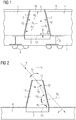
- Figure 1 shows a cross section of an exemplary embodiment of an optical package according to the present principle.
- the optical package comprises a carrier 4, an optoelectronic component 2, an aspheric lens 1, and a reflective layer 3.
- the carrier 4 comprises electrical interconnections 5. In this particular embodiment these are implemented as through substrate vias or wiring and electrically connect the optoelectric component 2 with an underside of the carrier 4. Bump contacts 6 are arranged at the underside of the carrier 4 for external electric connection of the optical package.
- the carrier 4 may be a semiconductor substrate, for example a wafer, so that the optical package can be produced in a CMOS process at the wafer level minimizing footprint and assembly costs.
- the carrier 4 may instead be any other carrier suitable for optoelectronic packages, like a printed circuit board, for instance.
- the optoelectric component 2 is mounted on or into the carrier 4 using semiconductor technology, for example. Generally, the optoelectric component 2 is arranged for detecting electromagnetic radiation within a certain specified wavelength range.
- the optical package can be used with a wide range of optoelectric components such as optical sensors. Examples include ambient light sensors, color sensors, active optical proximity sensors, especially photodiodes. Typically, further optical components like an interference filter may optionally be arranged at or on the optoelectronic component 2 (not shown).
- the aspheric lens 1 is arranged at or on the optoelectronic component 2 and comprises a transparent lens material such as an optical mold.
- the aspheric lens 1 is limited by boundary surfaces, i.e. an upper surface 11, a lateral surface 12, and a bottom surface 13.
- the bottom surface 13 faces the optoelectronic component 2 and is contiguous with a surface of the optoelectronic component 2.
- the upper surface 11 faces away from the optoelectronic component 2 and into an aperture 10 arranged in the encasement 7.
- the upper surface 11, in this particular embodiment, is flush with an outer surface of the encasement 7.
- the upper surface 11 comprises an essentially flat surface.
- An aperture 10 can be formed by the encasement 7, or by means of an optional cap layer 8 with a window provided to form the aperture 3 as shown in the drawing.
- the cap layer 8 may be opaque or semi-transparent to shield stray light, and its transparency may especially depend on the wavelength.
- the cap layer 8 may be formed by a metal shield, for instance.
- the lateral surface 12 surrounds the aspheric lens 1.
- the aspheric lens 1 constitutes a conical frustum and the lateral surface 12 is tapered towards the bottom surface 13.
- a surface profile of the aspheric lens 1 can be described by an analytical formula such as an aspheric surface profile.
- the aspheric lens 1 is rotationally symmetric about an optical axis which can be defined by a direction pointing from the bottom surface 13 towards the upper surface 11. This will be designated as a vertical direction d v .
- a direction orthogonal to the vertical direction d v is specified as a relevant lateral direction.
- Widths w 1 , w 2 of the aspheric lens 1 are defined parallel to said lateral direction and are limited by the lateral surface 12.
- Figure 1 shows a first width w 1 at a first distance d 1 from the bottom surface 13 and a smaller second width w 2 at a larger second distance d 2 from the bottom surface 13.
- the widths w 1 , w 2 decrease along the optical axis in the vertical direction d v from a maximal width at the bottom surface 13 to a non-vanishing minimal width at the upper surface 11.
- the reflective layer 3 comprises a reflective material.
- Reflectivity typically is a function of wavelength.
- the reflective material is at least partly reflective in the specified wavelength range of the optoelectric component 2.
- Such materials include metals and metal alloys.
- Aluminum (Al) yields a reflectivity of around 88 % to 92 % over the visible spectrum.
- Silver (Ag) has a reflectivity of 95% to 99% which extends even into the far infrared, but suffers from decreasing reflectivity ( ⁇ 90%) in the blue and ultraviolet spectral regions.
- Gold gives excellent (98% to 99%) reflectivity throughout the infrared, but has limited reflectivity at wavelengths shorter than 550 nm, resulting in the typical gold color.
- More complex reflective layers can be used to increase the reflectance.
- Such a metal would consist of several dielectric layers with alternating high and low indices of refraction, for example.
- HR high-reflection
- the reflective layer 3 in this embodiment covers the lateral surface 13 of the aspheric lens 1 completely. With the reflective layer 3 on lateral surface 13 of the aspheric lens 1 only the upper surface 12 is exposed for light entrance.
- the reflective layer 3 provides a reflective surface and robust light blocking (including NIR) from light impinging on the sides of the lens 1.
- the encasement 7 comprises a filler material and is arranged on the carrier 4.
- the encasement 7 can be formed by molding the filler material onto the carrier 4.
- the encasement comprises sidewalls which are in direct contact with or encapsulating the reflective layer 3.
- the reflective layer 3 can be coated onto the sidewalls or other surfaces of the encasement 7.
- the reflective layer 3 can be coated onto the lateral surface 12 of aspheric lens such that the encasement 7 can be placed on the reflective layer 3.
- the filler material is opaque within the specified wavelength range. Colours are possible as well to meet certain design constraints of a mobile device, for example.
- the filler material can be chosen to have a higher index of refraction compared to the lens material. This way no total internal reflection occurs at the boundary of lateral surface to sidewalls of the encasement.
- Figure 2 shows a cross section of another exemplary embodiment of an optical package according to the present principle.
- the reflective layer 3 covers both the lateral surface 12 of the aspheric lens 1 and a main surface of the carrier 4 completely. In this particular no encasement 7 is present or has not yet been placed onto the carrier 4.
- Figure 2 shows a ray 9 of incident light impinging on the upper surface 11 of the aspheric lens 1 at an angle a1 of incidence with respect to the normal n1 to the upper surface 11.
- the angle a2 of refraction differs from the angle a1 of incidence according to Snell's law, taking account of the index of refraction of the aspheric lens 1.
- the direction of the ray 9 thus deviates within the lens 1 from the direction of a virtual straight ray 9'.
- the refracted ray 9 reaches the lateral surface 12 of the aspheric lens 1 at a further angle a3 of incidence with respect to the normal n2 to the lateral surface 12.
- the ray 9 is reflected by the reflective layer 3.
- the angle a3' of reflection is the same as the further angle a3 of incidence, and the ray 9 is thus ultimately directed onto the optoelectronic component 2.
- the original inclination of the ray 9 with respect to the normal n1 is thus decreased, and the field of view of the optoelectronic component 2 is enlarged.
- a method for producing the optical package can be summarized as outlined below:
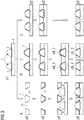
- Figure 3 shows an overview of different embodiments of a method for producing the optical package according to the present principle.
- a first step s1 an array of aspheric lenses 1 is created on a wafer surface as mentioned in the summary above.
- the array of aspheric lenses 1 is created directly on the wafer surface as carrier 4 using a wafer level transfer molding process.
- the aspheric lenses 3 are pre-fabricated and attached to the wafer or wafer parts (including single dies).
- the method can proceed in at least three different ways A, B, and C.
- A a separate encasement 7 is produced from the filler material.
- the encasement 7 comprises cavities 14 which are adjusted to fit the aspheric lenses 1.
- an inside surface 15 of those cavities 14 is metallized with the reflective layer 3. This could be done, e.g. using a common vacuum evaporation process or sputtering process.
- Typical reflective material may include a metal comprising aluminium, although other choices (such as chrome) are possible.
- the so metallized encasement 7 is placed onto the wafer in step s4 and attached to the wafer in step s5.
- a gap or void can be provided in between the encasement 7 and the aspheric lenses 1, for example to provide mechanical flexibility and reduce mechanical stress.
- step s2 involves application of the reflective layer 3 at least onto the lateral surfaces 12 of the aspheric lenses 1. This could be done, e.g. using a common vacuum evaporation process or sputtering process. Furthermore, the reflective layer 3 can also be applied to a large part or the entire wafer surface.
- step s3 then the filler material is added between the aspheric lenses 1 in order to form the encasement 7.
- the reflective layer 3 already blocks light (including NIR) from coming into the lateral surfaces 12 of the aspheric lenses 1, thus it can improve or entirely replace the light blocking action that is normally done using black mold compound. Addition of the filler material is still preferred for various reasons (package robustness, handling, etc.). Black material will give the most thorough side-light blocking, but other colours including white are also feasible.
- step s4 the aspheric lenses are freed from reflective material.
- the reflective material from the upper surface 11 needs to be removed.
- the exposure of the upper surfaces 11 is executed once the filler is hardened.
- this could be done by a CMP (chemical-mechanical polish) or by mild mechanical grinding following by polishing. It can also be possible to cut a thin layer from the upper surface, for example via an approach similar to tape planarization.
- the resulting upper surfaces 11 are essentially flat and flush with an outer surface of the encasement 7 (see step s5_1).
- Another approach is to selectively etch the reflective material from the upper surface 11 (see step s4_2).
- the filler material may protect the surfaces other than the lens upper surface from etching. If this is not the case, for example, a dedicated protective layer could be applied to the other surfaces, or only the upper surfaces 11 are brought into contact with the etching substances. The resulting upper surfaces 11 are free of reflective material and may protrude out of the encasement 7 (see step s5_2).
- the third approach C is similar to the second approach B.
- the upper surfaces 11 are excluded from coating, for example by covering the top by a shadow mask in step s2. This way step s4 can be omitted.
- Another approach (not shown) is to add a sacrificial layer to the upper surfaces 11 that is removed after application of the reflective material, e.g. after metallization, by means of a lift off process, for example.
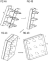
- FIG. 4 shows an embodiment of a method for producing the optical package according to the present principle. Depicted is a typical processing sequence for wafer-level packaging with through substrate vias (TSV). Not shown here is that the final product could also have a weak diffuser bonded to a top of the package. Alternately the top of the wafer could even be treated to create weakly diffusive surfaces at the upper surfaces 11 of the aspheric lenses 1.
- TSV through substrate vias
- An array of aspheric lenses 1 is formed by a clear and transparent mold compound and distributed on a wafer surface. Each aspheric lens 1 is placed on a corresponding optical electric component 2 (see Figure 4A ).
- the reflective layer 3 including the reflective material is deposited on the wafer surface, the lateral surfaces 12 and the upper surfaces 11 of the aspheric lenses 1.
- the drawing 4B depicts the resulting optical package after reflective metal deposition.
- the encasement 7 is formed by application of black filler material. Typically, in this step the encasement 7 completely encapsulates the aspheric lenses 1. Small apertures 10 are provided in the encasement 7 after CMP grinding and polishing (see Figure 4C ). The apertures 10 expose the upper surfaces 11 of the aspheric lenses 1 for light entrance. The wafer prepared in this way can then be singulated or diced into separate final optical packages (see Figure 4D ).
- the conical lenses in this embodiment could assume other shapes such as lenses with weakly hyperbolic or parabolic curves lateral surfaces 12.
- the general result is that in combination with the reflective layer also inverted tapered shapes will give a wide field of view to the outside world, while presenting a much narrower angular field of view to interference filters that may cover the optoelectric components 2. This is desirable because interference filters generally develop erroneous shifts in their spectral filtering characteristics for incident light that impinges at larger off-axis angles of incidence.
- runners used in the molding of the lenses, for example, and how these runners provide some leakage for light entering from the side of the package.
- the runners are necessary during the process where the liquid clear compound is initially injected into the mold. Generally the runners are minimized in cross-section so as to minimize the optical leakage.
Landscapes
- Physics & Mathematics (AREA)
- General Physics & Mathematics (AREA)
- Optics & Photonics (AREA)
- Light Receiving Elements (AREA)
- Led Device Packages (AREA)
- Engineering & Computer Science (AREA)
- Microelectronics & Electronic Packaging (AREA)
- Lenses (AREA)
Claims (15)
- Optisches Gehäuse, umfassend:- einen Träger (4), elektrische Verschaltungen (5) umfassend,- eine zum Erfassen elektromagnetischer Strahlung in einem spezifizierten Wellenlängenbereich eingerichtete optoelektronische Komponente (2), die am Träger (4) angebracht oder in diesen integriert ist, und die elektrisch an die elektrischen Verschaltungen (5) angeschlossen ist,- eine asphärische Linse (1) mit einer Oberseite (11), einer Seitenfläche (12) und einer Unterseite (13), wobei die Unterseite (13) an eine Fläche der optoelektronischen Komponente (2) angrenzt, und wobei die asphärische Linse (1) ein Material umfasst, das zumindest in dem spezifizierten Wellenlängenbereich transparent ist, und wobei die Oberseite (11) kleiner ist als die Unterseite (13),- eine reflektierende Schicht (3), ein reflektierendes Material umfassend, wobei die reflektierende Schicht (3) zumindest teilweise die Seitenfläche (12) der asphärischen Linse (1) bedeckt, und wobei das reflektierende Material in dem spezifizierten Wellenlängenbereich zumindest teilweise reflektierend ist,- eine Umhüllung (7), die auf dem Träger (4) angeordnet ist, wobei die Umhüllung (7) ein Füllmaterial und Seitenwände umfasst, welche die Seitenfläche (12) der asphärischen Linse (1) so einschließen, dass die Seitenwände in direktem Kontakt mit der reflektierenden Schicht (3) sind oder diese einkapseln.
- Optisches Gehäuse nach Anspruch 1, wobei- die reflektierende Schicht (3) die Seitenfläche (12) vollständig bedeckt, und/oder- die reflektierende Schicht (3) zumindest Teile einer Hauptfläche des Trägers (4) bedeckt, insbesondere die Hauptfläche des Trägers (4) vollständig bedeckt.
- Optisches Gehäuse nach Anspruch 1 oder 2, wobei das Füllmaterial im Vergleich zu einem Linsenmaterial der asphärischen Linse (1) einen höheren Brechungsindex hat.
- Optisches Gehäuse nach Anspruch 3, wobei- die reflektierende Schicht (3) als Schicht auf die Seitenfläche (12) der asphärischen Linse (1) aufgebracht ist, oder- die reflektierende Schicht (3) als Schicht auf die Seitenwände der Umhüllung (7) aufgebracht ist.
- Optisches Gehäuse nach einem der Ansprüche 1 bis 4, wobei das reflektierende Material der reflektierenden Schicht (3) mindestens eine Art von Metall und/oder eine Metalllegierung, insbesondere Aluminium, Chrom, Gold, Silber und/oder eine Legierung von diesen umfasst.
- Optisches Gehäuse nach einem der Ansprüche 1 bis 5, wobei das Füllmaterial zumindest im spezifizierten Wellenlängenbereich opak ist, das Füllmaterial insbesondere ein formbares Material umfasst.
- Optisches Gehäuse nach einem der Ansprüche 1 bis 6, wobei die optoelektronische Komponente (2) umfasst:- einen optischen Sensor,- einen Umgebungslichtsensor,- einen Farbsensor,- einen optischen Näherungssensor;- eine Photodiode.
- Optisches Gehäuse nach einem der Ansprüche 1 bis 7, wobei- die asphärische Linse (1) eine optische Achse hat, und- die Seitenfläche (12) zumindest abschnittsweise ein asphärisches Oberflächenprofil in Bezug auf die optische Achse hat.
- Optisches Gehäuse nach Anspruch 8, wobei das asphärische Oberflächenprofil zumindest abschnittsweise- hyperbolisch,- parabolisch,- elliptisch, und/oder- linear,- konisch, und/oder- sich verjüngend- oder ein Pyramidenstumpf davon ist.
- Optisches Gehäuse nach einem der Ansprüche 8 oder 9, wobei eine Länge der asphärischen Linse (1) entlang ihrer optischen Achse zumindest gleich einer oder größer als eine Breite der Unterseite (13) ist.
- Optisches Gehäuse nach Anspruch 10, wobei die Breite der Unterseite (13) zumindest gleich einer oder größer als eine Breite eines lichtempfindlichen Bereichs der optoelektronischen Komponente (2) ist.
- Optisches Gehäuse nach einem der Ansprüche 3 bis 11, wobei die Umhüllung (7) eine Öffnung (10) an oder nahe der Oberseite (11) umfasst, die zum Lichteintritt in die asphärische Linse (1) angeordnet ist.
- Optisches Gehäuse nach einem der Ansprüche 1 bis 12, wobei ein Diffusor an oder nahe der Oberseite (13) der asphärischen Linse (1) angeordnet ist.
- Verfahren zum Herstellen eines optischen Gehäuses, die folgenden Schritte umfassend:- Bereitstellen eines Wafers als Träger (4) mit elektrischen Verschaltungen (5),- Montieren mehrerer optoelektronischer Komponenten (2) am oder in den Wafer, wobei die optoelektronischen Komponenten (2) zum Erfassen elektromagnetischer Strahlung in einem spezifizierten Wellenlängenbereich eingerichtet sind,- elektrisches Anschließen der optoelektronischen Komponenten (2) an die elektrischen Verschaltungen (5),- Ausbilden mindestens einer asphärischen Linse (1) mit einer Oberseite (11), einer Seitenfläche (12) und einer Unterseit (13), aus einem Material, das zumindest in dem spezifizierten Wellenlängenbereich transparent ist, und wobei die Oberseite (11) kleiner ist als die Unterseite (13),- Anordnen der asphärischen Linse (1) mit ihrer Unterseite (13) jeweils an eine Oberfläche der optoelektronischen Komponenten (2) angrenzend,- Bedecken der Oberseite (11), der Seitenfläche (12) und der Unterseite (13) mit einer reflektierenden Schicht (3), die ein reflektierendes Material umfasst, wobei das reflektierende Material im spezifizierten Wellenlängenbereich zumindest teilweise reflektierend ist,- Ausbilden einer Umhüllung (7) auf dem Wafer als Träger (4), die ein Füllmaterial und Seitenwände umfasst, welche die Seitenfläche (12) der asphärischen Linse (1) zumndest teilweise so einschließen, dass die Seitenwände in direktem Kontakt mit der reflektierenden Schicht (3) sind oder diese einkapseln, und- Vereinzeln des die mehreren optoelektronischen Komponenten (2) tragenden Wafers zu einzelnen optischen Gehäusen.
- Verfahren nach Anspruch 14, wobei- mehrere Öffnungen (10) jeweils in der Umhüllung (7) an oder nahe den Oberseiten (11) der asphärischen Linsen (1) ausgebildet werden,- die Oberseiten (12) der asphärischen Linsen (1) in die Öffnungen (10) vorstehen, oder die Oberseiten (11) modifiziert werden, um mit einer Außenseite der Umhüllung (7) bündig abzuschließen.
Priority Applications (3)
| Application Number | Priority Date | Filing Date | Title |
|---|---|---|---|
| US15/773,539 US10847664B2 (en) | 2015-11-06 | 2016-11-04 | Optical package and method of producing an optical package |
| CN201680064714.6A CN108271423A (zh) | 2015-11-06 | 2016-11-04 | 光学封装和生产光学封装的方法 |
| PCT/EP2016/076695 WO2017077051A1 (en) | 2015-11-06 | 2016-11-04 | Optical package and method of producing an optical package |
Applications Claiming Priority (1)
| Application Number | Priority Date | Filing Date | Title |
|---|---|---|---|
| US201562252320P | 2015-11-06 | 2015-11-06 |
Publications (2)
| Publication Number | Publication Date |
|---|---|
| EP3166146A1 EP3166146A1 (de) | 2017-05-10 |
| EP3166146B1 true EP3166146B1 (de) | 2019-04-17 |
Family
ID=54843714
Family Applications (1)
| Application Number | Title | Priority Date | Filing Date |
|---|---|---|---|
| EP15198468.9A Active EP3166146B1 (de) | 2015-11-06 | 2015-12-08 | Optische einheit und verfahren zur herstellung einer optischen einheit |
Country Status (4)
| Country | Link |
|---|---|
| US (1) | US10847664B2 (de) |
| EP (1) | EP3166146B1 (de) |
| CN (1) | CN108271423A (de) |
| WO (1) | WO2017077051A1 (de) |
Families Citing this family (7)
| Publication number | Priority date | Publication date | Assignee | Title |
|---|---|---|---|---|
| US10649156B2 (en) * | 2016-12-23 | 2020-05-12 | Avago Technologies International Sales Pte. Limited | Optical sensing device having integrated optics and methods of manufacturing the same |
| EP3435045B1 (de) * | 2017-07-27 | 2023-12-13 | ams AG | Optisches sensorpaket |
| FR3069955A1 (fr) * | 2017-08-04 | 2019-02-08 | Stmicroelectronics (Crolles 2) Sas | Dispositif electronique capteur d'images a couche additionnelle formant des lentilles optiques |
| KR102711649B1 (ko) * | 2019-09-23 | 2024-09-30 | 삼성전자 주식회사 | 디스플레이 및 카메라 장치를 포함하는 전자 장치 |
| US12011057B2 (en) | 2020-01-13 | 2024-06-18 | Msa Technology, Llc | Safety helmet |
| CN114833360B (zh) * | 2022-04-28 | 2023-09-26 | 同济大学 | 一种tir透镜的分段式超精密车削加工方法 |
| US20230369370A1 (en) * | 2022-05-13 | 2023-11-16 | Taiwan Semiconductor Manufacturing Company, Ltd. | Package structure and manufacturing method thereof |
Family Cites Families (11)
| Publication number | Priority date | Publication date | Assignee | Title |
|---|---|---|---|---|
| JPH1010394A (ja) * | 1996-04-26 | 1998-01-16 | Chiyuugai Oputoronikusu Kk | 電子撮像装置 |
| JP4004705B2 (ja) * | 2000-02-29 | 2007-11-07 | 松下電器産業株式会社 | 撮像装置と撮像装置組立方法 |
| JP2005064198A (ja) * | 2003-08-11 | 2005-03-10 | Seiko Epson Corp | 半導体装置及びその製造方法 |
| US7221524B2 (en) * | 2004-01-30 | 2007-05-22 | Fujifilm Corporation | Lens unit and compact image pickup module |
| GB0412436D0 (en) * | 2004-06-04 | 2004-07-07 | Melexis Nv | Semiconductor package with transparent lid |
| US7329982B2 (en) * | 2004-10-29 | 2008-02-12 | 3M Innovative Properties Company | LED package with non-bonded optical element |
| KR100665216B1 (ko) * | 2005-07-04 | 2007-01-09 | 삼성전기주식회사 | 개선된 측벽 반사 구조를 갖는 측면형 발광다이오드 |
| KR101651157B1 (ko) * | 2009-08-13 | 2016-08-25 | 후지필름 가부시키가이샤 | 웨이퍼 레벨 렌즈, 웨이퍼 레벨 렌즈의 제조 방법, 및 촬상 유닛 |
| JP5701532B2 (ja) * | 2010-07-23 | 2015-04-15 | オリンパス株式会社 | 撮像装置の製造方法 |
| US8987658B2 (en) * | 2012-11-28 | 2015-03-24 | Intersil Americas LLC | Packaged light detector semiconductor devices with non-imaging optical concentrators for ambient light and/or optical proxmity sensing, methods for manufacturing the same, and systems including the same |
| EP2966491B1 (de) * | 2014-07-09 | 2022-02-02 | ams AG | Linsenanordnung, optoelektronisches Gehäuse und Verfahren zur Herstellung eines optoelektronischen Wafer-Gehäuses mit der Linsenanordnung |
-
2015
- 2015-12-08 EP EP15198468.9A patent/EP3166146B1/de active Active
-
2016
- 2016-11-04 US US15/773,539 patent/US10847664B2/en active Active
- 2016-11-04 CN CN201680064714.6A patent/CN108271423A/zh active Pending
- 2016-11-04 WO PCT/EP2016/076695 patent/WO2017077051A1/en not_active Ceased
Non-Patent Citations (1)
| Title |
|---|
| None * |
Also Published As
| Publication number | Publication date |
|---|---|
| CN108271423A (zh) | 2018-07-10 |
| US10847664B2 (en) | 2020-11-24 |
| US20180323320A1 (en) | 2018-11-08 |
| EP3166146A1 (de) | 2017-05-10 |
| WO2017077051A1 (en) | 2017-05-11 |
Similar Documents
| Publication | Publication Date | Title |
|---|---|---|
| EP3166146B1 (de) | Optische einheit und verfahren zur herstellung einer optischen einheit | |
| EP2084896B1 (de) | Steuerung von streulicht in kamerasystemen mit einem optikstapel und entsprechende verfahren | |
| CN210349840U (zh) | 光学传感器 | |
| JP5198394B2 (ja) | 近接照度センサおよびその製造方法 | |
| US8876304B2 (en) | Imaging assembly | |
| EP3971763B1 (de) | Fingerabdruckerkennungseinrichtung und elektronische vorrichtung | |
| TWI596787B (zh) | 用於環境光及/或光學近場感測的具有非成像光學元件的經封裝光偵測器半導體裝置,製造其的方法及包含其的系統 | |
| KR20180005588A (ko) | 디스플레이 패널의 광원들을 이용한 지문 센서, 지문 센서 패키지 및 지문 센싱 시스템 | |
| KR100705349B1 (ko) | 고체촬상장치, 반도체 웨이퍼 및 카메라 모듈 | |
| EP3261122B1 (de) | 3d-integrierter optischer sensor und verfahren zur herstellung eines 3d-integrierten optischen sensors | |
| WO2021077265A1 (zh) | 指纹识别装置和电子设备 | |
| TWI903080B (zh) | 濾光裝置及光檢測裝置 | |
| US10319767B2 (en) | Electronic component including an optical member fixed with adhesive | |
| US20070152227A1 (en) | Cmos image sensor | |
| CN211480030U (zh) | 薄型化光学指纹识别装置 | |
| CN213184287U (zh) | 光学指纹器件 | |
| CN100502022C (zh) | 半导体装置 | |
| CN113314619A (zh) | 多光谱光学传感器封装结构及其封装方法 | |
| EP3282480B1 (de) | Verfahren zur herstellung eines optischen sensors auf waferebene und optischer sensor | |
| TW202123482A (zh) | 晶片封裝體及其製造方法 | |
| TWM637704U (zh) | 光學感測模組 | |
| JP2008028220A (ja) | 照度センサ | |
| CN118250545A (zh) | 一种摄像模组 | |
| KR100925649B1 (ko) | 적외선 차단 필터 일체형 렌즈 모듈 | |
| KR20020002536A (ko) | 이미지센서의 칩 스케일 패키지 |
Legal Events
| Date | Code | Title | Description |
|---|---|---|---|
| PUAI | Public reference made under article 153(3) epc to a published international application that has entered the european phase |
Free format text: ORIGINAL CODE: 0009012 |
|
| STAA | Information on the status of an ep patent application or granted ep patent |
Free format text: STATUS: THE APPLICATION HAS BEEN PUBLISHED |
|
| AK | Designated contracting states |
Kind code of ref document: A1 Designated state(s): AL AT BE BG CH CY CZ DE DK EE ES FI FR GB GR HR HU IE IS IT LI LT LU LV MC MK MT NL NO PL PT RO RS SE SI SK SM TR |
|
| AX | Request for extension of the european patent |
Extension state: BA ME |
|
| STAA | Information on the status of an ep patent application or granted ep patent |
Free format text: STATUS: REQUEST FOR EXAMINATION WAS MADE |
|
| 17P | Request for examination filed |
Effective date: 20171110 |
|
| RBV | Designated contracting states (corrected) |
Designated state(s): AL AT BE BG CH CY CZ DE DK EE ES FI FR GB GR HR HU IE IS IT LI LT LU LV MC MK MT NL NO PL PT RO RS SE SI SK SM TR |
|
| GRAP | Despatch of communication of intention to grant a patent |
Free format text: ORIGINAL CODE: EPIDOSNIGR1 |
|
| STAA | Information on the status of an ep patent application or granted ep patent |
Free format text: STATUS: GRANT OF PATENT IS INTENDED |
|
| INTG | Intention to grant announced |
Effective date: 20181122 |
|
| RAP1 | Party data changed (applicant data changed or rights of an application transferred) |
Owner name: AMS AG |
|
| GRAS | Grant fee paid |
Free format text: ORIGINAL CODE: EPIDOSNIGR3 |
|
| GRAA | (expected) grant |
Free format text: ORIGINAL CODE: 0009210 |
|
| STAA | Information on the status of an ep patent application or granted ep patent |
Free format text: STATUS: THE PATENT HAS BEEN GRANTED |
|
| RIN1 | Information on inventor provided before grant (corrected) |
Inventor name: ETSCHMAIER, HARALD Inventor name: SCHRANK, FRANZ Inventor name: BODNER, THOMAS Inventor name: TOSCHKOFF, GREGOR Inventor name: MEHRL, DAVID |
|
| AK | Designated contracting states |
Kind code of ref document: B1 Designated state(s): AL AT BE BG CH CY CZ DE DK EE ES FI FR GB GR HR HU IE IS IT LI LT LU LV MC MK MT NL NO PL PT RO RS SE SI SK SM TR |
|
| REG | Reference to a national code |
Ref country code: GB Ref legal event code: FG4D |
|
| REG | Reference to a national code |
Ref country code: CH Ref legal event code: EP |
|
| REG | Reference to a national code |
Ref country code: DE Ref legal event code: R096 Ref document number: 602015028394 Country of ref document: DE |
|
| REG | Reference to a national code |
Ref country code: AT Ref legal event code: REF Ref document number: 1122505 Country of ref document: AT Kind code of ref document: T Effective date: 20190515 Ref country code: IE Ref legal event code: FG4D |
|
| REG | Reference to a national code |
Ref country code: NL Ref legal event code: MP Effective date: 20190417 |
|
| REG | Reference to a national code |
Ref country code: LT Ref legal event code: MG4D |
|
| PG25 | Lapsed in a contracting state [announced via postgrant information from national office to epo] |
Ref country code: NL Free format text: LAPSE BECAUSE OF FAILURE TO SUBMIT A TRANSLATION OF THE DESCRIPTION OR TO PAY THE FEE WITHIN THE PRESCRIBED TIME-LIMIT Effective date: 20190417 |
|
| PG25 | Lapsed in a contracting state [announced via postgrant information from national office to epo] |
Ref country code: LT Free format text: LAPSE BECAUSE OF FAILURE TO SUBMIT A TRANSLATION OF THE DESCRIPTION OR TO PAY THE FEE WITHIN THE PRESCRIBED TIME-LIMIT Effective date: 20190417 Ref country code: FI Free format text: LAPSE BECAUSE OF FAILURE TO SUBMIT A TRANSLATION OF THE DESCRIPTION OR TO PAY THE FEE WITHIN THE PRESCRIBED TIME-LIMIT Effective date: 20190417 Ref country code: AL Free format text: LAPSE BECAUSE OF FAILURE TO SUBMIT A TRANSLATION OF THE DESCRIPTION OR TO PAY THE FEE WITHIN THE PRESCRIBED TIME-LIMIT Effective date: 20190417 Ref country code: ES Free format text: LAPSE BECAUSE OF FAILURE TO SUBMIT A TRANSLATION OF THE DESCRIPTION OR TO PAY THE FEE WITHIN THE PRESCRIBED TIME-LIMIT Effective date: 20190417 Ref country code: SE Free format text: LAPSE BECAUSE OF FAILURE TO SUBMIT A TRANSLATION OF THE DESCRIPTION OR TO PAY THE FEE WITHIN THE PRESCRIBED TIME-LIMIT Effective date: 20190417 Ref country code: HR Free format text: LAPSE BECAUSE OF FAILURE TO SUBMIT A TRANSLATION OF THE DESCRIPTION OR TO PAY THE FEE WITHIN THE PRESCRIBED TIME-LIMIT Effective date: 20190417 Ref country code: PT Free format text: LAPSE BECAUSE OF FAILURE TO SUBMIT A TRANSLATION OF THE DESCRIPTION OR TO PAY THE FEE WITHIN THE PRESCRIBED TIME-LIMIT Effective date: 20190817 Ref country code: NO Free format text: LAPSE BECAUSE OF FAILURE TO SUBMIT A TRANSLATION OF THE DESCRIPTION OR TO PAY THE FEE WITHIN THE PRESCRIBED TIME-LIMIT Effective date: 20190717 |
|
| PG25 | Lapsed in a contracting state [announced via postgrant information from national office to epo] |
Ref country code: GR Free format text: LAPSE BECAUSE OF FAILURE TO SUBMIT A TRANSLATION OF THE DESCRIPTION OR TO PAY THE FEE WITHIN THE PRESCRIBED TIME-LIMIT Effective date: 20190718 Ref country code: PL Free format text: LAPSE BECAUSE OF FAILURE TO SUBMIT A TRANSLATION OF THE DESCRIPTION OR TO PAY THE FEE WITHIN THE PRESCRIBED TIME-LIMIT Effective date: 20190417 Ref country code: LV Free format text: LAPSE BECAUSE OF FAILURE TO SUBMIT A TRANSLATION OF THE DESCRIPTION OR TO PAY THE FEE WITHIN THE PRESCRIBED TIME-LIMIT Effective date: 20190417 Ref country code: RS Free format text: LAPSE BECAUSE OF FAILURE TO SUBMIT A TRANSLATION OF THE DESCRIPTION OR TO PAY THE FEE WITHIN THE PRESCRIBED TIME-LIMIT Effective date: 20190417 Ref country code: BG Free format text: LAPSE BECAUSE OF FAILURE TO SUBMIT A TRANSLATION OF THE DESCRIPTION OR TO PAY THE FEE WITHIN THE PRESCRIBED TIME-LIMIT Effective date: 20190717 |
|
| REG | Reference to a national code |
Ref country code: AT Ref legal event code: MK05 Ref document number: 1122505 Country of ref document: AT Kind code of ref document: T Effective date: 20190417 |
|
| PG25 | Lapsed in a contracting state [announced via postgrant information from national office to epo] |
Ref country code: IS Free format text: LAPSE BECAUSE OF FAILURE TO SUBMIT A TRANSLATION OF THE DESCRIPTION OR TO PAY THE FEE WITHIN THE PRESCRIBED TIME-LIMIT Effective date: 20190817 |
|
| REG | Reference to a national code |
Ref country code: DE Ref legal event code: R097 Ref document number: 602015028394 Country of ref document: DE |
|
| PG25 | Lapsed in a contracting state [announced via postgrant information from national office to epo] |
Ref country code: SK Free format text: LAPSE BECAUSE OF FAILURE TO SUBMIT A TRANSLATION OF THE DESCRIPTION OR TO PAY THE FEE WITHIN THE PRESCRIBED TIME-LIMIT Effective date: 20190417 Ref country code: EE Free format text: LAPSE BECAUSE OF FAILURE TO SUBMIT A TRANSLATION OF THE DESCRIPTION OR TO PAY THE FEE WITHIN THE PRESCRIBED TIME-LIMIT Effective date: 20190417 Ref country code: CZ Free format text: LAPSE BECAUSE OF FAILURE TO SUBMIT A TRANSLATION OF THE DESCRIPTION OR TO PAY THE FEE WITHIN THE PRESCRIBED TIME-LIMIT Effective date: 20190417 Ref country code: RO Free format text: LAPSE BECAUSE OF FAILURE TO SUBMIT A TRANSLATION OF THE DESCRIPTION OR TO PAY THE FEE WITHIN THE PRESCRIBED TIME-LIMIT Effective date: 20190417 Ref country code: AT Free format text: LAPSE BECAUSE OF FAILURE TO SUBMIT A TRANSLATION OF THE DESCRIPTION OR TO PAY THE FEE WITHIN THE PRESCRIBED TIME-LIMIT Effective date: 20190417 Ref country code: DK Free format text: LAPSE BECAUSE OF FAILURE TO SUBMIT A TRANSLATION OF THE DESCRIPTION OR TO PAY THE FEE WITHIN THE PRESCRIBED TIME-LIMIT Effective date: 20190417 |
|
| PLBE | No opposition filed within time limit |
Free format text: ORIGINAL CODE: 0009261 |
|
| STAA | Information on the status of an ep patent application or granted ep patent |
Free format text: STATUS: NO OPPOSITION FILED WITHIN TIME LIMIT |
|
| PG25 | Lapsed in a contracting state [announced via postgrant information from national office to epo] |
Ref country code: SM Free format text: LAPSE BECAUSE OF FAILURE TO SUBMIT A TRANSLATION OF THE DESCRIPTION OR TO PAY THE FEE WITHIN THE PRESCRIBED TIME-LIMIT Effective date: 20190417 Ref country code: IT Free format text: LAPSE BECAUSE OF FAILURE TO SUBMIT A TRANSLATION OF THE DESCRIPTION OR TO PAY THE FEE WITHIN THE PRESCRIBED TIME-LIMIT Effective date: 20190417 |
|
| 26N | No opposition filed |
Effective date: 20200120 |
|
| PG25 | Lapsed in a contracting state [announced via postgrant information from national office to epo] |
Ref country code: TR Free format text: LAPSE BECAUSE OF FAILURE TO SUBMIT A TRANSLATION OF THE DESCRIPTION OR TO PAY THE FEE WITHIN THE PRESCRIBED TIME-LIMIT Effective date: 20190417 |
|
| PG25 | Lapsed in a contracting state [announced via postgrant information from national office to epo] |
Ref country code: SI Free format text: LAPSE BECAUSE OF FAILURE TO SUBMIT A TRANSLATION OF THE DESCRIPTION OR TO PAY THE FEE WITHIN THE PRESCRIBED TIME-LIMIT Effective date: 20190417 |
|
| REG | Reference to a national code |
Ref country code: CH Ref legal event code: PL |
|
| REG | Reference to a national code |
Ref country code: BE Ref legal event code: MM Effective date: 20191231 |
|
| PG25 | Lapsed in a contracting state [announced via postgrant information from national office to epo] |
Ref country code: MC Free format text: LAPSE BECAUSE OF FAILURE TO SUBMIT A TRANSLATION OF THE DESCRIPTION OR TO PAY THE FEE WITHIN THE PRESCRIBED TIME-LIMIT Effective date: 20190417 |
|
| PG25 | Lapsed in a contracting state [announced via postgrant information from national office to epo] |
Ref country code: IE Free format text: LAPSE BECAUSE OF NON-PAYMENT OF DUE FEES Effective date: 20191208 Ref country code: LU Free format text: LAPSE BECAUSE OF NON-PAYMENT OF DUE FEES Effective date: 20191208 |
|
| PG25 | Lapsed in a contracting state [announced via postgrant information from national office to epo] |
Ref country code: BE Free format text: LAPSE BECAUSE OF NON-PAYMENT OF DUE FEES Effective date: 20191231 Ref country code: CH Free format text: LAPSE BECAUSE OF NON-PAYMENT OF DUE FEES Effective date: 20191231 Ref country code: LI Free format text: LAPSE BECAUSE OF NON-PAYMENT OF DUE FEES Effective date: 20191231 |
|
| PG25 | Lapsed in a contracting state [announced via postgrant information from national office to epo] |
Ref country code: CY Free format text: LAPSE BECAUSE OF FAILURE TO SUBMIT A TRANSLATION OF THE DESCRIPTION OR TO PAY THE FEE WITHIN THE PRESCRIBED TIME-LIMIT Effective date: 20190417 |
|
| PG25 | Lapsed in a contracting state [announced via postgrant information from national office to epo] |
Ref country code: HU Free format text: LAPSE BECAUSE OF FAILURE TO SUBMIT A TRANSLATION OF THE DESCRIPTION OR TO PAY THE FEE WITHIN THE PRESCRIBED TIME-LIMIT; INVALID AB INITIO Effective date: 20151208 Ref country code: MT Free format text: LAPSE BECAUSE OF FAILURE TO SUBMIT A TRANSLATION OF THE DESCRIPTION OR TO PAY THE FEE WITHIN THE PRESCRIBED TIME-LIMIT Effective date: 20190417 |
|
| PG25 | Lapsed in a contracting state [announced via postgrant information from national office to epo] |
Ref country code: MK Free format text: LAPSE BECAUSE OF FAILURE TO SUBMIT A TRANSLATION OF THE DESCRIPTION OR TO PAY THE FEE WITHIN THE PRESCRIBED TIME-LIMIT Effective date: 20190417 |
|
| P01 | Opt-out of the competence of the unified patent court (upc) registered |
Effective date: 20230822 |
|
| REG | Reference to a national code |
Ref country code: DE Ref legal event code: R079 Ref document number: 602015028394 Country of ref document: DE Free format text: PREVIOUS MAIN CLASS: H01L0025160000 Ipc: H10W0090000000 |
|
| PGFP | Annual fee paid to national office [announced via postgrant information from national office to epo] |
Ref country code: DE Payment date: 20251211 Year of fee payment: 11 |
|
| PGFP | Annual fee paid to national office [announced via postgrant information from national office to epo] |
Ref country code: GB Payment date: 20251219 Year of fee payment: 11 |
|
| PGFP | Annual fee paid to national office [announced via postgrant information from national office to epo] |
Ref country code: FR Payment date: 20251223 Year of fee payment: 11 |