EP2084896B1 - Steuerung von streulicht in kamerasystemen mit einem optikstapel und entsprechende verfahren - Google Patents
Steuerung von streulicht in kamerasystemen mit einem optikstapel und entsprechende verfahren Download PDFInfo
- Publication number
- EP2084896B1 EP2084896B1 EP07840058.7A EP07840058A EP2084896B1 EP 2084896 B1 EP2084896 B1 EP 2084896B1 EP 07840058 A EP07840058 A EP 07840058A EP 2084896 B1 EP2084896 B1 EP 2084896B1
- Authority
- EP
- European Patent Office
- Prior art keywords
- camera system
- optics stack
- substrate
- encapsulant
- substrates
- Prior art date
- Legal status (The legal status is an assumption and is not a legal conclusion. Google has not performed a legal analysis and makes no representation as to the accuracy of the status listed.)
- Not-in-force
Links
- 238000000034 method Methods 0.000 title description 7
- 239000000758 substrate Substances 0.000 claims description 120
- 239000008393 encapsulating agent Substances 0.000 claims description 51
- 230000003287 optical effect Effects 0.000 claims description 14
- 230000000452 restraining effect Effects 0.000 claims description 5
- 239000000463 material Substances 0.000 description 34
- 125000006850 spacer group Chemical group 0.000 description 10
- 235000012431 wafers Nutrition 0.000 description 8
- 239000011248 coating agent Substances 0.000 description 6
- 238000000576 coating method Methods 0.000 description 6
- 210000001747 pupil Anatomy 0.000 description 6
- 230000000903 blocking effect Effects 0.000 description 5
- 238000003384 imaging method Methods 0.000 description 3
- 238000012634 optical imaging Methods 0.000 description 3
- 239000011347 resin Substances 0.000 description 2
- 229920005989 resin Polymers 0.000 description 2
- OKTJSMMVPCPJKN-UHFFFAOYSA-N Carbon Chemical compound [C] OKTJSMMVPCPJKN-UHFFFAOYSA-N 0.000 description 1
- VYPSYNLAJGMNEJ-UHFFFAOYSA-N Silicium dioxide Chemical compound O=[Si]=O VYPSYNLAJGMNEJ-UHFFFAOYSA-N 0.000 description 1
- 239000000853 adhesive Substances 0.000 description 1
- 230000001070 adhesive effect Effects 0.000 description 1
- 230000004075 alteration Effects 0.000 description 1
- 229910052799 carbon Inorganic materials 0.000 description 1
- 239000003086 colorant Substances 0.000 description 1
- 239000000356 contaminant Substances 0.000 description 1
- 230000008021 deposition Effects 0.000 description 1
- 230000008030 elimination Effects 0.000 description 1
- 238000003379 elimination reaction Methods 0.000 description 1
- 230000007613 environmental effect Effects 0.000 description 1
- 230000008020 evaporation Effects 0.000 description 1
- 238000001704 evaporation Methods 0.000 description 1
- 239000005350 fused silica glass Substances 0.000 description 1
- 239000011521 glass Substances 0.000 description 1
- 238000011463 hyperthermic intraperitoneal chemotherapy Methods 0.000 description 1
- 238000007654 immersion Methods 0.000 description 1
- 238000001746 injection moulding Methods 0.000 description 1
- 239000007788 liquid Substances 0.000 description 1
- 239000002184 metal Substances 0.000 description 1
- 238000010422 painting Methods 0.000 description 1
- 238000000059 patterning Methods 0.000 description 1
- 229920001296 polysiloxane Polymers 0.000 description 1
- 239000011253 protective coating Substances 0.000 description 1
- 239000000565 sealant Substances 0.000 description 1
- 238000007789 sealing Methods 0.000 description 1
- 239000004065 semiconductor Substances 0.000 description 1
- 238000000926 separation method Methods 0.000 description 1
Images


Classifications
-
- G—PHYSICS
- G03—PHOTOGRAPHY; CINEMATOGRAPHY; ANALOGOUS TECHNIQUES USING WAVES OTHER THAN OPTICAL WAVES; ELECTROGRAPHY; HOLOGRAPHY
- G03B—APPARATUS OR ARRANGEMENTS FOR TAKING PHOTOGRAPHS OR FOR PROJECTING OR VIEWING THEM; APPARATUS OR ARRANGEMENTS EMPLOYING ANALOGOUS TECHNIQUES USING WAVES OTHER THAN OPTICAL WAVES; ACCESSORIES THEREFOR
- G03B17/00—Details of cameras or camera bodies; Accessories therefor
- G03B17/02—Bodies
- G03B17/12—Bodies with means for supporting objectives, supplementary lenses, filters, masks, or turrets
-
- G—PHYSICS
- G02—OPTICS
- G02B—OPTICAL ELEMENTS, SYSTEMS OR APPARATUS
- G02B27/00—Optical systems or apparatus not provided for by any of the groups G02B1/00 - G02B26/00, G02B30/00
- G02B27/0018—Optical systems or apparatus not provided for by any of the groups G02B1/00 - G02B26/00, G02B30/00 with means for preventing ghost images
-
- G—PHYSICS
- G02—OPTICS
- G02B—OPTICAL ELEMENTS, SYSTEMS OR APPARATUS
- G02B7/00—Mountings, adjusting means, or light-tight connections, for optical elements
- G02B7/02—Mountings, adjusting means, or light-tight connections, for optical elements for lenses
- G02B7/021—Mountings, adjusting means, or light-tight connections, for optical elements for lenses for more than one lens
-
- H—ELECTRICITY
- H01—ELECTRIC ELEMENTS
- H01L—SEMICONDUCTOR DEVICES NOT COVERED BY CLASS H10
- H01L27/00—Devices consisting of a plurality of semiconductor or other solid-state components formed in or on a common substrate
- H01L27/14—Devices consisting of a plurality of semiconductor or other solid-state components formed in or on a common substrate including semiconductor components sensitive to infrared radiation, light, electromagnetic radiation of shorter wavelength or corpuscular radiation and specially adapted either for the conversion of the energy of such radiation into electrical energy or for the control of electrical energy by such radiation
- H01L27/144—Devices controlled by radiation
- H01L27/146—Imager structures
- H01L27/14601—Structural or functional details thereof
- H01L27/14618—Containers
-
- H—ELECTRICITY
- H04—ELECTRIC COMMUNICATION TECHNIQUE
- H04N—PICTORIAL COMMUNICATION, e.g. TELEVISION
- H04N23/00—Cameras or camera modules comprising electronic image sensors; Control thereof
- H04N23/50—Constructional details
- H04N23/55—Optical parts specially adapted for electronic image sensors; Mounting thereof
-
- H—ELECTRICITY
- H04—ELECTRIC COMMUNICATION TECHNIQUE
- H04N—PICTORIAL COMMUNICATION, e.g. TELEVISION
- H04N23/00—Cameras or camera modules comprising electronic image sensors; Control thereof
- H04N23/57—Mechanical or electrical details of cameras or camera modules specially adapted for being embedded in other devices
-
- H—ELECTRICITY
- H05—ELECTRIC TECHNIQUES NOT OTHERWISE PROVIDED FOR
- H05K—PRINTED CIRCUITS; CASINGS OR CONSTRUCTIONAL DETAILS OF ELECTRIC APPARATUS; MANUFACTURE OF ASSEMBLAGES OF ELECTRICAL COMPONENTS
- H05K1/00—Printed circuits
- H05K1/02—Details
- H05K1/11—Printed elements for providing electric connections to or between printed circuits
- H05K1/111—Pads for surface mounting, e.g. lay-out
-
- H—ELECTRICITY
- H05—ELECTRIC TECHNIQUES NOT OTHERWISE PROVIDED FOR
- H05K—PRINTED CIRCUITS; CASINGS OR CONSTRUCTIONAL DETAILS OF ELECTRIC APPARATUS; MANUFACTURE OF ASSEMBLAGES OF ELECTRICAL COMPONENTS
- H05K1/00—Printed circuits
- H05K1/02—Details
- H05K1/14—Structural association of two or more printed circuits
-
- H—ELECTRICITY
- H01—ELECTRIC ELEMENTS
- H01L—SEMICONDUCTOR DEVICES NOT COVERED BY CLASS H10
- H01L2224/00—Indexing scheme for arrangements for connecting or disconnecting semiconductor or solid-state bodies and methods related thereto as covered by H01L24/00
- H01L2224/01—Means for bonding being attached to, or being formed on, the surface to be connected, e.g. chip-to-package, die-attach, "first-level" interconnects; Manufacturing methods related thereto
- H01L2224/42—Wire connectors; Manufacturing methods related thereto
- H01L2224/47—Structure, shape, material or disposition of the wire connectors after the connecting process
- H01L2224/48—Structure, shape, material or disposition of the wire connectors after the connecting process of an individual wire connector
- H01L2224/4805—Shape
- H01L2224/4809—Loop shape
- H01L2224/48091—Arched
Definitions
- the present invention is directed to a camera system and associated methods. More particularly, the present invention is directed to a camera system including an optics stack having reduced stray light.
- Cameras may include an optics stack of optical substrates secured to one another at planar portions thereof. A plurality of these optics stacks may be made simultaneously, e.g., at a wafer level.
- the optical system may be formed of a vertical stack of substrates secured to one another, a housing, e.g., a barrel, may not be needed for mounting lenses in the optical system. While elimination of such a housing may provide many advantages, including increased simplicity and reduced cost, such an optical system itself may have transparent sides along which the stack was separated, e.g., diced, from a rest of a wafer.
- Such sides may allow light to enter the optics stack at other than the designed entrance pupil and/or may allow light incident at high angles on the designed entrance pupil to be reflected from an edge onto the sensor.
- light entering from the sides externally may increase noise and/or light reflected internally from the sides may increase noise.
- WO 2004/027880 A2 discloses a camera system comprising an optics stack including two lens substrates.
- EP 1148 716 A1 discloses an imaging device comprising an optical element attached to a detector substrate wherein a light-shielding resin is employed as the sealing resin.
- the present invention is therefore directed to a camera system employing an optics stack and associated methods, which substantially overcome one or more of the problems due to the limitations and disadvantages of the related art.
- a camera system including an optics stack including two substrates secured together in a vertical direction and an optical system on the two substrates, the two substrates having transparent sides, a detector on a detector substrate, and a stray light blocker directly on at least some sides of the optics stack.
- the at least some sides may include sides on a substrate in the optics stack furthest away from the detector substrate.
- the stray light blocker may be on all sides of the optics stack.
- the stray light blocker may have an index of refraction that is approximately equal to that of a substrate having the at least some sides.
- the stray light blocker includes an encapsulant.
- the stray light blocker may be opaque to wavelengths the detector can detect.
- One substrate in the optics stack may have a smaller surface area than the detector substrate.
- the substrates in the optics stack may be coextensive.
- the detector substrate may extend beyond the optics stack in at least one direction. Bonding pads may be on the detector substrate extending beyond the optics stack.
- the camera system may include a substrate having elements to be electrically connected to the bonding pads.
- the stray light blocker includes an encapsulant extend which may from an upper surface of the optics stack to the detector substrate.
- the encapsulant may cover the bonding pads and electrical connectors between the bonding pads and the substrate.
- the camera system may include features on the substrate restraining the encapsulant.
- the camera system includes a housing surrounding the optics stack.
- the detector substrate may extend beyond the optics stack in at least one direction. Bonding pads may be on the detector substrate extending beyond the optics stack.
- the camera system may include a substrate having elements to be electrically connected to the bonding pads.
- the housing surrounding the optics stack may extend down to the substrate.
- Substrates in the optics stack may not be coextensive.
- the housing may extend to cover an upper portion of the optics stack extending beyond other substrates.
- the stray light blocker includes an encapsulant which may be present between an opening in an upper surface of the housing and the upper portion of the optics stack extending beyond other substrates.
- the stray light blocker includes an encapsulant between the housing and the optics stack.
- Substrates in the optics stack may not be coextensive.
- the stray light blocker includes an encapsulant along the optics stack.
- a spacer separating the substrates in the optics stack may include a gap from the exposed sides.
- the stray light blocker includes an encapsulant along the optics stack, the encapsulant optionally filling the gap.
- Electrical interconnections may be provided through the detector substrate.
- a cover plate on a detector substrate may extend beyond the optics stack in at least one direction.
- An opaque material may be on an exposed surface of the cover plate.
- the opaque material is the same as the stray light blocker.
- the cover plate may have an angled edge and the camera system may comprise an opaque material covering the angled edge of the cover plate.
- the opaque material is the same as the stray light blocker.
- the term “wafer” is to mean any substrate on which a plurality of components are formed which are to be vertically separated prior to final use.
- the term “camera system” is to mean any system including an optical imaging system relaying optical signals to a detector, e.g., an image capture system, which outputs information, e.g., an image.
- a camera system utilizing lenses includes an optics stack having at least two substrates secured on a wafer level.
- the optics stack includes an optical imaging system.
- Substrates on which the optical imaging system is formed may have transparent edges that may be exposed, which may increase stray light reaching the detector, increasing noise. By providing a blocking material on at least some of the edges, this stray light may be reduced or eliminated.
- a camera system 60 may include an optics stack 40 and a sealed detector 50.
- the optical stack 40 may include a first transparent substrate 10, a second transparent substrate 20, and a third transparent substrate 30.
- a light blocking material 12 may be provided on an upper surface of the first transparent substrate 10 to define an entrance pupil and block stray light from entering the camera system 60.
- remaining transparent surfaces of the optics stack 40 may allow light to enter the optics stack 40 at other than the designed entrance pupil and/or may allow light incident at high angles on the designed entrance pupil to be reflected from an edge onto the detector.
- a light beam 1 may enter the optics stack 40 from a side externally and/or a light beam 2 may be reflected internally from a side of the optics stack 40, either of which may increase noise in the camera system 60.
- a light beam 1 may enter the optics stack 40 from a side externally and/or a light beam 2 may be reflected internally from a side of the optics stack 40, either of which may increase noise in the camera system 60.
- FIG. 1 A camera system 100 in accordance with the first embodiment of the present invention is shown in FIG. 1 .
- a single lens system may be used for all colors, and a color filter may be provided directly on a detector array.
- this lens system may be provided in any number, e.g., three or four, of sub-cameras for each camera system, while a design and/or location of the color filters may be varied.
- Such lens stack designs for a camera may be found, for example, in commonly assigned, co-pending U.S. Provisional Patent Application No. 60/855,365 filed October 31, 2006 and U.S. Patent Application Nos. 11/487,580, filed July 17, 2006 , and 10/949,807, filed September 27, 2004 .
- the camera system 100 includes an optics stack 140 and a detector substrate 170.
- the optics stack 140 may include a first substrate 110, a second substrate 120 and a third substrate 130, secured together by respective spacers 512 and 523.
- An additional spacer 501 may be provided on the first substrate 110 to serve as an aperture stop for the optics stack 140.
- the first substrate 110 may include a first refractive convex surface 112, which may assist in imaging the light input thereto.
- a second surface 114 of the first substrate 110 may be planar, and may include an infrared filter 115 thereon.
- the infrared filter 115 may be on any of the surfaces in the optics stack 140
- a first surface of the second substrate 120 may have a diffractive element 123 thereon, which may correct for color and camera aberrations.
- a second surface of the second substrate 120 may have a second refractive convex surface 124, which may further assist in imaging the light.
- the third substrate 130 may have a refractive, concave surface 132 therein.
- the concave surface 132 may flatten the field of the image, so that all image points may be imaged at the same plane onto an active area of a detector array on the detector substrate 170.
- a cover plate 150 and a standoff 160 providing accurate spacing between the optics stack 140 and the detector substrate 170, may be provided between the optics stack 140 and the detector substrate 170.
- the cover plate 150 and the standoff 160 may seal the active area.
- the detector substrate 170 may include an array of microlenses 174 and bond pads 172.
- the standoff 160 is illustrated as being a separate element from the detector substrate 170 and the cover plate 150, the standoff 160 may be integral with either one or both of the detector substrate 170 and the cover plate 150. Further, while sidewalls of the standoff 160 are shown as being straight, e.g., formed by dicing or patterning, they may be angled in accordance with how the standoff 160 is formed, e.g., at an etch angle of a.particular material used for the standoff 160. Finally, the standoff 160 may be an adhesive material that is precisely provided on one or both of the detector substrate 170 and the cover plate 150, e.g., as disclosed in commonly assigned U.S. Patent No. 6,669,803 .
- cover plate 150 is illustrated as having beveled edges, this may be an artifact of a process used to create the cover plate 150, and may vary in accordance with different processes. In particular, when elements below a surface to be diced are to be protected, e.g., the dicing is not to occur through all secured wafers, an angled dicing blade may be employed. Further, the cover plate 150 may be transparent to light, e.g., glass, to be recorded by the camera system 100.
- the substrates 110, 120 and 130 may have opposing planar surfaces with the optical elements 112, 115, 123, 124 and 132 formed therebetween.
- planar surfaces may be advantageous, since it may enable control of the tilt of all of the elements in the lens system.
- planar surfaces may also allow stacking of the elements and bonding directly to the planar surfaces, which may facilitate wafer level assembly.
- the planar surfaces may be left in the periphery around each element, or planar surfaces may be formed around the periphery of each lens element through deposition of suitable material.
- Substrates in the optics stack 140 have optical elements thereon are transparent to wavelengths being imaged. Without additional structure, the edges of the substrates are exposed. Thus, as noted above, external stray light may enter through edges of these substrates, even with the opaque spacers, and may impinge of the active area. Additionally, light entering at high angles, i.e., outside the field of view of the camera, may be internally reflected at these edges and may impinge of the active area. However, by providing a light blocking material on the edges, the amount of stray light reaching the active area may be reduced.
- the light blocking material is an encapsulant 192, which is contained by a housing 190.
- the housing 190 is very simple, and the optical elements are not secured directly thereto.
- the housing 190 may be opaque.
- the encapsulant 192 may be opaque, and may have a refractive index similar to that of the material of the substrates of the optics stack. For example, when the substrates are fused silica, having a refractive index of around 1.5, the encapsulant 192 may be a silicone gel sealant, e.g., HIPEC® R6102 SEMICONDUCTOR PROTECTIVE COATING from Dow Corning Corporation.
- this known encapsulant may not be opaque enough. Therefore, material, e.g., carbon, may be added to this conventional encapsulant to make the conventional encapsulant more opaque.
- the encapsulant 192 may have a low modulus, i.e., may not induce much stress on the other elements, e.g., may avoid breaking of the wire bonds 176. While an opaque or absorptive material as the encapsulant 192 may reduce external light from entering the optics stack 140 other than at the entrance pupil, using a material that has a similar refractive index to that of the edges may reduce internal reflections within the optics stack 140.
- an encapsulant 194 may be provided to protect the wire bonds 176.
- the substrate 180 may include features 182 thereon, e.g., a perimeter, to restrain the encapsulant 194. These features may be formed lithographically in or on the substrate, and may be at least 50 microns high.
- the encapsulant 194 may be the same as or different from the encapulant 192.
- the encapsulants 192, 194 may be provided simultaneously or sequentially.
- the encapsulant material may be provided over an entire wafer of camera systems in manners similar to those used for bonding materials.
- the encapsulant material may be provided sequentially, as set forth, for example, in U.S. Patent No. 6,096,155 , or simultaneously, as set forth, for example, in U.S. Patent 6,669,803 . If the encapsulant material is provided simultaneously, some mask protecting an upper surface of the optics stack 140 may be employed. Other techniques, such as using a syringe or injection molding, may be used. Further, good coverage may require a multi-step process of applying the encapsulant, e.g., repeating appying and curing of the encapsulant.
- the housing 190 may be eliminated, and the same encapsulant 192 may be used to both reduce stray light in the optics stack 140 and protect wire bonds 176.
- Other elements of the second embodiment are the same as those in the first embodiment, and detailed description thereof is omitted.
- a detector substrate 370 may be configured to be surface mounted, e.g., using a ball grid array, to another substrate, thus eliminating wire bonds.
- the same housing 190 and encapsulant 192 illustrated in FIG. 1 are still employed.
- edges of a cover plate 350 may be vertical.
- the housing 190, the cover plate 350 and the detector substrate 370 may be co-extensive.
- Other elements of the third embodiment are the same as those in the first embodiment, and detailed description thereof is omitted.
- a coating 490 may replace the housing 190 and the encapsulant 192 of the third embodiment.
- the coating 490 may have similar properties as those of the encapsulant 192, i.e., be opaque and have a similar refractive index as the substrates, and may be the same material as the encapsulant 192.
- the term "coating” is to mean a material having substantially controlled thickness on a surface
- “encapsulant” is to mean a material that is conformally deposited.
- the coating 490 may be formed by evaporation, painting, immersion in, e.g., a liquid ink, etc. The coating 490 may be used even when the optics stack 140 is coextensive with the detector substrate 470.
- a light shielding element 154 may also be provided on the cover plate 150, e.g., the same material as used for the coating 490 or a different material, e.g., a metal. Further, a light shielding element 152 may be provided on the beveled edge, and may be the same as or different from the light shielding element 154.
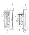
- a housing 590 e.g., an opaque housing, may protect the wire bonds 176 as well as contain an encapsulant material 592.
- a third substrate 530 of an optics stack 540 may extend beyond the first and second substrates 110, 120.
- the third substrate 530 may include features to further aid in restraining the encapsulant 592.
- the resultant stepped structure of optics stack 540 may be formed, for example, by securing the first and second substrates 110, 120 together on a wafer level, singulating the secured pairs, and securing the singulated pairs to the third substrate 530, or by securing all three substrates 110, 120, 530, before singulation, and singulating by dicing, e.g., with different blade widths from different surfaces of the secured substrates.
- the encapsulant 592 may also serve to protect elements of the camera system 500 from moisture and other environmental contaminants.
- Other elements of the fifth embodiment are the same as those in the first embodiment, and detailed description thereof is omitted.
- a housing 690 e.g., an opaque housing, may protect the wire bonds 176 as well as contain an encapsulant material 692.
- a first substrate 610 of an optics stack 640 may have a smaller surface area than the second and third substrates 620, 630.
- the second substrate 620 may include features to further aid in restraining the encapsulant 692.
- the resultant stepped structure of optics stack 640 may be formed, for example, by securing a singulated first substrate to secured second and third substrates or by securing all three substrates before singulation, and singulating by dicing, e.g., with different blade widths from different surfaces of the secured substrates.
- the encapsulant 692 may also serve to hermetically seal the camera system 600.
- the optics stack 640 as with any of the other embodiments, may be any suitable optics stack.
- a stepped optics stack 740 may be used with just an encapsulant 792. This stepped optics stack 740 may help restrain the encapsulant 792 to insure good coverage thereof.
- a first substrate 710 may be smaller than a second substrate 720, which, in turn, may be smaller than a third substrate 730.
- a cover structure 750 may include a concave lens 732 therein.
- the cover structure 750 may include features to further aid in restraining the encapsulant 792.
- the resultant stepped structure of optics stack 740 may be formed, for example, by singulating each of the first through third substrates and then securing then together, singulated the secured pairs or by securing all three substrates before singulation, and singulating by dicing, e.g., with different blade widths from different surfaces of the secured substrates.
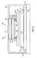
- a camera system 800 according to the eighth embodiment, as illustrated in FIG. 8 may include an optics stack 840 including first through third substrates as in the first embodiment or as in the fifth embodiment.
- spacer 512' between the first and second substrates and spacer 523' between the second and third substrates may not extend to an edge of these substrates. This may be useful when the spacers 512', 523' are not made of materials that typically are subject to singulation, e.g., dicing.
- the spacers 512', 523' are SU8, these spacers 512', 523' may be provided such that they are out of the separation path of their respective substrates.
- An encapsulant 892 may then fill in these gaps between the spacers 512', 523' and an edge of the substrates to reduce stray light.
- the cover structure 150 may include features 158 to restrain the encapsulant 892.
- Exemplary embodiments of the present invention have been disclosed herein, and although specific terms are employed, they are used and are to be interpreted in a generic and descriptive sense only and not for purpose of limitation.
- the substrates in the optics stack may all be the same material or may be different materials.
- the refractive index of the light blocking material may be closest to that of a substrate most likely to internally reflect light or may be averaged across the substrates. Accordingly, it will be understood by those of ordinary skill in the art that various changes in form and details may be made without departing from scope of the present invention as set forth in the following claims.
Claims (13)
- Kamerasystem, umfassend:einen Optikstapel (140, 540) umfassend zwei Substrate (110, 120), die in einer Vertikalrichtung zusammengehalten sind, und ein optisches System (112, 124) auf den zwei Substraten, wobei die zwei Substrate durchsichtige Seiten aufweisen;einen Detektor auf einem Detektorsubstrat (170);dadurch gekennzeichnet, dass das Kamerasystem folgendes umfasst:ein Gehäuse (190, 590), welches den Optikstapel (140, 540) umgibt; undeinen Streulichtblocker umfassend einen Verkapselungsstoff (192, 592) zwischen dem Gehäuse (190, 590) und dem Optikstapel (140, 540), wobei sich der Streulichtblocker auf zumindest einigen durchsichtigen Seiten des Optikstapels befindet.
- Kamerasystem nach Anspruch 1, wobei die zumindest einigen Seiten Seiten auf einem Substrat in dem Optikstapel, der sich von dem Detektorsubstrat am weitesten entfernt befindet, umfassen.
- Kamerasystem nach Anspruch 1, wobei sich der Verkapselungsstoff auf allen durchsichtigen Seiten des Optikstapels befindet.
- Kamerasystem nach Anspruch 1, wobei der Verkapselungsstoff einen Brechungsindex aufweist, welcher dem Brechungsindex eines Substrats, welches die zumindest einigen Seiten aufweist, annähernd gleich ist.
- Kamerasystem nach Anspruch 1, wobei ein Substrat in dem Optikstapel einen kleineren Flächenbereich als das Detektorsubstrat aufweist.
- Kamerasystem nach einem der vorgehenden Ansprüche, wobei der Verkapselungsstoff sich von einer oberen Oberfläche des Optikstapels bis zum Detektorsubstrat erstreckt.
- Kamerasystem nach Anspruch 1, wobei sich das Detektorsubstrat über den Optikstapel hinaus in zumindest eine Richtung erstreckt.
- Kamerasystem nach Anspruch 7, ferner umfassend Klebepads auf dem Detektorsubstrat, welche sich über den Optikstapel hinaus erstrecken.
- Kamerasystem nach Anspruch 8, ferner umfassend ein Substrat, welches mit den Klebepads elektrisch zu verbindende Elemente aufweist.
- Kamerasystem nach Anspruch 9, wobei der Verkapselungsstoff die Klebepads und die elektrischen Verbinder zwischen den Klebepads und dem Detektorsubstrat überdeckt.
- Kamerasystem nach einem der vorgehenden Ansprüche, ferner umfassend Merkmale auf dem Detektorsubstrat, die den Verkapselungsstoff beschränken.
- Kamerasystem nach einem der vorgehenden Ansprüche, wobei das Gehäuse, welches den Optikstapel umgibt, sich nach unten bis zum Detektorsubstrat erstreckt.
- Kamerasystem nach einem der vorgehenden Ansprüche, wobei Substrate in dem Optikstapel nicht flächengleich sind.
Applications Claiming Priority (2)
| Application Number | Priority Date | Filing Date | Title |
|---|---|---|---|
| US11/600,282 US20080118241A1 (en) | 2006-11-16 | 2006-11-16 | Control of stray light in camera systems employing an optics stack and associated methods |
| PCT/US2007/023961 WO2008063528A2 (en) | 2006-11-16 | 2007-11-15 | Control of stray light in camera systems employing an optics stack and associated methods |
Publications (2)
| Publication Number | Publication Date |
|---|---|
| EP2084896A2 EP2084896A2 (de) | 2009-08-05 |
| EP2084896B1 true EP2084896B1 (de) | 2014-10-29 |
Family
ID=39361289
Family Applications (1)
| Application Number | Title | Priority Date | Filing Date |
|---|---|---|---|
| EP07840058.7A Not-in-force EP2084896B1 (de) | 2006-11-16 | 2007-11-15 | Steuerung von streulicht in kamerasystemen mit einem optikstapel und entsprechende verfahren |
Country Status (7)
| Country | Link |
|---|---|
| US (1) | US20080118241A1 (de) |
| EP (1) | EP2084896B1 (de) |
| JP (1) | JP2010510542A (de) |
| KR (1) | KR20090089421A (de) |
| CN (1) | CN101606381B (de) |
| TW (1) | TW200835306A (de) |
| WO (1) | WO2008063528A2 (de) |
Families Citing this family (95)
| Publication number | Priority date | Publication date | Assignee | Title |
|---|---|---|---|---|
| US7961989B2 (en) * | 2001-10-23 | 2011-06-14 | Tessera North America, Inc. | Optical chassis, camera having an optical chassis, and associated methods |
| US7224856B2 (en) * | 2001-10-23 | 2007-05-29 | Digital Optics Corporation | Wafer based optical chassis and associated methods |
| US8546739B2 (en) * | 2007-03-30 | 2013-10-01 | Min-Chih Hsuan | Manufacturing method of wafer level chip scale package of image-sensing module |
| US7528420B2 (en) * | 2007-05-23 | 2009-05-05 | Visera Technologies Company Limited | Image sensing devices and methods for fabricating the same |
| CN101419323A (zh) * | 2007-10-22 | 2009-04-29 | 鸿富锦精密工业(深圳)有限公司 | 微型相机模组及其制作方法 |
| US8217482B2 (en) * | 2007-12-21 | 2012-07-10 | Avago Technologies General Ip (Singapore) Pte. Ltd. | Infrared proximity sensor package with reduced crosstalk |
| US9118825B2 (en) * | 2008-02-22 | 2015-08-25 | Nan Chang O-Film Optoelectronics Technology Ltd. | Attachment of wafer level optics |
| WO2009137022A1 (en) * | 2008-05-06 | 2009-11-12 | Tessera North America, Inc. | Camera system including radiation shield and method of shielding radiation |
| US8866920B2 (en) * | 2008-05-20 | 2014-10-21 | Pelican Imaging Corporation | Capturing and processing of images using monolithic camera array with heterogeneous imagers |
| US11792538B2 (en) | 2008-05-20 | 2023-10-17 | Adeia Imaging Llc | Capturing and processing of images including occlusions focused on an image sensor by a lens stack array |
| JP2011523538A (ja) | 2008-05-20 | 2011-08-11 | ペリカン イメージング コーポレイション | 異なる種類の撮像装置を有するモノリシックカメラアレイを用いた画像の撮像および処理 |
| US7710667B2 (en) * | 2008-06-25 | 2010-05-04 | Aptina Imaging Corp. | Imaging module with symmetrical lens system and method of manufacture |
| GB2465607A (en) * | 2008-11-25 | 2010-05-26 | St Microelectronics | CMOS imager structures |
| US8125720B2 (en) * | 2009-03-24 | 2012-02-28 | Omnivision Technologies, Inc. | Miniature image capture lens |
| CN101872033B (zh) * | 2009-04-24 | 2014-04-30 | 鸿富锦精密工业(深圳)有限公司 | 遮光片阵列、遮光片阵列制造方法及镜头模组阵列 |
| TWM364865U (en) | 2009-05-07 | 2009-09-11 | E Pin Optical Industry Co Ltd | Miniature stacked glass lens module |
| US8420999B2 (en) * | 2009-05-08 | 2013-04-16 | Avago Technologies Ecbu Ip (Singapore) Pte. Ltd. | Metal shield and housing for optical proximity sensor with increased resistance to mechanical deformation |
| US20100295989A1 (en) * | 2009-05-22 | 2010-11-25 | Compal Electronics, Inc. | Image capturing device and manufacturing method of sealing structure |
| US9525093B2 (en) | 2009-06-30 | 2016-12-20 | Avago Technologies General Ip (Singapore) Pte. Ltd. | Infrared attenuating or blocking layer in optical proximity sensor |
| US8957380B2 (en) * | 2009-06-30 | 2015-02-17 | Avago Technologies General Ip (Singapore) Pte. Ltd. | Infrared attenuating or blocking layer in optical proximity sensor |
| US8779361B2 (en) * | 2009-06-30 | 2014-07-15 | Avago Technologies General Ip (Singapore) Pte. Ltd. | Optical proximity sensor package with molded infrared light rejection barrier and infrared pass components |
| US9419032B2 (en) * | 2009-08-14 | 2016-08-16 | Nanchang O-Film Optoelectronics Technology Ltd | Wafer level camera module with molded housing and method of manufacturing |
| US8716665B2 (en) * | 2009-09-10 | 2014-05-06 | Avago Technologies General Ip (Singapore) Pte. Ltd. | Compact optical proximity sensor with ball grid array and windowed substrate |
| US8097852B2 (en) * | 2009-09-10 | 2012-01-17 | Avago Technologies Ecbu Ip (Singapore) Pte. Ltd. | Multiple transfer molded optical proximity sensor and corresponding method |
| US8143608B2 (en) * | 2009-09-10 | 2012-03-27 | Avago Technologies Ecbu Ip (Singapore) Pte. Ltd. | Package-on-package (POP) optical proximity sensor |
| US8350216B2 (en) * | 2009-09-10 | 2013-01-08 | Avago Technologies Ecbu Ip (Singapore) Pte. Ltd. | Miniaturized optical proximity sensor |
| EP2478693B1 (de) * | 2009-09-16 | 2017-04-19 | Medigus Ltd. | Videokameraköpfe und visualisierungssonden von geringem durchmesser und medizinische geräte damit |
| US20140320621A1 (en) | 2009-09-16 | 2014-10-30 | Medigus Ltd. | Small diameter video camera heads and visualization probes and medical devices containing them |
| US8514491B2 (en) * | 2009-11-20 | 2013-08-20 | Pelican Imaging Corporation | Capturing and processing of images using monolithic camera array with heterogeneous imagers |
| US9733357B2 (en) * | 2009-11-23 | 2017-08-15 | Avago Technologies General Ip (Singapore) Pte. Ltd. | Infrared proximity sensor package with improved crosstalk isolation |
| TW201122533A (en) * | 2009-12-30 | 2011-07-01 | Hon Hai Prec Ind Co Ltd | Lens and lens module using same |
| WO2011143501A1 (en) | 2010-05-12 | 2011-11-17 | Pelican Imaging Corporation | Architectures for imager arrays and array cameras |
| US8878950B2 (en) | 2010-12-14 | 2014-11-04 | Pelican Imaging Corporation | Systems and methods for synthesizing high resolution images using super-resolution processes |
| US8841597B2 (en) | 2010-12-27 | 2014-09-23 | Avago Technologies Ip (Singapore) Pte. Ltd. | Housing for optical proximity sensor |
| CN103765864B (zh) | 2011-05-11 | 2017-07-04 | 派力肯影像公司 | 用于传送和接收阵列照相机图像数据的系统和方法 |
| JP2014521117A (ja) | 2011-06-28 | 2014-08-25 | ペリカン イメージング コーポレイション | アレイカメラで使用するための光学配列 |
| US20130265459A1 (en) | 2011-06-28 | 2013-10-10 | Pelican Imaging Corporation | Optical arrangements for use with an array camera |
| WO2013043761A1 (en) | 2011-09-19 | 2013-03-28 | Pelican Imaging Corporation | Determining depth from multiple views of a scene that include aliasing using hypothesized fusion |
| IN2014CN02708A (de) | 2011-09-28 | 2015-08-07 | Pelican Imaging Corp | |
| US9412206B2 (en) | 2012-02-21 | 2016-08-09 | Pelican Imaging Corporation | Systems and methods for the manipulation of captured light field image data |
| JP5851320B2 (ja) | 2012-04-18 | 2016-02-03 | 株式会社東芝 | カメラモジュール |
| US9210392B2 (en) | 2012-05-01 | 2015-12-08 | Pelican Imaging Coporation | Camera modules patterned with pi filter groups |
| US20130341747A1 (en) * | 2012-06-20 | 2013-12-26 | Xintec Inc. | Chip package and method for forming the same |
| EP2873028A4 (de) | 2012-06-28 | 2016-05-25 | Pelican Imaging Corp | Systeme und verfahren zur erkennung defekter kamera-arrays, optischer arrays und sensoren |
| US20140002674A1 (en) | 2012-06-30 | 2014-01-02 | Pelican Imaging Corporation | Systems and Methods for Manufacturing Camera Modules Using Active Alignment of Lens Stack Arrays and Sensors |
| EP2888720B1 (de) | 2012-08-21 | 2021-03-17 | FotoNation Limited | System und verfahren zur tiefenschätzung aus mit array-kameras aufgenommenen bildern |
| EP2888698A4 (de) | 2012-08-23 | 2016-06-29 | Pelican Imaging Corp | Eigenschaftsbasierte hochauflösende bewegungsschätzung aus mit einer arrayquelle aufgenommenen niedrigauflösenden bildern |
| WO2014043641A1 (en) | 2012-09-14 | 2014-03-20 | Pelican Imaging Corporation | Systems and methods for correcting user identified artifacts in light field images |
| CN104685860A (zh) | 2012-09-28 | 2015-06-03 | 派力肯影像公司 | 利用虚拟视点从光场生成图像 |
| JP6145988B2 (ja) * | 2012-10-17 | 2017-06-14 | ミツミ電機株式会社 | カメラモジュール |
| US9143711B2 (en) | 2012-11-13 | 2015-09-22 | Pelican Imaging Corporation | Systems and methods for array camera focal plane control |
| WO2014130849A1 (en) | 2013-02-21 | 2014-08-28 | Pelican Imaging Corporation | Generating compressed light field representation data |
| US9374512B2 (en) | 2013-02-24 | 2016-06-21 | Pelican Imaging Corporation | Thin form factor computational array cameras and modular array cameras |
| US9638883B1 (en) | 2013-03-04 | 2017-05-02 | Fotonation Cayman Limited | Passive alignment of array camera modules constructed from lens stack arrays and sensors based upon alignment information obtained during manufacture of array camera modules using an active alignment process |
| US9774789B2 (en) | 2013-03-08 | 2017-09-26 | Fotonation Cayman Limited | Systems and methods for high dynamic range imaging using array cameras |
| US8866912B2 (en) | 2013-03-10 | 2014-10-21 | Pelican Imaging Corporation | System and methods for calibration of an array camera using a single captured image |
| US9521416B1 (en) | 2013-03-11 | 2016-12-13 | Kip Peli P1 Lp | Systems and methods for image data compression |
| WO2014164550A2 (en) | 2013-03-13 | 2014-10-09 | Pelican Imaging Corporation | System and methods for calibration of an array camera |
| US9106784B2 (en) | 2013-03-13 | 2015-08-11 | Pelican Imaging Corporation | Systems and methods for controlling aliasing in images captured by an array camera for use in super-resolution processing |
| US9519972B2 (en) | 2013-03-13 | 2016-12-13 | Kip Peli P1 Lp | Systems and methods for synthesizing images from image data captured by an array camera using restricted depth of field depth maps in which depth estimation precision varies |
| US9888194B2 (en) | 2013-03-13 | 2018-02-06 | Fotonation Cayman Limited | Array camera architecture implementing quantum film image sensors |
| US9578259B2 (en) | 2013-03-14 | 2017-02-21 | Fotonation Cayman Limited | Systems and methods for reducing motion blur in images or video in ultra low light with array cameras |
| US9100586B2 (en) | 2013-03-14 | 2015-08-04 | Pelican Imaging Corporation | Systems and methods for photometric normalization in array cameras |
| US9445003B1 (en) | 2013-03-15 | 2016-09-13 | Pelican Imaging Corporation | Systems and methods for synthesizing high resolution images using image deconvolution based on motion and depth information |
| WO2014145856A1 (en) | 2013-03-15 | 2014-09-18 | Pelican Imaging Corporation | Systems and methods for stereo imaging with camera arrays |
| US9633442B2 (en) | 2013-03-15 | 2017-04-25 | Fotonation Cayman Limited | Array cameras including an array camera module augmented with a separate camera |
| US9497370B2 (en) | 2013-03-15 | 2016-11-15 | Pelican Imaging Corporation | Array camera architecture implementing quantum dot color filters |
| US10122993B2 (en) | 2013-03-15 | 2018-11-06 | Fotonation Limited | Autofocus system for a conventional camera that uses depth information from an array camera |
| US9497429B2 (en) | 2013-03-15 | 2016-11-15 | Pelican Imaging Corporation | Extended color processing on pelican array cameras |
| JP2016106239A (ja) * | 2013-03-27 | 2016-06-16 | 富士フイルム株式会社 | レンズユニット、撮像モジュール、及び電子機器 |
| CN104297887A (zh) * | 2013-07-17 | 2015-01-21 | 玉晶光电(厦门)有限公司 | 摄影镜头及用于摄影镜头的垫圈 |
| US9898856B2 (en) | 2013-09-27 | 2018-02-20 | Fotonation Cayman Limited | Systems and methods for depth-assisted perspective distortion correction |
| US9426343B2 (en) | 2013-11-07 | 2016-08-23 | Pelican Imaging Corporation | Array cameras incorporating independently aligned lens stacks |
| US10119808B2 (en) | 2013-11-18 | 2018-11-06 | Fotonation Limited | Systems and methods for estimating depth from projected texture using camera arrays |
| US9456134B2 (en) | 2013-11-26 | 2016-09-27 | Pelican Imaging Corporation | Array camera configurations incorporating constituent array cameras and constituent cameras |
| US10089740B2 (en) | 2014-03-07 | 2018-10-02 | Fotonation Limited | System and methods for depth regularization and semiautomatic interactive matting using RGB-D images |
| US9247117B2 (en) | 2014-04-07 | 2016-01-26 | Pelican Imaging Corporation | Systems and methods for correcting for warpage of a sensor array in an array camera module by introducing warpage into a focal plane of a lens stack array |
| US9521319B2 (en) | 2014-06-18 | 2016-12-13 | Pelican Imaging Corporation | Array cameras and array camera modules including spectral filters disposed outside of a constituent image sensor |
| US10250871B2 (en) | 2014-09-29 | 2019-04-02 | Fotonation Limited | Systems and methods for dynamic calibration of array cameras |
| KR102433712B1 (ko) | 2014-10-14 | 2022-08-17 | 에이엠에스 센서스 싱가포르 피티이. 리미티드. | 광학 소자 스택 어셈블리들 |
| US9942474B2 (en) | 2015-04-17 | 2018-04-10 | Fotonation Cayman Limited | Systems and methods for performing high speed video capture and depth estimation using array cameras |
| CN105549173A (zh) | 2016-01-28 | 2016-05-04 | 宁波舜宇光电信息有限公司 | 光学镜头和摄像模组及其组装方法 |
| JPWO2017195302A1 (ja) * | 2016-05-11 | 2019-03-07 | オリンパス株式会社 | レンズユニットの製造方法、及び撮像装置の製造方法 |
| US10482618B2 (en) | 2017-08-21 | 2019-11-19 | Fotonation Limited | Systems and methods for hybrid depth regularization |
| DE102017126215A1 (de) | 2017-11-09 | 2019-05-09 | Delo Industrie Klebstoffe Gmbh & Co. Kgaa | Verfahren zur Erzeugung opaker Beschichtungen, Verklebungen und Vergüsse sowie härtbare Masse zur Verwendung in dem Verfahren |
| WO2019125160A1 (en) | 2017-12-21 | 2019-06-27 | Anteryon Wafer Optics B.V. | Lens system |
| US10935771B2 (en) | 2017-12-21 | 2021-03-02 | Anteryon International B.V. | Lens system |
| US11048067B2 (en) | 2018-05-25 | 2021-06-29 | Anteryon International B.V. | Lens system |
| US11270110B2 (en) | 2019-09-17 | 2022-03-08 | Boston Polarimetrics, Inc. | Systems and methods for surface modeling using polarization cues |
| MX2022004163A (es) | 2019-10-07 | 2022-07-19 | Boston Polarimetrics Inc | Sistemas y metodos para la deteccion de estandares de superficie con polarizacion. |
| JP7329143B2 (ja) | 2019-11-30 | 2023-08-17 | ボストン ポーラリメトリックス,インコーポレイティド | 偏光キューを用いた透明な物体のセグメンテーションのためのシステム及び方法 |
| WO2021154386A1 (en) | 2020-01-29 | 2021-08-05 | Boston Polarimetrics, Inc. | Systems and methods for characterizing object pose detection and measurement systems |
| EP4085424A4 (de) | 2020-01-30 | 2024-03-27 | Intrinsic Innovation Llc | Systeme und verfahren zum synthetisieren von daten für das trainieren von statistischen modellen auf verschiedenen bildgebenden modalitäten, einschliesslich polarisierter bilder |
| US11290658B1 (en) | 2021-04-15 | 2022-03-29 | Boston Polarimetrics, Inc. | Systems and methods for camera exposure control |
| US11689813B2 (en) | 2021-07-01 | 2023-06-27 | Intrinsic Innovation Llc | Systems and methods for high dynamic range imaging using crossed polarizers |
Family Cites Families (30)
| Publication number | Priority date | Publication date | Assignee | Title |
|---|---|---|---|---|
| JPS61129616A (ja) * | 1984-11-28 | 1986-06-17 | Olympus Optical Co Ltd | 内視鏡 |
| JPH08288484A (ja) * | 1995-04-20 | 1996-11-01 | Sony Corp | 固体撮像素子の製造方法 |
| US5815742A (en) * | 1996-06-11 | 1998-09-29 | Minolta Co., Ltd. | Apparatus having a driven member and a drive controller therefor |
| JP3424440B2 (ja) * | 1996-06-11 | 2003-07-07 | ミノルタ株式会社 | 手ブレ補正機能を備えたカメラ |
| JP2000155270A (ja) * | 1998-11-24 | 2000-06-06 | Mitsubishi Cable Ind Ltd | イメージガイド・レンズ構造体 |
| JP3651580B2 (ja) * | 2000-04-07 | 2005-05-25 | 三菱電機株式会社 | 撮像装置及びその製造方法 |
| JP3607160B2 (ja) * | 2000-04-07 | 2005-01-05 | 三菱電機株式会社 | 撮像装置 |
| US6686588B1 (en) * | 2001-01-16 | 2004-02-03 | Amkor Technology, Inc. | Optical module with lens integral holder |
| CN100334503C (zh) * | 2001-02-14 | 2007-08-29 | 株式会社有泽制作所 | 反射型投影屏幕 |
| JP4628618B2 (ja) * | 2001-09-26 | 2011-02-09 | 富士フイルム株式会社 | 撮像光学系 |
| JP2003167102A (ja) * | 2001-12-04 | 2003-06-13 | Sony Corp | 光学素子及びその製造方法 |
| JP3675402B2 (ja) * | 2001-12-27 | 2005-07-27 | セイコーエプソン株式会社 | 光デバイス及びその製造方法、光モジュール、回路基板並びに電子機器 |
| JP2004016410A (ja) * | 2002-06-14 | 2004-01-22 | Fuji Photo Optical Co Ltd | 立体電子内視鏡装置 |
| JP2004029554A (ja) * | 2002-06-27 | 2004-01-29 | Olympus Corp | 撮像レンズユニットおよび撮像装置 |
| JP3907542B2 (ja) * | 2002-07-16 | 2007-04-18 | シャープ株式会社 | 光通信モジュール |
| KR20070096020A (ko) * | 2002-09-17 | 2007-10-01 | 앤터온 비.브이. | 카메라 디바이스, 카메라 디바이스 제조 방법, 웨이퍼스케일 패키지 및 광학 어셈블리 |
| JP2004226873A (ja) * | 2003-01-27 | 2004-08-12 | Sanyo Electric Co Ltd | カメラモジュール及びその製造方法 |
| JP2005116628A (ja) * | 2003-10-03 | 2005-04-28 | Matsushita Electric Ind Co Ltd | 固体撮像装置およびその製造方法 |
| JP2005173265A (ja) * | 2003-12-11 | 2005-06-30 | Canon Inc | 光学素子、光学フィルタ装置及び光学機器 |
| US7880282B2 (en) * | 2003-12-18 | 2011-02-01 | Rf Module & Optical Design Ltd. | Semiconductor package with integrated heatsink and electromagnetic shield |
| DE102004001698A1 (de) * | 2004-01-13 | 2005-08-11 | Robert Bosch Gmbh | Optisches Modul |
| JP2005295050A (ja) * | 2004-03-31 | 2005-10-20 | Miyota Kk | カメラモジュール |
| JP2005317745A (ja) * | 2004-04-28 | 2005-11-10 | Renesas Technology Corp | 固体撮像装置およびその製造方法 |
| JP4365743B2 (ja) * | 2004-07-27 | 2009-11-18 | 富士通マイクロエレクトロニクス株式会社 | 撮像装置 |
| JP4233536B2 (ja) * | 2005-03-31 | 2009-03-04 | シャープ株式会社 | 光学装置用モジュール |
| JP2006294720A (ja) * | 2005-04-07 | 2006-10-26 | Hitachi Maxell Ltd | カメラモジュール |
| JP4254766B2 (ja) * | 2005-09-06 | 2009-04-15 | ミツミ電機株式会社 | カメラモジュール |
| JP4794283B2 (ja) * | 2005-11-18 | 2011-10-19 | パナソニック株式会社 | 固体撮像装置 |
| JP5292291B2 (ja) * | 2006-07-17 | 2013-09-18 | デジタルオプティクス・コーポレイション・イースト | カメラシステムの作製方法 |
| US10949807B2 (en) | 2017-05-04 | 2021-03-16 | Servicenow, Inc. | Model building architecture and smart routing of work items |
-
2006
- 2006-11-16 US US11/600,282 patent/US20080118241A1/en not_active Abandoned
-
2007
- 2007-11-15 JP JP2009537200A patent/JP2010510542A/ja active Pending
- 2007-11-15 CN CN2007800499037A patent/CN101606381B/zh not_active Expired - Fee Related
- 2007-11-15 WO PCT/US2007/023961 patent/WO2008063528A2/en active Application Filing
- 2007-11-15 EP EP07840058.7A patent/EP2084896B1/de not_active Not-in-force
- 2007-11-15 KR KR1020097012362A patent/KR20090089421A/ko not_active Application Discontinuation
- 2007-11-16 TW TW096143796A patent/TW200835306A/zh unknown
Also Published As
| Publication number | Publication date |
|---|---|
| EP2084896A2 (de) | 2009-08-05 |
| TW200835306A (en) | 2008-08-16 |
| CN101606381B (zh) | 2012-06-13 |
| WO2008063528A2 (en) | 2008-05-29 |
| US20080118241A1 (en) | 2008-05-22 |
| JP2010510542A (ja) | 2010-04-02 |
| CN101606381A (zh) | 2009-12-16 |
| WO2008063528A3 (en) | 2008-07-10 |
| KR20090089421A (ko) | 2009-08-21 |
Similar Documents
| Publication | Publication Date | Title |
|---|---|---|
| EP2084896B1 (de) | Steuerung von streulicht in kamerasystemen mit einem optikstapel und entsprechende verfahren | |
| KR100705349B1 (ko) | 고체촬상장치, 반도체 웨이퍼 및 카메라 모듈 | |
| JP4794283B2 (ja) | 固体撮像装置 | |
| US8953087B2 (en) | Camera system and associated methods | |
| US9826131B2 (en) | Compact camera module arrangements that facilitate dam-and-fill and similar encapsulation techniques | |
| JP5498684B2 (ja) | 半導体モジュール及びその製造方法 | |
| US10147750B2 (en) | Optical imaging apparatus and methods of making the same | |
| CN108307095B (zh) | 具有单独遮光的相机的无盖板玻璃阵列相机 | |
| WO2008011003A2 (en) | Camera system and associated methods | |
| US20070019102A1 (en) | Micro camera module and method of manufacturing the same | |
| US10847664B2 (en) | Optical package and method of producing an optical package | |
| WO2010001524A1 (ja) | 固体撮像素子、その製造方法、及び固体撮像装置 | |
| KR101543830B1 (ko) | 광 흡수층을 갖는 이미지 센서 어셈블리용 커버 | |
| US9273999B2 (en) | Spectroscopic sensor | |
| EP3196939A1 (de) | Festkörperabbildungsvorrichtung und herstellungsverfahren dafür | |
| JP4672301B2 (ja) | 固体撮像装置及び固体撮像装置の製造方法 | |
| JP2008250285A (ja) | 光学部材及びそれを備えた撮像デバイス | |
| US10386665B2 (en) | Optical element package | |
| WO2009137022A1 (en) | Camera system including radiation shield and method of shielding radiation | |
| CN113314619B (zh) | 多光谱光学传感器封装结构及其封装方法 | |
| EP3605043A1 (de) | Lichtnachweisvorrichtung | |
| US20100225799A1 (en) | Image pickup unit, method of manufacturing image pickup unit and electronic apparatus provided with image pickup unit | |
| JP2004260356A (ja) | カメラモジュール | |
| US20100044553A1 (en) | Cmos image sensor package and camera module with same | |
| JP2004246220A (ja) | カメラモジュールとその製造方法 |
Legal Events
| Date | Code | Title | Description |
|---|---|---|---|
| PUAI | Public reference made under article 153(3) epc to a published international application that has entered the european phase |
Free format text: ORIGINAL CODE: 0009012 |
|
| 17P | Request for examination filed |
Effective date: 20090616 |
|
| AK | Designated contracting states |
Kind code of ref document: A2 Designated state(s): AT BE BG CH CY CZ DE DK EE ES FI FR GB GR HU IE IS IT LI LT LU LV MC MT NL PL PT RO SE SI SK TR |
|
| DAX | Request for extension of the european patent (deleted) | ||
| 17Q | First examination report despatched |
Effective date: 20111010 |
|
| RAP1 | Party data changed (applicant data changed or rights of an application transferred) |
Owner name: DIGITALOPTICS CORPORATION EAST |
|
| REG | Reference to a national code |
Ref country code: DE Ref legal event code: R079 Ref document number: 602007039073 Country of ref document: DE Free format text: PREVIOUS MAIN CLASS: H04N0005225000 Ipc: H01L0027146000 |
|
| GRAP | Despatch of communication of intention to grant a patent |
Free format text: ORIGINAL CODE: EPIDOSNIGR1 |
|
| RIC1 | Information provided on ipc code assigned before grant |
Ipc: G02B 27/00 20060101ALI20140422BHEP Ipc: H01L 27/146 20060101AFI20140422BHEP Ipc: H04N 5/225 20060101ALI20140422BHEP |
|
| INTG | Intention to grant announced |
Effective date: 20140523 |
|
| RAP1 | Party data changed (applicant data changed or rights of an application transferred) |
Owner name: DIGITALOPTICS CORPORATION |
|
| GRAS | Grant fee paid |
Free format text: ORIGINAL CODE: EPIDOSNIGR3 |
|
| GRAA | (expected) grant |
Free format text: ORIGINAL CODE: 0009210 |
|
| AK | Designated contracting states |
Kind code of ref document: B1 Designated state(s): AT BE BG CH CY CZ DE DK EE ES FI FR GB GR HU IE IS IT LI LT LU LV MC MT NL PL PT RO SE SI SK TR |
|
| REG | Reference to a national code |
Ref country code: GB Ref legal event code: FG4D |
|
| REG | Reference to a national code |
Ref country code: CH Ref legal event code: EP |
|
| REG | Reference to a national code |
Ref country code: AT Ref legal event code: REF Ref document number: 693931 Country of ref document: AT Kind code of ref document: T Effective date: 20141115 |
|
| REG | Reference to a national code |
Ref country code: IE Ref legal event code: FG4D |
|
| REG | Reference to a national code |
Ref country code: DE Ref legal event code: R096 Ref document number: 602007039073 Country of ref document: DE Effective date: 20141211 |
|
| REG | Reference to a national code |
Ref country code: AT Ref legal event code: MK05 Ref document number: 693931 Country of ref document: AT Kind code of ref document: T Effective date: 20141029 |
|
| REG | Reference to a national code |
Ref country code: NL Ref legal event code: VDEP Effective date: 20141029 Ref country code: GB Ref legal event code: 732E Free format text: REGISTERED BETWEEN 20150220 AND 20150225 |
|
| REG | Reference to a national code |
Ref country code: LT Ref legal event code: MG4D |
|
| REG | Reference to a national code |
Ref country code: FR Ref legal event code: TP Owner name: NANCHNAG O-FILM OPTOELECTRONICS TECHNOLOGY LTD, CN Effective date: 20150311 |
|
| PG25 | Lapsed in a contracting state [announced via postgrant information from national office to epo] |
Ref country code: NL Free format text: LAPSE BECAUSE OF FAILURE TO SUBMIT A TRANSLATION OF THE DESCRIPTION OR TO PAY THE FEE WITHIN THE PRESCRIBED TIME-LIMIT Effective date: 20141029 Ref country code: LT Free format text: LAPSE BECAUSE OF FAILURE TO SUBMIT A TRANSLATION OF THE DESCRIPTION OR TO PAY THE FEE WITHIN THE PRESCRIBED TIME-LIMIT Effective date: 20141029 Ref country code: IS Free format text: LAPSE BECAUSE OF FAILURE TO SUBMIT A TRANSLATION OF THE DESCRIPTION OR TO PAY THE FEE WITHIN THE PRESCRIBED TIME-LIMIT Effective date: 20150228 Ref country code: PT Free format text: LAPSE BECAUSE OF FAILURE TO SUBMIT A TRANSLATION OF THE DESCRIPTION OR TO PAY THE FEE WITHIN THE PRESCRIBED TIME-LIMIT Effective date: 20150302 Ref country code: ES Free format text: LAPSE BECAUSE OF FAILURE TO SUBMIT A TRANSLATION OF THE DESCRIPTION OR TO PAY THE FEE WITHIN THE PRESCRIBED TIME-LIMIT Effective date: 20141029 Ref country code: FI Free format text: LAPSE BECAUSE OF FAILURE TO SUBMIT A TRANSLATION OF THE DESCRIPTION OR TO PAY THE FEE WITHIN THE PRESCRIBED TIME-LIMIT Effective date: 20141029 |
|
| PG25 | Lapsed in a contracting state [announced via postgrant information from national office to epo] |
Ref country code: PL Free format text: LAPSE BECAUSE OF FAILURE TO SUBMIT A TRANSLATION OF THE DESCRIPTION OR TO PAY THE FEE WITHIN THE PRESCRIBED TIME-LIMIT Effective date: 20141029 Ref country code: LV Free format text: LAPSE BECAUSE OF FAILURE TO SUBMIT A TRANSLATION OF THE DESCRIPTION OR TO PAY THE FEE WITHIN THE PRESCRIBED TIME-LIMIT Effective date: 20141029 Ref country code: AT Free format text: LAPSE BECAUSE OF FAILURE TO SUBMIT A TRANSLATION OF THE DESCRIPTION OR TO PAY THE FEE WITHIN THE PRESCRIBED TIME-LIMIT Effective date: 20141029 Ref country code: CY Free format text: LAPSE BECAUSE OF FAILURE TO SUBMIT A TRANSLATION OF THE DESCRIPTION OR TO PAY THE FEE WITHIN THE PRESCRIBED TIME-LIMIT Effective date: 20141029 Ref country code: GR Free format text: LAPSE BECAUSE OF FAILURE TO SUBMIT A TRANSLATION OF THE DESCRIPTION OR TO PAY THE FEE WITHIN THE PRESCRIBED TIME-LIMIT Effective date: 20150130 Ref country code: SE Free format text: LAPSE BECAUSE OF FAILURE TO SUBMIT A TRANSLATION OF THE DESCRIPTION OR TO PAY THE FEE WITHIN THE PRESCRIBED TIME-LIMIT Effective date: 20141029 |
|
| REG | Reference to a national code |
Ref country code: DE Ref legal event code: R082 Ref document number: 602007039073 Country of ref document: DE Representative=s name: MICHALSKI HUETTERMANN & PARTNER PATENTANWAELTE, DE Ref country code: DE Ref legal event code: R081 Ref document number: 602007039073 Country of ref document: DE Owner name: NANCHANG O-FILM OPTOELECTRONICS TECHNOLOGY LTD, CN Free format text: FORMER OWNER: DIGITALOPTICS CORPORATION, SAN JOSE, CALIF., US |
|
| PG25 | Lapsed in a contracting state [announced via postgrant information from national office to epo] |
Ref country code: BE Free format text: LAPSE BECAUSE OF NON-PAYMENT OF DUE FEES Effective date: 20141130 |
|
| REG | Reference to a national code |
Ref country code: CH Ref legal event code: PL |
|
| REG | Reference to a national code |
Ref country code: DE Ref legal event code: R097 Ref document number: 602007039073 Country of ref document: DE |
|
| PG25 | Lapsed in a contracting state [announced via postgrant information from national office to epo] |
Ref country code: RO Free format text: LAPSE BECAUSE OF FAILURE TO SUBMIT A TRANSLATION OF THE DESCRIPTION OR TO PAY THE FEE WITHIN THE PRESCRIBED TIME-LIMIT Effective date: 20141029 Ref country code: LI Free format text: LAPSE BECAUSE OF NON-PAYMENT OF DUE FEES Effective date: 20141130 Ref country code: SK Free format text: LAPSE BECAUSE OF FAILURE TO SUBMIT A TRANSLATION OF THE DESCRIPTION OR TO PAY THE FEE WITHIN THE PRESCRIBED TIME-LIMIT Effective date: 20141029 Ref country code: CZ Free format text: LAPSE BECAUSE OF FAILURE TO SUBMIT A TRANSLATION OF THE DESCRIPTION OR TO PAY THE FEE WITHIN THE PRESCRIBED TIME-LIMIT Effective date: 20141029 Ref country code: CH Free format text: LAPSE BECAUSE OF NON-PAYMENT OF DUE FEES Effective date: 20141130 Ref country code: MC Free format text: LAPSE BECAUSE OF FAILURE TO SUBMIT A TRANSLATION OF THE DESCRIPTION OR TO PAY THE FEE WITHIN THE PRESCRIBED TIME-LIMIT Effective date: 20141029 Ref country code: EE Free format text: LAPSE BECAUSE OF FAILURE TO SUBMIT A TRANSLATION OF THE DESCRIPTION OR TO PAY THE FEE WITHIN THE PRESCRIBED TIME-LIMIT Effective date: 20141029 Ref country code: DK Free format text: LAPSE BECAUSE OF FAILURE TO SUBMIT A TRANSLATION OF THE DESCRIPTION OR TO PAY THE FEE WITHIN THE PRESCRIBED TIME-LIMIT Effective date: 20141029 |
|
| REG | Reference to a national code |
Ref country code: IE Ref legal event code: MM4A |
|
| PG25 | Lapsed in a contracting state [announced via postgrant information from national office to epo] |
Ref country code: IT Free format text: LAPSE BECAUSE OF FAILURE TO SUBMIT A TRANSLATION OF THE DESCRIPTION OR TO PAY THE FEE WITHIN THE PRESCRIBED TIME-LIMIT Effective date: 20141029 |
|
| PLBE | No opposition filed within time limit |
Free format text: ORIGINAL CODE: 0009261 |
|
| STAA | Information on the status of an ep patent application or granted ep patent |
Free format text: STATUS: NO OPPOSITION FILED WITHIN TIME LIMIT |
|
| 26N | No opposition filed |
Effective date: 20150730 |
|
| PG25 | Lapsed in a contracting state [announced via postgrant information from national office to epo] |
Ref country code: IE Free format text: LAPSE BECAUSE OF NON-PAYMENT OF DUE FEES Effective date: 20141115 |
|
| REG | Reference to a national code |
Ref country code: FR Ref legal event code: PLFP Year of fee payment: 9 |
|
| PGFP | Annual fee paid to national office [announced via postgrant information from national office to epo] |
Ref country code: GB Payment date: 20151118 Year of fee payment: 9 Ref country code: DE Payment date: 20151119 Year of fee payment: 9 |
|
| PG25 | Lapsed in a contracting state [announced via postgrant information from national office to epo] |
Ref country code: SI Free format text: LAPSE BECAUSE OF FAILURE TO SUBMIT A TRANSLATION OF THE DESCRIPTION OR TO PAY THE FEE WITHIN THE PRESCRIBED TIME-LIMIT Effective date: 20141029 |
|
| PGFP | Annual fee paid to national office [announced via postgrant information from national office to epo] |
Ref country code: FR Payment date: 20151119 Year of fee payment: 9 |
|
| PG25 | Lapsed in a contracting state [announced via postgrant information from national office to epo] |
Ref country code: BG Free format text: LAPSE BECAUSE OF FAILURE TO SUBMIT A TRANSLATION OF THE DESCRIPTION OR TO PAY THE FEE WITHIN THE PRESCRIBED TIME-LIMIT Effective date: 20141029 |
|
| PG25 | Lapsed in a contracting state [announced via postgrant information from national office to epo] |
Ref country code: MT Free format text: LAPSE BECAUSE OF FAILURE TO SUBMIT A TRANSLATION OF THE DESCRIPTION OR TO PAY THE FEE WITHIN THE PRESCRIBED TIME-LIMIT Effective date: 20141029 Ref country code: TR Free format text: LAPSE BECAUSE OF FAILURE TO SUBMIT A TRANSLATION OF THE DESCRIPTION OR TO PAY THE FEE WITHIN THE PRESCRIBED TIME-LIMIT Effective date: 20141029 Ref country code: HU Free format text: LAPSE BECAUSE OF FAILURE TO SUBMIT A TRANSLATION OF THE DESCRIPTION OR TO PAY THE FEE WITHIN THE PRESCRIBED TIME-LIMIT; INVALID AB INITIO Effective date: 20071115 Ref country code: LU Free format text: LAPSE BECAUSE OF NON-PAYMENT OF DUE FEES Effective date: 20141115 |
|
| REG | Reference to a national code |
Ref country code: DE Ref legal event code: R119 Ref document number: 602007039073 Country of ref document: DE |
|
| GBPC | Gb: european patent ceased through non-payment of renewal fee |
Effective date: 20161115 |
|
| REG | Reference to a national code |
Ref country code: FR Ref legal event code: ST Effective date: 20170731 |
|
| PG25 | Lapsed in a contracting state [announced via postgrant information from national office to epo] |
Ref country code: FR Free format text: LAPSE BECAUSE OF NON-PAYMENT OF DUE FEES Effective date: 20161130 |
|
| PG25 | Lapsed in a contracting state [announced via postgrant information from national office to epo] |
Ref country code: GB Free format text: LAPSE BECAUSE OF NON-PAYMENT OF DUE FEES Effective date: 20161115 Ref country code: DE Free format text: LAPSE BECAUSE OF NON-PAYMENT OF DUE FEES Effective date: 20170601 |