EP3165151A1 - Dispositif de tomographie - Google Patents
Dispositif de tomographie Download PDFInfo
- Publication number
- EP3165151A1 EP3165151A1 EP15814335.4A EP15814335A EP3165151A1 EP 3165151 A1 EP3165151 A1 EP 3165151A1 EP 15814335 A EP15814335 A EP 15814335A EP 3165151 A1 EP3165151 A1 EP 3165151A1
- Authority
- EP
- European Patent Office
- Prior art keywords
- image capturing
- tomographic
- mode
- capturing mode
- scans
- Prior art date
- Legal status (The legal status is an assumption and is not a legal conclusion. Google has not performed a legal analysis and makes no representation as to the accuracy of the status listed.)
- Withdrawn
Links
Images


Classifications
-
- A—HUMAN NECESSITIES
- A61—MEDICAL OR VETERINARY SCIENCE; HYGIENE
- A61B—DIAGNOSIS; SURGERY; IDENTIFICATION
- A61B3/00—Apparatus for testing the eyes; Instruments for examining the eyes
- A61B3/10—Objective types, i.e. instruments for examining the eyes independent of the patients' perceptions or reactions
- A61B3/102—Objective types, i.e. instruments for examining the eyes independent of the patients' perceptions or reactions for optical coherence tomography [OCT]
-
- A—HUMAN NECESSITIES
- A61—MEDICAL OR VETERINARY SCIENCE; HYGIENE
- A61B—DIAGNOSIS; SURGERY; IDENTIFICATION
- A61B3/00—Apparatus for testing the eyes; Instruments for examining the eyes
- A61B3/0016—Operational features thereof
- A61B3/0025—Operational features thereof characterised by electronic signal processing, e.g. eye models
-
- A—HUMAN NECESSITIES
- A61—MEDICAL OR VETERINARY SCIENCE; HYGIENE
- A61B—DIAGNOSIS; SURGERY; IDENTIFICATION
- A61B3/00—Apparatus for testing the eyes; Instruments for examining the eyes
- A61B3/0016—Operational features thereof
- A61B3/0041—Operational features thereof characterised by display arrangements
-
- A—HUMAN NECESSITIES
- A61—MEDICAL OR VETERINARY SCIENCE; HYGIENE
- A61B—DIAGNOSIS; SURGERY; IDENTIFICATION
- A61B3/00—Apparatus for testing the eyes; Instruments for examining the eyes
- A61B3/10—Objective types, i.e. instruments for examining the eyes independent of the patients' perceptions or reactions
- A61B3/1025—Objective types, i.e. instruments for examining the eyes independent of the patients' perceptions or reactions for confocal scanning
-
- G—PHYSICS
- G01—MEASURING; TESTING
- G01B—MEASURING LENGTH, THICKNESS OR SIMILAR LINEAR DIMENSIONS; MEASURING ANGLES; MEASURING AREAS; MEASURING IRREGULARITIES OF SURFACES OR CONTOURS
- G01B9/00—Measuring instruments characterised by the use of optical techniques
- G01B9/02—Interferometers
- G01B9/02041—Interferometers characterised by particular imaging or detection techniques
- G01B9/02048—Rough and fine measurement
-
- G—PHYSICS
- G01—MEASURING; TESTING
- G01B—MEASURING LENGTH, THICKNESS OR SIMILAR LINEAR DIMENSIONS; MEASURING ANGLES; MEASURING AREAS; MEASURING IRREGULARITIES OF SURFACES OR CONTOURS
- G01B9/00—Measuring instruments characterised by the use of optical techniques
- G01B9/02—Interferometers
- G01B9/0209—Low-coherence interferometers
- G01B9/02091—Tomographic interferometers, e.g. based on optical coherence
Definitions
- the present invention relates to a tomographic image capturing device that captures a tomographic image of an object such as a subject's eye on the basis of interference light generated by superposition of measurement light from the object and reference light.
- tomographic image capturing devices that utilize optical interference of so-called OCT (Optical Coherence Tomography) to capture tomographic images of ocular fundi.
- OCT Optical Coherence Tomography
- Such tomographic image capturing devices can capture tomographic images of ocular fundi at high sensitivity through irradiating the ocular fundi with broadband and low coherent light and causing the reflected light from the ocular fundi to interfere with reference light.
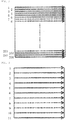
- the horizontal direction, vertical direction and depth of an ocular fundus are represented by x-direction, y-direction and z-direction, respectively, such a tomographic image capturing device can acquire tomographic pictures (B-scan pictures)
- the tomographic images are captured, for example, at a rate of 40 images per second and a set of 100 or more tomographic pictures of a retina can be acquired by one-time testing (image capturing at a part of the retina).
- adjustment of an image capturing condition such as positioning of an image capturing site and reference mirror, focus adjustment, and determination of a dispersion compensation glass, may be performed before the image capturing so that optimum tomographic pictures of an ocular fundus are obtained. As illustrated in FIG.
- the raster scan area as a whole is scanned as in the capturing of tomographic images, all of the tomographic pictures of the image capturing site can be observed during the adjustment of the image capturing condition and an optimum image capturing condition can thus be determined.
- This is said to be ideal.
- the raster scans of the scanning area as a whole take time and the adjustment of image capturing condition accordingly requires a long period of time.
- the actual capturing of tomographic images is after performing adjustment of the image capturing condition to optimize the image capturing condition, and the sequence of image capturing operations takes time, which may restrain the subject from moving until the image capturing is completed.
- the image capturing operations may readily be affected by the disturbance such as involuntary eye movements. If large involuntary eye movements occur, adjustment of the image capturing condition will be necessary again. This may lead to a negative spiral that the image capturing requires a longer period of time.
- the present invention has been made in consideration of the above and an object of the present invention is to provide a tomographic image capturing device that can complete adjustment of the image capturing condition in a short time to determine an optimum image capturing condition.
- the present invention provides a tomographic image capturing device configured to: split light from a light source into measurement light and reference light; cause the measurement light and the reference light to be incident to an object and a reference object, respectively; and capture tomographic images of the object on the basis of interference light generated by superposition of the measurement light reflected from the object and the reference light reflected from the reference object, the tomographic image capturing device having a first image capturing mode and a second image capturing mode, the first and second image capturing modes each being a mode in which the measurement light is two-dimensionally scanned to be incident to the object and the tomographic images of the object are captured, the two-dimensional scans in the second image capturing mode requiring a shorter time than that required for the two-dimensional scans in the first image capturing mode, the capturing of the tomographic images in the first image capturing mode being performed after performing adjustment of an image capturing condition necessary for capturing the tomographic images in the first image capturing mode, the adjustment being based on the tom
- examples of adjustment of the image capturing condition necessary for capturing tomographic images in the first image capturing mode include various adjustment operations that are performed before the capturing of tomographic images to obtain optimum tomographic pictures of an ocular fundus, such as alignment of the tomographic image capturing device and a subject's eye as the object, focus adjustment to move the position of a focusing lens for focusing in accordance with the diopter scale of a subject's eye, reference mirror positioning to move the position of a reference mirror to match the optical path lengths of the measurement optical system and reference optical system so that interference light is generated by superposition of the measurement light and reference light, and dispersion compensation glass determination to select an appropriate dispersion compensation glass for compensating for refractive index dispersion that causes blurred tomographic images.
- the second image capturing mode is provided to capture tomographic images by the two-dimensional scans which require a shorter time than that in the first image capturing mode and therefore the adjustment of the image capturing condition can be completed in a short time by performing, in the second image capturing mode, the adjustment of image capturing condition necessary for capturing tomographic images in the first image capturing mode.
- an optimum image capturing condition can be determined because the capturing of tomographic images in the second image capturing mode is performed by the two-dimensional scans, rather than by the one-dimensional scan at the center position or the like of the raster scans as in the prior art, and tomographic pictures that almost entirely cover the image capturing site can thereby be observed during the adjustment of image capturing condition.
- the scanning region in the second image capturing mode is preferably a region that includes a region of interest within the scanning region in the first image capturing mode (Invention 2).
- the "region of interest” as used herein refers to a region that represents a change in form of the image capturing object within the scanning region in the first image capturing mode.
- the region of interest within a target region to be scanned is included in a target to be scanned in the second image capturing mode. Therefore, information sufficient to adjust the image capturing condition necessary when capturing the tomographic images in the first image capturing mode can be obtained from the tomographic images captured in the second image capturing mode.
- the scanning region in the second image capturing mode may be wider than or narrower than the scanning region in the first image capturing mode, provided that the scanning region in the second image capturing mode includes the region of interest within the scanning region in the first image capturing mode.
- the two-dimensional scans in the first image capturing mode are preferably raster scans (Invention 3).
- the two-dimensional scans in the second image capturing mode are preferably scans thinned from the raster scans in the first image capturing mode (Invention 4).
- the scans may be scans that scan four sides of a rectangular region including the region of interest within the scanning region in the first image capturing mode (Invention 5) or may also be scans that scan one or two diagonals of a rectangular region including the region of interest within the scanning region in the first image capturing mode (Invention 6).
- the tomographic image capturing device may further have a third image capturing mode in which the measurement light is one-dimensionally scanned to be incident to the object and a tomographic image of the object is captured, wherein a first adjustment operation may be performed on the basis of the tomographic image captured in the third image capturing mode and a second adjustment operation may then be performed on the basis of the tomographic images captured in the second image capturing mode (Invention 7), or the tomographic image capturing device may include a display means that displays tomographic pictures of the object generated on the basis of the captured tomographic images, wherein the display means may be configured to be switchable between a first display mode and a second display mode in the second image capturing mode, wherein the first display mode may be a mode in which only one tomographic picture including a certain position of interest of the object is displayed from among the tomographic pictures generated on the basis of the tomographic images captured in the second image capturing mode and the second display mode may be a mode in which the to
- the first adjustment operation means performing dispersion compensation glass determination to select an appropriate dispersion compensation glass in order to compensate for refractive index dispersion that causes blurred tomographic images and performing focus adjustment to move the position of a focusing lens for focusing in accordance with the diopter scale of a subject's eye.
- the second adjustment operation means performing focus adjustment to move the position of a focusing lens for focusing in accordance with the diopter scale of a subject's eye and performing reference mirror positioning to move the position of a reference mirror to match the optical path lengths of the measurement optical system and reference optical system so that interference light is generated by superposition of the measurement light and reference light.
- the first adjustment operation in which the adjustment can be appropriately performed on the basis only of a specific tomographic picture
- the second adjustment operation in which the adjustment can be more appropriately performed rather on the basis of a plurality of tomographic pictures obtained through the two-dimensional scans, can be separately performed, and a more appropriate image capturing condition can thereby be determined in a short time.
- the tomographic image capturing device preferably includes a storage means that stores the tomographic images captured in the second image capturing mode (Invention 9).
- a storage means that stores the tomographic images captured in the second image capturing mode (Invention 9).
- tomographic images acquired for adjustment of the image capturing condition have not been used for other purposes than the adjustment, but according to the above invention (Invention 9), data of the tomographic images captured in the second image capturing mode can be stored and the stored data can thus be used for correction of the positioning of the tomographic pictures generated from the tomographic images captured in the first image capturing mode and/or used as thumbnail pictures.
- adjustment of the image capturing condition can be completed in a short time to determine an optimum image capturing condition.
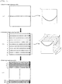
- FIG. 1 is an optics view illustrating the overall configuration of a tomographic image capturing device according to the first embodiment of the present invention.
- the tomographic image capturing device according to the present embodiment which can be applied to an ocular fundus of a subject's eye E as the image capturing object, is to capture tomographic images of a desired region of the ocular fundus by raster scans.
- the part denoted by reference numeral 10 is a demultiplexing/multiplexing optical system.
- This optical system may be provided with a broadband low-coherence light source 11 that comprises, for example, a super-luminescent diode (SLD) and emits light of a temporal coherence length of about several micrometers to several tens of micrometers at a wavelength of 700 nm to 1,100 nm.
- a broadband low-coherence light source 11 that comprises, for example, a super-luminescent diode (SLD) and emits light of a temporal coherence length of about several micrometers to several tens of micrometers at a wavelength of 700 nm to 1,100 nm.
- SLD super-luminescent diode
- the low-coherence light generated from the low-coherence light source 11 passes through a light power adjustment mechanism 12, in which the light power is adjusted, and is incident to an optical coupler 13 via an optical fiber 13a and then introduced into a beam splitter 20 as a splitting optical element via an optical fiber 13b and collimator lens 14. Demultiplexing and/or multiplexing may also be performed using an optical circulator as substitute for the optical coupler 13.
- the light incident to the beam splitter 20 is split into reference light and measurement light.
- the measurement light is incident to a focusing lens 31, which is to focus the measurement light on the ocular fundus of the subject's eye E.
- the measurement light to be focused on the ocular fundus is reflected by a mirror 32, passes through a lens 33, and is scanned in an arbitrary direction by an x-axis scanning mirror (galvanometer mirror) 34 and y-axis scanning mirror (galvanometer mirror) 35.
- the measurement light scanned by the x-axis and y-axis scanning mirrors 34 and 35 passes through a scanning lens 36, is reflected by a dichroic mirror 37, and then passes through an objective lens 38 to be incident to the ocular fundus, which is thus scanned by the measurement light in the x-direction and y-direction.
- the measurement light reflected by the ocular fundus tracks back the above path to return to the beam splitter 20.
- the focusing lens 31, mirror 32, lens 33, x-axis scanning mirror 34, y-axis scanning mirror 35, scanning lens 36, dichroic mirror 37 and objective lens 38 which are located downstream the beam splitter 20, may constitute a measurement optical system 30 of the tomographic image capturing device.
- the reference light split by the beam splitter 20 is reflected by a mirror 41 and then passes through a dispersion compensation glass for objective lens 42 and lenses 43 and 44. Thereafter, the reference light is reflected by a mirror 45 and passes through a subject's eye dispersion compensation glass 50 that compensates for the refractive index dispersion of the subject's eye E as the object. Then, the reference light is reflected by a dichroic mirror 46, passes through a focusing lens 47 and variable aperture 48, and reaches a reference mirror 49.
- the variable aperture 48 may adjust the light power.
- the focusing lens 47, variable aperture 48 and reference mirror 49 can move in the optical axis direction in an integrated manner, as indicated by the horizontal arrow in FIG. 1 .
- the reference light reflected by the reference mirror 49 tracks back the above optical path to return to the beam splitter 20.
- the focusing lens 31, lens 33, scanning lens 36 and objective lens 38 of the measurement optical system 30 may correspond respectively to the lens 43, lens 44, focusing lens 47 and dispersion compensation glass for objective lens 42 of the reference optical system 40, and respective dispersion characteristics may be the same or equivalent.
- the mirror 32, x-axis scanning mirror 34, y-axis scanning mirror 35 and dichroic mirror 37 of the measurement optical system 30 may correspond respectively to the mirror 41, mirror 45, reference mirror 49 and dichroic mirror 46 of the reference optical system 40, and respective dispersion characteristics may also be the same or equivalent.
- the dispersion characteristics of the subject's eye E and the dispersion characteristics of the subject's eye dispersion compensation glass 50 may also be the same or equivalent.
- the mirror 41, dispersion compensation glass for objective lens 42, lenses 43 and 44, mirror 45, subject's eye dispersion compensation glass 50, dichroic mirror 46, focusing lens 47 and reference mirror 49 may constitute a reference optical system 40 of the tomographic image capturing device.
- the reference mirror 49 may act as a reference object.
- the measurement light and reference light returned to the beam splitter 20 are superposed with each other to be interference light, which passes through the collimator lens 14 and optical coupler 13 and is incident to a spectroscope 16 via an optical fiber 13c.
- the spectroscope 16 may have a diffraction grating 16a, imaging lens 16b, line sensor 16c, and other necessary components.
- the interference light is diffracted by the diffraction grating 16a into a spectrum in accordance with the wavelength of the low-coherence light and forms an image on the line sensor 16c by the imaging lens 16b.
- Signals from the line sensor 16c may be subjected to signal processing, including Fourier transformation, performed by a tomographic picture forming means that is realized using one or more CPUs of a computer 17 and the like.
- This signal processing generates a depth signal that represents information in the depth direction (z-direction) of the ocular fundus.
- the interference light at each sampling time point allows the depth signal (A-scan picture) at the sampling time point to be obtained. Therefore, completion of one scanning can form a two-dimensional tomographic picture (B-scan picture) that comprises a z-direction picture (A-scan picture) along the scanning direction.
- the formed tomographic picture (B-scan picture) can be displayed on the display 18.
- the formed tomographic picture can also be stored in a storage part (not illustrated) of the computer 17.
- the tomographic image capturing device may perform some adjustments of the image capturing condition to optimize the image capturing condition when actually capturing tomographic images.
- adjustments of the image capturing condition include, for example, alignment of the tomographic image capturing device and the subject's eye E as the object, focus adjustment to move the position of the focusing lens 31 for focusing in accordance with the diopter scale of the subject's eye E, reference mirror positioning to move the position of the reference mirror 49 to match the optical path lengths of the measurement optical system and reference optical system so that interference light is generated by superposition of the measurement light and reference light, and dispersion compensation glass determination to select an appropriate dispersion compensation glass 50 for compensating for refractive index dispersion that causes blurred tomographic images.
- the tomographic image capturing device may be configured to be switchable between a preliminary image capturing mode (second image capturing mode) and a main image capturing mode (first image capturing mode).
- a preliminary image capturing mode tomographic images for adjusting the image capturing condition are captured.
- the main image capturing mode tomographic images for actually obtaining tomographic pictures of a desired region (scanning region) of the ocular fundus are obtained after an optimum image capturing condition is determined by the adjustment of image capturing condition.
- the tomographic image capturing device may capture tomographic images using different scanning patterns in the preliminary image capturing mode and in the main image capturing mode and can switch between the preliminary image capturing mode and the main image capturing mode by an image capturing mode switching operation.
- the scanning region as a whole may be raster-scanned.
- the scans may be performed 256 times in total in the fast axis direction (x-direction), but are not limited thereto and may be appropriately modified in accordance with the image capturing object, purpose of image capturing, and/or size of the scanning region.
- the scanning interval in the slow axis direction (y-direction) may be extended thereby to perform scans of a coarser scanning density than that in the main image capturing mode, that is, to perform scans thinned from the scans in the fast axis direction (x-direction) of the raster scans in the main image capturing mode.
- the scans may be performed 11 times in total in the fast axis direction (x-direction), but are not limited thereto and may be appropriately modified in accordance with the image capturing object, purpose of image capturing, and/or size of the scanning region.
- the number of scans in the preliminary image capturing mode may preferably be set within a range of 1/2 to 1/20 of the number of scans in the main image capturing mode because the preliminary image capturing mode is expected to have an effect of reducing the time required for capturing the tomographic images for adjustment of the image capturing condition by making the scanning density coarser than that in the main image capturing mode, that is, an effect of completing the adjustment of image capturing condition in a short time.
- the scanning region in the preliminary image capturing mode may be a region that is the same as the scanning region in the main image capturing mode. Therefore, the region of interest within the scanning region in the main image capturing mode is included in the scanning region in the preliminary image capturing mode, as will be understood.
- the region of interest refers to a region that represents a change in form of the image capturing object (ocular fundus of the subject's eye E) within the scanning region in the main image capturing mode.
- the selective display mode refers to a display scheme in which the display 18 displays only one tomographic picture including a certain position of interest of the object from among the tomographic pictures generated on the basis of the tomographic images captured in the preliminary image capturing mode.
- the sequential display mode refers to a display scheme in which the tomographic pictures generated on the basis of the tomographic images captured in the preliminary image capturing mode are in turn sequentially displayed on the display 18.
- 11 tomographic pictures generated on the basis of the tomographic images captured through all the scans may be in turn displayed in a repetitive manner.
- the adjustment of image capturing condition may be divided into two stages of a first adjustment operation and a second adjustment operation, and the previously-described selective display mode may be used to perform the first adjustment operation while the sequential display mode may be used to perform the second adjustment operation.
- the first adjustment operation may include performing dispersion compensation glass determination to select an appropriate dispersion compensation glass 50 in order to compensate for refractive index dispersion that causes blurred tomographic images and performing focus adjustment to move the position of the focusing lens 31 for focusing in accordance with the diopter scale of the subject's eye E.
- the second adjustment operation may include performing focus adjustment to move the position of the focusing lens 31 for focusing in accordance with the diopter scale of the subject's eye E and performing reference mirror positioning to move the position of the reference mirror 49 to match the optical path lengths of the measurement optical system and reference optical system so that interference light is generated by superposition of the measurement light and reference light.
- the first adjustment operation in which the adjustment can be appropriately performed on the basis only of the one specific tomographic picture
- the second adjustment operation in which the adjustment can be more appropriately performed rather on the basis of the plurality of tomographic pictures obtained through the two-dimensional scans, can be separately performed, and a more appropriate image capturing condition can thereby be determined in a short time.
- the first adjustment operation may be performed in the preliminary image capturing mode, but the first adjustment operation is capable of appropriate adjustment based only on the one specific tomographic picture.
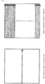
- the display 18 may be set in the selective display mode and repeatedly display only a tomographic picture T 6 that is generated on the basis of the tomographic image captured by the scan of No. 6.
- the image capturing scheme may remain in the preliminary image capturing mode while the display mode switching button may be pressed to switch the display 18 to the sequential display mode to perform the second adjustment operation in which, as illustrated in FIG. 4(b) , the adjustment can be more appropriately performed rather on the basis of the plurality of tomographic pictures obtained through the two-dimensional scans.
- the sequential display mode the tomographic images T 1 to T 11 may be in turn displayed in a repetitive manner.
- the display mode switching button may be pressed to switch from the preliminary image capturing mode to the main image capturing mode in which, as illustrated in FIG. 4(c) , 256 raster scans in total may be performed in the fast axis direction (x-direction) within the entire scanning region to capture tomographic images of the ocular fundus of the subject's eye E under the optimized image capturing condition.
- the selective display mode and the sequential display mode are merely different in the display scheme for the tomographic pictures.
- the image capturing itself of tomographic images of the subject's eye E may be performed through 11 scans in total of No. 1 to No. 11 under the preliminary image capturing mode.
- scans of No. 1 to No. 11 may be performed to capture the tomographic images necessary for generating the tomographic pictures T 1 to T11, rather than performing only the scan of No. 6 to capture only the tomographic image for generating the tomographic picture T 6 .
- Data of the tomographic images captured in the preliminary image capturing mode and the tomographic pictures generated based thereon may be stored in a storage part (not illustrated) of the computer 17.
- the tomographic pictures acquired by image capturing in the preliminary image capturing mode are those obtained through raster scans at a speed of several times to several tens of times higher than that for the tomographic pictures obtained by image capturing in the main image capturing mode. Therefore, image capturing is possible while suppressing the position shift due to involuntary eye movements in the slow axis direction.
- Each tomographic picture acquired in the preliminary image capturing mode can be used as the basis to perform correction of the position shift for relocation of the tomographic pictures acquired in the first image capturing mode and it is thus possible to obtain high-density pictures from which the influence of involuntary eye movements is eliminated.
- the preliminary image capturing mode is provided to capture tomographic images through the two-dimensional scans in which the scanning density is coarser than that in the main image capturing mode, and the time required for the two-dimensional scans in the preliminary image capturing mode can be shorter than that for the two-dimensional scans in the main image capturing mode. Therefore, the adjustment of image capturing condition can be completed in a short time by performing, in the preliminary image capturing mode, the adjustment of image capturing condition necessary for capturing tomographic images in the main image capturing mode.
- an optimum image capturing condition can be determined because the capturing of tomographic images in the preliminary image capturing mode is performed through the two-dimensional scans, though with a coarse scanning density, rather than through one-dimensional scan at the center position or the like of raster scans as in the prior art, and tomographic pictures that almost entirely cover the image capturing site can thereby be observed during the adjustment of image capturing condition.
- the overall configuration of the tomographic image capturing device according to the second embodiment is identical to that of the tomographic image capturing device according to the first embodiment and the description of the optical systems and others will be omitted.
- the same or similar elements, components and devices as in the first embodiment are denoted by the same reference numerals and the same term is used as having the same meaning. Different aspects from those of the tomographic image capturing device according to the first embodiment will be described below.
- the adjustment of image capturing condition is divided into a first adjustment operation and a second adjustment operation.
- the tomographic image capturing device is configured to be switchable among an adjustive image capturing mode in which a tomographic image for performing the first adjustment operation is captured, a preliminary image capturing mode in which tomographic images for performing the second adjustment operation are captured, and a main image capturing operation in which tomographic images for actually obtaining tomographic pictures of a scanning region are captured after an optimum image capturing condition is determined by the first and second adjustment operations.
- the tomographic image capturing device can capture tomographic images using different scanning patterns in these modes and switch among the adjustive image capturing mode, the preliminary image capturing mode and the main image capturing mode by an image capturing mode switching operation.
- the scanning patterns in the preliminary image capturing mode and in the main image capturing mode are the same as those of the first embodiment.
- the adjustive image capturing mode is an image capturing mode in which the measurement light is one-dimensionally scanned to be incident to an object and a tomographic image of a position of interest of the object is captured.
- the center position in the y-direction of the scanning region is the position of interest, which is one-dimensionally scanned in the x-direction.
- the position of interest may be appropriately changed in accordance with the image capturing object, purpose of image capturing, and/or size of the scanning region.
- the adjustive image capturing mode for one-dimensional scanning within the scanning region is provided separately from the preliminary image capturing mode.
- the first adjustment operation in which the adjustment can be appropriately performed on the basis only of the one specific tomographic picture
- the second adjustment operation in which the adjustment can be more appropriately performed rather on the basis of the plurality of tomographic pictures obtained through the two-dimensional scans, can be separately performed in the adjustive image capturing mode and the preliminary image capturing mode, respectively, and a more appropriate image capturing condition can thereby be determined in a short time.
- two modes of the selective display mode and the sequential display mode are prepared in the preliminary image capturing mode as the display schemes for tomographic pictures on the display 18 so that the first adjustment operation and the second adjustment operations can be separately performed.
- the display scheme capable of switching to the selective display mode is unnecessary because the adjustive image capturing mode is provided. Therefore, the following description will be made on the assumption that the display scheme in the preliminary image capturing mode is in the sequential display mode.
- the first adjustment operation may be performed in the adjustive image capturing mode.
- the display 18 may repeatedly display a tomographic picture T c that is generated on the basis of the tomographic image captured by a scan in the x-direction. This scan is performed at the center position C in the y-direction of the scanning region.
- the display mode switching button may then be pressed to switch from the adjustive image capturing mode to the preliminary image capturing mode in which, as illustrated in FIG. 5(b) , the second adjustment operation is performed while confirming tomographic images T 1 to T 11 that are in turn displayed on the display 18 in a repetitive manner.
- the display mode switching button may be pressed again to switch from the preliminary image capturing mode to the main image capturing mode in which, as illustrated in FIG. 5(c) , 256 raster scans in total may be performed in the fast axis direction (x-direction) within the entire scanning region to capture tomographic images of the ocular fundus of the subject's eye E under the optimized image capturing condition.
- the first adjustment operation in which the adjustment can be appropriately performed on the basis only of the one specific tomographic picture may be performed in the adjustive image capturing mode
- the second adjustment operation in which the adjustment can be more appropriately performed rather on the basis of the plurality of tomographic pictures obtained through the two-dimensional scans may be performed in the preliminary image capturing mode. This allows a more appropriate image capturing condition to be determined in a short time.
- the tomographic image capturing device has been described hereinbefore with reference to the drawings, but the present invention is not limited to the above embodiments and various modified embodiments are possible.
- the tomographic image capturing device captures tomographic images of an ocular fundus by raster scans, but the present invention is not limited to this. Spiral scan and other scan schemes may also be employed.
- scans in the preliminary image capturing mode are performed by being thinned from the scans in the fast axis direction (x-direction) of the raster scans in the main image capturing mode, but the present invention is not limited to this. It may suffice that the two-dimensional scans in the preliminary image capturing mode require a shorter time than that required for the two-dimensional scans in the main image capturing mode. For example, the time required for the two-dimensional scans in the preliminary image capturing mode may be shortened by narrowing the scanning region than that in the main image capturing mode while maintaining the same scanning density as in the main image capturing mode.
- the present invention also encompasses cases in which the time required for the two-dimensional scans in the preliminary image capturing mode can be shortened by coarsely setting the scanning density even with a wider scanning region in the preliminary image capturing mode than that in the main image capturing mode.
- the region of interest within the scanning region in the main image capturing mode may be set to be included in the scanning region in the preliminary image capturing mode, and information sufficient to adjust the image capturing condition necessary when capturing the tomographic images in the main image capturing mode can thereby be obtained from the tomographic images captured in the preliminary image capturing mode.
- the scanning pattern may be set to scan four sides of a rectangular region that includes the region of interest within the scanning region to be a target for raster scans in the main image capturing mode, or as illustrated in FIG. 6(b) , the scanning pattern may be set to scan one or two diagonals of a rectangular region that includes the region of interest within the scanning region to be a target for raster scans in the main image capturing mode, or the scanning pattern may be obtained by combining them.
- the present invention also encompasses cases in which the scanning direction in the main image capturing mode and the scanning direction in the preliminary image capturing mode are orthogonal to each other. Even with such a scanning pattern, it is possible to capture one or more tomographic images that represent a change in shape of the object within the scanning region and such a pattern can be employed as the scanning pattern in the preliminary image capturing mode.
Landscapes
- Health & Medical Sciences (AREA)
- Life Sciences & Earth Sciences (AREA)
- Physics & Mathematics (AREA)
- Engineering & Computer Science (AREA)
- General Health & Medical Sciences (AREA)
- Molecular Biology (AREA)
- Animal Behavior & Ethology (AREA)
- Biomedical Technology (AREA)
- Heart & Thoracic Surgery (AREA)
- Medical Informatics (AREA)
- Biophysics (AREA)
- Surgery (AREA)
- Ophthalmology & Optometry (AREA)
- Veterinary Medicine (AREA)
- Public Health (AREA)
- Nuclear Medicine, Radiotherapy & Molecular Imaging (AREA)
- Radiology & Medical Imaging (AREA)
- General Physics & Mathematics (AREA)
- Signal Processing (AREA)
- Eye Examination Apparatus (AREA)
Applications Claiming Priority (2)
| Application Number | Priority Date | Filing Date | Title |
|---|---|---|---|
| JP2014136348 | 2014-07-01 | ||
| PCT/JP2015/068755 WO2016002740A1 (fr) | 2014-07-01 | 2015-06-30 | Dispositif de tomographie |
Publications (2)
| Publication Number | Publication Date |
|---|---|
| EP3165151A1 true EP3165151A1 (fr) | 2017-05-10 |
| EP3165151A4 EP3165151A4 (fr) | 2018-03-28 |
Family
ID=55019272
Family Applications (1)
| Application Number | Title | Priority Date | Filing Date |
|---|---|---|---|
| EP15814335.4A Withdrawn EP3165151A4 (fr) | 2014-07-01 | 2015-06-30 | Dispositif de tomographie |
Country Status (4)
| Country | Link |
|---|---|
| US (1) | US10219692B2 (fr) |
| EP (1) | EP3165151A4 (fr) |
| JP (2) | JP6557229B2 (fr) |
| WO (1) | WO2016002740A1 (fr) |
Cited By (1)
| Publication number | Priority date | Publication date | Assignee | Title |
|---|---|---|---|---|
| EP3175777A4 (fr) * | 2014-07-30 | 2018-03-28 | KOWA Co., Ltd. | Dispositif de tomographie |
Families Citing this family (3)
| Publication number | Priority date | Publication date | Assignee | Title |
|---|---|---|---|---|
| WO2016002740A1 (fr) * | 2014-07-01 | 2016-01-07 | 興和株式会社 | Dispositif de tomographie |
| JP6940960B2 (ja) * | 2017-02-28 | 2021-09-29 | キヤノン株式会社 | 撮像装置、撮像装置の作動方法およびプログラム |
| JP2021194243A (ja) | 2020-06-15 | 2021-12-27 | 株式会社トプコン | 眼科装置、眼科装置の制御方法、及びプログラム |
Family Cites Families (12)
| Publication number | Priority date | Publication date | Assignee | Title |
|---|---|---|---|---|
| JP4996917B2 (ja) * | 2006-12-26 | 2012-08-08 | 株式会社トプコン | 光画像計測装置及び光画像計測装置を制御するプログラム |
| JP4971864B2 (ja) * | 2007-04-18 | 2012-07-11 | 株式会社トプコン | 光画像計測装置及びそれを制御するプログラム |
| JP4971863B2 (ja) * | 2007-04-18 | 2012-07-11 | 株式会社トプコン | 光画像計測装置 |
| WO2010117386A1 (fr) * | 2009-04-10 | 2010-10-14 | Doheny Eye Institute | Procédés, dispositifs et systèmes d'examen ophtalmique |
| JP5627260B2 (ja) | 2009-05-22 | 2014-11-19 | キヤノン株式会社 | 撮像装置および撮像方法 |
| JP5017328B2 (ja) * | 2009-08-11 | 2012-09-05 | キヤノン株式会社 | 断層像撮像装置およびその制御方法、プログラム、記憶媒体 |
| FR2962531B1 (fr) * | 2010-07-08 | 2014-01-17 | Lltech Inc | Methode et dispositif d'imagerie tridimensionnelle par microscopie interferentielle plein champ |
| US9101294B2 (en) * | 2012-01-19 | 2015-08-11 | Carl Zeiss Meditec, Inc. | Systems and methods for enhanced accuracy in OCT imaging of the cornea |
| US9192294B2 (en) | 2012-05-10 | 2015-11-24 | Carl Zeiss Meditec, Inc. | Systems and methods for faster optical coherence tomography acquisition and processing |
| JP5436630B2 (ja) * | 2012-07-13 | 2014-03-05 | キヤノン株式会社 | 断層像撮像装置および断層撮像方法、プログラム |
| JP6460618B2 (ja) * | 2013-01-31 | 2019-01-30 | キヤノン株式会社 | 光干渉断層撮像装置およびその制御方法 |
| WO2016002740A1 (fr) * | 2014-07-01 | 2016-01-07 | 興和株式会社 | Dispositif de tomographie |
-
2015
- 2015-06-30 WO PCT/JP2015/068755 patent/WO2016002740A1/fr active Application Filing
- 2015-06-30 JP JP2016531370A patent/JP6557229B2/ja active Active
- 2015-06-30 EP EP15814335.4A patent/EP3165151A4/fr not_active Withdrawn
- 2015-06-30 US US15/322,151 patent/US10219692B2/en not_active Expired - Fee Related
-
2019
- 2019-07-11 JP JP2019129264A patent/JP2019171165A/ja active Pending
Cited By (2)
| Publication number | Priority date | Publication date | Assignee | Title |
|---|---|---|---|---|
| EP3175777A4 (fr) * | 2014-07-30 | 2018-03-28 | KOWA Co., Ltd. | Dispositif de tomographie |
| US9989351B2 (en) | 2014-07-30 | 2018-06-05 | Kowa Company, Ltd. | Tomographic image capturing device |
Also Published As
| Publication number | Publication date |
|---|---|
| WO2016002740A1 (fr) | 2016-01-07 |
| JP2019171165A (ja) | 2019-10-10 |
| EP3165151A4 (fr) | 2018-03-28 |
| JPWO2016002740A1 (ja) | 2017-04-27 |
| US20170135575A1 (en) | 2017-05-18 |
| JP6557229B2 (ja) | 2019-08-07 |
| US10219692B2 (en) | 2019-03-05 |
Similar Documents
| Publication | Publication Date | Title |
|---|---|---|
| US8939580B2 (en) | Characteristic image extraction method and ophthalmologic apparatus | |
| US9033500B2 (en) | Optical coherence tomography and method thereof | |
| JP5054072B2 (ja) | 光断層画像撮像装置 | |
| KR101630239B1 (ko) | 안과장치, 안과장치의 제어방법, 및 기억매체 | |
| EP2878259B1 (fr) | Appareil ophtalmologique et son procédé de contrôle | |
| US9989351B2 (en) | Tomographic image capturing device | |
| US9082010B2 (en) | Apparatus and a method for processing an image of photoreceptor cells of a fundus of an eye | |
| US9113820B2 (en) | Imaging apparatus and control method therefor | |
| US20120320338A1 (en) | Ophthalmologic imaging apparatus | |
| JP2019171165A (ja) | 撮影装置 | |
| JP6807442B2 (ja) | 眼底撮影装置 | |
| JP6918581B2 (ja) | 制御装置、断層像撮影システム、制御方法、及びプログラム | |
| US20200288966A1 (en) | Ophthalmologic apparatus, and ophthalmologic information processing apparatus | |
| JP5828811B2 (ja) | 撮像装置及びその制御方法 | |
| WO2011145182A1 (fr) | Dispositif de tomographie par cohérence optique | |
| EP3162282A1 (fr) | Dispositif de tomographie | |
| JP2017195944A (ja) | 眼科撮影装置 | |
| JP2018023563A (ja) | 眼科撮影装置 | |
| JP2016077454A (ja) | 眼科装置 | |
| JP2020178938A (ja) | 撮像装置およびその制御方法 |
Legal Events
| Date | Code | Title | Description |
|---|---|---|---|
| STAA | Information on the status of an ep patent application or granted ep patent |
Free format text: STATUS: THE INTERNATIONAL PUBLICATION HAS BEEN MADE |
|
| PUAI | Public reference made under article 153(3) epc to a published international application that has entered the european phase |
Free format text: ORIGINAL CODE: 0009012 |
|
| STAA | Information on the status of an ep patent application or granted ep patent |
Free format text: STATUS: REQUEST FOR EXAMINATION WAS MADE |
|
| 17P | Request for examination filed |
Effective date: 20170131 |
|
| AK | Designated contracting states |
Kind code of ref document: A1 Designated state(s): AL AT BE BG CH CY CZ DE DK EE ES FI FR GB GR HR HU IE IS IT LI LT LU LV MC MK MT NL NO PL PT RO RS SE SI SK SM TR |
|
| AX | Request for extension of the european patent |
Extension state: BA ME |
|
| DAV | Request for validation of the european patent (deleted) | ||
| DAX | Request for extension of the european patent (deleted) | ||
| A4 | Supplementary search report drawn up and despatched |
Effective date: 20180222 |
|
| RIC1 | Information provided on ipc code assigned before grant |
Ipc: G01B 9/02 20060101ALI20180217BHEP Ipc: A61B 3/10 20060101AFI20180217BHEP Ipc: A61B 3/00 20060101ALI20180217BHEP |
|
| STAA | Information on the status of an ep patent application or granted ep patent |
Free format text: STATUS: THE APPLICATION HAS BEEN WITHDRAWN |
|
| 18W | Application withdrawn |
Effective date: 20200130 |