EP3163164A1 - Vorrichtung zur aufbereitung von in einem krematorium anfallender asche - Google Patents
Vorrichtung zur aufbereitung von in einem krematorium anfallender asche Download PDFInfo
- Publication number
- EP3163164A1 EP3163164A1 EP16188692.4A EP16188692A EP3163164A1 EP 3163164 A1 EP3163164 A1 EP 3163164A1 EP 16188692 A EP16188692 A EP 16188692A EP 3163164 A1 EP3163164 A1 EP 3163164A1
- Authority
- EP
- European Patent Office
- Prior art keywords
- ash
- receiving space
- wall
- urn
- filling
- Prior art date
- Legal status (The legal status is an assumption and is not a legal conclusion. Google has not performed a legal analysis and makes no representation as to the accuracy of the status listed.)
- Granted
Links
Images


Classifications
-
- F—MECHANICAL ENGINEERING; LIGHTING; HEATING; WEAPONS; BLASTING
- F23—COMBUSTION APPARATUS; COMBUSTION PROCESSES
- F23G—CREMATION FURNACES; CONSUMING WASTE PRODUCTS BY COMBUSTION
- F23G1/00—Furnaces for cremation of human or animal carcasses
-
- F—MECHANICAL ENGINEERING; LIGHTING; HEATING; WEAPONS; BLASTING
- F23—COMBUSTION APPARATUS; COMBUSTION PROCESSES
- F23J—REMOVAL OR TREATMENT OF COMBUSTION PRODUCTS OR COMBUSTION RESIDUES; FLUES
- F23J1/00—Removing ash, clinker, or slag from combustion chambers
-
- F—MECHANICAL ENGINEERING; LIGHTING; HEATING; WEAPONS; BLASTING
- F23—COMBUSTION APPARATUS; COMBUSTION PROCESSES
- F23J—REMOVAL OR TREATMENT OF COMBUSTION PRODUCTS OR COMBUSTION RESIDUES; FLUES
- F23J1/00—Removing ash, clinker, or slag from combustion chambers
- F23J1/02—Apparatus for removing ash, clinker, or slag from ash-pits, e.g. by employing trucks or conveyors, by employing suction devices
-
- F—MECHANICAL ENGINEERING; LIGHTING; HEATING; WEAPONS; BLASTING
- F23—COMBUSTION APPARATUS; COMBUSTION PROCESSES
- F23G—CREMATION FURNACES; CONSUMING WASTE PRODUCTS BY COMBUSTION
- F23G2900/00—Special features of, or arrangements for incinerators
- F23G2900/50214—Separating non combustible matters
-
- F—MECHANICAL ENGINEERING; LIGHTING; HEATING; WEAPONS; BLASTING
- F23—COMBUSTION APPARATUS; COMBUSTION PROCESSES
- F23G—CREMATION FURNACES; CONSUMING WASTE PRODUCTS BY COMBUSTION
- F23G2900/00—Special features of, or arrangements for incinerators
- F23G2900/70—Incinerating particular products or waste
- F23G2900/7009—Incinerating human or animal corpses or remains
-
- F—MECHANICAL ENGINEERING; LIGHTING; HEATING; WEAPONS; BLASTING
- F23—COMBUSTION APPARATUS; COMBUSTION PROCESSES
- F23J—REMOVAL OR TREATMENT OF COMBUSTION PRODUCTS OR COMBUSTION RESIDUES; FLUES
- F23J2900/00—Special arrangements for conducting or purifying combustion fumes; Treatment of fumes or ashes
- F23J2900/01003—Ash crushing means associated with ash removal means
Definitions
- the invention relates to a device for the treatment of ash accumulating in a crematorium.
- Treatment devices are known from the prior art, with which in particular ash residues of a Krematoriumofens can be processed. After pre-removal of existing larger metallic articles, such as artificial hip joints, the remainder of the ash component is fed to a mill, to thereby obtain ash dust that can be filled into an urn.
- mills which are designed as ball mills or rod mills
- the mill consists of a rotating cylinder in which the balls are available in free-running. After filling the ash into the cylinder, the ash components are crushed by the rotation of the grinding media.
- this type of ball or rod mill results from the uncontrolled movements of the grinding media the disadvantage that the mill is subject to high wear.
- hammer mill Another apparatus for the treatment of ash is the so-called hammer mill, in which a rotating shaft is provided, are pivotally mounted on the so-called mallets, which smash against a baffle plate or the like, the individual ash particles when the ash falls from top to bottom.
- This mill also has disadvantages, which can be seen in the fact that the mill is also subject to high wear, the noise of such mills when operating very high.
- the invention thus raises the problem of developing a device for the treatment of ashes obtained in a crematorium, which on the one hand overcomes the disadvantages of the known mill types, on the other hand, the mill should in particular be able to perform advantageous movements for the comminution, which is fair in terms of solid elements during the grinding process.
- the crushing mechanisms are subject to little wear, since the material is hereby crushed or crushed between two jaw walls, the loading hard objects between the Jaws will fall due to gravity, provided that a certain degree of hardness is exceeded that makes one of the jaws emigrate.
- the receiving space consists of a shaft with actively connected walls, wherein the walls provided for crushing the ash are arranged in wedge shape to one another, wherein one wall is movably driven and the other second opposite wall against the force of an adjusting device is pivotally mounted.
- the movable wall is mounted in the upper area via a driven eccentric shaft and in the lower area by means of a pendulum support.
- This arrangement provides a gear assembly that moves the wall on a defined path so as to provide a comminution-advantageous movement with respect to the associated fixed wall.
- the second wall is supported in the upper region by a pivot bearing and in the lower region by an adjusting device.
- the adjusting device comprises a Hubzylinderkolben by means of which the lower portion of the second wall can be withdrawn to the opening of the receiving space.
- a funnel with an ash filling device which consists of a tilting unit for an ash pan, is arranged above the receiving space.
- the ash tray is inserted into a carrier which is rotated 180 degrees above the hopper so that the complete ash falls from the container into the hopper.
- a collecting container for the ash particles is provided below the receiving space, which is pivotally mounted as a switch.
- the switch is in this case designed such that it consists of two partial areas.
- a partial region comprises an upwardly open container, the other partial region comprising a bevel, on which coarse sorted parts can be removed, which fall into a separate container.
- the container provided for the ash can be connected to a cyclone separator for the extraction of ash.
- the ash is then passed by means of a transport line to the cyclone separator, and introduced radially into the cyclone.
- a negative pressure is generated at the upper axial port, so that the ash then falls in the cyclone corresponding to the lower product outlet.
- the product outlet of the cyclone separator is connected to an urn, which is mounted on an elastic device. As a result of vibrations on the device is a compaction of the ash in the urn.
- FIG. 1 . 3 . 6 and 7 each show a device 1 for the treatment of ash in a crematorium 3.
- the device 1 here has a filling device 2 for the ashes 3, which is comminuted into a receiving space 4, after which it was withdrawn from a Krematoriumsofen.
- the device 1 may also be equipped with a filling device 5 for the ash 3 in an urn.
- the recording room 4 recognizable in the FIGS. 1 . 3 . 6 and 7 , This consists of a shaft 6 with effective walls 7 and 8, wherein the provided for crushing the ash 3 walls 7, 8 are arranged in a wedge shape to each other, as in particular in the FIG. 1 will be shown.
- the one wall 7 is movably driven via an eccentric gear 9, wherein the other second wall 8 is pivotally mounted against the force of an adjusting device 10, as shown in particular in FIG FIG. 3 it can be seen where the wall 8 is retracted.
- the FIG. 1 in conjunction with the FIG. 3
- the one wall 7 is movably driven via an eccentric gear 9, wherein the other second wall 8 is pivotally mounted against the force of an adjusting device 10, as shown in particular in FIG FIG. 3 it can be seen where the wall 8 is retracted.
- the wall 8 is retracted.
- the movable wall 7 is mounted in the upper region via a driven eccentric shaft 9 and in the lower region via a pendulum support 11, so that as a result of the drive 12 a swinging up and down movement takes place on the wall 7.
- the second wall 8 is supported in the upper region by a pivot bearing 13 and in the lower region by the adjusting device 10.
- the adjusting device 10 consists of a double-acting piston 14, due to the control in the piston chamber 15 back and can be moved before, so that then the piston rod 16 moves the lower wall portion of the wall 8 either to the opposite wall 7 or moved away from the wall 7, as shown in the FIG. 3 is shown. Due to this design it is achieved that the grinding chamber can be kept correspondingly narrow or large.
- the adjusting device 10 comprises a lifting cylinder piston by means of which the lower region of the second wall 8 to the opening of the receiving space 4 is retractable downwards.
- a hopper 17 is arranged with the filling device 2 for the ash 3 above the receiving space 4.
- an ash pan 18 is first inserted into the tilting unit 19, in which case by rotation of the tilting unit 18, according to the arrow shown, the ash 3 from the ash pan 18 falls into the hopper 17, the here in particular to deposits to avoid interacting with an exciter exciter 20 to keep the funnel walls in vibration.
- the filled into the hopper 17 ash 3 then falls into the shaft 6, where as described, the grinding process or the crushing process takes place.
- a collecting container 21 is provided for the ash particles, which is pivotally mounted as a switch 22.
- the switch 22 works, this being particularly in the FIGS. 4 and 5 will be shown. That's how it shows FIG. 5 a first position of the switch 22, wherein the receiving vessel 23 is directed upward, so that in a normal grinding process, the ash 3 is received in the vessel 23.
- the switch 22 can be controlled in a second position, as in the FIG. 5 shown, in which case a slope 25 is pivoted under the receiving space 4, so that coarse parts can be removed via the slope 25 in another container 26.
- the two walls 7 and 8 are at a distance, so that coarse parts on the inclined surface 25 of the switch 22 can then fall into the container 26.
- the collecting container 21 via a line 27, indicated in the FIG. 1 are connected to a cyclone 28 for the suction of ash 3, for this purpose at the lowest point of the collecting container 21, a connection 29 is provided, on which then a flexible hose can be connected, which can then be correspondingly attached tangentially to the cyclone 28.
- a vacuum cleaner or the like can be connected to the nozzle 30, which then generates the necessary negative pressure to suck the ash 3 in the cyclone region, which is then conveyed helically to the outlet or product outlet 31 at the cyclone 28.
- an urn 32 is connected to the product outlet 31 of the cyclone 28, which is adapted here corresponding to the opening cross section at the product outlet 31 is attached.
- the urn 32 is in this case on a so-called vibrating table 33 which ensures that an improved settlement of the ash 3 in the urn 32 is completed.
- the oscillating vibrating table 33 is in this case mounted on springs 34, wherein 35 weights 36 are moved below the Urnenticians that cause the vibrations on the vibrating table 33.
- the entire mechanism of the filling is housed in a tightly sealable with a door not shown chamber 39. This chamber 39 is tightly connected to the cyclone separator 28.
- a bellows 40 is arranged, which compensates for oscillatory motion and prevents dust in the chamber 39.
- a channel 37 for pressure equalization is provided between the space in the urn 32 and the chamber 39.
- a vacuum cleaner When switching on the Abgassaugvoriques used for pneumatic conveying, this example, a vacuum cleaner can be used, is first waiting for the complete pressure equalization between the rooms inside and outside the urn 32 before the vibrating table 33 is turned on. As a result, the vibrating table 33 can move without the action of forces which would result from a pressure difference. The time course of the pressure difference can be used for a fault diagnosis. Statements about the correct setting of the urn 32, damage to the bellows 40, the tight sealing of the chamber 39, etc. are possible.
- FIGS. 6 and 7 show the device 1 again with the same mode of action without the interposition of a cyclone 28, in which case the filling device 5 is designed to be movable on a table 38. From the synopsis of FIG. 6 and 7 It is clear that when pure ash 3 is removed from the receiving space 4, the filling table 38 has moved below the receiving space 4, it is clear that, for example, bulky items that should not enter the urn 32, between the walls 7 and 8, the Be Stirlltisch 38 is moved from the discharge opening of the receiving space 4, so that then the bulky parts can fall through in the separately established container 26th
Landscapes
- Engineering & Computer Science (AREA)
- Mechanical Engineering (AREA)
- General Engineering & Computer Science (AREA)
- Crushing And Grinding (AREA)
Abstract
Description
- Die Erfindung betrifft eine Vorrichtung zur Aufbereitung von in einem Krematorium anfallender Asche.
- Aus dem Stand der Technik sind Aufbereitungsvorrichtungen bekannt, mit denen insbesondere Ascherückstände eines Krematoriumofens aufbereitet werden können. Nachdem vorhandene größere metallische Gegenstände, wie zum Beispiel künstliche Hüftgelenke, vorab entfernt werden, wird der restliche Aschebestandteil einer Mühle zugeführt, um auf diese Weise einen Aschestaub zu erhalten, der in eine Urne gefüllt werden kann.
- Bei den bekannten Vorrichtungen handelt es sich um Mühlen, die als Kugelmühlen oder Stabmühlen ausgebildet sind, wobei die Mühle aus einem rotierenden Zylinder besteht, in dem die Kugeln freilaufend vorhanden sind. Nach Einfüllen der Asche in den Zylinder werden die Aschebestandteile durch die Rotation der Mahlkörper zerkleinert. Bei dieser Art der Kugel- oder Stabmühle ergibt sich durch die unkontrollierten Bewegungen der Mahlkörper der Nachteil, dass die Mühle einem hohen Verschleiß unterliegt.
- Eine andere Vorrichtung zur Aufbereitung von Asche ist die sogenannte Schlagmühle, bei der eine rotierende Welle vorhanden ist, an der sogenannte Schlägel schwenkbar angeordnet sind, die gegen eine Prallplatte oder dergleichen die einzelnen Aschepartikel zerschlagen, wenn die Asche von oben nach unten durchfällt. Auch diese Mühle weist Nachteile auf, die darin zu sehen sind, dass die Mühle ebenfalls einem hohen Verschleiß unterliegt, wobei die Lärmentwicklung derartiger Mühlen beim Betreiben sehr hoch ausfällt. Bei den beiden aus dem Stand der Technik bekannten Mühlen wird es ebenfalls als nachteilig angesehen, dass bei beiden Mühlenarten bei dem Einfüllen von Asche mit harten Gegenständen, wie zum Beispiel Nägel und Krampen vom Sarg sowie kleineren metallischen Implantaten, diese von dem Mühlkörper nicht berücksichtigt bzw. verarbeitet werden können, wobei die nicht mahlbaren Gegenstände dann zu einer Störung des gesamten Mahlvorgangs und einer Beschädigung der Mühle führen können.
- Der Erfindung stellt sich somit das Problem eine Vorrichtung zur Aufbereitung von in einem Krematorium anfallender Asche derart weiterzubilden, die einerseits die geschilderten Nachteile der bekannten Mühlenarten überwindet, wobei auf der anderen Seite die Mühle insbesondere in der Lage sein soll für die Zerkleinerung vorteilhafte Bewegungen vorzunehmen, die bezüglich fester Elemente während des Mahlvorganges gerecht wird.
- Erfindungsgemäß wird dieses Problem mit den Merkmalen des Anspruchs 1 gelöst, vorteilhafte Ausgestaltungen der Erfindung ergeben sich aus den rückbezogenen Unteransprüchen.
- Die mit der Erfindung erreichten Vorteile bestehen nun darin, dass aufgrund der Zerkleinerungselemente hier zwei gegeneinander arbeitenden Wandbereichen diese einerseits eine Feinmahlung oder Zerkleinerung der Asche vornehmen, wobei andererseits aufgrund der zylinder- oder keilförmigen Form des Zerkleinerungsraumes die Möglichkeit besteht, dass im Fall der Störung durch Hartgegenstände diese zwischen den Backen frei gegeben werden können. Die Gegenstände können dann nach unten in ein gesondertes Gefäß fallen.
- Als wesentlicher Vorteil der erfindungsgemäßen Aufbereitungseinrichtung ist es, dass die zerkleinernden Mechanismen einem geringen Verschleiß unterliegen, da das Material hierbei zwischen zwei Backenwänden zerrieben oder zerdrückt wird, wobei die belastenden harten Gegenstände zwischen den Backen aufgrund der Schwerkraft hindurch fallen, sofern ein gewisser Härtegrad überschritten wird, der eine der Backen auswandern lässt.
- Gemäß der Erfindung wird daher vorgeschlagen, dass der Aufnahmeraum aus einem Schacht mit in Wirkverbindung stehenden Wänden besteht, wobei die zur Zerkleinerung der Asche vorgesehenen Wände in Keilform zueinander angeordnet sind, wobei eine Wand beweglich angetrieben und die andere zweite gegenüberliegende Wand gegen die Kraft einer Verstelleinrichtung schwenkbar gelagert ist. Mit dieser Ausbildung wird erreicht, dass durch die bewegliche Wand die Aschepartikel nach unten zum Auslass bewegt werden, wobei die zweite Wand, die schwenkbar gelagert ist, die Möglichkeit zulässt, dass der Mahlraum sich nach unten derart öffnet, dass die sperrigen Teile herausfallen können.
- Nach einer vorteilhaften Weiterbildung ist, wie bereits ausgeführt, die bewegliche Wand im oberen Bereich über eine angetriebene Exenterwelle und im unteren Bereich über eine Pendelstütze schwingend gelagert. Diese Anordnung schafft eine Getriebeanordnung, die die Wand auf einer definierten Bahn bewegt, so dass eine für die Zerkleinerung vorteilhafte Bewegung bezüglich der zugeordneten festen Wand entsteht. Die zweite Wand ist im oberen Bereich über ein Drehlager und im unteren Bereich durch eine Verstelleinrichtung gestützt. Hierbei umfasst die Verstelleinrichtung einen Hubzylinderkolben mittels der der untere Bereich der zweiten Wand zur Öffnung des Aufnahmeraumes zurückgezogen werden kann.
- Zum Betreiben der Vorrichtung zur Aufbereitung ist über dem Aufnahmeraum ein Trichter mit einer Einfülleinrichtung für die Asche angeordnet, welche aus einer Kippeinheit für eine Aschewanne besteht. Somit wird zum Betreiben der Aufbereitungsvorrichtung die Aschewanne in einen Träger eingeschoben, der oberhalb des Trichters um 180 Grad gedreht wird, so dass die komplette Asche aus dem Behältnis in den Trichter fällt. Hinsichtlich des Abzugsbereichs ist unterhalb des Aufnahmeraumes ein Auffangbehältnis für die Aschepartikel vorgesehen, welches als Weiche schwenkbar gelagert ist. Die Weiche ist hierbei derart gestaltet, dass sie aus zwei Teilbereichen besteht. Ein Teilbereich umfasst ein nach oben hin geöffnetes Behältnis, wobei der andere Teilbereich eine Schräge umfasst, an der grobe aussortierte Teile abgeführt werden können, die in ein gesondertes Behältnis fallen.
- Nach einer besonders vorteilhaften Ausgestaltung der Erfindung, ist das für die Asche vorgesehene Behältnis, an einen Zyklonabscheider zur Absaugung der Asche anschließbar. Die Asche wird dann mittels einer Transportleitung zu dem Zyklonabscheider geleitet, und in den Zyklon radial eingeleitet. Am Zyklon wird am oberen axialen Anschluss ein Unterdruck erzeugt, so dass die Asche dann in dem Zyklon entsprechend zum unteren Produktaustritt fällt. Mit dem Produktaustritt des Zyklonabscheiders ist eine Urne verbunden, die auf einer elastischen Einrichtung gelagert ist. Infolge von Schwingungen an der Einrichtung erfolgt eine Verdichtung der Asche in der Urne.
- Ein Ausführungsbeispiel der Erfindung ist in den Zeichnungen rein schematisch dargestellt und wird nachfolgend näher beschrieben. Es zeigt:
- Figur 1
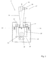
- eine geschnittene Seitenansicht der Vorrichtung mit einer Urnen-Befülleinrichtung,
- Figur 2
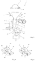
- eine geschnittene Seitenansicht in Einzelansicht der Befülleinrichtung für die Asche,
- Figur 3
- eine geschnittene Seitenansicht des Aufnahmeraumes der Vorrichtung bei geöffneten Wänden,
- Figur 4
- eine perspektivische Darstellung der Weiche in einer ersten Stellung,
- Figur 5
- eine weitere perspektivische Darstellung der Weiche in einer zweiten Stellung,
- Figur 6
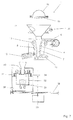
- eine weitere geschnittene Ansicht der Vorrichtung zur Aufbereitung ohne Zyklon, wobei in der
Figur 6 die auf einem Schlitten gelagerte Einfülleinrichtung oder Befülleinrichtung für die Urne angeordnet ist, und - Figur 7
- eine entsprechende geschnittene Ansicht der Vorrichtung gemäß der
Figur 6 , wobei die Befülleinrichtung auf dem Schlitten neben dem Aufnahmeraum verschoben dargestellt ist. - Die
Figur 1 ,3 ,6 und7 zeigen jeweils eine Vorrichtung 1 zur Aufbereitung von in einem Krematorium anfallender Asche 3. Die Vorrichtung 1 verfügt hierbei über eine Einfülleinrichtung 2 für die Asche 3, die in einen Aufnahmeraum 4 zerkleinert wird, nach dem sie aus einem Krematoriumsofen abgezogen wurde. Weiterhin kann die Vorrichtung 1 auch mit einer Befülleinrichtung 5 für die Asche 3 in eine Urne ausgestattet sein. - Der Aufnahmeraum 4, zu erkennen in den
Figuren 1 ,3 ,6 und7 , besteht hierbei aus einem Schacht 6 mit in Wirkung stehenden Wänden 7 und 8, wobei die zur Zerkleinerung der Asche 3 vorgesehenen Wände 7, 8 in Keilform zueinander angeordnet sind, wie dies insbesondere in derFigur 1 gezeigt wird. Aus derFigur 1 in Verbindung mit derFigur 3 ist auch ersichtlich, dass die eine Wand 7 beweglich über ein Exentergetriebe 9 angetrieben wird, wobei die andere zweite Wand 8 gegen die Kraft einer Verstelleinrichtung 10 schwenkbar gelagert ist, wie dies insbesondere aus derFigur 3 ersichtlich ist, wo die Wand 8 zurückgezogen ist. Wie bereits gesagt, ist aus derFigur 1 und3 ersichtlich, dass die bewegliche Wand 7 im oberen Bereich über eine angetriebene Exenterwelle 9 und im unteren Bereich über eine Pendelstütze 11 gelagert ist, so dass infolge des Antriebes 12 eine schwingende Auf- und Abbewegung an der Wand 7 erfolgt. Die zweite Wand 8 ist im oberen Bereich über ein Drehlager 13 und im unteren Bereich durch die Verstelleinrichtung 10 gestützt. Hierbei besteht die Verstelleinrichtung 10 aus einem doppelt wirkenden Kolben 14, der infolge der Ansteuerung in dem Kolbenraum 15 zurück und vor bewegt werden kann, so dass dann die Kolbenstange 16 den unteren Wandbereich der Wand 8 entweder zu der gegenüberliegenden Wand 7 bewegt oder von der Wand 7 wegbewegt wird, wie dies in derFigur 3 dargestellt ist. Aufgrund dieser Ausbildung wird erreicht, dass der Mahlraum entsprechend schmal oder groß gehalten werden kann. Befindet sich zwischen den Wänden 7 und 8 ein sperriger Gegenstand, wie beispielsweise ein Sargbeschlag oder andere metallische Gegenstände, ist der Aufnahmeraum 4 somit in der Lage, diesen sperrigen Gegenständen auszuweichen, in dem die zweite Wand 8 hier im unteren Bereich den Mahlraum öffnet, so dass diese Teile dann herausfallen können. Wie bereits gesagt, umfasst die Verstelleinrichtung 10 einen Hubzylinderkolben mittels der der untere Bereich der zweiten Wand 8 zur Öffnung des Aufnahmeraumes 4 nach unten zurückziehbar ist. - Wie aus den
Figuren 1 ,3 ,6 und7 weiter zu erkennen ist, ist über dem Aufnahmeraum 4 ein Trichter 17 mit der Einfülleinrichtung 2 für die Asche 3 angeordnet. Um die Vorrichtung 1 nun zu befüllen, wird eine Aschewanne 18 zunächst in die Kippeinheit 19 eingeschoben, wobei dann durch Drehung der Kippeinheit 18, gemäß dem dargestellten Pfeil, die Asche 3 aus der Aschewanne 18 in den Trichter 17 fällt, der hier insbesondere um Ablagerungen zu vermeiden mit einem Exentererreger 20 zusammenwirkt, um die Trichterwände in Schwingung zu halten. Die in den Trichter 17 eingefüllte Asche 3 fällt dann in den Schacht 6, wo wie beschrieben sich der Mahlvorgang bzw. der Zerkleinerungsvorgang vollzieht. - Unterhalb des Aufnahmeraumes 4 ist ein Auffangbehältnis 21 für die Aschepartikel vorgesehen, welches als Weiche 22 schwenkbar gelagert ist. In Einzeldarstellung der Weiche 22 wird deutlich, wie die Weiche 22 arbeitet, wobei dies insbesondere in der
Figur 4 und 5 gezeigt wird. So zeigt dieFigur 5 eine erste Stellung der Weiche 22, wobei das aufnehmende Gefäß 23 nach oben gerichtet ist, so dass bei einem normalen Mahlprozess die Asche 3 in dem Gefäß 23 aufgenommen wird. Durch einen Zylinder 24 kann die Weiche 22 in eine zweite Lage gesteuert werden, wie in derFigur 5 dargestellt, wobei dann eine Schräge 25 unter den Aufnahmeraum 4 verschwenkt wird, so dass grobe Teile über die Schräge 25 in ein weiteres Behältnis 26 abgeführt werden kann. In derFigur 3 ist dargestellt, dass die beiden Wände 7 und 8 auf Distanz sind, so dass grobe Teile über die Schrägfläche 25 der Weiche 22 dann in das Behältnis 26 fallen können. - Nach einer besonders vorteilhaften Ausgestaltung der Vorrichtung 1 kann hierbei das Auffangbehältnis 21 über eine Leitung 27, angedeutet in der
Figur 1 , mit einem Zyklonabscheider 28 zur Absaugung der Asche 3 angeschlossen werden, wobei hierzu am tiefsten Punkt des Auffangbehältnisses 21 ein Anschluss 29 vorgesehen ist, auf dem dann ein flexibler Schlauch angeschlossen werden kann, der dann entsprechend an dem Zyklonabscheider 28 tangential angesetzt werden kann. Am oberen Auslass des Zyklonenabscheiders 28 kann an den Stutzen 30 ein Staubsauger oder dergleichen angeschlossen werden, der dann den nötigen Unterdruck erzeugt, um die Asche 3 in den Zyklonenbereich einzusaugen, die dann spiralförmig zum Auslass bzw. zum Produktaustritt 31 am Zyklonabscheider 28 gefördert wird. - Wie insbesondere aus der
Figur 1 zu erkennen ist, ist mit dem Produktaustritt 31 des Zyklonabscheiders 28 eine Urne 32 verbunden, die hier entsprechende dem Öffnungsquerschnitt angepasst an dem Produktaustritt 31 angesetzt ist. Die Urne 32 befindet sich hierbei auf einem sogenannten Rütteltisch 33 der dafür sorgt, dass eine verbesserte Setzung der Asche 3 in der Urne 32 vollzogen wird. Der schwinggelagerte Rütteltisch 33 ist hierbei über Federn 34 gelagert, wobei unterhalb des Urnentisches 35 Gewichte 36 bewegt werden, die die Schwingungen am Rütteltisch 33 bewirken. Die gesamte Mechanik der Befülleinrichtung ist in einer mit einer nicht näher dargestellten Tür dicht verschließbaren Kammer 39 untergebracht. Diese Kammer 39 ist dicht mit dem Zyklonabscheider 28 verbunden. Zwischen dem unteren Austritt 31 des feststehenden Zyklonabscheiders 28 und der mit dem Rütteltisch 33 schwingende Urne 32 ist ein Faltenbalg 40 angeordnet, der Schwingungsbewegung kompensiert und einen Staubaustritt in die Kammer 39 verhindert. Um die Funktion des Faltenbalges sicherzustellen ist zwischen dem Raum in der Urne 32 und der Kammer 39 ein Kanal 37 zum Druckausgleich vorgesehen. - Beim Einschalten der für die pneumatische Förderung verwendeten Abgassaugvorrichtung, hierzu kann beispielsweise ein Staubsauger verwendet werden, wird zunächst auf den vollständigen Druckausgleich zwischen den Räumen innerhalb und außerhalb der Urne 32 gewartet, bevor der Rütteltisch 33 eingeschaltet wird. Dadurch kann sich der Rütteltisch 33 ohne Einwirkung von Kräften, die sich aus einer Druckdifferenz ergeben würden, bewegen. Der zeitliche Verlauf der Druckdifferenz kann für eine Fehlerdiagnose verwendet werden. Aussagen über das korrekte Einstellen der Urne 32, Beschädigung des Faltenbalgs 40, das dichte Verschließen der Kammer 39 usw. sind möglich.
- Die
Figuren 6 und7 zeigen die Vorrichtung 1 nochmals bei gleicher Wirkungsweise ohne die Zwischenschaltung eines Zyklonabscheiders 28, wobei hierbei die Befülleinrichtung 5 auf einem Tisch 38 verfahrbar ausgestaltet ist. Aus der Zusammenschau derFigur 6 und7 wird deutlich, dass, wenn reine Asche 3 aus dem Aufnahmeraum 4 entnommen wird, der Befülltisch 38 unterhalb des Aufnahmeraumes 4 gefahren ist, stellt es sich ein, dass beispielsweise sperrige Gegenstände die nicht in die Urne 32 gelangen sollen, sich zwischen den Wänden 7 und 8 befinden, wird der Befülltisch 38 aus der Abgabeöffnung des Aufnahmeraumes 4 verfahren, so dass dann die sperrigen Teile durchfallen können in das gesondert aufgestellte Behältnis 26. -
- 1
- Vorrichtung
- 2
- Einfülleinrichtung
- 3
- Asche
- 4
- Aufnahmeraum
- 5
- Befülleinrichtung
- 6
- Schacht
- 7
- Wand Exzenter
- 8
- Wand Verstelleinrichtung
- 9
- Exzentergetriebe
- 10
- Verstelleinrichtung
- 11
- Pendelstütze
- 12
- Antrieb
- 13
- Drehlager
- 14
- Kolben
- 15
- Kolbenraum
- 16
- Kolbenstange
- 17
- Trichter
- 18
- Aschewanne
- 19
- Kippeinheit
- 20
- Exzentererreger
- 21
- Auffangbehältnis
- 22
- Weiche
- 23
- Gefäß
- 24
- Zylinder
- 25
- Schräge
- 26
- Behältnis
- 27
- Leitung
- 28
- Zyklonabscheider
- 29
- Anschluss
- 30
- Stutzen
- 31
- Produktaustritt
- 32
- Urne
- 33
- Rütteltisch
- 34
- Feder
- 35
- Urnentisch
- 36
- Gewichte
- 37
- Kanal
- 38
- Tisch
- 39
- Kammer
- 40
- Faltenbalg
Claims (11)
- Vorrichtung (1) zur Aufbereitung von in einem Krematorium anfallender Asche (3),
gekennzeichnet durch
eine Einfülleinrichtung (2) für die Asche (3) in einen Aufnahmeraum (4) zur Zerkleinerung der Aschebestandteile aus einem Krematoriumsofen, sowie einer Befülleinrichtung (5) für die Asche (3), wobei der Aufnahmeraum (4) aus einem Schacht (6) mit in Wirkverbindung stehenden Wänden (7) und (8) besteht, und wobei die zur Zerkleinerung der Asche (3) vorgesehenen Wände (7) und (8) in Keilform zueinander angeordnet sind, wobei die Wand (7) beweglich angetrieben und die andere zweite gegenüberliegende Wand (8) gegen die Kraft einer Verstelleinrichtung (10) schwenkbar gelagert ist. - Vorrichtung nach Anspruch 1,
dadurch gekennzeichnet,
dass die bewegliche Wand (7) im oberen Bereich über eine angetriebene Exenterwelle (9) und im unteren Bereich über eine Pendelstütze (11) gelagert ist. - Vorrichtung nach Anspruch 1 und 2,
dadurch gekennzeichnet,
dass die zweite Wand (8) im oberen Bereich über ein Drehlager (13) und im unteren Bereich durch eine Verstelleinrichtung (10) gestützt ist. - Vorrichtung nach den Ansprüchen 1 bis 3,
dadurch gekennzeichnet,
dass die Verstelleinrichtung (10) einen Hubzylinderkolben (16) umfasst, mittels dem der untere Bereich der zweiten Wand (8) zur Öffnung des Aufnahmeraumes (4) zurückziehbar ist. - Vorrichtung nach den Ansprüchen 1 bis 4,
dadurch gekennzeichnet,
dass über dem Aufnahmeraum (4) ein Trichter (17) mit der Einfülleinrichtung (2) für die Asche (3) angeordnet ist, welche aus einer Kippeinheit (19) für eine Aschewanne (18) besteht. - Vorrichtung nach den Ansprüchen 1 bis 5,
dadurch gekennzeichnet,
dass unterhalb des Aufnahmeraumes (4) ein Auffangbehältnis (21) für die Aschepartikel vorgesehen ist, welches als Weiche (22) schwenkbar gelagert ist. - Vorrichtung nach den Ansprüchen 1 bis 6,
dadurch gekennzeichnet,
dass das Auffangbehältnis (21) an einen Zyklonabscheider (28) zur Absaugung der Asche (3) anschließbar ist. - Vorrichtung nach den Ansprüchen 1 bis 7,
dadurch gekennzeichnet,
dass mit dem Produktaustritt (31) des Zyklonabscheiders (28) eine Urne (32) verbunden ist, die auf einer elastisch gelagerten, in Schwingung versetzbaren Einrichtung (33) gelagert ist. - Vorrichtung nach den Ansprüchen 1 bis 8,
dadurch gekennzeichnet,
dass die Befülleineinrichtung (5) eine die Urne (32) und den Rütteltische (33) umschließende zur Umgebung hin dicht verschließbare Kammer (39) umfasst. - Vorrichtung nach den Ansprüchen 1 bis 9,
dadurch gekennzeichnet,
dass zwischen der Kammer (39) und dem Inneren der Urne (32) ein Kanal (37) zum Druckausgleich vorgesehen ist. - Vorrichtung nach den Ansprüchen 1 bis 10,
dadurch gekennzeichnet,
dass der zeitliche Verlauf des durch den Kanal 37 erfolgten Druckausgleichs zur Auswertung des Betriebszustandes verwendbar ist.
Applications Claiming Priority (1)
| Application Number | Priority Date | Filing Date | Title |
|---|---|---|---|
| DE202015105491.2U DE202015105491U1 (de) | 2015-10-16 | 2015-10-16 | Vorrichtung zur Aufbereitung von in einem Krematorium anfallender Asche |
Publications (2)
| Publication Number | Publication Date |
|---|---|
| EP3163164A1 true EP3163164A1 (de) | 2017-05-03 |
| EP3163164B1 EP3163164B1 (de) | 2018-11-28 |
Family
ID=56958756
Family Applications (1)
| Application Number | Title | Priority Date | Filing Date |
|---|---|---|---|
| EP16188692.4A Active EP3163164B1 (de) | 2015-10-16 | 2016-09-14 | Vorrichtung zur aufbereitung von in einem krematorium anfallender asche |
Country Status (2)
| Country | Link |
|---|---|
| EP (1) | EP3163164B1 (de) |
| DE (1) | DE202015105491U1 (de) |
Citations (3)
| Publication number | Priority date | Publication date | Assignee | Title |
|---|---|---|---|---|
| US1683917A (en) * | 1923-01-10 | 1928-09-11 | Frederick Engineering Company | Apparatus for handling ashes and other materials |
| US3770215A (en) * | 1970-10-21 | 1973-11-06 | Condux Werk | Comminuting device |
| US20130233951A1 (en) * | 2010-11-15 | 2013-09-12 | Europe Metal Concept - Emc | System for treating residues resulting from the combustion of a casket containing the body of a deceased person |
-
2015
- 2015-10-16 DE DE202015105491.2U patent/DE202015105491U1/de not_active Expired - Lifetime
-
2016
- 2016-09-14 EP EP16188692.4A patent/EP3163164B1/de active Active
Patent Citations (3)
| Publication number | Priority date | Publication date | Assignee | Title |
|---|---|---|---|---|
| US1683917A (en) * | 1923-01-10 | 1928-09-11 | Frederick Engineering Company | Apparatus for handling ashes and other materials |
| US3770215A (en) * | 1970-10-21 | 1973-11-06 | Condux Werk | Comminuting device |
| US20130233951A1 (en) * | 2010-11-15 | 2013-09-12 | Europe Metal Concept - Emc | System for treating residues resulting from the combustion of a casket containing the body of a deceased person |
Also Published As
| Publication number | Publication date |
|---|---|
| DE202015105491U1 (de) | 2016-10-19 |
| EP3163164B1 (de) | 2018-11-28 |
Similar Documents
| Publication | Publication Date | Title |
|---|---|---|
| EP0406644B1 (de) | Luftstrom-Wälzmühle | |
| EP0458059A1 (de) | Hammerbrecher | |
| DE102015120112A1 (de) | Hub-/Kippeinrichtung zum Entleeren eines Sammelbehälters in eine Ballenpresse nebst Ballenpresse und Verfahren zum Befüllen der Ballenpresse | |
| EP3634638A1 (de) | Vorrichtung zum auftrennen von konglomeraten, die aus materialien unterschiedlicher dichte bestehen | |
| DE102010030898A1 (de) | Staubsammelsystem für Staubsauger | |
| EP3163164B1 (de) | Vorrichtung zur aufbereitung von in einem krematorium anfallender asche | |
| DE102016110086A1 (de) | Vorrichtung zum Auftrennen von Konglomeraten, die aus Materialien unterschiedlicher Dichte bestehen | |
| DE4329787C2 (de) | Verfahren zum Aufbereiten von Steine enthaltendem, kontaminiertem, bindigem Bodenmaterial und Vorrichtung zur Durchführung des Verfahrens | |
| DE134873C (de) | ||
| DE4120456A1 (de) | Verfahren sowohl zum zerkleinern als auch zum trennen von materialien | |
| DE2051576B2 (de) | Einrichtung zur behandlung von einaescherungsrueckstaenden in krematorien und anschliessendem urnenfuellen | |
| DE1151717B (de) | Hammermuehle zum Zerkleinern inhomogener Stoffe | |
| DE879230C (de) | Vorrichtung zum Be- und Entladen von Schuettgutwagen, insbesondere Muellwagen | |
| DE102011006767A1 (de) | Entsorgungsvorrichtung zur Entsorgung von Speiseresten | |
| DE102019005890A1 (de) | Prallmühle zur Zerkleinerung von Feststoffen | |
| DE499219C (de) | Verbund-Trommelmuehle mit einer Vorzerkleinerungskammer und einer von dieser durch eine Siebwand oder eine UEberfuehrungskammer getrennten Feinmahlkammer von geringerem Durchmesser | |
| EP3832020A1 (de) | Bodenbearbeitungsmaschine mit gefilterter staubabsaugung mit elastisch verformbarem filtergehäuse | |
| DE102018208711A1 (de) | Beschickungsschacht für Stempelkneter | |
| DE1102532B (de) | Schleudermuehle | |
| DE2455916C3 (de) | Schwingmühle, zum Zerkleinern von stückigem Gut, insbesondere von Gestein | |
| DE10338878B4 (de) | Verfahren zum Sammeln der Asche von Einäscherungsvorgängen | |
| DE2428833C3 (de) | Gießerei-Altsand-Aufbereitung | |
| DE102024125134A1 (de) | Mahlwerkseinheit zum Mahlen von Mahlgut, insbesondere zum Mahlen von Kaffeebohnen | |
| DE738285C (de) | Vorrichtung zum Herstellen von Metallpulver und Metallblaettchen | |
| DE245957C (de) |
Legal Events
| Date | Code | Title | Description |
|---|---|---|---|
| PUAI | Public reference made under article 153(3) epc to a published international application that has entered the european phase |
Free format text: ORIGINAL CODE: 0009012 |
|
| STAA | Information on the status of an ep patent application or granted ep patent |
Free format text: STATUS: THE APPLICATION HAS BEEN PUBLISHED |
|
| AK | Designated contracting states |
Kind code of ref document: A1 Designated state(s): AL AT BE BG CH CY CZ DE DK EE ES FI FR GB GR HR HU IE IS IT LI LT LU LV MC MK MT NL NO PL PT RO RS SE SI SK SM TR |
|
| AX | Request for extension of the european patent |
Extension state: BA ME |
|
| STAA | Information on the status of an ep patent application or granted ep patent |
Free format text: STATUS: REQUEST FOR EXAMINATION WAS MADE |
|
| 17P | Request for examination filed |
Effective date: 20171026 |
|
| RBV | Designated contracting states (corrected) |
Designated state(s): AL AT BE BG CH CY CZ DE DK EE ES FI FR GB GR HR HU IE IS IT LI LT LU LV MC MK MT NL NO PL PT RO RS SE SI SK SM TR |
|
| GRAP | Despatch of communication of intention to grant a patent |
Free format text: ORIGINAL CODE: EPIDOSNIGR1 |
|
| STAA | Information on the status of an ep patent application or granted ep patent |
Free format text: STATUS: GRANT OF PATENT IS INTENDED |
|
| RIC1 | Information provided on ipc code assigned before grant |
Ipc: F23J 1/00 20060101ALI20180718BHEP Ipc: F23G 1/00 20060101ALI20180718BHEP Ipc: F23J 1/02 20060101AFI20180718BHEP |
|
| INTG | Intention to grant announced |
Effective date: 20180821 |
|
| GRAS | Grant fee paid |
Free format text: ORIGINAL CODE: EPIDOSNIGR3 |
|
| GRAA | (expected) grant |
Free format text: ORIGINAL CODE: 0009210 |
|
| STAA | Information on the status of an ep patent application or granted ep patent |
Free format text: STATUS: THE PATENT HAS BEEN GRANTED |
|
| AK | Designated contracting states |
Kind code of ref document: B1 Designated state(s): AL AT BE BG CH CY CZ DE DK EE ES FI FR GB GR HR HU IE IS IT LI LT LU LV MC MK MT NL NO PL PT RO RS SE SI SK SM TR |
|
| REG | Reference to a national code |
Ref country code: CH Ref legal event code: EP |
|
| REG | Reference to a national code |
Ref country code: AT Ref legal event code: REF Ref document number: 1070664 Country of ref document: AT Kind code of ref document: T Effective date: 20181215 |
|
| REG | Reference to a national code |
Ref country code: DE Ref legal event code: R096 Ref document number: 502016002623 Country of ref document: DE |
|
| REG | Reference to a national code |
Ref country code: IE Ref legal event code: FG4D Free format text: LANGUAGE OF EP DOCUMENT: GERMAN |
|
| REG | Reference to a national code |
Ref country code: CH Ref legal event code: NV Representative=s name: VALIPAT S.A. GEVERS SA, CH Ref country code: CH Ref legal event code: PCAR Free format text: NEW ADDRESS: RUE DES NOYERS 11, 2000 NEUCHATEL (CH) |
|
| REG | Reference to a national code |
Ref country code: LT Ref legal event code: MG4D Ref country code: NL Ref legal event code: FP |
|
| PG25 | Lapsed in a contracting state [announced via postgrant information from national office to epo] |
Ref country code: LV Free format text: LAPSE BECAUSE OF FAILURE TO SUBMIT A TRANSLATION OF THE DESCRIPTION OR TO PAY THE FEE WITHIN THE PRESCRIBED TIME-LIMIT Effective date: 20181128 Ref country code: ES Free format text: LAPSE BECAUSE OF FAILURE TO SUBMIT A TRANSLATION OF THE DESCRIPTION OR TO PAY THE FEE WITHIN THE PRESCRIBED TIME-LIMIT Effective date: 20181128 Ref country code: NO Free format text: LAPSE BECAUSE OF FAILURE TO SUBMIT A TRANSLATION OF THE DESCRIPTION OR TO PAY THE FEE WITHIN THE PRESCRIBED TIME-LIMIT Effective date: 20190228 Ref country code: FI Free format text: LAPSE BECAUSE OF FAILURE TO SUBMIT A TRANSLATION OF THE DESCRIPTION OR TO PAY THE FEE WITHIN THE PRESCRIBED TIME-LIMIT Effective date: 20181128 Ref country code: IS Free format text: LAPSE BECAUSE OF FAILURE TO SUBMIT A TRANSLATION OF THE DESCRIPTION OR TO PAY THE FEE WITHIN THE PRESCRIBED TIME-LIMIT Effective date: 20190328 Ref country code: LT Free format text: LAPSE BECAUSE OF FAILURE TO SUBMIT A TRANSLATION OF THE DESCRIPTION OR TO PAY THE FEE WITHIN THE PRESCRIBED TIME-LIMIT Effective date: 20181128 Ref country code: BG Free format text: LAPSE BECAUSE OF FAILURE TO SUBMIT A TRANSLATION OF THE DESCRIPTION OR TO PAY THE FEE WITHIN THE PRESCRIBED TIME-LIMIT Effective date: 20190228 Ref country code: HR Free format text: LAPSE BECAUSE OF FAILURE TO SUBMIT A TRANSLATION OF THE DESCRIPTION OR TO PAY THE FEE WITHIN THE PRESCRIBED TIME-LIMIT Effective date: 20181128 |
|
| PG25 | Lapsed in a contracting state [announced via postgrant information from national office to epo] |
Ref country code: RS Free format text: LAPSE BECAUSE OF FAILURE TO SUBMIT A TRANSLATION OF THE DESCRIPTION OR TO PAY THE FEE WITHIN THE PRESCRIBED TIME-LIMIT Effective date: 20181128 Ref country code: SE Free format text: LAPSE BECAUSE OF FAILURE TO SUBMIT A TRANSLATION OF THE DESCRIPTION OR TO PAY THE FEE WITHIN THE PRESCRIBED TIME-LIMIT Effective date: 20181128 Ref country code: PT Free format text: LAPSE BECAUSE OF FAILURE TO SUBMIT A TRANSLATION OF THE DESCRIPTION OR TO PAY THE FEE WITHIN THE PRESCRIBED TIME-LIMIT Effective date: 20190328 Ref country code: AL Free format text: LAPSE BECAUSE OF FAILURE TO SUBMIT A TRANSLATION OF THE DESCRIPTION OR TO PAY THE FEE WITHIN THE PRESCRIBED TIME-LIMIT Effective date: 20181128 Ref country code: GR Free format text: LAPSE BECAUSE OF FAILURE TO SUBMIT A TRANSLATION OF THE DESCRIPTION OR TO PAY THE FEE WITHIN THE PRESCRIBED TIME-LIMIT Effective date: 20190301 |
|
| PG25 | Lapsed in a contracting state [announced via postgrant information from national office to epo] |
Ref country code: DK Free format text: LAPSE BECAUSE OF FAILURE TO SUBMIT A TRANSLATION OF THE DESCRIPTION OR TO PAY THE FEE WITHIN THE PRESCRIBED TIME-LIMIT Effective date: 20181128 Ref country code: PL Free format text: LAPSE BECAUSE OF FAILURE TO SUBMIT A TRANSLATION OF THE DESCRIPTION OR TO PAY THE FEE WITHIN THE PRESCRIBED TIME-LIMIT Effective date: 20181128 Ref country code: CZ Free format text: LAPSE BECAUSE OF FAILURE TO SUBMIT A TRANSLATION OF THE DESCRIPTION OR TO PAY THE FEE WITHIN THE PRESCRIBED TIME-LIMIT Effective date: 20181128 Ref country code: IT Free format text: LAPSE BECAUSE OF FAILURE TO SUBMIT A TRANSLATION OF THE DESCRIPTION OR TO PAY THE FEE WITHIN THE PRESCRIBED TIME-LIMIT Effective date: 20181128 |
|
| REG | Reference to a national code |
Ref country code: DE Ref legal event code: R097 Ref document number: 502016002623 Country of ref document: DE |
|
| PG25 | Lapsed in a contracting state [announced via postgrant information from national office to epo] |
Ref country code: SK Free format text: LAPSE BECAUSE OF FAILURE TO SUBMIT A TRANSLATION OF THE DESCRIPTION OR TO PAY THE FEE WITHIN THE PRESCRIBED TIME-LIMIT Effective date: 20181128 Ref country code: RO Free format text: LAPSE BECAUSE OF FAILURE TO SUBMIT A TRANSLATION OF THE DESCRIPTION OR TO PAY THE FEE WITHIN THE PRESCRIBED TIME-LIMIT Effective date: 20181128 Ref country code: SM Free format text: LAPSE BECAUSE OF FAILURE TO SUBMIT A TRANSLATION OF THE DESCRIPTION OR TO PAY THE FEE WITHIN THE PRESCRIBED TIME-LIMIT Effective date: 20181128 Ref country code: EE Free format text: LAPSE BECAUSE OF FAILURE TO SUBMIT A TRANSLATION OF THE DESCRIPTION OR TO PAY THE FEE WITHIN THE PRESCRIBED TIME-LIMIT Effective date: 20181128 |
|
| PLBE | No opposition filed within time limit |
Free format text: ORIGINAL CODE: 0009261 |
|
| STAA | Information on the status of an ep patent application or granted ep patent |
Free format text: STATUS: NO OPPOSITION FILED WITHIN TIME LIMIT |
|
| PG25 | Lapsed in a contracting state [announced via postgrant information from national office to epo] |
Ref country code: SI Free format text: LAPSE BECAUSE OF FAILURE TO SUBMIT A TRANSLATION OF THE DESCRIPTION OR TO PAY THE FEE WITHIN THE PRESCRIBED TIME-LIMIT Effective date: 20181128 |
|
| 26N | No opposition filed |
Effective date: 20190829 |
|
| PG25 | Lapsed in a contracting state [announced via postgrant information from national office to epo] |
Ref country code: TR Free format text: LAPSE BECAUSE OF FAILURE TO SUBMIT A TRANSLATION OF THE DESCRIPTION OR TO PAY THE FEE WITHIN THE PRESCRIBED TIME-LIMIT Effective date: 20181128 |
|
| PG25 | Lapsed in a contracting state [announced via postgrant information from national office to epo] |
Ref country code: MC Free format text: LAPSE BECAUSE OF FAILURE TO SUBMIT A TRANSLATION OF THE DESCRIPTION OR TO PAY THE FEE WITHIN THE PRESCRIBED TIME-LIMIT Effective date: 20181128 |
|
| PG25 | Lapsed in a contracting state [announced via postgrant information from national office to epo] |
Ref country code: LU Free format text: LAPSE BECAUSE OF NON-PAYMENT OF DUE FEES Effective date: 20190914 Ref country code: IE Free format text: LAPSE BECAUSE OF NON-PAYMENT OF DUE FEES Effective date: 20190914 |
|
| REG | Reference to a national code |
Ref country code: BE Ref legal event code: MM Effective date: 20190930 |
|
| PG25 | Lapsed in a contracting state [announced via postgrant information from national office to epo] |
Ref country code: BE Free format text: LAPSE BECAUSE OF NON-PAYMENT OF DUE FEES Effective date: 20190930 |
|
| PG25 | Lapsed in a contracting state [announced via postgrant information from national office to epo] |
Ref country code: FR Free format text: LAPSE BECAUSE OF NON-PAYMENT OF DUE FEES Effective date: 20190930 |
|
| PG25 | Lapsed in a contracting state [announced via postgrant information from national office to epo] |
Ref country code: CY Free format text: LAPSE BECAUSE OF FAILURE TO SUBMIT A TRANSLATION OF THE DESCRIPTION OR TO PAY THE FEE WITHIN THE PRESCRIBED TIME-LIMIT Effective date: 20181128 |
|
| PG25 | Lapsed in a contracting state [announced via postgrant information from national office to epo] |
Ref country code: HU Free format text: LAPSE BECAUSE OF FAILURE TO SUBMIT A TRANSLATION OF THE DESCRIPTION OR TO PAY THE FEE WITHIN THE PRESCRIBED TIME-LIMIT; INVALID AB INITIO Effective date: 20160914 Ref country code: MT Free format text: LAPSE BECAUSE OF FAILURE TO SUBMIT A TRANSLATION OF THE DESCRIPTION OR TO PAY THE FEE WITHIN THE PRESCRIBED TIME-LIMIT Effective date: 20181128 |
|
| REG | Reference to a national code |
Ref country code: DE Ref legal event code: R082 Ref document number: 502016002623 Country of ref document: DE Representative=s name: BAUER WAGNER PELLENGAHR SROKA PATENT- & RECHTS, DE Ref country code: DE Ref legal event code: R082 Ref document number: 502016002623 Country of ref document: DE Representative=s name: BAUER PSU PARTG MBB, DE |
|
| PG25 | Lapsed in a contracting state [announced via postgrant information from national office to epo] |
Ref country code: MK Free format text: LAPSE BECAUSE OF FAILURE TO SUBMIT A TRANSLATION OF THE DESCRIPTION OR TO PAY THE FEE WITHIN THE PRESCRIBED TIME-LIMIT Effective date: 20181128 |
|
| P01 | Opt-out of the competence of the unified patent court (upc) registered |
Effective date: 20230520 |
|
| REG | Reference to a national code |
Ref country code: CH Ref legal event code: U11 Free format text: ST27 STATUS EVENT CODE: U-0-0-U10-U11 (AS PROVIDED BY THE NATIONAL OFFICE) Effective date: 20251001 |
|
| PGFP | Annual fee paid to national office [announced via postgrant information from national office to epo] |
Ref country code: DE Payment date: 20250930 Year of fee payment: 10 |
|
| PGFP | Annual fee paid to national office [announced via postgrant information from national office to epo] |
Ref country code: NL Payment date: 20250925 Year of fee payment: 10 |
|
| PGFP | Annual fee paid to national office [announced via postgrant information from national office to epo] |
Ref country code: GB Payment date: 20250923 Year of fee payment: 10 |
|
| PGFP | Annual fee paid to national office [announced via postgrant information from national office to epo] |
Ref country code: AT Payment date: 20250917 Year of fee payment: 10 |
|
| PGFP | Annual fee paid to national office [announced via postgrant information from national office to epo] |
Ref country code: CH Payment date: 20251001 Year of fee payment: 10 |