EP3160023B1 - Lotpumpe - Google Patents
Lotpumpe Download PDFInfo
- Publication number
- EP3160023B1 EP3160023B1 EP16180008.1A EP16180008A EP3160023B1 EP 3160023 B1 EP3160023 B1 EP 3160023B1 EP 16180008 A EP16180008 A EP 16180008A EP 3160023 B1 EP3160023 B1 EP 3160023B1
- Authority
- EP
- European Patent Office
- Prior art keywords
- solder
- conveyor channel
- permanent magnet
- solder pot
- pump
- Prior art date
- Legal status (The legal status is an assumption and is not a legal conclusion. Google has not performed a legal analysis and makes no representation as to the accuracy of the status listed.)
- Not-in-force
Links
Images


Classifications
-
- B—PERFORMING OPERATIONS; TRANSPORTING
- B23—MACHINE TOOLS; METAL-WORKING NOT OTHERWISE PROVIDED FOR
- B23K—SOLDERING OR UNSOLDERING; WELDING; CLADDING OR PLATING BY SOLDERING OR WELDING; CUTTING BY APPLYING HEAT LOCALLY, e.g. FLAME CUTTING; WORKING BY LASER BEAM
- B23K3/00—Tools, devices or special appurtenances for soldering, e.g. brazing, or unsoldering, not specially adapted for particular methods
- B23K3/06—Solder feeding devices; Solder melting pans
- B23K3/0646—Solder baths
- B23K3/0653—Solder baths with wave generating means, e.g. nozzles, jets, fountains
-
- B—PERFORMING OPERATIONS; TRANSPORTING
- B23—MACHINE TOOLS; METAL-WORKING NOT OTHERWISE PROVIDED FOR
- B23K—SOLDERING OR UNSOLDERING; WELDING; CLADDING OR PLATING BY SOLDERING OR WELDING; CUTTING BY APPLYING HEAT LOCALLY, e.g. FLAME CUTTING; WORKING BY LASER BEAM
- B23K3/00—Tools, devices or special appurtenances for soldering, e.g. brazing, or unsoldering, not specially adapted for particular methods
- B23K3/06—Solder feeding devices; Solder melting pans
- B23K3/0607—Solder feeding devices
- B23K3/0638—Solder feeding devices for viscous material feeding, e.g. solder paste feeding
-
- H—ELECTRICITY
- H02—GENERATION; CONVERSION OR DISTRIBUTION OF ELECTRIC POWER
- H02K—DYNAMO-ELECTRIC MACHINES
- H02K44/00—Machines in which the dynamo-electric interaction between a plasma or flow of conductive liquid or of fluid-borne conductive or magnetic particles and a coil system or magnetic field converts energy of mass flow into electrical energy or vice versa
- H02K44/02—Electrodynamic pumps
-
- H—ELECTRICITY
- H02—GENERATION; CONVERSION OR DISTRIBUTION OF ELECTRIC POWER
- H02K—DYNAMO-ELECTRIC MACHINES
- H02K44/00—Machines in which the dynamo-electric interaction between a plasma or flow of conductive liquid or of fluid-borne conductive or magnetic particles and a coil system or magnetic field converts energy of mass flow into electrical energy or vice versa
- H02K44/02—Electrodynamic pumps
- H02K44/06—Induction pumps
Definitions
- the invention relates to a solder pot, in particular a Selektivlöttiegel for a soldering system for selective wave soldering, comprising a solder pump for conveying an electrically conductive fluid, in particular a liquid solder, with an at least partially along a circular path extending conveyor channel with an inlet and an outlet and with a device for generating a moving magnetic field.
- solder pumps are already known from the prior art.
- the device for generating the moving magnetic field comprises at least one electromagnet.
- the CN 101 382 153 B , the US 2009/285695 A1 , the JP H05 161340 A and the CN 202 334 245 U show features of the preamble of claim 1.
- the invention is therefore based on the object to provide a solder pump, which avoids the disadvantages mentioned, and in particular to provide a solder pump, which has a reduced size and improved efficiency.
- solder pot is particularly advantageous because due to the smaller size of the solder pump, the solder pot takes up a smaller overall space and thus can be arranged in a system for selective wave soldering several solder pot space saving on an axis.
- the conveying channel is limited on its side facing away from the permanent magnet of a ferromagnetic material. Consequently, it can be provided that the conveying channel is formed from a groove and a cover covering the groove made of ferromagnetic material. It is further provided that the delivery channel is limited on its side facing the permanent magnet of a non-ferromagnetic material. Advantageously, it can be provided that the delivery channel is introduced into the non-ferromagnetic material in the manner of a groove or annular groove.
- the moving magnetic field eddy currents can be generated during operation of the solder pump in an electrically conductive fluid, in particular in a liquid solder.
- the electrically conductive fluid or the liquid solder can be accelerated in the direction of movement along the at least partially along a circular path extending conveyor channel and thus a pumping action of the solder pump can be provided.
- the arrangement of a magnetic or ferromagnetic material on the side facing away from the permanent magnet side of the conveying channel, the formation of a magnetic field in the conveying channel can be improved.
- a rotating magnetic field can be generated in the conveying channel, which extends at least in sections along a circular path, that forms between the magnetic or ferromagnetic material and the permanent magnet.
- the delivery channel extends between an inlet and an outlet along the circular path at a circumferential angle in the range of 140 to 350 °, more preferably in a circumferential angle in the range of 160 ° to 350 °.
- An advantageous development of the invention provides that at least two permanent magnets are provided, which are arranged such that the permanent magnets facing the conveyor channel with a mutually different magnetic pole.
- the permanent magnets are arranged on a magnetic circuit track.
- the magnetic circuit is arranged concentrically to the circular path of the conveyor channel.
- the conveying channel is limited by a ferromagnetic material that is formed as a half-cylindrical sleeve.
- the delivery channel is bounded on the one hand by a convex outer side of a hollow half-cylinder and on the other hand by a concave inner side of a semi-cylindrical sleeve of ferromagnetic material.
- the delivery channel is completely inserted in non-ferromagnetic material and is completely bounded by the non-ferromagnetic material except for an inlet and an outlet.
- the at least one permanent magnet is arranged axially below the conveying channel. It is particularly preferred if the at least one permanent magnet or the plurality of permanent magnets are arranged on a disc which is rotatably drivable for rotation about the axis of rotation and is arranged perpendicular to the axis of rotation.
- the at least one permanent magnet is arranged radially inward next to the conveying channel.
- the radial direction is a direction perpendicular to the axis of rotation, wherein an axial direction of a direction is parallel to the axis of rotation.
- the at least one permanent magnet is arranged radially outside next to the conveyor channel.
- an electric motor is provided, wherein the at least one permanent magnet for rotation about the axis of rotation of the electric motor can be driven.
- the inlet and the outlet are arranged at opposite ends of the conveyor channel.
- FIG. 1 shows a first embodiment of a soldering pump 10 of a solder pot according to the invention in a side view in section.
- the solder pump 10 is designed for conveying an electrically conductive fluid, in particular for conveying a liquid solder.
- Such a soldering pump 10 can for example be installed in a solder pot of a system for selective wave soldering for conveying the liquid solder. However, such a solder pot is not shown in the figures.
- the solder pump 10 has an at least partially along a circular path 12 extending conveyor channel 14 with an inlet 16 and an outlet 18.
- the delivery channel 14 of the soldering pump 10 is in FIG. 2 shown in a plan view.
- the inlet 16, the outlet 18 and the circular path 12 are clearly visible.
- the inlet and the outlet 18 are arranged at the opposite ends of the conveying channel 14.
- the solder pump 10 also has a device 20 for generating a rotating magnetic field.
- This device 20 comprises at least one permanent magnet 22.
- the soldering pump 10 or the device 20 comprises a plurality of permanent magnets 22, the conveyor channel 14th alternately facing with a mutually different magnetic pole.
- Such an arrangement of a plurality of permanent magnets 22 is in the plan view according to FIG. 3 clearly visible.
- the permanent magnets 22 are arranged on a magnetic circular path 23 which is arranged concentrically to the circular path 12 of the conveying channel 14.
- the alternately arranged permanent magnets 22 can be clearly seen, wherein in each case a permanent magnet 22 with a south pole 26 upwards, ie the delivery channel 14 is arranged facing and the adjacent arranged permanent magnet with a north pole 24 upwards that is arranged.
- the permanent magnets 22 are in FIG. 3 mounted on a magnetic disk 28, which is also clearly in FIG. 1 can be seen.
- the delivery channel 14 is, as in FIG. 1 can be seen limited by a non-ferromagnetic material 30, in which a groove 32 is introduced. This groove 32 is closed by a ring 34 of ferromagnetic material, wherein the delivery channel 14 is limited in total by the non-ferromagnetic material 30 and the ring 34.
- the device 20 for generating a moving magnetic field is designed such that the permanent magnets 22 rotate in operation about a concentric with the circular path 12 or magnetic circular path 23 arranged rotational axis 35.
- permanent magnets 22 By rotating the axially arranged (parallel to the direction of the rotation axis 35) below the conveying channel 14 permanent magnets 22 can be generated in the conveying channel 14, a rotating magnetic field that forms between the magnetic or ferromagnetic material 34 and the permanent magnet 22.
- eddy currents are generated.
- the electrically conductive fluid or the liquid solder along a by the arrow 36 in FIG. 1 or by the arrows 38 in FIG FIG. 2 shown rotational direction along the at least partially along the circular path 12 extending conveyor channel 14 are accelerated and thus a pumping action of the soldering pump 10 can be provided.
- the soldering pump 10 has an electric motor, not shown in the figures, which drives the magnetic disk 28 or the permanent magnets 22 in such a way that they rotate about the rotational axis 35.
- FIG. 4 shows a second embodiment of a solder pump according to the invention 100 in a side view in section, wherein FIG. 5 a longitudinal section through the solder pump 100 according to FIG. 4 shows.
- the the FIGS. 1 to 3 corresponding elements and components are identified by the corresponding reference numerals.
- a plurality of permanent magnets 22 is provided which can be driven by a shaft 40, which in turn is driven by an electric motor, not shown, for rotation about the rotation axis 35 in the direction of the arrow 36.
- the permanent magnets 22 are arranged concentrically to the rotation axis 35, wherein in each case a permanent magnet 22 with a south pole 26 radially outward (perpendicular to the axis of rotation 35) and the adjacent permanent magnet 22 is arranged with a north pole 24 radially outward (perpendicular to the axis of rotation 35) ,
- the delivery channel 14 is limited in the solder pump 100 by a ferromagnetic material 34, which as semi-cylindrical sleeve 42 is formed.
- the delivery channel 14 is further bounded by a convex hollow half cylinder 44, so that the delivery channel 14 between a concave inner side 46 of the sleeve 42 and a convex outer side 48 of the half cylinder 44 is formed.
- the embodiment of the solder pump 100 according to the FIGS. 4 and 5 corresponds largely to the embodiment of the soldering pump 10 according to the FIGS. 1 to 3 , However, the soldering pump 100 is due to a large width 50 of the conveying channel 14, which in FIG. 5 can be clearly seen, particularly suitable for large volume flows of an electrically conductive fluid or a liquid solder.
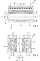
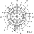
- FIG. 6 shows a solder pump 200 (not the subject of the invention) in a side view in section, wherein FIG. 7 the soldering pump 200 according to FIG. 6 in a plan view in section shows.
- FIGS. 1 to 5 corresponding elements and components are identified by the corresponding reference numerals.
- the solder pump 200 also has a plurality of permanent magnets 22, which are arranged on a magnetic disk 28.
- the soldering pump 200 also has an electric motor, not shown in the figures, which drives the magnetic disk 28 or the permanent magnets 22 in such a way that they rotate about the axis of rotation 35.
- the permanent magnets 22 are arranged both radially inward (perpendicular to the axis of rotation 35) next to the conveying channel 14 and also radially outside (perpendicular to the axis of rotation 35) next to the conveying channel.
- the delivery channel 14 is completely bounded by a non-ferromagnetic material 30 except for the inlet 16 and the outlet 18.
- the permanent magnets 22 are arranged both radially inwardly and radially outwardly such that they alternate with a south pole 26 or a north pole 24 facing the conveyor channel 14. As in FIG.
- the radially inwardly disposed permanent magnets 22 are arranged opposite to the radially outer permanent magnet 22, that on both sides of the conveying channel 14 each have a north pole 24 and a south pole 26 of the opposing permanent magnets 22 are opposite.
- a rotating magnetic field can be generated in the conveying channel 14, which forms between the respective north and south poles 24, 26 of the permanent magnets 22. Since the magnetic flux is generated in each case between the north and south poles 24, 26, a total of a solder pump 200 can be provided with a particularly large conveying effect.
Landscapes
- Engineering & Computer Science (AREA)
- Power Engineering (AREA)
- Mechanical Engineering (AREA)
- Structures Of Non-Positive Displacement Pumps (AREA)
Description
- Die Erfindung betrifft einen Löttiegel, insbesondere einen Selektivlöttiegel für eine Lötanlage zum selektiven Wellenlöten, umfassend eine Lotpumpe zum Fördern eines elektrisch leitfähigen Fluides, insbesondere eines flüssigen Lots, mit einem zumindest abschnittsweise entlang einer Kreisbahn verlaufenden Förderkanal mit einem Einlass und einem Auslass und mit einer Einrichtung zur Erzeugung eines bewegten Magnetfelds. Aus dem Stand der Technik sind derartige Lotpumpen bereits bekannt. Dabei umfasst die Einrichtung zur Erzeugung des bewegten Magnetfeldes wenigstens einen Elektromagneten.
- Die Verwendung von Elektromagneten hat sich jedoch als nachteilig erwiesen, da die Lotpumpen einen vergleichsweise großen Bauraum einnehmen und da der Wirkungsgrad derartiger Lotpumpen, deren Einrichtung zur Erzeugung des bewegten Magnetfelds Elektromagneten aufweist, aufgrund der elektrischen Verluste aufgrund der Bestromung für die Elektromagneten bzw. für die elektrischen Spulen vergleichsweise schlecht ist. Die
CN 101 382 153 B , dieUS 2009/285695 A1 , dieJP H05 161340 A CN 202 334 245 U zeigen Merkmale des Oberbegriffs des Anspruchs 1. - Der Erfindung liegt daher die Aufgabe zugrunde, eine Lotpumpe bereitzustellen, welche die genannte Nachteile vermeidet, und insbesondere eine Lotpumpe bereitzustellen, die eine verringerte Baugröße und einen verbesserten Wirkungsgrad aufweist.
- Diese Aufgabe wird mit einem Löttiegel mit den Merkmalen des Anspruchs 1 gelöst.
- Ein derartiger Löttiegel ist besonders vorteilhaft, da aufgrund der geringeren Baugröße der Lotpumpe der Löttiegel insgesamt einen kleineren Bauraum einnimmt und somit in einer Anlage zum selektiven Wellenlöten mehrere Löttiegel platzsparend auf einer Achse angeordnet werden können.
- Nach Anspruch 1 ist vorgesehen, dass der Förderkanal auf seiner dem Permanentmagneten abgewandten Seite von einem ferromagnetischen Material begrenzt wird. Folglich kann vorgesehen sein, dass der Förderkanal aus einer Nut und einem die Nut abdeckenden Deckel aus ferromagnetischem Material gebildet wird. Ferner ist vorgesehen, dass der Förderkanal auf seiner dem Permanentmagneten zugewandten Seite von einem nicht ferromagnetischen Material begrenzt wird. Vorteilhafterweise kann dabei vorgesehen sein, dass der Förderkanal in das nicht ferromagnetische Material in Art einer Nut oder Ringnut eingebracht ist.
- Aufgrund der Verwendung von Permanentmagneten zur Erzeugung des bewegten Magnetfelds kann eine Reduzierung der Baugröße sowie eine erhebliche Energieeinsparung erreicht werden, da einerseits der Wirkungsgrad der Pumpe aufgrund des Verzichts auf Elektromagneten erhöht werden kann und andererseits der Energieverbrauch einer Anlage zum bspw. selektiven Wellenlöten aufgrund der geringeren zu bewegenden Masse verringert werden kann.
- Durch das bewegte Magnetfeld können im Betrieb der Lotpumpe in einem elektrisch leitfähigen Fluid insbesondere in einem flüssigen Lot, Wirbelströme erzeugt werden. Durch Erzeugung der Wirbelströme kann das elektrisch leitfähige Fluid bzw. das flüssige Lot in Bewegungsrichtung entlang des zumindest abschnittsweise entlang einer Kreisbahn verlaufenden Förderkanals beschleunigt werden und somit kann eine Pumpenwirkung der Lotpumpe bereitgestellt werden.
- Durch die Anordnung eines magnetischen oder ferromagnetischen Materials auf der dem Permanentmagneten abgewandten Seite des Förderkanals kann die Ausbildung eines Magnetfelds im Förderkanal verbessert werden.
- Durch Rotation des Permanentmagneten kann im Förderkanal, der zumindest abschnittsweise entlang einer Kreisbahn verläuft, ein rotierendes Magnetfeld erzeugt werden, dass sich zwischen dem magnetischen oder ferromagnetischen Material und dem Permanentmagneten ausbildet. Vorzugsweise verläuft der Förderkanal zwischen einem Einlass und einem Auslass entlang der Kreisbahn in einem Umfangswinkel im Bereich von 140 bis 350°, weiter vorzugsweise in einem Umfangswinkel im Bereich von 160° bis 350°.
- Eine vorteilhafte Weiterbildung der Erfindung sieht vor, dass wenigstens zwei Permanentmagneten vorgesehen sind, die derart angeordnet sind, dass die Permanentmagneten dem Förderkanal mit einem voneinander verschiedenen Magnetpol zugewandt sind.
- Besonders bevorzugt ist es dabei, wenn eine Vielzahl von Permanentmagneten vorgesehen ist, die dem Förderkanal alternierend mit einem voneinander verschiedenen Magnetpol zugewandt sind.
- Um zu ermöglichen, dass die Permanentmagneten in einfacher Weise im Betrieb um die Rotationsachse rotieren können kann vorteilhafterweise vorgesehen sein, dass die Permanentmagneten auf einer Magnetkreisbahn angeordnet sind.
- Besonders vorteilhaft ist es dabei, wenn die Magnetkreisbahn konzentrisch zur Kreisbahn des Förderkanals angeordnet ist.
- In einer besonders leistungsfähigen Ausgestaltung des Löttiegels für große Volumenströme ist vorgesehen, dass der der Förderkanal von einem ferromagnetischen Material begrenzt wird, dass als halbezylindrische Hülse ausgebildet ist. Vorteilhafterweise wird der Förderkanal dabei einerseits von einer konvexen Außenseite eines hohlen Halbzylinders und andererseits von einer konkaven Innenseite einer halbzylindrischen Hülse aus ferromagnetischem Material begrenzt.
- In einem nicht zur Erfindung gehörenden Gegenstand ist denkbar, dass der Förderkanal vollständig in nicht ferromagnetisches Material eingebracht ist und von dem nicht ferromagnetischen Material bis auf einen Einlass und einen Auslass vollständig begrenzt wird. In einer besonders einfachen Ausgestaltung des Löttiegels ist vorgesehen, dass der wenigstens eine Permanentmagnet axial unterhalb des Förderkanals angeordnet ist. Besonders bevorzugt ist es dabei, wenn der wenigstens eine Permanentmagnet oder die Vielzahl von Permanentmagneten auf einer Scheibe angeordnet sind, die zur Rotation um die Rotationsachse drehantreibbar ist und senkrecht zur Rotationsachse angeordnet ist.
- In einer Weiterbildung des Löttiegels kann vorgesehen sein, dass der wenigstens eine Permanentmagnet radial innen neben dem Förderkanal angeordnet ist. Die radiale Richtung ist dabei eine Richtung senkrecht zur Rotationsachse, wobei eine axiale Richtung einer Richtung parallel zur Rotationsachse ist.
- Es ist jedoch auch denkbar, dass der wenigstens eine Permanentmagnet radial außen neben dem Förderkanal angeordnet ist.
- In einer vorteilhaften Weiterbildung des Löttiegels ist ein Elektromotor vorgesehen, wobei der wenigstens eine Permanentmagnet zur Rotation um die Rotationsachse von dem Elektromotor antreibbar ist.
- Um eine möglichst gute Pumpenwirkung zu erzeugen und um das elektrisch leitfähige Fluid bzw. das flüssige Lot durch die erzeugten Wirbelströme möglichst gut beschleunigen zu können, ist es besonders vorteilhaft, wenn der Einlass und der Auslass an einander abgewandten Enden des Förderkanals angeordnet sind.
- Weitere Einzelheiten und vorteilhafte Ausgestaltungen der Erfindung sind der nachfolgenden Beschreibung zu entnehmen, anhand derer die in den Figuren dargestellten Ausführungsformen der Erfindung näher beschrieben und erläutert sind.
- Es zeigen:
- Figur 1
- eine erste Ausführungsform einer Lotpumpe eines erfindungsgemäßen Löttiegels in einer Seitenansicht im Schnitt;
- Figur 2
- einen Förderkanal der Lotpumpe gemäß
Figur 1 in einer Draufsicht; - Figur 3
- eine Vielzahl auf einer Scheibe angeordneter Permanentmagnete der Lotpumpe gemäß
Figur 1 ; - Figur 4
- eine zweite Ausführungsform einer Lotpumpe eines erfindungsgemäßen Löttiegels in einer Seitenansicht im Schnitt;
- Figur 5
- einen Längsschnitt durch die Lotpumpe gemäß
Figur 4 ; - Figur 6
- eine Lotpumpe (nicht Gegenstand der Erfindung) eines Löttiegels in einer Seitenansicht im Schnitt; und
- Figur 7
- die Lotpumpe gemäß
Figur 6 in einer Draufsicht im Schnitt. -
Figur 1 zeigt eine erste Ausführungsform einer Lotpumpe 10 eines erfindungsgemäßen Löttiegels in einer Seitenansicht im Schnitt. Die Lotpumpe 10 ist zum Fördern eines elektrisch leitfähigen Fluides, insbesondere zum Fördern eines flüssigen Lots ausgelegt. Eine derartige Lotpumpe 10 kann beispielsweise in einen Löttiegel einer Anlage zum selektiven Wellenlöten zum Fördern des flüssigen Lots eingebaut werden. Ein derartiger Löttiegel ist jedoch in den Figuren nicht dargestellt. - Die Lotpumpe 10 weist einen zumindest abschnittsweise entlang einer Kreisbahn 12 verlaufenden Förderkanal 14 mit einem Einlass 16 und einem Auslass 18 auf. Der Förderkanal 14 der Lotpumpe 10 ist in
Figur 2 in einer Draufsicht gezeigt. Der Einlass 16, der Auslass 18 sowie die Kreisbahn 12 sind dabei deutlich zu erkennen. Der Einlass und der Auslass 18 sind an den einander abgewandten Enden des Förderkanals 14 angeordnet. - Die Lotpumpe 10 weist ferner eine Einrichtung 20 zur Erzeugung eines rotierenden Magnetfelds auf. Diese Einrichtung 20 umfasst wenigstens einen Permanentmagneten 22. In der Ausführungsform gemäß der
Figuren 1 bis 3 umfasst die Lotpumpe 10 bzw. die Einrichtung 20 eine Vielzahl von Permanentmagneten 22, die dem Förderkanal 14 alternierend mit einem voneinander verschiedenen Magnetpol zugewandt sind. - Eine derartige Anordnung einer Vielzahl von Permanentmagneten 22 ist in der Draufsicht gemäß
Figur 3 deutlich zu erkennen. Die Permanentmagnete 22 sind dabei auf einer Magnetkreisbahn 23 angeordnet, die konzentrisch zur Kreisbahn 12 des Förderkanals 14 angeordnet ist. Die alternierend angeordneten Permanentmagnete 22 sind dabei deutlich zu erkennen, wobei jeweils ein Permanentmagnet 22 mit einem Südpol 26 nach oben, d.h. dem Förderkanal 14 zugewandt angeordnet ist und der daneben angeordnete Permanentmagnet mit einem Nordpol 24 nach oben d.h. angeordnet ist. Die Permanentmagnete 22 sind inFigur 3 auf einer Magnetscheibe 28 montiert, die ebenfalls deutlich inFigur 1 zu erkennen ist. - Der Förderkanal 14 wird, wie in
Figur 1 zu erkennen ist, von einem nicht ferromagnetischen Material 30 begrenzt, in das eine Nut 32 eingebracht ist. Diese Nut 32 wird von einem Ring 34 aus ferromagnetischem Material verschlossen, wobei der Förderkanal 14 insgesamt von dem nicht ferromagnetischen Material 30 und dem Ring 34 begrenzt wird. - Die Einrichtung 20 zur Erzeugung eines bewegten Magnetfeldes ist derart ausgelegt, dass die Permanentmagnete 22 im Betrieb um eine konzentrisch zur Kreisbahn 12 oder Magnetkreisbahn 23 angeordnete Rotationsachse 35 rotieren. Durch Rotation der axial (parallel zur Richtung der Rotationsachse 35) unterhalb des Förderkanals 14 angeordneten Permanentmagnete 22 kann im Förderkanal 14 ein rotierendes Magnetfeld erzeugt werden, dass sich zwischen dem magnetischen oder ferromagnetischen Material 34 und den Permanentmagneten 22 ausbildet. Durch das rotierende Magnetfeld können im Betrieb der Lotpumpe 10 in einem elektrisch leitfähigen Fluid insbesondere in einem flüssigen Lot, Wirbelströme erzeugt werden. Durch Erzeugung der Wirbelströme kann das elektrisch leitfähige Fluid bzw. das flüssige Lot entlang einer durch den Pfeil 36 in
Figur 1 oder durch die Pfeile 38 inFigur 2 dargestellten Rotationsrichtung entlang des zumindest abschnittsweise entlang der Kreisbahn 12 verlaufenden Förderkanals 14 beschleunigt werden und somit kann eine Pumpenwirkung der Lotpumpe 10 bereitgestellt werden. - Zum Antrieb der Magnetscheibe 28 weist die Lotpumpe 10 einen in den Figuren nicht dargestellten Elektromotor auf, welcher die Magnetscheibe 28 bzw. die Permanentmagnete 22 derart antreibt, dass diese um die Rotationsachse 35 rotieren.
-
Figur 4 zeigt eine zweite Ausführungsform einer erfindungsgemäßen Lotpumpe 100 in einer Seitenansicht im Schnitt, wobeiFigur 5 einen Längsschnitt durch die Lotpumpe 100 gemäßFigur 4 zeigt. Die denFiguren 1 bis 3 entsprechenden Elemente und Bauteile sind dabei mit den entsprechenden Bezugszeichen gekennzeichnet. - Bei der zweiten Ausführungsform der Lotpumpe 100 ist eine Vielzahl von Permanentmagneten 22 vorgesehen, die von einer Welle 40, welche wiederum von einem nicht dargestellten Elektromotor antreibbar ist, zur Rotation um die Rotationsachse 35 in Richtung des Pfeils 36 antreibbar sind. Die Permanentmagneten 22 sind dabei konzentrisch zur Rotationsachse 35 angeordnet, wobei jeweils ein Permanentmagnet 22 mit einem Südpol 26 nach radial außen (senkrecht zur Rotationsachse 35) und der daneben angeordnete Permanentmagnet 22 mit einem Nordpol 24 nach radial außen (senkrecht zur Rotationsachse 35) angeordnet ist.
- Der Förderkanal 14 wird bei der Lotpumpe 100 von einem ferromagnetischen Material 34 begrenzt, das als halbzylindrische Hülse 42 ausgebildet ist. Der Förderkanal 14 wird ferner von einem konvexen hohlen Halbzylinder 44 begrenzt, so dass sich der Förderkanal 14 zwischen einer konkaven Innenseite 46 der Hülse 42 und einer konvexen Außenseite 48 des Halbzylinders 44 ausbildet. Die Ausgestaltung der Lotpumpe 100 gemäß den
Figuren 4 und5 entspricht weitgehend der Ausgestaltung der Lotpumpe 10 gemäß denFiguren 1 bis 3 . Die Lotpumpe 100 ist jedoch aufgrund einer großen Breite 50 des Förderkanals 14, welche inFigur 5 deutlich zu erkennen ist, für große Volumenströme eines elektrisch leitfähigen Fluides bzw. eines flüssigen Lots besonders geeignet. -
Figur 6 zeigt eine Lotpumpe 200 (nicht Gegenstand der Erfindung) in einer Seitenansicht im Schnitt, wobeiFigur 7 die Lotpumpe 200 gemäßFigur 6 in einer Draufsicht im Schnitt zeigt. Die denFiguren 1 bis 5 entsprechenden Elemente und Bauteile sind dabei mit den entsprechenden Bezugszeichen gekennzeichnet. - Die Lotpumpe 200 weist ebenfalls eine Vielzahl von Permanentmagneten 22 auf, die auf einer Magnetscheibe 28 angeordnet sind. Zum Antrieb der Magnetscheibe 28 weist die Lotpumpe 200 auch einen in den Figuren nicht dargestellten Elektromotor auf, welcher die Magnetscheibe 28 bzw. die Permanentmagnete 22 derart antreibt, dass diese um die Rotationsachse 35 rotieren.
- Im Gegensatz zur Lotpumpe 10 der
Figuren 1 bis 3 sind die Permanentmagnete 22 sowohl radial innen (senkrecht zur Rotationsachse 35) neben dem Förderkanal 14 angeordnet als auch radial außen (senkrecht zur Rotationsachse 35) neben dem Förderkanal angeordnet. Der Förderkanal 14 wird bis auf den Einlass 16 und den Auslass 18 vollständig von einem nicht ferromagnetischen Material 30 begrenzt. Die Permanentmagnete 22 sind sowohl radial innen als auch radial außen derart angeordnet, dass sie alternierend mit einem Südpol 26 oder einem Nordpol 24 dem Förderkanal 14 zugewandt sind. Wie inFigur 6 deutlich zu erkennen ist, sind die radial innen angeordneten Permanentmagnete 22 derart gegenüber den radial außen angeordneten Permanentmagneten 22 angeordnet, dass sich auf beiden Seiten des Förderkanals 14 jeweils ein Nordpol 24 und ein Südpol 26 der gegenüberliegenden Permanentmagnete 22 gegenüberliegen. - Durch Rotation der Magnetscheibe 28 bzw. der Permanentmagnete 22 kann im Förderkanal 14 ein rotierendes Magnetfeld erzeugt werden, das sich zwischen den jeweiligen Nord- und Südpolen 24, 26 der Permanentmagnete 22 ausbildet. Da der magnetische Fluss jeweils zwischen den Nord- und Südpolen 24, 26 erzeugt wird, kann insgesamt eine Lotpumpe 200 mit einer besonders großen Förderwirkung bereitgestellt werden.
Claims (8)
- Löttiegel, insbesondere Selektivlöttiegel für eine Lötanlage zum selektiven Wellenlöten,
umfassend eine Lotpumpe (10, 100) zum Fördern eines elektrisch leitfähigen Fluides, insbesondere eines flüssigen Lots, die mit einem zumindest abschnittsweise entlang einer Kreisbahn (12) verlaufenden Förderkanal (14) mit einem Einlass (16) und einem Auslass (18) und mit einer Einrichtung (20) zur Erzeugung eines bewegten Magnetfelds ausgestattet ist, wobei die Einrichtung (20) wenigstens einen Permanentmagneten (22) umfasst und derart ausgelegt ist, dass der Permanentmagnet (22) im Betrieb entlang des Förderkanals (14) bewegt wird, und im Betrieb um eine konzentrisch zur Kreisbahn (12) angeordnete Rotationsachse (35) rotiert,
dadurch gekennzeichnet,
dass der Förderkanal (14) auf seiner dem Permanentmagneten (22) abgewandten Seite von einem ferromagnetischen Material (34) begrenzt wird und dass der Förderkanal (14) auf seiner dem Permanentmagneten zugewandten Seite von einem nicht ferromagnetischen Material (30) begrenzt wird. - Löttiegel nach Anspruch 1, dadurch gekennzeichnet, dass die Einrichtung (20) wenigstens zwei Permanentmagneten (22) aufweist, die derart angeordnet sind, dass die Permanentmagneten (22) dem Förderkanal (14) mit einem voneinander verschiedenen Magnetpol (24, 26) zugewandt sind.
- Löttiegel nach Anspruch 1 oder 2, dadurch gekennzeichnet, dass die Einrichtung (20) eine Vielzahl von Permanentmagneten (22) aufweist, die dem Förderkanal (14) alternierend mit einem voneinander verschiedenen Magnetpol (24, 26) zugewandt sind.
- Löttiegel nach Anspruch 2 oder 3, dadurch gekennzeichnet, dass die Permanentmagneten (22) auf einer Magnetkreisbahn (23) angeordnet sind.
- Löttiegel nach Anspruch 4, dadurch gekennzeichnet, dass die Magnetkreisbahn (23) konzentrisch zur Kreisbahn (12) des Förderkanals (14) angeordnet ist.
- Löttiegel nach wenigstens einem der vorhergehenden Ansprüche, dadurch gekennzeichnet, dass der wenigstens eine Permanentmagnet (22) axial unterhalb des Förderkanals (14) angeordnet ist.
- Löttiegel nach wenigstens einem der vorhergehenden Ansprüche, dadurch gekennzeichnet, dass ein Elektromotor vorgesehen ist, wobei der wenigstens eine Permanentmagnet (22) zur Rotation um die Rotationsachse (35) von dem Elektromotor antreibbar ist.
- Löttiegel nach wenigstens einem der vorhergehenden Ansprüche, dadurch gekennzeichnet, dass der Einlass (16) und der Auslass (18) an einander abgewandten Enden des Förderkanals (14) angeordnet sind.
Priority Applications (1)
| Application Number | Priority Date | Filing Date | Title |
|---|---|---|---|
| PL16180008T PL3160023T3 (pl) | 2015-10-21 | 2016-07-18 | Pompa lutownicza |
Applications Claiming Priority (1)
| Application Number | Priority Date | Filing Date | Title |
|---|---|---|---|
| DE102015220514.2A DE102015220514A1 (de) | 2015-10-21 | 2015-10-21 | Lotpumpe |
Publications (2)
| Publication Number | Publication Date |
|---|---|
| EP3160023A1 EP3160023A1 (de) | 2017-04-26 |
| EP3160023B1 true EP3160023B1 (de) | 2019-10-09 |
Family
ID=56497589
Family Applications (1)
| Application Number | Title | Priority Date | Filing Date |
|---|---|---|---|
| EP16180008.1A Not-in-force EP3160023B1 (de) | 2015-10-21 | 2016-07-18 | Lotpumpe |
Country Status (6)
| Country | Link |
|---|---|
| US (1) | US10166619B2 (de) |
| EP (1) | EP3160023B1 (de) |
| CN (1) | CN107020433B (de) |
| DE (1) | DE102015220514A1 (de) |
| HU (1) | HUE046900T2 (de) |
| PL (1) | PL3160023T3 (de) |
Families Citing this family (2)
| Publication number | Priority date | Publication date | Assignee | Title |
|---|---|---|---|---|
| DE102016118789A1 (de) * | 2016-10-05 | 2018-04-05 | Ersa Gmbh | Lötvorrichtung |
| CN112260513A (zh) * | 2020-09-21 | 2021-01-22 | 西安交通大学 | 一种一体永磁式液态金属电磁泵 |
Family Cites Families (30)
| Publication number | Priority date | Publication date | Assignee | Title |
|---|---|---|---|---|
| US2099593A (en) * | 1935-04-12 | 1937-11-16 | Buderus Eisenwerk | Process for refining or separating electrically conductive liquids |
| US2915973A (en) * | 1953-08-18 | 1959-12-08 | Jacquelyn M Findlay | Apparatus for pumping liquid metal |
| US3038409A (en) * | 1960-04-15 | 1962-06-12 | United Aircraft Corp | Eddy current magnetic liquid metal pump |
| US3767102A (en) * | 1969-12-05 | 1973-10-23 | Gen Electric | Apparatus for soldering electrical leads to terminals on a core and coil assembly |
| GB1325403A (en) | 1970-10-20 | 1973-08-01 | Heberlein & Co Ag | Soldering appliance |
| US3941088A (en) * | 1972-10-31 | 1976-03-02 | Csongradmengyei Tanacs Vegyesiparm Szolgaltato Vallalat | Standing wave metallizing apparatus for coating a substrate with molten metal |
| JPS62142066A (ja) * | 1985-12-14 | 1987-06-25 | Sukegawa Denki Kogyo Kk | 電磁ポンプを用いた溶融金属供給装置 |
| WO1989000469A1 (fr) * | 1987-07-09 | 1989-01-26 | Toshiba Kikai Kabushiki Kaisha | Organe d'alimentation en metal en fusion |
| JPH01129760A (ja) * | 1987-11-12 | 1989-05-23 | Toshiba Mach Co Ltd | 電磁ポンプ |
| WO1990004878A1 (fr) * | 1988-10-28 | 1990-05-03 | Vsesojuzny Nauchno-Issledovatelsky, Proektno-Konstruktorsky I Tekhnologichesky Institut Elektrosvarochnogo Oborudovania (Vniieso) | Dispositif pour pomper du metal en fusion |
| US5080559A (en) * | 1990-01-23 | 1992-01-14 | The United States Of America As Represented By The United States Department Of Energy | Liquid metal electric pump |
| US5240382A (en) * | 1990-12-17 | 1993-08-31 | Kanazawa University | Converged magnetic flux type intense magnetic field electro-magnetic pump |
| JPH05161340A (ja) * | 1991-11-21 | 1993-06-25 | Ishikawajima Harima Heavy Ind Co Ltd | 溶融金属循環ポンプ |
| DE69711568T2 (de) * | 1996-06-11 | 2002-11-21 | Kabushiki Kaisha Tamura Seisakusho, Tokio/Tokyo | Lötvorrichtung |
| DE69717783T2 (de) * | 1996-06-11 | 2003-07-17 | Kabushiki Kaisha Tamura Seisakusho, Tokio/Tokyo | LöTVORRICHTUNG |
| WO1997047424A1 (en) * | 1996-06-11 | 1997-12-18 | Kabushiki Kaisha Tamura Seisakusho | Brazing apparatus |
| AU1614700A (en) * | 1998-11-10 | 2000-05-29 | Integrity Technologies, Llc | Method of generating aqueous silica network particles and compositions includingthe silica network particles |
| US6726082B2 (en) * | 2001-11-01 | 2004-04-27 | Nihon Den-Netsu Keiki Co., Ltd. | Soldering apparatus |
| JP5052486B2 (ja) | 2002-08-15 | 2012-10-17 | 株式会社デンソー | 吸着材 |
| JP2007074837A (ja) * | 2005-09-08 | 2007-03-22 | Sukegawa Electric Co Ltd | 液体金属用誘導型電磁ポンプ |
| US20070068994A1 (en) * | 2005-09-28 | 2007-03-29 | Nihon Den-Netsu Keiki Co., Ltd. | Soldering apparatus |
| JP5245172B2 (ja) * | 2007-11-21 | 2013-07-24 | 独立行政法人日本原子力研究開発機構 | 平準化磁界形成機構を有する磁場回転式電磁ポンプ |
| CN101382153B (zh) * | 2008-04-10 | 2011-06-15 | 李宸 | 风冷式铝水永磁泵 |
| US8267669B2 (en) * | 2008-05-19 | 2012-09-18 | Hazelett Strip-Casting Corporation | Magnetic induction pump |
| JP5546974B2 (ja) * | 2010-04-07 | 2014-07-09 | 株式会社ヂーマグ | 非鉄金属溶湯ポンプ及びそれを用いた溶解炉システム |
| CN102562513A (zh) * | 2010-12-17 | 2012-07-11 | 中国科学院理化技术研究所 | 一种用于驱动导电流体流动的回旋加速泵 |
| CN202334245U (zh) * | 2011-11-28 | 2012-07-11 | 上海大学 | 永磁体旋转磁场电磁泵 |
| CN102806398A (zh) * | 2012-08-17 | 2012-12-05 | 宁波市瑞通新材料科技有限公司 | 一种泵送液态金属钎料的电磁泵 |
| GB2515475B (en) * | 2013-06-21 | 2016-08-31 | Emp Tech Ltd | Metallurgical apparatus |
| CN204221162U (zh) * | 2014-11-17 | 2015-03-25 | 龙仁福 | 一种泵送液态金属软钎料的电磁泵 |
-
2015
- 2015-10-21 DE DE102015220514.2A patent/DE102015220514A1/de not_active Ceased
-
2016
- 2016-07-18 EP EP16180008.1A patent/EP3160023B1/de not_active Not-in-force
- 2016-07-18 PL PL16180008T patent/PL3160023T3/pl unknown
- 2016-07-18 HU HUE16180008A patent/HUE046900T2/hu unknown
- 2016-09-21 CN CN201610839920.1A patent/CN107020433B/zh active Active
- 2016-10-14 US US15/293,736 patent/US10166619B2/en active Active
Non-Patent Citations (1)
| Title |
|---|
| None * |
Also Published As
| Publication number | Publication date |
|---|---|
| DE102015220514A8 (de) | 2017-08-10 |
| PL3160023T3 (pl) | 2020-03-31 |
| US20170113291A1 (en) | 2017-04-27 |
| US10166619B2 (en) | 2019-01-01 |
| HUE046900T2 (hu) | 2020-03-30 |
| CN107020433B (zh) | 2019-12-24 |
| EP3160023A1 (de) | 2017-04-26 |
| CN107020433A (zh) | 2017-08-08 |
| DE102015220514A1 (de) | 2017-04-27 |
Similar Documents
| Publication | Publication Date | Title |
|---|---|---|
| DE2917217C2 (de) | ||
| DE102012200807B4 (de) | Nassläuferpumpe mit Gleitlager | |
| DE102012200816B4 (de) | Nassläuferpumpe mit Permanentmagnet | |
| DE102014206342A1 (de) | Rotor für eine elektrische Maschine mit Einrichtung zur Feldschwächung sowie elektrische Maschine | |
| EP0380744A1 (de) | Elektrische Maschine | |
| EP3374642B1 (de) | Elektrische kfz-axial-flüssigkeitspumpe | |
| DE2556631A1 (de) | Motorpumpe | |
| DE102011075097A1 (de) | Vorrichtung zum Bewegen eines Fluids | |
| DE3641369C2 (de) | ||
| EP3160023A1 (de) | Lotpumpe | |
| DE102012200803B4 (de) | Nassläuferpumpe | |
| EP3484024A1 (de) | Aktuator | |
| DE102009013019A1 (de) | Trommellüfter mit Direktantrieb | |
| EP2273651A1 (de) | Elektrische Maschine | |
| DE10320703B4 (de) | Abdichtvorrichtung für elektrische Maschinen | |
| WO2023104229A1 (de) | Stator für eine axialflussmaschine | |
| DE102021211264A1 (de) | Elektrischer Drehtransformator zur induktiven Energieübertragung | |
| DE102018204623A1 (de) | Elektrische Medienstrommaschine für einen Verdichter und/oder eine Turbine | |
| DE10004239A1 (de) | Elektrische Maschine, insbesondere Drehstromgenerator | |
| DE102014106620B4 (de) | Mittelläufermotor | |
| DE10136482B4 (de) | Elektronisch kommutierter Gleichstrommotor | |
| DE102006024300B4 (de) | Vorrichtung zum Rühren von Flüssigkeiten | |
| DE1553249C (de) | Gleichstrominduktionspumpe | |
| DE102024100239A1 (de) | Rotor | |
| EP1453178B1 (de) | Elektrische Maschine |
Legal Events
| Date | Code | Title | Description |
|---|---|---|---|
| PUAI | Public reference made under article 153(3) epc to a published international application that has entered the european phase |
Free format text: ORIGINAL CODE: 0009012 |
|
| STAA | Information on the status of an ep patent application or granted ep patent |
Free format text: STATUS: THE APPLICATION HAS BEEN PUBLISHED |
|
| AK | Designated contracting states |
Kind code of ref document: A1 Designated state(s): AL AT BE BG CH CY CZ DE DK EE ES FI FR GB GR HR HU IE IS IT LI LT LU LV MC MK MT NL NO PL PT RO RS SE SI SK SM TR |
|
| AX | Request for extension of the european patent |
Extension state: BA ME |
|
| STAA | Information on the status of an ep patent application or granted ep patent |
Free format text: STATUS: REQUEST FOR EXAMINATION WAS MADE |
|
| 17P | Request for examination filed |
Effective date: 20170724 |
|
| RBV | Designated contracting states (corrected) |
Designated state(s): AL AT BE BG CH CY CZ DE DK EE ES FI FR GB GR HR HU IE IS IT LI LT LU LV MC MK MT NL NO PL PT RO RS SE SI SK SM TR |
|
| STAA | Information on the status of an ep patent application or granted ep patent |
Free format text: STATUS: EXAMINATION IS IN PROGRESS |
|
| 17Q | First examination report despatched |
Effective date: 20170921 |
|
| GRAP | Despatch of communication of intention to grant a patent |
Free format text: ORIGINAL CODE: EPIDOSNIGR1 |
|
| STAA | Information on the status of an ep patent application or granted ep patent |
Free format text: STATUS: GRANT OF PATENT IS INTENDED |
|
| INTG | Intention to grant announced |
Effective date: 20190614 |
|
| GRAS | Grant fee paid |
Free format text: ORIGINAL CODE: EPIDOSNIGR3 |
|
| GRAA | (expected) grant |
Free format text: ORIGINAL CODE: 0009210 |
|
| STAA | Information on the status of an ep patent application or granted ep patent |
Free format text: STATUS: THE PATENT HAS BEEN GRANTED |
|
| AK | Designated contracting states |
Kind code of ref document: B1 Designated state(s): AL AT BE BG CH CY CZ DE DK EE ES FI FR GB GR HR HU IE IS IT LI LT LU LV MC MK MT NL NO PL PT RO RS SE SI SK SM TR |
|
| REG | Reference to a national code |
Ref country code: GB Ref legal event code: FG4D Free format text: NOT ENGLISH |
|
| REG | Reference to a national code |
Ref country code: CH Ref legal event code: EP |
|
| REG | Reference to a national code |
Ref country code: IE Ref legal event code: FG4D Free format text: LANGUAGE OF EP DOCUMENT: GERMAN |
|
| REG | Reference to a national code |
Ref country code: DE Ref legal event code: R096 Ref document number: 502016006972 Country of ref document: DE |
|
| REG | Reference to a national code |
Ref country code: AT Ref legal event code: REF Ref document number: 1189980 Country of ref document: AT Kind code of ref document: T Effective date: 20191115 |
|
| REG | Reference to a national code |
Ref country code: RO Ref legal event code: EPE |
|
| REG | Reference to a national code |
Ref country code: NL Ref legal event code: FP |
|
| REG | Reference to a national code |
Ref country code: LT Ref legal event code: MG4D |
|
| REG | Reference to a national code |
Ref country code: HU Ref legal event code: AG4A Ref document number: E046900 Country of ref document: HU |
|
| PG25 | Lapsed in a contracting state [announced via postgrant information from national office to epo] |
Ref country code: NO Free format text: LAPSE BECAUSE OF FAILURE TO SUBMIT A TRANSLATION OF THE DESCRIPTION OR TO PAY THE FEE WITHIN THE PRESCRIBED TIME-LIMIT Effective date: 20200109 Ref country code: LV Free format text: LAPSE BECAUSE OF FAILURE TO SUBMIT A TRANSLATION OF THE DESCRIPTION OR TO PAY THE FEE WITHIN THE PRESCRIBED TIME-LIMIT Effective date: 20191009 Ref country code: SE Free format text: LAPSE BECAUSE OF FAILURE TO SUBMIT A TRANSLATION OF THE DESCRIPTION OR TO PAY THE FEE WITHIN THE PRESCRIBED TIME-LIMIT Effective date: 20191009 Ref country code: BG Free format text: LAPSE BECAUSE OF FAILURE TO SUBMIT A TRANSLATION OF THE DESCRIPTION OR TO PAY THE FEE WITHIN THE PRESCRIBED TIME-LIMIT Effective date: 20200109 Ref country code: FI Free format text: LAPSE BECAUSE OF FAILURE TO SUBMIT A TRANSLATION OF THE DESCRIPTION OR TO PAY THE FEE WITHIN THE PRESCRIBED TIME-LIMIT Effective date: 20191009 Ref country code: GR Free format text: LAPSE BECAUSE OF FAILURE TO SUBMIT A TRANSLATION OF THE DESCRIPTION OR TO PAY THE FEE WITHIN THE PRESCRIBED TIME-LIMIT Effective date: 20200110 Ref country code: PT Free format text: LAPSE BECAUSE OF FAILURE TO SUBMIT A TRANSLATION OF THE DESCRIPTION OR TO PAY THE FEE WITHIN THE PRESCRIBED TIME-LIMIT Effective date: 20200210 Ref country code: ES Free format text: LAPSE BECAUSE OF FAILURE TO SUBMIT A TRANSLATION OF THE DESCRIPTION OR TO PAY THE FEE WITHIN THE PRESCRIBED TIME-LIMIT Effective date: 20191009 Ref country code: LT Free format text: LAPSE BECAUSE OF FAILURE TO SUBMIT A TRANSLATION OF THE DESCRIPTION OR TO PAY THE FEE WITHIN THE PRESCRIBED TIME-LIMIT Effective date: 20191009 |
|
| PG25 | Lapsed in a contracting state [announced via postgrant information from national office to epo] |
Ref country code: HR Free format text: LAPSE BECAUSE OF FAILURE TO SUBMIT A TRANSLATION OF THE DESCRIPTION OR TO PAY THE FEE WITHIN THE PRESCRIBED TIME-LIMIT Effective date: 20191009 Ref country code: IS Free format text: LAPSE BECAUSE OF FAILURE TO SUBMIT A TRANSLATION OF THE DESCRIPTION OR TO PAY THE FEE WITHIN THE PRESCRIBED TIME-LIMIT Effective date: 20200224 Ref country code: RS Free format text: LAPSE BECAUSE OF FAILURE TO SUBMIT A TRANSLATION OF THE DESCRIPTION OR TO PAY THE FEE WITHIN THE PRESCRIBED TIME-LIMIT Effective date: 20191009 |
|
| PG25 | Lapsed in a contracting state [announced via postgrant information from national office to epo] |
Ref country code: AL Free format text: LAPSE BECAUSE OF FAILURE TO SUBMIT A TRANSLATION OF THE DESCRIPTION OR TO PAY THE FEE WITHIN THE PRESCRIBED TIME-LIMIT Effective date: 20191009 |
|
| REG | Reference to a national code |
Ref country code: DE Ref legal event code: R097 Ref document number: 502016006972 Country of ref document: DE |
|
| PG2D | Information on lapse in contracting state deleted |
Ref country code: IS |
|
| PG25 | Lapsed in a contracting state [announced via postgrant information from national office to epo] |
Ref country code: CZ Free format text: LAPSE BECAUSE OF FAILURE TO SUBMIT A TRANSLATION OF THE DESCRIPTION OR TO PAY THE FEE WITHIN THE PRESCRIBED TIME-LIMIT Effective date: 20191009 Ref country code: EE Free format text: LAPSE BECAUSE OF FAILURE TO SUBMIT A TRANSLATION OF THE DESCRIPTION OR TO PAY THE FEE WITHIN THE PRESCRIBED TIME-LIMIT Effective date: 20191009 Ref country code: DK Free format text: LAPSE BECAUSE OF FAILURE TO SUBMIT A TRANSLATION OF THE DESCRIPTION OR TO PAY THE FEE WITHIN THE PRESCRIBED TIME-LIMIT Effective date: 20191009 Ref country code: IS Free format text: LAPSE BECAUSE OF FAILURE TO SUBMIT A TRANSLATION OF THE DESCRIPTION OR TO PAY THE FEE WITHIN THE PRESCRIBED TIME-LIMIT Effective date: 20200209 |
|
| PLBE | No opposition filed within time limit |
Free format text: ORIGINAL CODE: 0009261 |
|
| STAA | Information on the status of an ep patent application or granted ep patent |
Free format text: STATUS: NO OPPOSITION FILED WITHIN TIME LIMIT |
|
| PG25 | Lapsed in a contracting state [announced via postgrant information from national office to epo] |
Ref country code: SM Free format text: LAPSE BECAUSE OF FAILURE TO SUBMIT A TRANSLATION OF THE DESCRIPTION OR TO PAY THE FEE WITHIN THE PRESCRIBED TIME-LIMIT Effective date: 20191009 Ref country code: SK Free format text: LAPSE BECAUSE OF FAILURE TO SUBMIT A TRANSLATION OF THE DESCRIPTION OR TO PAY THE FEE WITHIN THE PRESCRIBED TIME-LIMIT Effective date: 20191009 |
|
| 26N | No opposition filed |
Effective date: 20200710 |
|
| PG25 | Lapsed in a contracting state [announced via postgrant information from national office to epo] |
Ref country code: SI Free format text: LAPSE BECAUSE OF FAILURE TO SUBMIT A TRANSLATION OF THE DESCRIPTION OR TO PAY THE FEE WITHIN THE PRESCRIBED TIME-LIMIT Effective date: 20191009 |
|
| PG25 | Lapsed in a contracting state [announced via postgrant information from national office to epo] |
Ref country code: MC Free format text: LAPSE BECAUSE OF FAILURE TO SUBMIT A TRANSLATION OF THE DESCRIPTION OR TO PAY THE FEE WITHIN THE PRESCRIBED TIME-LIMIT Effective date: 20191009 |
|
| REG | Reference to a national code |
Ref country code: CH Ref legal event code: PL |
|
| REG | Reference to a national code |
Ref country code: NL Ref legal event code: MM Effective date: 20200801 |
|
| GBPC | Gb: european patent ceased through non-payment of renewal fee |
Effective date: 20200718 |
|
| REG | Reference to a national code |
Ref country code: BE Ref legal event code: MM Effective date: 20200731 |
|
| PG25 | Lapsed in a contracting state [announced via postgrant information from national office to epo] |
Ref country code: GB Free format text: LAPSE BECAUSE OF NON-PAYMENT OF DUE FEES Effective date: 20200718 Ref country code: LU Free format text: LAPSE BECAUSE OF NON-PAYMENT OF DUE FEES Effective date: 20200718 Ref country code: NL Free format text: LAPSE BECAUSE OF NON-PAYMENT OF DUE FEES Effective date: 20200801 Ref country code: LI Free format text: LAPSE BECAUSE OF NON-PAYMENT OF DUE FEES Effective date: 20200731 Ref country code: CH Free format text: LAPSE BECAUSE OF NON-PAYMENT OF DUE FEES Effective date: 20200731 Ref country code: RO Free format text: LAPSE BECAUSE OF NON-PAYMENT OF DUE FEES Effective date: 20191009 Ref country code: HU Free format text: LAPSE BECAUSE OF NON-PAYMENT OF DUE FEES Effective date: 20200719 Ref country code: FR Free format text: LAPSE BECAUSE OF NON-PAYMENT OF DUE FEES Effective date: 20200731 |
|
| PG25 | Lapsed in a contracting state [announced via postgrant information from national office to epo] |
Ref country code: BE Free format text: LAPSE BECAUSE OF NON-PAYMENT OF DUE FEES Effective date: 20200731 |
|
| PG25 | Lapsed in a contracting state [announced via postgrant information from national office to epo] |
Ref country code: IE Free format text: LAPSE BECAUSE OF NON-PAYMENT OF DUE FEES Effective date: 20200718 |
|
| PG25 | Lapsed in a contracting state [announced via postgrant information from national office to epo] |
Ref country code: IT Free format text: LAPSE BECAUSE OF NON-PAYMENT OF DUE FEES Effective date: 20200718 |
|
| PG25 | Lapsed in a contracting state [announced via postgrant information from national office to epo] |
Ref country code: TR Free format text: LAPSE BECAUSE OF FAILURE TO SUBMIT A TRANSLATION OF THE DESCRIPTION OR TO PAY THE FEE WITHIN THE PRESCRIBED TIME-LIMIT Effective date: 20191009 Ref country code: MT Free format text: LAPSE BECAUSE OF FAILURE TO SUBMIT A TRANSLATION OF THE DESCRIPTION OR TO PAY THE FEE WITHIN THE PRESCRIBED TIME-LIMIT Effective date: 20191009 Ref country code: CY Free format text: LAPSE BECAUSE OF FAILURE TO SUBMIT A TRANSLATION OF THE DESCRIPTION OR TO PAY THE FEE WITHIN THE PRESCRIBED TIME-LIMIT Effective date: 20191009 |
|
| PG25 | Lapsed in a contracting state [announced via postgrant information from national office to epo] |
Ref country code: MK Free format text: LAPSE BECAUSE OF FAILURE TO SUBMIT A TRANSLATION OF THE DESCRIPTION OR TO PAY THE FEE WITHIN THE PRESCRIBED TIME-LIMIT Effective date: 20191009 |
|
| REG | Reference to a national code |
Ref country code: AT Ref legal event code: MM01 Ref document number: 1189980 Country of ref document: AT Kind code of ref document: T Effective date: 20210718 |
|
| PG25 | Lapsed in a contracting state [announced via postgrant information from national office to epo] |
Ref country code: AT Free format text: LAPSE BECAUSE OF NON-PAYMENT OF DUE FEES Effective date: 20210718 |
|
| PG25 | Lapsed in a contracting state [announced via postgrant information from national office to epo] |
Ref country code: PL Free format text: LAPSE BECAUSE OF NON-PAYMENT OF DUE FEES Effective date: 20200718 |
|
| PGFP | Annual fee paid to national office [announced via postgrant information from national office to epo] |
Ref country code: DE Payment date: 20240920 Year of fee payment: 9 |
|
| REG | Reference to a national code |
Ref country code: DE Ref legal event code: R119 Ref document number: 502016006972 Country of ref document: DE |
|
| PG25 | Lapsed in a contracting state [announced via postgrant information from national office to epo] |
Ref country code: DE Free format text: LAPSE BECAUSE OF NON-PAYMENT OF DUE FEES Effective date: 20260203 |