EP3159193B1 - Trailer coupling with a controller for communication with an operator device - Google Patents
Trailer coupling with a controller for communication with an operator device Download PDFInfo
- Publication number
- EP3159193B1 EP3159193B1 EP16194620.7A EP16194620A EP3159193B1 EP 3159193 B1 EP3159193 B1 EP 3159193B1 EP 16194620 A EP16194620 A EP 16194620A EP 3159193 B1 EP3159193 B1 EP 3159193B1
- Authority
- EP
- European Patent Office
- Prior art keywords
- interface
- control unit
- trailer
- coupling
- control
- Prior art date
- Legal status (The legal status is an assumption and is not a legal conclusion. Google has not performed a legal analysis and makes no representation as to the accuracy of the status listed.)
- Active
Links
- 230000008878 coupling Effects 0.000 title claims description 136
- 238000010168 coupling process Methods 0.000 title claims description 136
- 238000005859 coupling reaction Methods 0.000 title claims description 136
- 238000004891 communication Methods 0.000 title claims description 27
- 238000011156 evaluation Methods 0.000 claims description 14
- 230000006870 function Effects 0.000 claims description 12
- 238000013475 authorization Methods 0.000 claims description 3
- 230000005540 biological transmission Effects 0.000 claims description 3
- 230000004913 activation Effects 0.000 claims 2
- 230000003993 interaction Effects 0.000 claims 1
- 230000003287 optical effect Effects 0.000 description 8
- 241001236644 Lavinia Species 0.000 description 4
- 230000001133 acceleration Effects 0.000 description 4
- 230000001413 cellular effect Effects 0.000 description 2
- 238000010586 diagram Methods 0.000 description 2
- 230000007613 environmental effect Effects 0.000 description 2
- 238000006243 chemical reaction Methods 0.000 description 1
- 238000002485 combustion reaction Methods 0.000 description 1
- 238000010276 construction Methods 0.000 description 1
- 230000006378 damage Effects 0.000 description 1
- 238000007689 inspection Methods 0.000 description 1
- 238000010079 rubber tapping Methods 0.000 description 1
Images
Classifications
-
- B—PERFORMING OPERATIONS; TRANSPORTING
- B60—VEHICLES IN GENERAL
- B60D—VEHICLE CONNECTIONS
- B60D1/00—Traction couplings; Hitches; Draw-gear; Towing devices
- B60D1/24—Traction couplings; Hitches; Draw-gear; Towing devices characterised by arrangements for particular functions
- B60D1/26—Traction couplings; Hitches; Draw-gear; Towing devices characterised by arrangements for particular functions for remote control, e.g. for releasing
-
- B—PERFORMING OPERATIONS; TRANSPORTING
- B60—VEHICLES IN GENERAL
- B60D—VEHICLE CONNECTIONS
- B60D1/00—Traction couplings; Hitches; Draw-gear; Towing devices
- B60D1/58—Auxiliary devices
-
- B—PERFORMING OPERATIONS; TRANSPORTING
- B60—VEHICLES IN GENERAL
- B60D—VEHICLE CONNECTIONS
- B60D1/00—Traction couplings; Hitches; Draw-gear; Towing devices
- B60D1/58—Auxiliary devices
- B60D1/62—Auxiliary devices involving supply lines, electric circuits, or the like
Definitions
- the invention relates to a trailer coupling which is arranged or can be arranged on a motor vehicle and has a control device according to the preamble of claim 1.
- Such a trailer coupling and such a control unit are off DE 10 2008 034 848 A1 known.
- a wireless transmitter is shown for controlling an unlocking or locking of the trailer coupling.
- there is no feedback which means that, for example, the operator can only see from the reaction of the trailer coupling, for example a falling coupling arm, whether his operator action was successful.
- sensors for example rotation angle sensor signals
- displays are known, for example display means arranged directly on a coupling arm, as in the utility model, which was not previously published 20 2011 101 597 described.
- US 2005/0285371 A describes an arrangement of sensors on a towing vehicle and a trailer, the signals of which are displayed on a display device.
- a basic idea of the invention is to use a graphic display, ie a graphic surface for operating the trailer coupling and / or for displaying data from the trailer coupling, to provide direct feedback that the operator can immediately detect. This will make the operation or the inspection of the trailer coupling is made much easier.
- the graphical interface can be provided to operate the trailer coupling directly, for example via a so-called touch screen, where the operator can perform an operating action by touching the surface and actuating it with his finger, for example unlocking the coupling arm.
- the motor vehicle can be, for example, a passenger car with an internal combustion engine and / or an electric motor.
- the graphical user interface also allows sensor data to be clearly output, for example to indicate in color a load condition of the coupling arm due to a support load and / or a tensile load or the mass of the trailer itself. Even a load diagram that represents the extension of load areas or other load zones of the coupling arm or the bracket of the trailer coupling holding the coupling arm can be easily but clearly illustrated using the graphical display surface of the control unit.
- the control device is preferably designed to output one or more of the various configurations of the message signal described below:
- the reporting signal can represent, for example, a support load acting on the coupling arm.
- the control unit or its evaluation means evaluates, for example, a sensor signal from a strain gauge which is arranged on the coupling arm or its holder.
- Another embodiment of the invention can provide that the message signal represents a mass of the trailer, too indirectly, in that the evaluation means, for example, correspondingly evaluate the aforementioned support load signal and a tensile load signal that a force sensor or several force sensors on the coupling arm and / or bracket generate.
- the message signal may contain, for example, a rotational angle position of the trailer relative to the coupling arm or motor vehicle.
- a rotation angle sensor is provided on the trailer coupling, for example an optical rotation angle sensor.
- the aforementioned sensors can form part of the control unit or the trailer coupling.
- control device has authentication means for checking an authorization of the operating device for communication with the control device. It can thus be ensured, for example, that only one operator or one operating device can control the trailer coupling and the control device or can also call up data from the control device if there is an authorization. For example, an access key can be provided with which the operating device logs on to the control device. Authentication or identification codes, passwords or the like can also be evaluated by the authentication means. For example, an operator enters a corresponding code containing numbers and / or letters on the operator interface of the operator control device.
- the operating device can read in an optical code using a camera, which is shown, for example, in an operating manual for the trailer coupling and is then interpreted by the program module of the operating device and sent to the control device.
- the program module expediently has means for reading in such an optical code and for generating access data therefrom for a control device according to the invention.
- the operating device interface expediently comprises a wireless interface.
- the wireless interface can comprise an optical interface or also a radio interface.
- a Bluetooth interface and / or a WLAN interface are particularly preferred.
- a wired interface would also be possible, e.g. USB (Universal Serial Bus).
- control device includes an on-board network interface for communication with an on-board network of the motor vehicle.
- the vehicle electrical system interface includes, for example, a bus interface for communication with a data bus of the motor vehicle.
- the bus interface includes, for example, a CAN interface.
- the control device is expediently designed for the transmission of data received via the on-board network interface to the control device via the control device interface which forms part of the control device, that is to say for example a wireless interface.
- data received from the vehicle electrical system for example speed values, distance values from parking sensors or the like, can be transmitted from the control device to the operating device and can also be output by the latter.
- Such communication is also useful in the opposite direction, quasi the control direction, that is to say that the operating device Sends data, control commands, etc. to the control unit, which in turn forwards this data at least partially via the on-board network interface to the on-board network of the motor vehicle.
- control device itself does not have a control device interface for direct, e.g. has wireless communication with the control device, but uses the on-board network and a wireless interface of the motor vehicle to communicate with the mobile control device.
- the control device is designed for communication with the mobile control device via the on-board network and a wireless interface that is connected to the on-board network and provided for communication with the mobile control device.
- the on-board network therefore has, for example, a wireless interface, for example a Bluetooth interface and / or a WLAN interface, which the control device also uses, as it were, for communication with the mobile operating device.
- the control device has at least one control output for controlling or switching a drive of the trailer coupling, for example a locking drive provided for locking the coupling arm, which can also comprise or form an unlocking drive, and / or an actuator provided for adjusting the coupling arm.
- the control device is designed to control the at least one control output on the basis of the at least one control signal received via the operating device interface. For example, there is a graphical user interface on the control unit, via which the operator can send control commands directly to the control unit.
- the operator uses his operator action on the operator control unit between the coupling arm can adjust various positions, for example between a use position provided for attaching a trailer, in which the coupling arm protrudes backwards in front of a bumper of the motor vehicle, and a non-use position in which the coupling arm is moved towards the motor vehicle, for example is moved back behind the bumper .
- the control unit shows the respective position of the coupling arm so that the operator has a direct feedback on where the coupling arm is currently.
- a type of tapping operation is also possible, in which the operator briefly taps a certain location on the user interface and the coupling arm is then adjusted by an actuator of the trailer coupling in the direction of a location that corresponds to the selected location or area on the user interface , for example the aforementioned position of use.
- the control unit can have a sensor directly on board, for example a rotation angle sensor, support load sensor or the like.
- the control device preferably has a sensor input for a sensor arranged on the trailer coupling, for example the coupling arm or the coupling element.
- the control device is expediently designed to control electrical contacts of a trailer socket provided for the electrical supply of at least one light of a trailer or load carrier.
- the electrical contacts are, for example, directly connected to the control unit or its power supply.
- the control device is used to control the electrical contacts, in particular to check the at least one light, as a result of a control device interface received control signal configured. If, for example, an operator wants to check the turn signal lights of the trailer, he inputs a corresponding command on the operating device, which transmits the command to the control device. The control unit in turn then checks the luminaire according to the command received.
- the control unit can expediently be arranged in the housing of a trailer socket for supplying power to a trailer or load carrier. A separate housing is then not necessary. Of course, it is possible to provide a housing for the control device that does not belong to a socket.
- the control device expediently forms part of a system which contains at least the wireless control device, for example in the form of a cellular phone, a smartphone, a tablet PC or the like.
- the system also includes the trailer coupling.
- control device advantageously comprises a communication interface or communicates with a communication interface to the trailer or load carrier.
- the communication interface can for example be contained in or on a trailer socket.
- the control device is expediently designed to output data from the trailer or the load carrier received via the communication interface, for example, data from a parking assistance device located on the trailer or load carrier can be received by the control device and output at the control device interface.
- the invention expediently provides a program module whose program code can be executed by a processor of the operating device in order to implement the functions according to the invention, for example to generate a graphic display and / or operating surface on a display of the operating device. Furthermore, the program module is provided to output the at least one message signal received by the control device on the display surface or user interface and / or to send the at least one control signal for the control device based on a control command entered on the control device, for example via the user interface, pressing a button or the like produce. It goes without saying that the program module itself does not act, but that it uses the means of the operating device, for example its processor, display and the like.
- the program code contains e.g. Java.
- the program module according to the invention can be loaded into an operating device known per se so that it fulfills the functions according to the invention.
- the program module is a so-called APP (application).
- the program module is expediently designed to output a selection menu on the display and / or user interface of the operating device.
- the operator can, for example, select the query or the output of data from the control device, activate a control function, for example to adjust the coupling arm, to unlock it or the like.
- trailer hitches 10 and 110 are shown, some of which have the same or similar components, which are accordingly provided with the same reference numerals or with reference numerals that are 100 greater in the case of the trailer hitch 110 than in the case of the trailer hitch 10.
- the trailer hitches 10, 110 have brackets 11, 111 which can be attached to a motor vehicle 90, for example a passenger car.
- the holder 11 comprises a base holder 12 which is arranged on a cross member 91 of the motor vehicle 90 and from which two holding legs 13 protrude.
- a coupling arm 14 is arranged between the holding legs 13.
- the coupling arm 14 is screwed to the holding legs 13 by means of screws 15 which penetrate the bores 16 of the coupling arm 14 on a holding section 20 on the vehicle.
- the coupling arm 14 is firmly attached to the holder 11.
- a holder 111 which can be fastened to the motor vehicle 90, for example fastened to a cross member (not shown) is provided, which supports the coupling arm 114 movably.
- the coupling arm 114 is mounted pivotably and / or displaceably on the holder 111 about one or more axes of rotation D1 and / or D2 and / or D3.
- a bearing head 118 of the holder 111 engages in a bearing receptacle 119 on a holding section 20 of the coupling arm 114 on the vehicle-side end region of the coupling arm 114, so that a bearing in the manner of a ball joint is provided.
- other bearing concepts for example slide bearings, swivel / slide bearings, at least one pivot bearing, in particular several pivot bearings with axes of rotation at an angle to one another, cardanic bearings or the like are readily possible.
- the coupling arm 114 is, for example, between a position of use G shown in FIG Trailer 92 is provided, and one behind a bumper 94, for example, adjusted back closer to the cross member, non-use position N adjustable. Positions Z1 and Z2 in between are shown.
- the coupling arm 114 is expediently adjustable by a motor between the positions N and G by means of an actuator 39, for example by means of an electric motor which drives the coupling arm 114 directly or via a cable or some other gear.
- the lock 35 comprises e.g. a locking bolt 36 that drives fittings 37 into locking receptacles on the bearing receptacle 119.
- the locking bolt 36 is e.g. spring-loaded into the locking position and can be adjusted by means of a locking drive 38 into its unlocking position releasing the coupling arm 114.
- the coupling arms 14, 114 each have a coupling ball 22 on their end regions 21 remote from the motor vehicle 90, which coupling element serves as a coupling element 23 for coupling the trailer 92 (shown schematically).
- the coupling balls 22 are provided on arm sections 24 that stand up in the position of use of the trailer couplings 10, 110.
- the arm sections 24 merge with a curvature 25 into an arm section 26 which runs essentially horizontally when the coupling arms 14, 114 are used.
- the arm section 26 and the end region 21 are virtually in one piece, that is to say that the end region 21 is provided at a free end of the arm section 26. Subsequently, however, the one freely protruding in front of the holder 11 becomes Section of the coupling arm 14 is referred to as the arm section 26.
- the trailer hitches 10, 110 are designed to have both a force acting on the coupling element 23 in a vertical direction or z-direction, hereinafter referred to as support load Fz, and a force acting on the coupling element 23 in a horizontal direction or x-direction Load, hereinafter referred to as tensile load Fx, to measure.
- a single force sensor 30, for example a strain gauge 31, is sufficient for this. This force sensor 30 is so optimally placed that its sensor signal 33 represents both the tensile load Fx and the support load Fz.
- the trailer coupling 110 also manages with a single force sensor 30.
- a deformation area 42 is formed on the inside of the curve 27, for example.
- the force sensor 30 is arranged in the curve 27.
- the force sensor 30 is also there from environmental influences still protected by the bumper 94 of the motor vehicle 90.
- Control devices 50, 150 are provided on the trailer hitches 10, 110, which implement control functions and / or evaluation functions.
- a control device according to the invention could also be referred to as an evaluation device if it does not have its own control function.
- the control devices 50, 150 are designated as control devices, even if in the case of the control device 50 the designation evaluation device would actually be more justified.
- the control units 50, 150 are connected, for example, via lines 51 to the strain gauges 31 or the force sensors 30 in order to determine, for example, a support load Fz that is imposed on the coupling element 23 from above, or also a tensile force Fx that is applied in the direction of travel of the motor vehicle 90 acts on the coupling element 23.
- the control units 50, 150 include, for example, a processor 52 which evaluates the program code of an evaluation module 54 that is stored in a memory 53 of the control unit 50, 150.
- the evaluation module 54 evaluates the sensor signal 33, which is transmitted to the control unit 50 or 150 via the line 51.
- the line 51 is connected to a sensor input 62 of the control unit 50 or 150.
- This sensor signal 33 represents the support load when the motor vehicle 90 is stationary or enables the support load Fz to be determined.
- the control unit 50 or 150 has an acceleration sensor 55 on board or an interface for a Speed or acceleration signal.
- a mass of the trailer can be determined from sensor signal 33, for which purpose, for example, the acceleration is evaluated by evaluation module 54, which acceleration sensor 55 determines.
- a local display can now be present in a control device according to the invention, for example a display 56 which is arranged directly on the coupling arm 14 and shows there, for example, the support load or the mass of the trailer 92.
- control unit 150 In the case of the control unit 150, a local display is almost impossible, since it is usually concealed from the operator directly under the cross member 91 and behind the bumper 94.
- the control device 150 also realizes a control function in that it has control outputs 57 and 58 for controlling the locking drive 38 and the actuator 39.
- a control module 59 is provided, which in the present case is also implemented in software, ie its program code can be executed by the processor 52.
- the control module 59 and / or the evaluation module 54 are also implemented in hardware, for example as a programmable gate, for example as an FPGA.
- control units 50 and 150 are shown as a kind of universal control unit to simplify the respective understanding. It goes without saying that components and parts of a control device for controlling functions of the trailer coupling (locking, adjusting the coupling arm or the like) are unnecessary in a control device that only realizes evaluation, for example the control outputs 57 and 58 and the control module 59, which are not present in the control device 50 have to.
- the evaluation module 54 forms an evaluation means 60 when its program code is executed by the processor 52.
- the control module 59 forms a control means 61 when its program code is executed by the processor 52.
- the control means 61 monitors, for example, whether a locking is taking place correctly, for which purpose corresponding locking sensors can be provided.
- the movement sequences in the trailer coupling 110 are also monitored and controlled by the control means 61, so that, for example, the locking drive or unlocking drive 38 first unlocks the coupling arm 114 before the actuator 39 adjusts the position of the coupling arm 114.
- the control device 50, 150 expediently has an on-board network interface 63 for communication with an on-board network 93 of the motor vehicle 90.
- the on-board network 93 expediently comprises a data bus, for example a CAN or LIN bus, so that the on-board network interface 63 expediently comprises a bus interface.
- the control device 50, 150 is preferably supplied with electrical energy via the on-board network interface 63.
- control unit 150 can supply or control a trailer socket 32 with electrical energy, so that electrical contacts 34, for example sockets known per se, are energized and lights (not shown) of the trailer 92 receive electrical energy if one is not shown The plug of the trailer 92 is plugged into the trailer socket 32.
- control devices 50 or 150 are each accommodated in housings 65, 165 which are provided dedicated to the control devices. But it would also be conceivable, e.g. to accommodate the control unit 150 in the housing of the trailer socket 32.
- the control devices 50, 150 enable convenient operation in that they are designed for communication with a mobile, external operating device 70, for example a cellular phone, a smartphone, a tablet PC or the like.
- the operating device 70 provided for communication with the control device 50 and / or 150 has a program module 71 on board with which it realizes the communication and convenient operation of the control device 50 or 150 and / or the output of data from the control device 50 or 150, the program module 71 a graphical user interface is generated on a display 76 of the operating device 70.
- the program module 71 contains program code that can be executed by a processor 72.
- the program module 71 is stored, for example, in a memory 73 of the operating device 70.
- the program module 71 can expediently be loaded into the operating device 70, for example from the Internet and / or via another charging interface, for example via a USB interface or wirelessly, for example via a Bluetooth interface 74.
- the operating device 70 can show a graphical user interface 77 via which the operating device 70 itself and / or the control device 50 and / or 150 can be operated.
- the program module 71 controls the display 76, for example directly or using operating means of the operating device 70, for example its operating system, which is not explained further.
- the control device 50 or 150 has an operating device interface 64 for communication with the operating device 70.
- the operating device interface 64 comprises, for example, a Bluetooth module 67, that is to say a wireless interface.
- the control device 50 or 150 can send a message signal 80, for example the sensor signal 33 or data generated therefrom, for example the mass of the trailer 92, the support load that is on the coupling arm 14, 114 or the like, to the operating device 70, which outputs the message signal 80 using the program module 71 on the graphical user interface 77.
- the program module 71 quasi prepares the data of the message signal 80.
- a symbol 78 or a graphic representation of the coupling arm 14 or 114 can be displayed on the display 76 ( Figure 2 ), the symbol 78 additionally being "enriched" with data from the message signal 80, so that, for example, depending on the vertical load and / or the mass of the trailer 92, the deformation areas 40 and 41 are graphically illustrated, for example by lines 45, different colored areas at the Coupling arm 14 or 114 or the like.
- the load condition of the trailer coupling 10, 110 on the user interface 77 becomes clear. The operator can see, for example, by means of a correspondingly colored area 46, 47 on the coupling arm 14, 114 or its symbol on the user interface 77, how heavily the respective trailer coupling 10 or 110 is actually loaded.
- the graphic data with which the symbol 78 is generated can, for example, be generated directly by the program module 71.
- the performance of processor 52 can be relatively low, while the actual graphical output of the data of message signal 80 is performed by processor 72, which is already designed for this purpose.
- control device 50 or 150 it is also possible for the control device 50 or 150 to send corresponding graphic data to the operating device 70 or the program module 71, so that relatively little intelligence is required there to output the data.
- the program module 71 can also output warning messages that are transmitted as part of the message signal 80 or that the program module 71 generates based on the message signal 80, for example when the trailer coupling is overloaded, using the output means of the operating device 70, for example on the display 76, via a not shown Loudspeaker of the operating device 70 or the like.
- the operator can, for example, using input means 75 of the operating device 70, for example buttons, select which data are to be displayed on the operator interface 77, for example the mass of the trailer 92, the respective support load or the like. It is also possible that at the User interface 77 the program module 71 generates a selection menu in which the program module 71 generates a control signal 81 when pressing corresponding areas 79a, 79b, which form a selection menu, or keys of the input means 75 located below the areas 79, which via the interface 74 for Interface 64 of the control device 50 or 150 is transmitted and instructs this to transmit the corresponding data to the operating device 70, for example with the message signal, for example the mass of the trailer 92, the support load or the like.
- the control device 50, 150 on the one hand and the operating device 70 or its program module 71 on the other hand interact with one another in order to output data on the display 76.
- voice output is of course also possible on the operating device 70, that is, for example, that the mass of the trailer 92 is spoken by a synthetic voice.
- the program module 71 implements a graphical user interface in the sense of a control of the trailer coupling 110.
- a user interface 77 is displayed on the display 76, in which the coupling arm 114 is shown as a symbol 84.
- a respective position of the symbol 84 corresponds to a respective position of the coupling arm 114, for example the position of use G in FIG Figure 5a and the non-use position N in Figure 5c .
- the coupling arm 114 moves with it in reality, in that the program module 71 sends corresponding control signals 82 to the control unit 150, which consequently controls the actuator 39 so that it moves the coupling arm 114 into one of the Position of the finger 100 on the display 76 adjusted accordingly.
- the control device reports the position of the coupling arm 114 to the operator control device 70 via the report signals 80, which accordingly tracks or adjusts the position of the symbol 84 on the operator interface 77.
- the operator can thus comfortably stand behind the motor vehicle 90, hold the operating device 70 in his hand and swipe over the display 76 in order to adjust the coupling arm 114. This operation is extremely convenient.
- the operating device interface 64 can comprise a Bluetooth interface with the Bluetooth module 67, which can only be activated or used with a corresponding access code. For example, an operator must enter an access key 83 on the operating device 70, with which the Bluetooth module or the Bluetooth interface 74 of the operating device 70 logs into the control device 50 or 150.
- the program module 71 can read in an optical code 85, for example using a camera 86 contained in the operating device 70, and to generate an access key using the code 85, for example the access key 83, and / or optical data of the code 85 itself to the control device 50 or 150, where an authentication module 66, the program code of which can also be executed by the processor 52, checks the access data, for example the optical code 85 or the access key generated therefrom. Only when these data are in order is it possible to use the operating device 70 to query data from the control device 50 or 150 and / or to control the control device 50 or 150 or the associated trailer coupling 10, 110.
- the authentication module 66 forms an authentication means.
- control device 50 or 150 uses the on-board network 93 as an alternative or in addition to its own wireless interface 67 to communicate with the operating device 70.
- a Bluetooth module, WLAN module or the like other wirelessly communicating module can be connected to on-board network 93, so that on-board network 93 has a wireless interface 95.
- the control device 50 or 150 can use the wireless interface 95 for communication with the operating device 70 via the vehicle electrical system interface 63.
Description
Die Erfindung betrifft eine an einem Kraftfahrzeug angeordnete oder anordenbare Anhängekupplung mit einem Steuergerät gemäß dem Oberbegriff des Anspruchs 1.The invention relates to a trailer coupling which is arranged or can be arranged on a motor vehicle and has a control device according to the preamble of claim 1.
Eine derartige Anhängekupplung und ein solches Steuergerät sind aus
Zur Anzeige von Sensorsignalen, zum Beispiel Drehwinkelsensorsignalen, sind Displays bekannt, beispielsweise direkt an einem Kupplungsarm angeordnete Anzeigemittel, wie in dem nicht vorveröffentlichten Gebrauchsmuster
Es ist daher die Aufgabe der vorliegenden Erfindung, den Bedienkomfort bei einer Anhängekupplung bzw. deren Steuergerät zu verbessern.It is therefore the object of the present invention to improve the ease of use of a trailer coupling or its control device.
Zur Lösung der Aufgabe ist eine Anhängekupplung mit einem Steuergerät gemäß der technischen Lehre des Anspruchs 1 vorgesehen.To achieve the object, a trailer coupling with a control device according to the technical teaching of claim 1 is provided.
Es ist ein Grundgedanke der Erfindung, anhand einer grafischen Anzeige, d.h. einer grafischen Oberfläche zur Bedienung der Anhängekupplung und/oder zur Anzeige von Daten der Anhängekupplung eine unmittelbare Rückkopplung zu geben, die der Bediener sofort erfassen kann. Dadurch wird die Bedienung oder auch die Überprüfung der Anhängekupplung erheblich erleichtert. So kann beispielsweise die grafische Oberfläche dafür vorgesehen sein, die Anhängekupplung direkt zu bedienen, beispielsweise über einen sogenannten Touch-Screen, wo der Bediener durch eine Berührung der Oberfläche und Betätigung derselben mit Finger eine Bedienhandlung durchführen kann, beispielsweise den Kupplungsarm entriegeln kann.A basic idea of the invention is to use a graphic display, ie a graphic surface for operating the trailer coupling and / or for displaying data from the trailer coupling, to provide direct feedback that the operator can immediately detect. This will make the operation or the inspection of the trailer coupling is made much easier. For example, the graphical interface can be provided to operate the trailer coupling directly, for example via a so-called touch screen, where the operator can perform an operating action by touching the surface and actuating it with his finger, for example unlocking the coupling arm.
Das Kraftfahrzeug kann beispielsweise ein Personenkraftwagen mit einem Verbrennungsmotor und/oder einem Elektromotor sein.The motor vehicle can be, for example, a passenger car with an internal combustion engine and / or an electric motor.
Die grafische Oberfläche erlaubt es auch, Sensordaten anschaulich auszugeben, beispielsweise einen Belastungszustand des Kupplungsarms durch eine Stützlast und/oder eine Zuglast oder die Masse des Anhängers an sich farbig anzudeuten. Selbst ein Belastungsdiagramm, das die Ausdehnung von Lastflächen oder sonstigen Belastungszonen des Kupplungsarms oder der den Kupplungsarm haltenden Halterung der Anhängekupplung, repräsentiert, kann anhand der grafischen Anzeigeoberfläche des Bediengeräts einfach jedoch sehr anschaulich verdeutlicht werden.The graphical user interface also allows sensor data to be clearly output, for example to indicate in color a load condition of the coupling arm due to a support load and / or a tensile load or the mass of the trailer itself. Even a load diagram that represents the extension of load areas or other load zones of the coupling arm or the bracket of the trailer coupling holding the coupling arm can be easily but clearly illustrated using the graphical display surface of the control unit.
Vorzugsweise ist das Steuergerät zur Ausgabe von einer oder mehreren der nachfolgend beschriebenen verschiedenen Ausgestaltungen des Meldesignals ausgestaltet:
Das Meldesignal kann beispielsweise eine an dem Kupplungsarm angreifende Stützlast repräsentieren. Hierfür wertet das Steuergerät bzw. dessen Auswertemittel beispielsweise ein Sensorsignal eines Dehnungsmessstreifens aus, der an dem Kupplungsarm oder dessen Halterung angeordnet ist.The control device is preferably designed to output one or more of the various configurations of the message signal described below:
The reporting signal can represent, for example, a support load acting on the coupling arm. For this purpose, the control unit or its evaluation means evaluates, for example, a sensor signal from a strain gauge which is arranged on the coupling arm or its holder.
Eine andere Ausgestaltung der Erfindung kann vorsehen, dass das Meldesignal eine Masse des Anhängers repräsentiert, auch indirekt, indem die Auswertemittel beispielsweise das vorgenannte Stützlastsignal sowie ein Zuglastsignal, das ein Kraftsensor oder mehrere Kraftsensoren an Kupplungsarm und/oder Halterung erzeugen, entsprechend auswerten.Another embodiment of the invention can provide that the message signal represents a mass of the trailer, too indirectly, in that the evaluation means, for example, correspondingly evaluate the aforementioned support load signal and a tensile load signal that a force sensor or several force sensors on the coupling arm and / or bracket generate.
Weiterhin ist es möglich, dass das Meldesignal beispielsweise eine Drehwinkelstellung des Anhängers relativ zum Kupplungsarm bzw. Kraftfahrzeug enthält. Hierfür ist beispielsweise an der Anhängekupplung ein Drehwinkelsensor vorgesehen, beispielsweise ein optischer Drehwinkelsensor.Furthermore, it is possible for the message signal to contain, for example, a rotational angle position of the trailer relative to the coupling arm or motor vehicle. For this purpose, a rotation angle sensor is provided on the trailer coupling, for example an optical rotation angle sensor.
Selbstverständlich können die vorgenannten Sensoren einen Bestandteil des Steuergeräts oder der Anhängekupplung bilden.Of course, the aforementioned sensors can form part of the control unit or the trailer coupling.
Bevorzugt ist es, wenn das Steuergerät Authentifizierungsmittel zur Überprüfung einer Autorisierung des Bediengeräts für eine Kommunikation mit dem Steuergerät aufweist. Somit kann beispielsweise sichergestellt werden, dass nur ein Bediener bzw. ein Bediengerät die Anhängekupplung und das Steuergerät ansteuern können oder auch von dem Steuergerät Daten abrufen können, wenn eine Autorisierung vorliegt. Beispielsweise kann ein Zugangsschlüssel vorgesehen sein, mit dem sich das Bediengerät bei dem Steuergerät anmeldet. Es können auch Authentifizierungs- oder Identifizierungscodes, Passworte oder dergleichen von den Authentifizierungsmitteln ausgewertet werden. Beispielsweise gibt ein Bediener an der Bedienoberfläche des Bediengeräts einen entsprechenden Zahlen- und/oder Buchstaben enthaltenden Code ein.It is preferred if the control device has authentication means for checking an authorization of the operating device for communication with the control device. It can thus be ensured, for example, that only one operator or one operating device can control the trailer coupling and the control device or can also call up data from the control device if there is an authorization. For example, an access key can be provided with which the operating device logs on to the control device. Authentication or identification codes, passwords or the like can also be evaluated by the authentication means. For example, an operator enters a corresponding code containing numbers and / or letters on the operator interface of the operator control device.
Weiterhin ist es möglich, dass das Bediengerät mittels einer Kamera einen optischen Code einliest, der beispielsweise in einer Bedienungsanleitung der Anhängekupplung abgebildet ist und anschließend von dem Programmmodul des Bediengeräts interpretiert und an das Steuergerät gesendet wird. Bevorzugt ist also das Bediengerät dazu ausgestaltet, anhand eines optischen Codes erzeugte Zugangsdaten zu empfangen und zu überprüfen. Das Programmmodul weist zweckmäßigerweise Mittel auf, einen solchen optischen Code einzulesen und daraus Zugangsdaten für ein erfindungsgemäßes Steuergerät zu generieren.It is also possible for the operating device to read in an optical code using a camera, which is shown, for example, in an operating manual for the trailer coupling and is then interpreted by the program module of the operating device and sent to the control device. Prefers the operating device is therefore designed to receive and check access data generated using an optical code. The program module expediently has means for reading in such an optical code and for generating access data therefrom for a control device according to the invention.
Die Bediengerät-Schnittstelle umfasst zweckmäßigerweise eine drahtlose Schnittstelle. Die drahtlose Schnittstelle kann eine optische Schnittstelle oder auch eine Funkschnittstelle umfassen. Besonders bevorzugt sind eine Bluetooth-Schnittstelle und/oder eine WLAN-Schnittstelle. Möglich wäre aber auch eine leitungsgebundene Schnittstelle, z.B. USB (Universal Serial Bus).The operating device interface expediently comprises a wireless interface. The wireless interface can comprise an optical interface or also a radio interface. A Bluetooth interface and / or a WLAN interface are particularly preferred. However, a wired interface would also be possible, e.g. USB (Universal Serial Bus).
Weiterhin ist es zweckmäßig, wenn das Steuergerät eine Bordnetz-Schnittstelle zur Kommunikation mit einem Bordnetz des Kraftfahrzeugs umfasst.It is also useful if the control device includes an on-board network interface for communication with an on-board network of the motor vehicle.
Die Bordnetz-Schnittstelle umfasst beispielsweise eine BusSchnittstelle zur Kommunikation mit einem Datenbus des Kraftfahrzeugs. Die Busschnittstelle umfasst beispielsweise eine CAN-Schnittstelle.The vehicle electrical system interface includes, for example, a bus interface for communication with a data bus of the motor vehicle. The bus interface includes, for example, a CAN interface.
Das Steuergerät ist zweckmäßigerweise zur Übertragung von über die Bordnetz-Schnittstelle empfangenen Daten an das Bediengerät über die einen Bestandteil des Steuergeräts bildende Bediengerät-Schnittstelle, also beispielsweise einer drahtlosen Schnittstelle, ausgestaltet. Somit können also beispielsweise vom Bordnetz empfangende Daten, zum Beispiel Geschwindigkeitswerte, Abstandwerte von Parksensoren oder dergleichen, von dem Steuergerät an das Bediengerät übertragen und von dem letztgenannten auch ausgegeben werden. Auch in umgekehrter Richtung, quasi der Steuerrichtung, ist eine solche Kommunikation zweckmäßig, das heißt dass das Bediengerät an das Steuergerät Daten, Steuerbefehle etc. sendet, welches wiederum diese Daten zumindest teilweise über die Bordnetz-Schnittstelle an das Bordnetz des Kraftfahrzeuges weiterleitet.The control device is expediently designed for the transmission of data received via the on-board network interface to the control device via the control device interface which forms part of the control device, that is to say for example a wireless interface. Thus, for example, data received from the vehicle electrical system, for example speed values, distance values from parking sensors or the like, can be transmitted from the control device to the operating device and can also be output by the latter. Such communication is also useful in the opposite direction, quasi the control direction, that is to say that the operating device Sends data, control commands, etc. to the control unit, which in turn forwards this data at least partially via the on-board network interface to the on-board network of the motor vehicle.
Eine andere Variante der Erfindung kann vorsehen, dass das Steuergerät selbst keine Bediengerät-Schnittstelle zur direkten, z.B. drahtlosen Kommunikation mit dem Bediengerät hat, sondern das Bordnetz und eine drahtlose Schnittstelle des Kraftfahrzeugs dazu nutzt, mit dem mobilen Bediengerät zu kommunizieren. Beispielsweise ist es zur Kommunikation mit dem mobilen Bediengerät über das Bordnetz und einer mit dem Bordnetz verbundenen, zur Kommunikation mit dem mobilen Bediengerät vorgesehenen drahtlosen Schnittstelle ausgestaltet. Das Bordnetz hat also beispielsweise eine Drahtlos-Schnittstelle, zum Beispiel eine Bluetooth-Schnittstelle und/oder eine WLAN-Schnittstelle, die das Steuergerät zur Kommunikation mit dem mobilen Bediengerät quasi mitnutzt.Another variant of the invention can provide that the control device itself does not have a control device interface for direct, e.g. has wireless communication with the control device, but uses the on-board network and a wireless interface of the motor vehicle to communicate with the mobile control device. For example, it is designed for communication with the mobile control device via the on-board network and a wireless interface that is connected to the on-board network and provided for communication with the mobile control device. The on-board network therefore has, for example, a wireless interface, for example a Bluetooth interface and / or a WLAN interface, which the control device also uses, as it were, for communication with the mobile operating device.
Erfindungsgemäß hat das Steuergerät mindestens einen Steuerausgang zum Steuern oder Schalten eines Antriebs der Anhängekupplung, zum Beispiel eines zum Verriegeln des Kupplungsarms vorgesehenen Verriegelungsantriebs, der auch einen Entriegelungsantrieb umfassen oder bilden kann, und/oder eines zum Verstellen des Kupplungsarms vorgesehenen Stellantriebs. Das Steuergerät ist zum Ansteuern des mindestens einen Steuerausgangs anhand des mindestens einen über die Bediengerät-Schnittstelle empfangenen Steuersignals ausgestaltet. Beispielsweise ist eine grafische Bedienoberfläche an dem Bediengerät vorhanden, über die der Bediener direkt Steuerbefehle an das Steuergerät senden kann.According to the invention, the control device has at least one control output for controlling or switching a drive of the trailer coupling, for example a locking drive provided for locking the coupling arm, which can also comprise or form an unlocking drive, and / or an actuator provided for adjusting the coupling arm. The control device is designed to control the at least one control output on the basis of the at least one control signal received via the operating device interface. For example, there is a graphical user interface on the control unit, via which the operator can send control commands directly to the control unit.
Besonders bevorzugt ist es, wenn der Bediener über seine Bedienhandlung an dem Bediengerät den Kupplungsarm zwischen verschiedenen Stellungen verstellen kann, zum Beispiel zwischen einer zum Anhängen eines Anhängers vorgesehenen Gebrauchsstellung, bei der der Kupplungsarm nach hinten vor einen Stoßfänger des Kraftfahrzeugs vorsteht, und einer Nichtgebrauchsstellung, bei der der Kupplungsarm zum Kraftfahrzeug hin verstellt ist, beispielsweise hinter den Stoßfänger zurück verstellt ist. Das Bediengerät zeigt die jeweilige Stellung des Kupplungsarms an, so dass der Bediener eine direkte Rückkopplung hat, wo der Kupplungsarm gerade steht.It is particularly preferred if the operator uses his operator action on the operator control unit between the coupling arm can adjust various positions, for example between a use position provided for attaching a trailer, in which the coupling arm protrudes backwards in front of a bumper of the motor vehicle, and a non-use position in which the coupling arm is moved towards the motor vehicle, for example is moved back behind the bumper . The control unit shows the respective position of the coupling arm so that the operator has a direct feedback on where the coupling arm is currently.
Es ist auch eine Art Tipp-Bedienhandlung möglich, bei der der Bediener auf einen bestimmten Ort an der Bedienoberfläche kurz tippt und der Kupplungsarm dann anschließend durch einen Stellantrieb der Anhängekupplung in Richtung eines Ortes verstellt wird, der dem gewählten Ort oder Bereich an der Bedienoberfläche entspricht, beispielsweise der vorgenannten Gebrauchsstellung.A type of tapping operation is also possible, in which the operator briefly taps a certain location on the user interface and the coupling arm is then adjusted by an actuator of the trailer coupling in the direction of a location that corresponds to the selected location or area on the user interface , for example the aforementioned position of use.
Das Steuergerät kann einen Sensor direkt an Bord haben, zum Beispiel einen Drehwinkelsensor, Stützlastsensor oder dergleichen.The control unit can have a sensor directly on board, for example a rotation angle sensor, support load sensor or the like.
Bevorzugt hat das Steuergerät einen Sensoreingang für einen an der Anhängekupplung, zum Beispiel den Kupplungsarm oder dem Kuppelelement, angeordneten Sensor.The control device preferably has a sensor input for a sensor arranged on the trailer coupling, for example the coupling arm or the coupling element.
Das Steuergerät ist zweckmäßigerweise zur Ansteuerung von elektrischen Kontakten einer zur elektrischen Versorgung von mindestens einer Leuchte eines Anhängers oder Lastenträgers vorgesehen Anhängersteckdose ausgestaltet. Die elektrischen Kontakte sind beispielsweise direkt mit dem Steuergerät bzw. dessen Stromversorgung verbunden. Das Steuergerät ist zum Ansteuern der elektrischen Kontakte, insbesondere zur Überprüfung der mindestens einen Leuchte, infolge eines über die Bediengerät-Schnittstelle erhaltenen Steuersignals ausgestaltet. Wenn also ein Bediener beispielsweise die Blinkerleuchten des Anhängers überprüfen will, gibt er einen entsprechenden Befehl an dem Bediengerät ein, welches den Befehl an das Steuergerät überträgt. Das Steuergerät wiederum prüft dann die Leuchte entsprechend dem erhaltenen Befehl.The control device is expediently designed to control electrical contacts of a trailer socket provided for the electrical supply of at least one light of a trailer or load carrier. The electrical contacts are, for example, directly connected to the control unit or its power supply. The control device is used to control the electrical contacts, in particular to check the at least one light, as a result of a control device interface received control signal configured. If, for example, an operator wants to check the turn signal lights of the trailer, he inputs a corresponding command on the operating device, which transmits the command to the control device. The control unit in turn then checks the luminaire according to the command received.
Das Steuergerät kann zweckmäßigerweise im Gehäuse einer Anhängersteckdose zur Stromversorgung eines Anhängers oder Lastenträgers angeordnet sein. Ein separates Gehäuse ist dann nicht notwendig. Selbstverständlich ist es möglich, für das Steuergerät ein Gehäuse vorzusehen, das nicht zu einer Steckdose gehört.The control unit can expediently be arranged in the housing of a trailer socket for supplying power to a trailer or load carrier. A separate housing is then not necessary. Of course, it is possible to provide a housing for the control device that does not belong to a socket.
Das Steuergerät bildet zweckmäßigerweise einen Bestandteil eines Systems, das zumindest das drahtlose Bediengerät, beispielsweise in Gestalt eines Mobilfunk-Telefons, eines Smartphones, eines Tablet-PCs oder dergleichen, enthält. Weiterhin umfasst das System selbstverständlich auch die Anhängekupplung.The control device expediently forms part of a system which contains at least the wireless control device, for example in the form of a cellular phone, a smartphone, a tablet PC or the like. Of course, the system also includes the trailer coupling.
Weiterhin umfasst das Steuergerät vorteilhaft eine Kommunikationsschnittstelle oder kommuniziert mit einer Kommunikationsschnittstelle zum Anhänger oder Lastenträger. Die Kommunikationsschnittstelle kann beispielsweise in oder an einer Anhängersteckdose enthalten sein. Das Steuergerät ist zweckmäßigerweise zur Ausgabe von über die Kommunikationsschnittstelle erhaltenen Daten des Anhängers oder des Lastenträgers ausgestaltet beispielsweise können so Daten einer Parkassistenzeinrichtung, die am Anhänger oder Lastenträger angeordnet ist, vom Steuergerät empfangen und an der Bediengerät-Schnittstelle ausgegeben werden.Furthermore, the control device advantageously comprises a communication interface or communicates with a communication interface to the trailer or load carrier. The communication interface can for example be contained in or on a trailer socket. The control device is expediently designed to output data from the trailer or the load carrier received via the communication interface, for example, data from a parking assistance device located on the trailer or load carrier can be received by the control device and output at the control device interface.
Auf Seiten des Bediengeräts sieht die Erfindung zweckmäßigerweise ein Programmmodul vor, dessen Programmcode von einem Prozessor des Bediengeräts ausgeführt werden kann, um die erfindungsgemäßen Funktionen zu realisieren, beispielsweise eine grafische Anzeige- und/oder Bedienoberfläche an einem Display des Bediengeräts zu erzeugen. Weiterhin ist das Programmmodul dazu vorgesehen, das mindestens eine von dem Steuergerät empfangene Meldesignal an der Anzeigeoberfläche oder Bedienoberfläche auszugeben und/oder anhand eines an dem Bediengerät, beispielsweise über die Bedienoberfläche, einen Tastendruck oder dergleichen, eingegebenen Steuerbefehls das mindestens eine Steuersignal für das Steuergerät zu erzeugen. Es versteht sich, dass nicht das Programmmodul selbst agiert, sondern dass es die Mittel des Bediengeräts nutzt, zum Beispiel dessen Prozessor, Display und dergleichen. Der Programmcode enthält z.B. Java.On the side of the operating device, the invention expediently provides a program module whose program code can be executed by a processor of the operating device in order to implement the functions according to the invention, for example to generate a graphic display and / or operating surface on a display of the operating device. Furthermore, the program module is provided to output the at least one message signal received by the control device on the display surface or user interface and / or to send the at least one control signal for the control device based on a control command entered on the control device, for example via the user interface, pressing a button or the like produce. It goes without saying that the program module itself does not act, but that it uses the means of the operating device, for example its processor, display and the like. The program code contains e.g. Java.
Das erfindungsgemäße Programmmodul kann in ein an sich bekanntes Bediengerät geladen werden, so dass es die erfindungsgemäßen Funktionen erfüllt. Beispielsweise ist das Programmmodul nämlich eine sogenannte APP (Application).The program module according to the invention can be loaded into an operating device known per se so that it fulfills the functions according to the invention. For example, the program module is a so-called APP (application).
Das Programmmodul ist zweckmäßigerweise zur Ausgabe eines Auswahlmenüs an der Anzeige- und/oder Bedienoberfläche des Bediengeräts ausgestaltet. Der Bediener kann anhand des Auswahlmenüs beispielsweise die Abfrage oder die Ausgabe von Daten von dem Steuergerät auswählen, eine Steuerfunktion aktivieren, beispielsweise zum Verstellen des Kupplungsarms, zu dessen Entriegelung oder dergleichen.The program module is expediently designed to output a selection menu on the display and / or user interface of the operating device. Using the selection menu, the operator can, for example, select the query or the output of data from the control device, activate a control function, for example to adjust the coupling arm, to unlock it or the like.
Nachfolgend werden Ausführungsbeispiele der Erfindung anhand der Zeichnung erläutert. Es zeigen:
- Figur 1
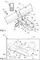
- eine erste Anhängekupplung mit einem an einer Halterung feststehenden Kupplungsarm in perspektivischer Ansicht von schräg oben und ein Bediengerät zu dessen Bedienung oder Überprüfung,
- Figur 2
- einen Kupplungsarm der Anhängekupplung gemäß
Figur 1 von schräg oben, - Figur 3
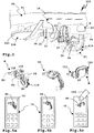
- eine zweite Anhängekupplung mit einem an einer Halterung beweglich gelagerten Kupplungsarm in perspektivischer Ansicht von schräg unten,
- Figur 4
- einen Kupplungsarm der Anhängekupplung gemäß
Figur 3 von schräg vorn, - Figur 5a
- die Anhängekupplung gemäß
Figur 3 in Gebrauchsstellung und ein Bediengerät zu dessen Bedienung, das diese Gebrauchsstellung anzeigt, - Figur 5b
- die Anordnung gemäß
Figur 5a , jedoch mit aus der Gebrauchsstellung verstelltem Kupplungsarm, - Figur 5c
- die Anordnung gemäß
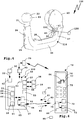
Figur 5a, 5b , jedoch mit in eine Nichtgebrauchsstellung verstelltem Kupplungsarm, - Figur 6
- eine schematische Darstellung eines Steuergeräts und eines Bediengeräts.
- Figure 1
- a first trailer coupling with a coupling arm fixed on a bracket in a perspective view obliquely from above and an operating device for its operation or checking,
- Figure 2
- a coupling arm of the trailer coupling according to
Figure 1 from diagonally above, - Figure 3
- a second trailer coupling with a coupling arm movably mounted on a bracket in a perspective view obliquely from below,
- Figure 4
- a coupling arm of the trailer coupling according to
Figure 3 from diagonally in front, - Figure 5a
- the trailer coupling according to
Figure 3 in the position of use and a control device for its operation, which displays this position of use, - Figure 5b
- the arrangement according to
Figure 5a , but with the coupling arm moved out of the position of use, - Figure 5c
- the arrangement according to
Figure 5a, 5b , but with the coupling arm moved into a non-use position, - Figure 6
- a schematic representation of a control device and an operating device.
In der Zeichnung sind Anhängekupplungen 10 und 110 dargestellt, die teilweise gleiche oder ähnliche Komponenten aufweisen, die dementsprechend mit den gleichen Bezugsziffern oder mit Bezugsziffern versehen sind, die bei der Anhängekupplung 110 um 100 größer sind als bei der Anhängekupplung 10.In the drawing, trailer hitches 10 and 110 are shown, some of which have the same or similar components, which are accordingly provided with the same reference numerals or with reference numerals that are 100 greater in the case of the
Die Anhängekupplungen 10, 110 weisen Halterungen 11, 111 auf, die an einem Kraftfahrzeug 90, zum Beispiel einem Personenkraftwagen, befestigbar sind.The trailer hitches 10, 110 have
Beispielsweise umfasst die Halterung 11 einen an einem Querträger 91 des Kraftfahrzeugs 90 angeordneten Grundhalter 12, von dem 2 Halteschenkel 13 abstehen. Zwischen den Halteschenkeln 13 ist ein Kupplungsarm 14 angeordnet. Der Kupplungsarm 14 ist mittels Schrauben 15, die Bohrungen 16 des Kupplungsarms 14 an einem fahrzeugseitigen Halteabschnitt 20 durchdringen, mit den Halteschenkeln 13 verschraubt. Somit ist also der Kupplungsarm 14 fest an der Halterung 11 befestigt. Von der Halterung 11 steht noch ein Steckdosenhalter 17 seitlich ab, an dem eine Anhängersteckdose (nicht dargestellt) befestigbar ist.For example, the
Bei der Anhängekupplung 110 ist eine am Kraftfahrzeug 90 befestigbare, zum Beispiel an einem nicht dargestellten Querträger befestigbare, Halterung 111 vorgesehen, die den Kupplungsarm 114 beweglich lagert. Beispielsweise ist der Kupplungsarm 114 um eine oder mehrere Drehachsen D1 und/oder D2 und/oder D3 schwenkbar und/oder verschieblich an der Halterung 111 gelagert. Ein Lagerkopf 118 der Halterung 111 greift in eine Lageraufnahme 119 an einem Halteabschnitt 20 des Kupplungsarms 114 am fahrzeugseitigen Endbereich des Kupplungsarms 114 ein, so dass eine Lagerung in der Art eines Kugelgelenks gegeben ist. Es versteht sich, dass auch andere Lagerkonzepte, beispielsweise Schiebelager, Schwenk-Schiebelager, mindestens ein Drehlager, insbesondere mehrere Drehlager mit zueinander winkeligen Drehachsen, kardanische Lagerungen oder dergleichen ohne weiteres möglich sind.In the case of the
Der Kupplungsarm 114 ist beispielsweise zwischen einer in Figur 3 dargestellten Gebrauchsstellung G, die zum Ziehen eines Anhängers 92 vorgesehen ist, und einer hinter einen Stoßfänger 94, beispielsweise näher an den Querträger zurück verstellten, Nichtgebrauchsstellung N verstellbar. Es sind dazwischen liegende Positionen Z1 und Z2 dargestellt. Der Kupplungsarm 114 ist zweckmäßigerweise durch einen Stellantrieb 39 zwischen den Stellungen N und G motorisch verstellbar, z.B. mittels eines elektrischen Motors, der den Kupplungsarm 114 direkt oder über einen Seilzug oder ein sonstiges Getriebe antreibt.The
Zusätzlich ist noch eine Verriegelung 35 vorhanden, um den Kupplungsarm 114 zumindest in der Gebrauchsstellung G zu verriegeln. Die Verriegelung 35 umfasst z.B. einen Verriegelungsbolzen 36, der Formstücke 37 in Verriegelungsaufnahmen an der Lageraufnahme 119 treibt. Der Verriegelungsbolzen 36 ist z.B. in die Verriegelungsstellung federbeaufschlagt und kann mittels eines Verriegelungsantriebs 38 in seine den Kupplungsarm 114 freigebende Entriegelungsstellung verstellen.In addition, there is also a
Die Kupplungsarme 14, 114 haben an ihren vom Kraftfahrzeug 90 entfernten Endbereichen 21 jeweils eine Kupplungskugel 22, die als Kuppelelement 23 zum Ankuppeln des Anhängers 92 (schematisch dargestellt) dient. Die Kupplungskugeln 22 sind an in der Gebrauchsstellung der Anhängekupplungen 10, 110 hoch stehenden Armabschnitten 24 vorgesehen. Die Armabschnitte 24 gehen mit einer Krümmung 25 in einen bei Gebrauch der Kupplungsarme 14, 114 im Wesentlichen horizontal verlaufenden Armabschnitt 26 über.The
Beim Kupplungsarm 14 sind der Armabschnitt 26 und der Endbereich 21 quasi einstückig, d.h. dass der Endbereich 21 an einem freien Ende des Armabschnitts 26 vorgesehen ist. Nachfolgend wird jedoch der frei vor die Halterung 11 vorstehende Abschnitt des Kupplungsarms 14 als Armabschnitt 26 bezeichnet.In the case of the
Beim Kupplungsarm 114 ist zwischen dem Halteabschnitt 20 und dem Armabschnitt 26 noch eine weitere Krümmung 27 vorhanden.In the
Die Anhängekupplungen 10, 110 sind dazu ausgestaltet, sowohl eine in einer vertikalen Richtung bzw. z-Richtung auf das Kuppelelement 23 wirkende Kraft, nachfolgend als Stützlast Fz bezeichnet, als auch eine in einer horizontalen Richtung bzw. x-Richtung auf das Kuppelelement 23 wirkende Last, nachfolgend als Zuglast Fx bezeichnet, zu messen. Dazu ist ein einziger Kraftsensor 30, beispielsweise ein Dehnungsmessstreifen 31, ausreichend. Dieser Kraftsensor 30 ist so optimal platziert, dass sein Sensorsignal 33 sowohl die Zuglast Fx als auch die Stützlast Fz repräsentiert.The trailer hitches 10, 110 are designed to have both a force acting on the
In den
Auch die Anhängekupplung 110 kommt mit einem einzigen Kraftsensor 30 aus. Bei Belastung des Kupplungsarms 114 mit einer Zuglast Fx und auch einer Stützlast Fz bildet sich beispielsweise ein Verformungsbereich 42 an der Innenseite der Krümmung 27 aus. Der Kraftsensor 30 ist in der Krümmung 27 angeordnet. Dort ist der Kraftsensor 30 vor Umwelteinflüssen zudem noch durch den Stoßfänger 94 des Kraftfahrzeugs 90 geschützt.The
An den Anhängekupplungen 10, 110 sind Steuergeräte 50, 150 vorgesehen, die Steuerungsfunktionen und/oder Auswertefunktionen realisieren. Insofern könnte man bei einem Steuergerät gemäß der Erfindung durchaus auch von einem Auswertegerät sprechen, wenn es keine eigene Steuerungsfunktion hat. Zur Vereinfachung sind jedoch die Steuergeräte 50, 150 als Steuergeräte bezeichnet, auch wenn im Falle des Steuergeräts 50 eigentlich eher die Bezeichnung Auswerte-Gerät berechtigt wäre.
Die Steuergeräte 50, 150 sind beispielsweise über Leitungen 51 mit den Dehnungsmessstreifen 31 bzw. den Kraftsensoren 30 verbunden, um so beispielsweise eine Stützlast Fz zu ermitteln, die auf dem Kuppelelement 23 von oben her auflastet oder auch eine Zugkraft Fx, die in Fahrtrichtung des Kraftfahrzeugs 90 auf das Kuppelelement 23 wirkt.The
Die Steuergeräte 50, 150 umfassen beispielsweise einen Prozessor 52, der Programmcode eines Auswertemoduls 54 auswertet, das in einem Speicher 53 des Steuergeräts 50, 150 gespeichert ist. Das Auswertemodul 54 wertet dazu das Sensorsignal 33, das über die Leitung 51 an das Steuergerät 50 oder 150 übermittelt wird, aus. Die Leitung 51 ist an einen Sensoreingang 62 des Steuergeräts 50 oder 150 angeschlossen.The
Dieses Sensorsignal 33 repräsentiert im Stillstand des Kraftfahrzeugs 90 die Stützlast bzw. ermöglicht die Ermittlung der Stützlast Fz. Um aus dem Sensorsignal 33 auch eine Masse des Anhängers 92 zu bestimmen, hat das Steuergerät 50 oder 150 einen Beschleunigungssensor 55 an Bord oder eine Schnittstelle für ein Geschwindigkeits- oder Beschleunigungssignal. Bei einem Fahrbetrieb des Kraftfahrzeugs 90 bzw. des Gespanns bestehend aus Kraftfahrzeug 90 und Anhänger 92 ist somit aus dem Sensorsignal 33 eine Masse des Anhängers bestimmbar, wofür beispielsweise die Beschleunigung vom Auswertemodul 54 ausgewertet wird, die der Beschleunigungssensor 55 ermittelt.This
Nun kann bei einem erfindungsgemäßen Steuergerät eine lokale Anzeige vorhanden sein, beispielsweise ein Display 56, das direkt am Kupplungsarm 14 angeordnet ist und dort beispielsweise die Stützlast oder die Masse des Anhängers 92 anzeigt.A local display can now be present in a control device according to the invention, for example a
Man kann sich vorstellen, dass eine solche lokale Anzeige nicht in jeder Situation bequem ablesbar ist. Insbesondere sind die grafischen Möglichkeiten sehr begrenzt. Darüber hinaus ist es nicht unbedingt vorteilhaft, im Außenbereich, d.h. dort wo die Umwelteinflüsse auf ein erfindungsgemäßes Steuergerät wirken, eine Anzeige vorzusehen. Die Anzeige ist nämlich Verschmutzung und Zerstörung ausgesetzt.One can imagine that such a local display is not easy to read in every situation. In particular, the graphic options are very limited. Furthermore, it is not necessarily advantageous to use outdoors, i. to provide a display where the environmental influences act on a control device according to the invention. This is because the display is subject to pollution and destruction.
Bei dem Steuergerät 150 ist eine lokale Anzeige fast schon unmöglich, da es unmittelbar unter dem Querträger 91 und hinter dem Stoßfänger 94 für den Bediener normalerweise verborgen untergebracht ist.In the case of the
Das Steuergerät 150 realisiert zudem noch eine Steuerungsfunktion dahingehend, dass es Steuerausgänge 57 und 58 zum Ansteuern des Verriegelungsantriebs 38 und des Stellantriebs 39 aufweist. Zur Ansteuerung der Steuerausgänge 57 und 58 ist ein Steuermodul 59 vorgesehen, das im vorliegenden Fall ebenfalls in Software realisiert ist, d.h. dass sein Programmcode vom Prozessor 52 ausführbar ist. Selbstverständlich ist es denkbar, dass beispielsweise das Steuermodul 59 und/oder das Auswertemodul 54 auch in Hardware realisiert sind, beispielsweise als programmierbares Gatter, zum Beispiel als FPGA.The
In diesem Zusammenhang sei auch erwähnt, dass in dem Blockschaltbild gemäß
Das Auswertemodul 54 bildet, wenn sein Programmcode vom Prozessor 52 ausgeführt wird, ein Auswertemittel 60. Das Steuermodul 59 bildet, wenn sein Programmcode vom Prozessor 52 ausgeführt wird, ein Steuermittel 61. Das Steuermittel 61 überwacht beispielsweise, ob eine Verriegelung korrekt stattfindet, wofür eine entsprechende Verriegelungssensorik vorgesehen sein kann. Auch die Bewegungsabläufe bei der Anhängekupplung 110 werden von dem Steuermittel 61 überwacht und gesteuert, so dass zum Beispiel zunächst der Verriegelungsantrieb oder Entriegelungsantrieb 38 den Kupplungsarm 114 entriegelt, bevor der Stellantrieb 39 die Stellung des Kupplungsarms 114 verstellt.The
Das Steuergerät 50, 150 hat zweckmäßigerweise eine Bordnetz-Schnittstelle 63 zur Kommunikation mit einem Bordnetz 93 des Kraftfahrzeugs 90. Das Bordnetz 93 umfasst zweckmäßigerweise einen Datenbus, zum Beispiel einen CAN oder LIN Bus, so dass die Bordnetz-Schnittstelle 63 zweckmäßigerweise eine BusSchnittstelle umfasst. Vorzugsweise wird das Steuergerät 50, 150 über die Bordnetz-Schnittstelle 63 mit elektrischer Energie versorgt.The
Auf diesem Wege kann zum Beispiel das Steuergerät 150 eine Anhängersteckdose 32 mit elektrischer Energie versorgen bzw. diese ansteuern, so dass elektrische Kontakte 34, beispielsweise an sich bekannte Steckbuchsen, bestromt werden und nicht dargestellte Leuchten des Anhängers 92 elektrische Energie erhalten, wenn ein nicht dargestellter Stecker des Anhängers 92 in die Anhängersteckdose 32 eingesteckt ist.In this way, for example, the
Die Steuergeräte 50 oder 150 sind bei der in der Zeichnung dargestellten Bauweise jeweils in Gehäusen 65, 165 untergebracht, die dediziert für die Steuergeräte vorgesehen sind. Es wäre aber auch denkbar, z.B. das Steuergerät 150 im Gehäuse der Anhängersteckdose 32 unterzubringen.In the construction shown in the drawing, the
Die Steuergeräte 50, 150 ermöglichen eine bequeme Bedienung, indem sie zur Kommunikation mit einem mobilen, externen Bediengerät 70 ausgestaltet sind, beispielsweise einem Mobilfunk-Telefon, einem Smartphone, einem Tablet-PC oder dergleichen. Das zur Kommunikation mit dem Steuergerät 50 und/oder 150 vorgesehene Bediengerät 70 hat ein Programmmodul 71 an Bord, mit dem es die Kommunikation und komfortable Bedienung des Steuergeräts 50 oder 150 und/oder Ausgabe von Daten des Steuergeräts 50 oder 150 realisiert, wobei das Programmmodul 71 eine grafische Oberfläche an einem Display 76 des Bediengeräts 70 erzeugt.The
Das Programmmodul 71 enthält Programmcode, der von einem Prozessor 72 ausführbar ist. Das Programmmodul 71 ist beispielsweise in einem Speicher 73 des Bediengeräts 70 gespeichert. Das Programmmodul 71 ist zweckmäßigerweise in das Bediengerät 70 ladbar, zum Beispiel aus dem Internet und/oder über eine sonstige Ladeschnittstelle, zum Beispiel über eine USB-Schnittstelle oder drahtlos, beispielsweise über eine Bluetooth-Schnittstelle 74.The
An dem Display 76 kann das Bediengerät 70 eine grafische Bedienoberfläche 77 darstellen, über die das Bediengerät 70 selbst und/oder das Steuergerät 50 und/oder 150 bedienbar ist. Insoweit die Bedienoberfläche77 zur Bedienung des Steuergeräts 50 oder 150 vorgesehen ist, steuert das Programmmodul 71 das Display 76 an, beispielsweise direkt oder unter Nutzung von Betriebsmitteln des Bediengeräts 70, beispielsweise dessen nicht weiter erläuterten Betriebssystems.On the
Das Steuergerät 50 oder 150 hat eine Bediengerät-Schnittstelle 64 zur Kommunikation mit dem Bediengerät 70. Die Bediengeräts-Schnittstelle 64 umfasst beispielsweise ein Bluetooth-Modul 67, also eine drahtlose Schnittstelle. Somit kann also das Steuergerät 50 oder 150 ein Meldesignal 80, das beispielsweise das Sensorsignal 33 oder daraus generierte Daten, zum Beispiel die Masse des Anhängers 92, die Stützlast, die auf dem Kupplungsarm 14, 114 lastet oder dergleichen, an das Bediengerät 70 senden, welches unter Nutzung des Programmmoduls 71 an der grafischen Bedienoberfläche 77 das Meldesignal 80 ausgibt.The
Dabei ist es möglich, dass an der Bedienoberfläche 77 beispielsweise aus dem Meldesignal 80 generierte Zahlenwerte ausgegeben werden.It is possible here for numerical values generated from the
Vorteilhaft ist es, wenn das Programmmodul 71 die Daten des Meldesignals 80 quasi aufbereitet. So kann beispielsweise an dem Display 76 ein Symbol 78 bzw. eine grafische Repräsentanz des Kupplungsarms 14 oder 114 angezeigt werden (
Die grafischen Daten, mit denen das Symbol 78 erzeugt wird, können beispielsweise direkt vom Programmmodul 71 generiert werden. Somit kann also beispielsweise die Leistung des Prozessors 52 relativ gering sein, während die eigentliche grafische Ausgabe der Daten des Meldesignals 80 vom Prozessor 72 geleistet wird, der hierfür ohnehin schon ausgelegt ist.The graphic data with which the
Es ist auch möglich, dass das Steuergerät 50 oder 150 entsprechende grafische Daten an das Bediengerät 70 bzw. das Programmmodul 71 sendet, so dass dort relativ wenig Intelligenz zur Ausgabe der Daten notwendig ist.It is also possible for the
Selbstverständlich kann das Programmmodul 71 auch Warnmeldungen, die im Rahmen des Meldesignals 80 übertragen werden oder die das Programmmodul 71 anhand des Meldesignals 80 generiert, beispielsweise bei Überbelastung der Anhängekupplung, anhand der Ausgabemittel des Bediengeräts 70 ausgeben, beispielsweise am Display 76, über einen nicht dargestellten Lautsprecher des Bediengeräts 70 oder dergleichen.Of course, the
Der Bediener kann beispielsweise anhand von Eingabemitteln 75 des Bediengeräts 70, zum Beispiel Tasten, auswählen, welche Daten an der Bedienoberfläche 77 angezeigt werden sollen, beispielsweise die Masse des Anhängers 92, die jeweilige Stützlast oder dergleichen. Es ist auch möglich, dass an der Bedienoberfläche 77 vom Programmmodul 71 ein Auswahlmenü generiert wird, bei dem das Programmmodul 71 bei Druck auf entsprechende Flächen 79a, 79b, die ein Auswahlmenü bilden, oder unter den Flächen 79 liegende Tasten der Eingabemittel 75 ein Steuersignal 81 erzeugt, das über die Schnittstelle 74 zur Schnittstelle 64 des Steuergeräts 50 oder 150 übertragen wird und dieses dazu anweist, beispielsweise mit dem Meldesignal die entsprechenden Daten an das Bediengerät 70 zu übermitteln, beispielsweise die Masse des Anhängers 92, die Stützlast oder dergleichen. Somit interagieren also das Steuergerät 50, 150 einerseits und das Bediengerät 70 bzw. dessen Programmmodul 71 andererseits miteinander, um Daten an dem Display 76 auszugeben.The operator can, for example, using input means 75 of the operating
An dieser Stelle sei bemerkt, dass selbstverständlich auch eine Sprachausgabe am Bediengerät 70 möglich ist, das heißt dass beispielsweise die Masse des Anhängers 92 von einer synthetischen Stimme gesprochen wird.At this point it should be noted that voice output is of course also possible on the operating
Neben dieser Befehlseingabe am Bediengerät 70, die zur Datenabfrage dient, liegt auch eine Befehlseingabe zur direkten Steuerung eines erfindungsgemäßen Steuergeräts bzw. einer Anhängekupplung im Rahmen der Erfindung:
Beispielsweise kann das Programmmodul 71, was in den
For example, the
Über die Meldesignale 80 meldet das Steuergerät die Position des Kupplungsarms 114 an das Bediengerät 70, welches die Stellung des Symbols 84 an der Bedienoberfläche 77 entsprechend nachführt bzw. anpasst.The control device reports the position of the
Der Bediener kann also bequem hinter dem Kraftfahrzeug 90 stehen, das Bediengerät 70 in der Hand halten und über das Display 76 streichen, um den Kupplungsarm 114 zu verstellen. Diese Bedienung ist äußerst komfortabel.The operator can thus comfortably stand behind the
Selbstverständlich ist es vorteilhaft, wenn nicht jeder beliebige Nutzer, der beispielsweise das Programmmodul 71 auf sein Mobilfunk-Telefon lädt, die Anhängekupplungen 10, 110 bedienen und/oder deren Daten abfragen kann.It is of course advantageous if not every user who, for example, loads the
So kann beispielsweise die Bediengerät-Schnittstelle 64 eine Bluetooth-Schnittstelle mit dem Bluetooth-Modul 67 umfassen, die nur mit einem entsprechenden Zugangscode aktivierbar bzw. nutzbar ist. Ein Bediener muss also beispielsweise am Bediengerät 70 einen Zugangsschlüssel 83 eingeben, mit dem sich das Bluetooth-Modul bzw. die Bluetooth-Schnittstelle 74 des Bediengeräts 70 beim Steuergerät 50 oder 150 anmeldet.For example, the operating
Es ist auch möglich, dass das Programmmodul 71 beispielsweise anhand einer im Bediengerät 70 enthaltenen Kamera 86 einen optischen Code 85 einliest und anhand des Codes 85 einen Zugangsschlüssel generiert, zum Beispiel den Zugangsschlüssel 83, und/oder optische Daten des Codes 85 selbst an das Steuergerät 50 oder 150 übermittelt, wo ein Authentifizierungsmodul 66, dessen Programmcode ebenfalls vom Prozessor 52 ausführbar ist, die Zugangsdaten überprüft, zum Beispiel den optischen Code 85 bzw. den daraus generierten Zugangsschlüssel. Erst wenn diese Daten in Ordnung sind, ist es möglich, mit dem Bediengerät 70 Daten beim Steuergerät 50 oder 150 abzufragen und/oder das Steuergerät 50 oder 150 bzw. die zugeordnete Anhängekupplung 10, 110, zu steuern. Das Authentifizierungsmodul 66 bildet ein Authentifizierungsmittel.It is also possible for the
Es ist auch möglich, dass das Steuergerät 50 oder 150 das Bordnetz 93 alternativ oder in Ergänzung zu seiner eigenen drahtlosen Schnittstelle 67 dazu nutzt, um mit dem Bediengerät 70 zu kommunizieren. Z.B. kann an das Bordnetz 93 ein Bluetooth-Modul, WLAN-Modul oder dergleichen sonstiges drahtlos kommunizierendes Modul angeschlossen sein, so dass das Bordnetz 93 eine drahtlose Schnittstelle 95 aufweist. Über die Bordnetz-Schnittstelle 63 kann das Steuergerät 50 oder 150 die drahtlose Schnittstelle 95 zur Kommunikation mit dem Bediengerät 70 nutzen.It is also possible that the
Claims (13)
- Trailer coupling (10; 110) which may be mounted on a motor vehicle (90), wherein the trailer coupling (10; 110) has a coupling element (23) mounted on a coupling arm (14; 114) for attaching a trailer (92) and a control unit (50; 150), wherein the control unit (50; 150) has control means (61) for controlling at least one function of the trailer coupling (10; 110), wherein the control unit (50; 150) has an operator unit interface (64) for communication with a mobile operator unit (70) separate from the motor vehicle (90) and the control unit (50; 150), and wherein the control unit (50; 150) has at least one control output (57; 58) for controlling or switching a drive (38, 39) of the trailer coupling (10; 110), characterised in that the control unit (50; 150) is designed for communication with a program module (71) generating a graphical display and/or user interface (77) on a display of the operator unit (70), in particular in the form of a mobile radio telephone, and that the control unit (50; 150) is designed for receiving at least one control signal (81; 82) for controlling a function or functions of the control unit (50; 150) via the operator unit interface (64), and that it is designed to activate the control output or outputs (57; 58) with the aid of the at least one control signal (81; 82) received via the operator unit interface (64).
- Trailer coupling (10; 110) according to claim 1, characterised in that the control unit (50; 150) has evaluation means (60) for the evaluation of at least one sensor signal (33) of a sensor (30) assigned to the trailer coupling (10; 110) and that the control unit (50; 150) is designed for the sending of at least one status signal (80) representing a status of the trailer coupling (10; 110), in particular with the aid of the sensor signal or signals (33) generated or containing the sensor signal or signals (33), via the operator unit interface (64).
- Trailer coupling (10; 110) according to claim 1 or 2, characterised in that the control unit (50; 150) has authentication means for verifying authorisation of the operator unit (70) for communication with the control unit (50; 150), wherein it is advantageously provided that the authentication means are designed for verifying at least one access code (83) or identification code or password, which the control unit (50; 150) receives from the operator unit (70) via the operator unit interface (64).
- Trailer coupling (10; 110) to any of the preceding claims, characterised in that the operator unit interface (64) or a part of the operator unit interface (64) is located onboard the control unit (50; 150), in particular inside a housing (65; 165) of the control unit (50; 150), and/or that it includes a vehicle electrical system interface (63) for communication with a vehicle electrical system (93) of the motor vehicle (90).
- Trailer coupling (10; 110) according to claim 4, characterised in that the control unit (50; 150) is designed for the transmission to the operator unit (70) of data received over the vehicle electrical system interface (63) via its operator unit interface (64), in particular wireless, and/or for the transmission to the vehicle electrical system (93) via the vehicle electrical system interface (63) of data obtained over its operator unit interface (64), in particular wireless, from the operator unit (70) and/or that it is designed for communication with the mobile operator unit (70) via the vehicle electrical system (93) and a wireless interface (95) connected to the vehicle electrical system (93) and provided for communication with the mobile operator unit (70).
- Trailer coupling (10; 110) according to any of the preceding claims, characterised in that the operator unit interface (64) comprises a wireless interface, in particular a Bluetooth interface and/or a WLAN interface, and/or that it is located in a housing of a trailer socket (32) for the supply of power to a trailer (92) or load carrier.
- Trailer coupling (10; 110) according to any of the preceding claims, characterised in that the drive (38, 39) is a locking drive (38) provided for locking the coupling arm (14; 114) and in particular comprising or forming an unlocking drive, and/or an actuator (39) of the trailer coupling (10; 110) provided for adjustment of the coupling arm (14; 114).
- Trailer coupling (10; 110) according to any of the preceding claims, characterised in that the control unit (50; 150) has a sensor input (62) for a sensor (30) located on the trailer coupling (10; 110), in particular the coupling arm (14; 114) or the coupling element (23), and/or a sensor (55) located onboard the control unit (50; 150).
- Trailer coupling (10; 110) according to any of the preceding claims, characterised in that the control unit (50; 150) is designed for the activation of electrical contacts (34) of a trailer socket (32) provided for the electrical power supply of at least one lamp of a trailer (92) or load carrier, and that it is designed for activation of the electrical contacts (34), in particular for checking the lamp or lamps as a result of a control signal (81; 82) received over the operator unit interface (64).
- Trailer coupling (10; 110) according to any of the preceding claims, characterised in that the control unit (50; 150) is designed for the output at the operator unit interface (64) of data received via a communications interface, in particular via a trailer socket (32), from the trailer (92) or the load carrier, in particular data of a parking distance control device of the trailer (92) or the load carrier.
- Trailer coupling (10; 110) according to any of the preceding claims, characterised in that the control unit (50; 150) forms part of a system which includes the control unit (50; 150) and the operator unit (70) which is especially wireless, in particular in the form of a smartphone.
- System comprising a trailer coupling (10; 110) according to any of claims 1 to 11, together with an operator unit (70), in particular mobile radio telephone or smartphone, for communication with the the control unit (50; 150),with a program module (71), wherein the program module (71) contains program code which may be executed by a processor of the operator unit (70), wherein the program code is designed, on execution by the processor, to generate a graphical display and/or user interface (77) at a display of the operator unit (70) and to generate with the aid of an operation detected at the operator unit (70), in particular via the user interface (77), the control signal or signals (81; 82) for the control unit (50; 150).
- System according to claim 12, characterised in that the program code is designed, on execution by the processor, to output at the display and/or user interface (77) the status signal or signals (80) received by the control unit (50; 150), and/or that the program module is designed for the output of a selection menu at the graphical display and/or user interface (77) of the operator unit (70) wherein, with the aid of the selection menu, the retrieval and/or output of data from the control unit (50; 150) and/or a control interface for the generation of the control signal or signals (81; 82) is selectable, and/or that it is designed to generate a touch-sensitive user interface (77) or for interaction with a touch-sensitive user interface (77), in particular for control of the trailer coupling.
Priority Applications (2)
| Application Number | Priority Date | Filing Date | Title |
|---|---|---|---|
| EP21160871.6A EP3868581A1 (en) | 2011-12-09 | 2012-11-27 | Controller and trailer coupling for communication with a control unit |
| EP19164531.6A EP3536524B1 (en) | 2011-12-09 | 2012-11-27 | Controller and trailer coupling for communication with a control unit |
Applications Claiming Priority (2)
| Application Number | Priority Date | Filing Date | Title |
|---|---|---|---|
| DE102011120651A DE102011120651A1 (en) | 2011-12-09 | 2011-12-09 | Control unit and trailer coupling for communication with an operator panel |
| EP12007964.5A EP2602133B2 (en) | 2011-12-09 | 2012-11-27 | Controller and trailer coupling for communication with an operating device |
Related Parent Applications (3)
| Application Number | Title | Priority Date | Filing Date |
|---|---|---|---|
| EP12007964.5A Division EP2602133B2 (en) | 2011-12-09 | 2012-11-27 | Controller and trailer coupling for communication with an operating device |
| EP12007964.5A Previously-Filed-Application EP2602133B2 (en) | 2011-12-09 | 2012-11-27 | Controller and trailer coupling for communication with an operating device |
| EP12007964.5A Division-Into EP2602133B2 (en) | 2011-12-09 | 2012-11-27 | Controller and trailer coupling for communication with an operating device |
Related Child Applications (3)
| Application Number | Title | Priority Date | Filing Date |
|---|---|---|---|
| EP21160871.6A Division EP3868581A1 (en) | 2011-12-09 | 2012-11-27 | Controller and trailer coupling for communication with a control unit |
| EP19164531.6A Division-Into EP3536524B1 (en) | 2011-12-09 | 2012-11-27 | Controller and trailer coupling for communication with a control unit |
| EP19164531.6A Division EP3536524B1 (en) | 2011-12-09 | 2012-11-27 | Controller and trailer coupling for communication with a control unit |
Publications (2)
| Publication Number | Publication Date |
|---|---|
| EP3159193A1 EP3159193A1 (en) | 2017-04-26 |
| EP3159193B1 true EP3159193B1 (en) | 2020-09-23 |
Family
ID=47594192
Family Applications (4)
| Application Number | Title | Priority Date | Filing Date |
|---|---|---|---|
| EP19164531.6A Active EP3536524B1 (en) | 2011-12-09 | 2012-11-27 | Controller and trailer coupling for communication with a control unit |
| EP21160871.6A Pending EP3868581A1 (en) | 2011-12-09 | 2012-11-27 | Controller and trailer coupling for communication with a control unit |
| EP12007964.5A Active EP2602133B2 (en) | 2011-12-09 | 2012-11-27 | Controller and trailer coupling for communication with an operating device |
| EP16194620.7A Active EP3159193B1 (en) | 2011-12-09 | 2012-11-27 | Trailer coupling with a controller for communication with an operator device |
Family Applications Before (3)
| Application Number | Title | Priority Date | Filing Date |
|---|---|---|---|
| EP19164531.6A Active EP3536524B1 (en) | 2011-12-09 | 2012-11-27 | Controller and trailer coupling for communication with a control unit |
| EP21160871.6A Pending EP3868581A1 (en) | 2011-12-09 | 2012-11-27 | Controller and trailer coupling for communication with a control unit |
| EP12007964.5A Active EP2602133B2 (en) | 2011-12-09 | 2012-11-27 | Controller and trailer coupling for communication with an operating device |
Country Status (2)
| Country | Link |
|---|---|
| EP (4) | EP3536524B1 (en) |
| DE (1) | DE102011120651A1 (en) |
Families Citing this family (16)
| Publication number | Priority date | Publication date | Assignee | Title |
|---|---|---|---|---|
| DE102013007726A1 (en) | 2013-05-07 | 2014-11-13 | Westfalia-Automotive Gmbh | Trailer coupling with an evaluation device |
| DE102013106445A1 (en) * | 2013-06-20 | 2014-12-24 | I-vector Innovationsmanagement GmbH | Method for the safe operation of vehicle-related applications |
| EP3078514B1 (en) | 2015-04-07 | 2021-09-01 | WESTFALIA - Automotive GmbH | System with a control device and an operating device |
| DE102015108526A1 (en) | 2015-04-07 | 2016-10-13 | Westfalia-Automotive Gmbh | System with a control unit and a control unit |
| DE102017102504A1 (en) | 2017-02-08 | 2018-08-09 | Bosal Acps Holding 2 B.V. | Towing |
| DE102017102505A1 (en) | 2017-02-08 | 2018-08-09 | Bosal Acps Holding 2 B.V. | Towing |
| DE102017129455A1 (en) * | 2017-02-14 | 2018-08-16 | Westfalia-Automotive Gmbh | Clutch control module for a trailer hitch |
| EP3379222B1 (en) | 2017-03-22 | 2020-12-30 | Methode Electronics Malta Ltd. | Magnetoelastic based sensor assembly |
| DE102017213774A1 (en) * | 2017-08-08 | 2019-02-14 | Audi Ag | Method for operating a motor vehicle |
| US11491832B2 (en) | 2018-02-27 | 2022-11-08 | Methode Electronics, Inc. | Towing systems and methods using magnetic field sensing |
| US11084342B2 (en) | 2018-02-27 | 2021-08-10 | Methode Electronics, Inc. | Towing systems and methods using magnetic field sensing |
| US11221262B2 (en) | 2018-02-27 | 2022-01-11 | Methode Electronics, Inc. | Towing systems and methods using magnetic field sensing |
| US11135882B2 (en) | 2018-02-27 | 2021-10-05 | Methode Electronics, Inc. | Towing systems and methods using magnetic field sensing |
| WO2019168565A1 (en) | 2018-02-27 | 2019-09-06 | Methode Electronics,Inc. | Towing systems and methods using magnetic field sensing |
| DE102018124549A1 (en) * | 2018-10-04 | 2020-04-09 | Westfalia-Automotive Gmbh | Trailer coupling |
| DE102021101173A1 (en) | 2021-01-20 | 2022-07-21 | Westfalia-Automotive Gmbh | Clutch control module for a trailer hitch |
Citations (12)
| Publication number | Priority date | Publication date | Assignee | Title |
|---|---|---|---|---|
| US5650764A (en) | 1994-08-25 | 1997-07-22 | Mccullough; Deborah Y. | Trailer alignment device with visual display |
| EP1282298A2 (en) * | 2001-07-30 | 2003-02-05 | KNORR-BREMSE SYSTEME FÜR NUTZFAHRZEUGE GmbH | Communication device for vehicles |
| DE20203270U1 (en) | 2002-02-28 | 2003-07-10 | Kober Ag | Towing device for towing vehicles comprises a tow bar movably mounted about two axes of rotation, and a mechanical drive having a mechanism for generating a superimposed movement of the tow bar about both axes |
| US6663132B1 (en) | 2002-09-23 | 2003-12-16 | The United States Of America As Represented By The Secretary Of The Army | Remotely controlled electro-hydraulic towing assembly |
| US20050285371A1 (en) | 2004-06-23 | 2005-12-29 | Ramsey J E | Trailer alignment device |
| DE102004037707A1 (en) * | 2004-08-04 | 2006-02-23 | Daimlerchrysler Ag | Wireless remote control system for vehicle functions |
| EP1407901B1 (en) | 2002-10-09 | 2006-05-17 | Al-Ko Kober Ag | Towing hitch for towing vehicles |
| EP1985473A1 (en) | 2007-04-25 | 2008-10-29 | WESTFALIA - Automotive GmbH | Draw bar with an actuation device |
| DE202009005185U1 (en) | 2009-08-26 | 2011-01-20 | Al-Ko Kober Ag | auxiliary drive |
| EP2280263A2 (en) | 2009-07-30 | 2011-02-02 | Hein, Herr Thomas | Supporting load measuring device and retrofitting method for a vehicle trailer device |
| CN202053849U (en) | 2011-03-07 | 2011-11-30 | 安阳市天达自动化有限责任公司 | Wireless remote-control automatic decoupling device for vehicles |
| EP2502762A1 (en) | 2011-03-23 | 2012-09-26 | WESTFALIA - Automotive GmbH | Control device for a tow bar and tow bar with a control device |
Family Cites Families (7)
| Publication number | Priority date | Publication date | Assignee | Title |
|---|---|---|---|---|
| DE20320506U1 (en) * | 2002-06-06 | 2004-12-23 | Wagner, Guido | System with vehicle and coupled trailer, has wireless connection forming vehicle and trailer interfaces enabling data communications between vehicle and trailer using electromagnetic waves or ultrasound |
| DE10335955A1 (en) * | 2003-08-06 | 2005-02-24 | Afusoft Kommunikationstechnik Gmbh | Active, local and remotely controlled latching and de-latching of towing vehicle coupling to trailer, involves remote control via satellite communication and/or RF |
| US9503562B2 (en) | 2008-03-19 | 2016-11-22 | Universal Electronics Inc. | System and method for appliance control via a personal communication or entertainment device |
| DE102008034848A1 (en) | 2008-06-06 | 2009-12-17 | Westfalia-Automotive Gmbh | Towing |
| JP5326794B2 (en) | 2009-05-15 | 2013-10-30 | トヨタ自動車株式会社 | Remote operation system and remote operation method |
| US8138899B2 (en) | 2009-07-01 | 2012-03-20 | Ford Global Technologies, Llc | Rear camera backup assistance with touchscreen display using two points of interest |
| CN101604153B (en) | 2009-07-06 | 2011-06-29 | 三一重工股份有限公司 | Engineering vehicle arm rest controller, control system, engineering vehicle and control method |
-
2011
- 2011-12-09 DE DE102011120651A patent/DE102011120651A1/en active Pending
-
2012
- 2012-11-27 EP EP19164531.6A patent/EP3536524B1/en active Active
- 2012-11-27 EP EP21160871.6A patent/EP3868581A1/en active Pending
- 2012-11-27 EP EP12007964.5A patent/EP2602133B2/en active Active
- 2012-11-27 EP EP16194620.7A patent/EP3159193B1/en active Active
Patent Citations (12)
| Publication number | Priority date | Publication date | Assignee | Title |
|---|---|---|---|---|
| US5650764A (en) | 1994-08-25 | 1997-07-22 | Mccullough; Deborah Y. | Trailer alignment device with visual display |
| EP1282298A2 (en) * | 2001-07-30 | 2003-02-05 | KNORR-BREMSE SYSTEME FÜR NUTZFAHRZEUGE GmbH | Communication device for vehicles |
| DE20203270U1 (en) | 2002-02-28 | 2003-07-10 | Kober Ag | Towing device for towing vehicles comprises a tow bar movably mounted about two axes of rotation, and a mechanical drive having a mechanism for generating a superimposed movement of the tow bar about both axes |
| US6663132B1 (en) | 2002-09-23 | 2003-12-16 | The United States Of America As Represented By The Secretary Of The Army | Remotely controlled electro-hydraulic towing assembly |
| EP1407901B1 (en) | 2002-10-09 | 2006-05-17 | Al-Ko Kober Ag | Towing hitch for towing vehicles |
| US20050285371A1 (en) | 2004-06-23 | 2005-12-29 | Ramsey J E | Trailer alignment device |
| DE102004037707A1 (en) * | 2004-08-04 | 2006-02-23 | Daimlerchrysler Ag | Wireless remote control system for vehicle functions |
| EP1985473A1 (en) | 2007-04-25 | 2008-10-29 | WESTFALIA - Automotive GmbH | Draw bar with an actuation device |
| EP2280263A2 (en) | 2009-07-30 | 2011-02-02 | Hein, Herr Thomas | Supporting load measuring device and retrofitting method for a vehicle trailer device |
| DE202009005185U1 (en) | 2009-08-26 | 2011-01-20 | Al-Ko Kober Ag | auxiliary drive |
| CN202053849U (en) | 2011-03-07 | 2011-11-30 | 安阳市天达自动化有限责任公司 | Wireless remote-control automatic decoupling device for vehicles |
| EP2502762A1 (en) | 2011-03-23 | 2012-09-26 | WESTFALIA - Automotive GmbH | Control device for a tow bar and tow bar with a control device |
Also Published As
| Publication number | Publication date |
|---|---|
| EP3159193A1 (en) | 2017-04-26 |
| EP2602133B1 (en) | 2016-12-28 |
| EP2602133A1 (en) | 2013-06-12 |
| EP3536524A1 (en) | 2019-09-11 |
| EP3536524B1 (en) | 2021-04-14 |
| EP2602133B2 (en) | 2022-08-10 |
| EP3868581A1 (en) | 2021-08-25 |
| DE102011120651A1 (en) | 2013-06-13 |
Similar Documents
| Publication | Publication Date | Title |
|---|---|---|
| EP3159193B1 (en) | Trailer coupling with a controller for communication with an operator device | |
| EP2990311B1 (en) | Kit for the wireless control of a shunt drive system for a vehicle, shunt drive system and vehicle | |
| EP1926069B1 (en) | Radio remote control | |
| EP2767417B1 (en) | hitch with a positioning drive assembly | |
| EP1982812B2 (en) | Control for mixer truck | |
| WO2013189743A2 (en) | Vehicle having an electronically controlled vehicle device that can be operated by a driver | |
| DE102010053393A1 (en) | Method and system for communication with motor vehicles | |
| EP2701938A1 (en) | Interface for wireless data transmission in a motor vehicle, and computer program product | |
| DE102014113766A1 (en) | Systems and methods for notifying vehicle status | |
| EP3123687B1 (en) | Authorization method in a wireless vehicle network | |
| DE102006043004A1 (en) | Wind stop device | |
| DE102014115250A1 (en) | SYSTEM FOR CONTROLLING VEHICLE FUNCTIONS | |
| DE102013015738A1 (en) | System for coupling vehicle to trailer, has input unit and output unit with mobile unit that are adapted to perform given interactive program for controlling control unit for remote-controlled coupling of vehicle to trailer | |
| DE102019124513A1 (en) | Motor vehicle | |
| DE102005014939A1 (en) | Actuator for vehicle computer, has mobile guides movably arranged and freely adjustable to limit movement of control units on switching surface between control actions with respect to coordinates of centerlines | |
| DE102015111911A1 (en) | Display and input system for an agricultural machine | |
| DE202011100804U1 (en) | By a mobile user terminal controllable vehicle information and / or entertainment device | |
| EP3549850A1 (en) | Mounting device comprising a controller | |
| DE102012020697A1 (en) | Device for adjusting air guiding device e.g. spoiler, for vehicle i.e. lorry, has adjusting unit driven by operating device that has wireless remote controller, cable-bonded remote controller, operating unit, and communication device | |
| DE102013013328A1 (en) | System for integrating a mobile terminal in a vehicle operating concept | |
| DE102015215332B4 (en) | Vehicle key for informing a user about a status of a means of transportation | |
| DE102015009746A1 (en) | Motor vehicle comprising at least one seat with a headrest | |
| EP3078514B1 (en) | System with a control device and an operating device | |
| DE102018213554A1 (en) | Method and display device for visualizing an arrangement and mode of operation of environmental sensors of a motor vehicle | |
| DE202014103989U1 (en) | Kit for the wireless control of a shunting drive system for a vehicle, shunting drive system and vehicle |
Legal Events
| Date | Code | Title | Description |
|---|---|---|---|
| PUAI | Public reference made under article 153(3) epc to a published international application that has entered the european phase |
Free format text: ORIGINAL CODE: 0009012 |
|
| STAA | Information on the status of an ep patent application or granted ep patent |
Free format text: STATUS: THE APPLICATION HAS BEEN PUBLISHED |
|
| AC | Divisional application: reference to earlier application |
Ref document number: 2602133 Country of ref document: EP Kind code of ref document: P |
|
| AK | Designated contracting states |
Kind code of ref document: A1 Designated state(s): AL AT BE BG CH CY CZ DE DK EE ES FI FR GB GR HR HU IE IS IT LI LT LU LV MC MK MT NL NO PL PT RO RS SE SI SK SM TR |
|
| STAA | Information on the status of an ep patent application or granted ep patent |
Free format text: STATUS: REQUEST FOR EXAMINATION WAS MADE |
|
| 17P | Request for examination filed |
Effective date: 20171018 |
|
| RBV | Designated contracting states (corrected) |
Designated state(s): AL AT BE BG CH CY CZ DE DK EE ES FI FR GB GR HR HU IE IS IT LI LT LU LV MC MK MT NL NO PL PT RO RS SE SI SK SM TR |
|
| GRAP | Despatch of communication of intention to grant a patent |
Free format text: ORIGINAL CODE: EPIDOSNIGR1 |
|
| STAA | Information on the status of an ep patent application or granted ep patent |
Free format text: STATUS: GRANT OF PATENT IS INTENDED |
|
| INTG | Intention to grant announced |
Effective date: 20181105 |
|
| GRAS | Grant fee paid |
Free format text: ORIGINAL CODE: EPIDOSNIGR3 |
|
| GRAJ | Information related to disapproval of communication of intention to grant by the applicant or resumption of examination proceedings by the epo deleted |
Free format text: ORIGINAL CODE: EPIDOSDIGR1 |
|
| GRAL | Information related to payment of fee for publishing/printing deleted |
Free format text: ORIGINAL CODE: EPIDOSDIGR3 |
|
| STAA | Information on the status of an ep patent application or granted ep patent |
Free format text: STATUS: REQUEST FOR EXAMINATION WAS MADE |
|
| TPAC | Observations filed by third parties |
Free format text: ORIGINAL CODE: EPIDOSNTIPA |
|
| INTC | Intention to grant announced (deleted) | ||
| STAA | Information on the status of an ep patent application or granted ep patent |
Free format text: STATUS: EXAMINATION IS IN PROGRESS |
|
| 17Q | First examination report despatched |
Effective date: 20190426 |
|
| GRAP | Despatch of communication of intention to grant a patent |
Free format text: ORIGINAL CODE: EPIDOSNIGR1 |
|
| STAA | Information on the status of an ep patent application or granted ep patent |
Free format text: STATUS: GRANT OF PATENT IS INTENDED |
|
| INTG | Intention to grant announced |
Effective date: 20200218 |
|
| GRAJ | Information related to disapproval of communication of intention to grant by the applicant or resumption of examination proceedings by the epo deleted |
Free format text: ORIGINAL CODE: EPIDOSDIGR1 |
|
| GRAL | Information related to payment of fee for publishing/printing deleted |
Free format text: ORIGINAL CODE: EPIDOSDIGR3 |
|
| STAA | Information on the status of an ep patent application or granted ep patent |
Free format text: STATUS: EXAMINATION IS IN PROGRESS |
|
| INTG | Intention to grant announced |
Effective date: 20200218 |
|
| GRAP | Despatch of communication of intention to grant a patent |
Free format text: ORIGINAL CODE: EPIDOSNIGR1 |
|
| STAA | Information on the status of an ep patent application or granted ep patent |
Free format text: STATUS: GRANT OF PATENT IS INTENDED |
|
| INTC | Intention to grant announced (deleted) | ||
| INTG | Intention to grant announced |
Effective date: 20200508 |
|
| GRAS | Grant fee paid |
Free format text: ORIGINAL CODE: EPIDOSNIGR3 |
|
| GRAA | (expected) grant |
Free format text: ORIGINAL CODE: 0009210 |
|
| STAA | Information on the status of an ep patent application or granted ep patent |
Free format text: STATUS: THE PATENT HAS BEEN GRANTED |
|
| AC | Divisional application: reference to earlier application |
Ref document number: 2602133 Country of ref document: EP Kind code of ref document: P |
|
| AK | Designated contracting states |
Kind code of ref document: B1 Designated state(s): AL AT BE BG CH CY CZ DE DK EE ES FI FR GB GR HR HU IE IS IT LI LT LU LV MC MK MT NL NO PL PT RO RS SE SI SK SM TR |
|
| REG | Reference to a national code |
Ref country code: GB Ref legal event code: FG4D Free format text: NOT ENGLISH |
|
| REG | Reference to a national code |
Ref country code: CH Ref legal event code: EP |
|
| REG | Reference to a national code |
Ref country code: DE Ref legal event code: R096 Ref document number: 502012016378 Country of ref document: DE |
|
| REG | Reference to a national code |
Ref country code: IE Ref legal event code: FG4D Free format text: LANGUAGE OF EP DOCUMENT: GERMAN |
|
| REG | Reference to a national code |
Ref country code: AT Ref legal event code: REF Ref document number: 1316039 Country of ref document: AT Kind code of ref document: T Effective date: 20201015 |
|
| PG25 | Lapsed in a contracting state [announced via postgrant information from national office to epo] |
Ref country code: HR Free format text: LAPSE BECAUSE OF FAILURE TO SUBMIT A TRANSLATION OF THE DESCRIPTION OR TO PAY THE FEE WITHIN THE PRESCRIBED TIME-LIMIT Effective date: 20200923 Ref country code: BG Free format text: LAPSE BECAUSE OF FAILURE TO SUBMIT A TRANSLATION OF THE DESCRIPTION OR TO PAY THE FEE WITHIN THE PRESCRIBED TIME-LIMIT Effective date: 20201223 Ref country code: NO Free format text: LAPSE BECAUSE OF FAILURE TO SUBMIT A TRANSLATION OF THE DESCRIPTION OR TO PAY THE FEE WITHIN THE PRESCRIBED TIME-LIMIT Effective date: 20201223 Ref country code: GR Free format text: LAPSE BECAUSE OF FAILURE TO SUBMIT A TRANSLATION OF THE DESCRIPTION OR TO PAY THE FEE WITHIN THE PRESCRIBED TIME-LIMIT Effective date: 20201224 Ref country code: FI Free format text: LAPSE BECAUSE OF FAILURE TO SUBMIT A TRANSLATION OF THE DESCRIPTION OR TO PAY THE FEE WITHIN THE PRESCRIBED TIME-LIMIT Effective date: 20200923 Ref country code: SE Free format text: LAPSE BECAUSE OF FAILURE TO SUBMIT A TRANSLATION OF THE DESCRIPTION OR TO PAY THE FEE WITHIN THE PRESCRIBED TIME-LIMIT Effective date: 20200923 |
|
| PG25 | Lapsed in a contracting state [announced via postgrant information from national office to epo] |
Ref country code: LV Free format text: LAPSE BECAUSE OF FAILURE TO SUBMIT A TRANSLATION OF THE DESCRIPTION OR TO PAY THE FEE WITHIN THE PRESCRIBED TIME-LIMIT Effective date: 20200923 Ref country code: RS Free format text: LAPSE BECAUSE OF FAILURE TO SUBMIT A TRANSLATION OF THE DESCRIPTION OR TO PAY THE FEE WITHIN THE PRESCRIBED TIME-LIMIT Effective date: 20200923 |
|
| REG | Reference to a national code |
Ref country code: NL Ref legal event code: MP Effective date: 20200923 |
|
| REG | Reference to a national code |
Ref country code: LT Ref legal event code: MG4D |
|
| PG25 | Lapsed in a contracting state [announced via postgrant information from national office to epo] |
Ref country code: EE Free format text: LAPSE BECAUSE OF FAILURE TO SUBMIT A TRANSLATION OF THE DESCRIPTION OR TO PAY THE FEE WITHIN THE PRESCRIBED TIME-LIMIT Effective date: 20200923 Ref country code: SM Free format text: LAPSE BECAUSE OF FAILURE TO SUBMIT A TRANSLATION OF THE DESCRIPTION OR TO PAY THE FEE WITHIN THE PRESCRIBED TIME-LIMIT Effective date: 20200923 Ref country code: PT Free format text: LAPSE BECAUSE OF FAILURE TO SUBMIT A TRANSLATION OF THE DESCRIPTION OR TO PAY THE FEE WITHIN THE PRESCRIBED TIME-LIMIT Effective date: 20210125 Ref country code: RO Free format text: LAPSE BECAUSE OF FAILURE TO SUBMIT A TRANSLATION OF THE DESCRIPTION OR TO PAY THE FEE WITHIN THE PRESCRIBED TIME-LIMIT Effective date: 20200923 Ref country code: CZ Free format text: LAPSE BECAUSE OF FAILURE TO SUBMIT A TRANSLATION OF THE DESCRIPTION OR TO PAY THE FEE WITHIN THE PRESCRIBED TIME-LIMIT Effective date: 20200923 Ref country code: LT Free format text: LAPSE BECAUSE OF FAILURE TO SUBMIT A TRANSLATION OF THE DESCRIPTION OR TO PAY THE FEE WITHIN THE PRESCRIBED TIME-LIMIT Effective date: 20200923 Ref country code: NL Free format text: LAPSE BECAUSE OF FAILURE TO SUBMIT A TRANSLATION OF THE DESCRIPTION OR TO PAY THE FEE WITHIN THE PRESCRIBED TIME-LIMIT Effective date: 20200923 |
|
| PG25 | Lapsed in a contracting state [announced via postgrant information from national office to epo] |
Ref country code: PL Free format text: LAPSE BECAUSE OF FAILURE TO SUBMIT A TRANSLATION OF THE DESCRIPTION OR TO PAY THE FEE WITHIN THE PRESCRIBED TIME-LIMIT Effective date: 20200923 Ref country code: IS Free format text: LAPSE BECAUSE OF FAILURE TO SUBMIT A TRANSLATION OF THE DESCRIPTION OR TO PAY THE FEE WITHIN THE PRESCRIBED TIME-LIMIT Effective date: 20210123 Ref country code: AL Free format text: LAPSE BECAUSE OF FAILURE TO SUBMIT A TRANSLATION OF THE DESCRIPTION OR TO PAY THE FEE WITHIN THE PRESCRIBED TIME-LIMIT Effective date: 20200923 Ref country code: ES Free format text: LAPSE BECAUSE OF FAILURE TO SUBMIT A TRANSLATION OF THE DESCRIPTION OR TO PAY THE FEE WITHIN THE PRESCRIBED TIME-LIMIT Effective date: 20200923 |
|
| REG | Reference to a national code |
Ref country code: DE Ref legal event code: R026 Ref document number: 502012016378 Country of ref document: DE |
|
| PLBI | Opposition filed |
Free format text: ORIGINAL CODE: 0009260 |
|
| PG25 | Lapsed in a contracting state [announced via postgrant information from national office to epo] |
Ref country code: MC Free format text: LAPSE BECAUSE OF FAILURE TO SUBMIT A TRANSLATION OF THE DESCRIPTION OR TO PAY THE FEE WITHIN THE PRESCRIBED TIME-LIMIT Effective date: 20200923 Ref country code: SK Free format text: LAPSE BECAUSE OF FAILURE TO SUBMIT A TRANSLATION OF THE DESCRIPTION OR TO PAY THE FEE WITHIN THE PRESCRIBED TIME-LIMIT Effective date: 20200923 |
|
| REG | Reference to a national code |
Ref country code: CH Ref legal event code: PL |
|
| PLAX | Notice of opposition and request to file observation + time limit sent |
Free format text: ORIGINAL CODE: EPIDOSNOBS2 |
|
| 26 | Opposition filed |
Opponent name: BRINK TOWING SYSTEMS B.V. Effective date: 20210623 |
|
| PG25 | Lapsed in a contracting state [announced via postgrant information from national office to epo] |
Ref country code: LU Free format text: LAPSE BECAUSE OF NON-PAYMENT OF DUE FEES Effective date: 20201127 |
|
| REG | Reference to a national code |
Ref country code: BE Ref legal event code: MM Effective date: 20201130 |
|
| GBPC | Gb: european patent ceased through non-payment of renewal fee |
Effective date: 20201223 |
|
| PG25 | Lapsed in a contracting state [announced via postgrant information from national office to epo] |
Ref country code: LI Free format text: LAPSE BECAUSE OF NON-PAYMENT OF DUE FEES Effective date: 20201130 Ref country code: SI Free format text: LAPSE BECAUSE OF FAILURE TO SUBMIT A TRANSLATION OF THE DESCRIPTION OR TO PAY THE FEE WITHIN THE PRESCRIBED TIME-LIMIT Effective date: 20200923 Ref country code: DK Free format text: LAPSE BECAUSE OF FAILURE TO SUBMIT A TRANSLATION OF THE DESCRIPTION OR TO PAY THE FEE WITHIN THE PRESCRIBED TIME-LIMIT Effective date: 20200923 Ref country code: CH Free format text: LAPSE BECAUSE OF NON-PAYMENT OF DUE FEES Effective date: 20201130 |
|
| PG25 | Lapsed in a contracting state [announced via postgrant information from national office to epo] |
Ref country code: IT Free format text: LAPSE BECAUSE OF FAILURE TO SUBMIT A TRANSLATION OF THE DESCRIPTION OR TO PAY THE FEE WITHIN THE PRESCRIBED TIME-LIMIT Effective date: 20200923 Ref country code: IE Free format text: LAPSE BECAUSE OF NON-PAYMENT OF DUE FEES Effective date: 20201127 |
|
| PG25 | Lapsed in a contracting state [announced via postgrant information from national office to epo] |
Ref country code: GB Free format text: LAPSE BECAUSE OF NON-PAYMENT OF DUE FEES Effective date: 20201223 |
|
| PLBB | Reply of patent proprietor to notice(s) of opposition received |
Free format text: ORIGINAL CODE: EPIDOSNOBS3 |
|
| REG | Reference to a national code |
Ref country code: AT Ref legal event code: MM01 Ref document number: 1316039 Country of ref document: AT Kind code of ref document: T Effective date: 20201127 |
|
| PG25 | Lapsed in a contracting state [announced via postgrant information from national office to epo] |
Ref country code: AT Free format text: LAPSE BECAUSE OF NON-PAYMENT OF DUE FEES Effective date: 20201127 |
|
| PG25 | Lapsed in a contracting state [announced via postgrant information from national office to epo] |
Ref country code: IS Free format text: LAPSE BECAUSE OF FAILURE TO SUBMIT A TRANSLATION OF THE DESCRIPTION OR TO PAY THE FEE WITHIN THE PRESCRIBED TIME-LIMIT Effective date: 20210123 Ref country code: TR Free format text: LAPSE BECAUSE OF FAILURE TO SUBMIT A TRANSLATION OF THE DESCRIPTION OR TO PAY THE FEE WITHIN THE PRESCRIBED TIME-LIMIT Effective date: 20200923 Ref country code: MT Free format text: LAPSE BECAUSE OF FAILURE TO SUBMIT A TRANSLATION OF THE DESCRIPTION OR TO PAY THE FEE WITHIN THE PRESCRIBED TIME-LIMIT Effective date: 20200923 Ref country code: CY Free format text: LAPSE BECAUSE OF FAILURE TO SUBMIT A TRANSLATION OF THE DESCRIPTION OR TO PAY THE FEE WITHIN THE PRESCRIBED TIME-LIMIT Effective date: 20200923 |
|
| PG25 | Lapsed in a contracting state [announced via postgrant information from national office to epo] |
Ref country code: MK Free format text: LAPSE BECAUSE OF FAILURE TO SUBMIT A TRANSLATION OF THE DESCRIPTION OR TO PAY THE FEE WITHIN THE PRESCRIBED TIME-LIMIT Effective date: 20200923 |
|
| PG25 | Lapsed in a contracting state [announced via postgrant information from national office to epo] |
Ref country code: BE Free format text: LAPSE BECAUSE OF NON-PAYMENT OF DUE FEES Effective date: 20201130 |
|
| PLCK | Communication despatched that opposition was rejected |
Free format text: ORIGINAL CODE: EPIDOSNREJ1 |
|
| APBM | Appeal reference recorded |
Free format text: ORIGINAL CODE: EPIDOSNREFNO |
|
| APBP | Date of receipt of notice of appeal recorded |
Free format text: ORIGINAL CODE: EPIDOSNNOA2O |
|
| APAH | Appeal reference modified |
Free format text: ORIGINAL CODE: EPIDOSCREFNO |
|
| APBQ | Date of receipt of statement of grounds of appeal recorded |
Free format text: ORIGINAL CODE: EPIDOSNNOA3O |
|
| PGFP | Annual fee paid to national office [announced via postgrant information from national office to epo] |
Ref country code: FR Payment date: 20231127 Year of fee payment: 12 Ref country code: DE Payment date: 20231129 Year of fee payment: 12 |