EP3158664B1 - Transmission of identifiers using visible light communication - Google Patents
Transmission of identifiers using visible light communication Download PDFInfo
- Publication number
- EP3158664B1 EP3158664B1 EP15733598.5A EP15733598A EP3158664B1 EP 3158664 B1 EP3158664 B1 EP 3158664B1 EP 15733598 A EP15733598 A EP 15733598A EP 3158664 B1 EP3158664 B1 EP 3158664B1
- Authority
- EP
- European Patent Office
- Prior art keywords
- identifier
- signal
- modulation parameters
- light source
- light
- Prior art date
- Legal status (The legal status is an assumption and is not a legal conclusion. Google has not performed a legal analysis and makes no representation as to the accuracy of the status listed.)
- Active
Links
Images


Classifications
-
- H—ELECTRICITY
- H04—ELECTRIC COMMUNICATION TECHNIQUE
- H04B—TRANSMISSION
- H04B10/00—Transmission systems employing electromagnetic waves other than radio-waves, e.g. infrared, visible or ultraviolet light, or employing corpuscular radiation, e.g. quantum communication
- H04B10/11—Arrangements specific to free-space transmission, i.e. transmission through air or vacuum
- H04B10/114—Indoor or close-range type systems
- H04B10/116—Visible light communication
-
- H—ELECTRICITY
- H04—ELECTRIC COMMUNICATION TECHNIQUE
- H04B—TRANSMISSION
- H04B10/00—Transmission systems employing electromagnetic waves other than radio-waves, e.g. infrared, visible or ultraviolet light, or employing corpuscular radiation, e.g. quantum communication
- H04B10/11—Arrangements specific to free-space transmission, i.e. transmission through air or vacuum
- H04B10/114—Indoor or close-range type systems
- H04B10/1141—One-way transmission
-
- H—ELECTRICITY
- H04—ELECTRIC COMMUNICATION TECHNIQUE
- H04L—TRANSMISSION OF DIGITAL INFORMATION, e.g. TELEGRAPHIC COMMUNICATION
- H04L7/00—Arrangements for synchronising receiver with transmitter
- H04L7/04—Speed or phase control by synchronisation signals
- H04L7/041—Speed or phase control by synchronisation signals using special codes as synchronising signal
-
- H—ELECTRICITY
- H05—ELECTRIC TECHNIQUES NOT OTHERWISE PROVIDED FOR
- H05B—ELECTRIC HEATING; ELECTRIC LIGHT SOURCES NOT OTHERWISE PROVIDED FOR; CIRCUIT ARRANGEMENTS FOR ELECTRIC LIGHT SOURCES, IN GENERAL
- H05B45/00—Circuit arrangements for operating light-emitting diodes [LED]
- H05B45/10—Controlling the intensity of the light
- H05B45/12—Controlling the intensity of the light using optical feedback
Definitions
- the present disclosure for example, relates to wireless communication systems, and more particularly to techniques for transmission of identifiers (e.g ., unique identifiers of light transmitting devices) using visible light communication.
- identifiers e.g ., unique identifiers of light transmitting devices
- Visible light communication involves the transmission of information through modulation of the light intensity of a light source (e.g., the modulation of the light intensity of one or more light emitting diodes (LEDs)).
- a light source such as an LED or laser diode (LD)
- LD laser diode
- a modulated visible light signal is transmitted from a light source such as an LED or laser diode (LD)
- LD laser diode
- a modulated visible light signal e.g a mobile device
- a receiver e.g ., a mobile device having a photo detector (PD) or array of PDs (e.g., a complementary metal-oxide-semiconductor (CMOS) image sensor (e.g., a camera)
- PD photo detector
- CMOS complementary metal-oxide-semiconductor
- the LED has become common in use in general lighting applications for residential, commercial, outdoor, and industrial market segments.
- the LED has also become common in special lighting applications as portable devices, display devices, vehicles, sign lamps, signboards, etc.
- VLC signals By modulating an LED at a high speed at which the modulation cannot be perceived by a human being, it is possible to transmit data at high speeds.
- the distance and position of a receiver from the light source may impact the receiver's ability to correctly demodulate and decode the data communicated from the light source using VLC signals. For example, if the receiver is a certain distance away from the light source, the receiver may be able to demodulate and decode a portion of the VLC signal. Further, erasures of a portion of the transmitted data may be inherent in the receiver as a result of a rolling shutter in the receiver. As a result, the receiver may not receive all of the information transmitted by the light source.
- the described features generally relate to one or more improved methods, systems, and/or devices for transmitting an identifier using visible light communication (VLC). In other aspects, the described features generally relate to one or more improved methods, systems, and/or devices for generating a plurality of identifiers for transmission using VLC.
- VLC visible light communication
- a method for transmitting an identifier using VLC includes receiving input identifying an illumination factor associated with a light source; modifying a first set of one or more modulation parameters for transmitting the identifier using VLC, where the first set of one or more modulation parameters may be modified based at least in part on the illumination factor; and applying at least one signal in which the identifier is encoded to the light source, the signal being applied in accordance with the first set of one or more modulation parameters.
- the first set of one or more modulation parameters may include at least one of a pulse duty cycle, a pulse duration, a pulse spacing, a DC bias, a pulse amplitude, or a pulse slope.
- the first set of one or more modulation parameters may include a pulse slope, where the pulse slope follows one of a linear function, a piece-wise linear Gaussian function, a raised cosine function, a polynomial function, or an exponential function.
- each modulation parameter in the first set of one or more modulation parameters may be expressed in units of amperes, volts, or lumens.
- the described features generally relate to one or more improved methods, systems, and/or devices for transmitting an identifier using visible light communication (VLC). In other aspects, the described features generally relate to one or more improved methods, systems, and/or devices for generating a plurality of identifiers for transmission using VLC.
- VLC visible light communication
- the first set of one or more modulation parameters may include at least one of a pulse duty cycle, a pulse duration, a pulse spacing, a DC bias, a pulse amplitude, or a pulse slope.
- the first set of one or more modulation parameters may include a pulse slope, where the pulse slope follows one of a linear function, a piece-wise linear Gaussian function, a raised cosine function, a polynomial function, or an exponential function.
- each modulation parameter in the first set of one or more modulation parameters may be expressed in units of amperes, volts, or lumens.
- application of the at least one signal to the light source may modulate a light intensity of the light source to transmit the identifier from the light source using VLC.
- the at least one signal may include at least one of a current signal or a voltage signal.
- the first set of one or more modulation parameters may be further modified based at least in part on a thermal performance of the light source. In some examples of the method, the first set of one or more modulation parameters may be further modified based at least in part on an acoustic performance of the light source. In some examples of the method, the first set of one or more modulation parameters may be further modified based at least in part on a flicker performance of the light source. In some examples of the method, the first set of one or more modulation parameters may be further modified based at least in part on a signal-to-noise ratio (SNR) of a transmitted instance of the identifier.
- SNR signal-to-noise ratio
- modifying the first set of one or more modulation parameters based at least in part on the illumination factor may include converting the illumination factor to a total light output, and modifying the first set of one or more modulation parameters based at least in part on the total light output.
- the illumination factor may include a percentage of dimness and the total light output may be expressed in lumens.
- the method may include modifying a second set of one or more modulation parameters for transmitting an interleaving signal, and alternately applying the at least one signal to the light source in accordance with the first set of one or more modulation parameters or the second set of one or more modulation parameters, to transmit a plurality of instances of the identifier interspersed with a plurality of instances of the interleaving signal.
- the second set of one or more modulation parameters may be modified based at least in part on a thermal performance of the light source.
- the interleaving signal may include a constant current.
- the interleaving signal may include pulses having a fixed frequency.
- the second set of one or more modulation parameters may differ from the first set of one or more modulation parameters. In some examples, the second set of one or more modulation parameters may be modified to match an average light intensity level of a transmitted instance of the interleaving signal to an average light intensity level of a transmitted instance of the identifier.
- the identifier may be encoded in the at least one signal as a sequence of symbols.
- the sequence of symbols may be based at least in part on a frequency shift keying.
- the light transmitting device may include means for receiving input identifying an illumination factor associated with a light source; means for modifying a first set of one or more modulation parameters for transmitting the identifier using VLC, where the first set of one or more modulation parameters may be modified based at least in part on the illumination factor; and means for applying at least one signal in which the identifier is encoded to the light source, the at least one signal being applied in accordance with the first set of one or more modulation parameters.
- the light transmitting device may further include means for implementing one or more aspects of the method for transmitting an identifier using VLC described above with respect to the first set of illustrative examples.
- the light transmitting device may include a processor, memory in electronic communication with the processor, and a receiver configured to receive input identifying an illumination factor associated with a light source; and the processor configured to modify a first set of one or more modulation parameters for transmitting the identifier using VLC, where the first set of one or more modulation parameters may be modified based at least in part on the illumination factor; and apply at least one signal in which the identifier is encoded to the light source, the at least one signal being applied in accordance with the first set of one or more modulation parameters.
- the processor may be further configured to implement one or more aspects of the method for transmitting an identifier using VLC described above with respect to the first set of illustrative examples.
- a method for generating a plurality of identifiers for transmission using VLC includes identifying a number of light transmitting devices; generating a plurality of identifiers based at least in part on the identified number of light transmitting devices; storing the generated identifiers; determining a plurality of cyclic shifts for each identifier of the plurality of identifiers; removing identifiers from the plurality of identifiers that match the identified cyclic shifts; and assigning each of the number of light transmitting devices a unique identifier from among the identifiers that remain in the plurality of identifiers after removing the identifiers that match the identified cyclic shifts.
- the controller may include a processor, memory in electronic communication with the processor, where the processor is configured to identify a number of light transmitting devices; generate a plurality of identifiers based at least in part on the identified number of light transmitting devices; and the memory is configured to store the generated plurality of identifiers.
- a method for wireless communication using VLC includes transmitting input identifying an illumination factor associated with a light source to a light transmitting device via a controller; receiving at least one signal using VLC, the at least one signal comprising an identifier of the light transmitting device, where the at least one signal is generated at the light transmitting device in accordance with a first set of one or more modulation parameters and the first set of one or more modulation parameters is modified based at least in part on the illumination factor; and decoding the at least one signal to obtain the identifier.
- the first set of one or more modulation parameters may include at least one of a pulse duty cycle, a pulse duration, a pulse spacing, a DC bias, a pulse amplitude, or a pulse slope, where the pulse slope follows one of a linear function, a piece-wise linear Gaussian function, a raised cosine function, a polynomial function, or an exponential function.
- the mobile device may include means for transmitting input identifying an illumination factor associated with a light source to a light transmitting device via a controller; means for receiving at least one signal using VLC, the at least one signal comprising an identifier of the light transmitting device, wherein the at least one signal is generated at the light transmitting device in accordance with a first set of one or more modulation parameters, and the first set of one or more modulation parameters is modified based at least in part on the illumination factor; and means for decoding the at least one signal to obtain the identifier.
- the mobile device may further include means for implementing one or more aspects of the method for wireless communication using VLC described above with respect to the ninth set of illustrative examples.
- the mobile device may include a processor, memory in electronic communication with the processor, a transceiver, and an image sensor, where the transceiver configured to transmit input identifying an illumination factor associated with a light source to a light transmitting device via a controller; and the image sensor configured to receive at least one signal using VLC, the at least one signal comprising an identifier of the light transmitting device, where the at least one signal is generated at the light transmitting device in accordance with a first set of one or more modulation parameters and the first set of one or more modulation parameters is modified based at least in part on the illumination factor; and the processor configured to decode the at least one signal to obtain the identifier.
- the processor may be further configured to implement one or more aspects of the method for transmitting an identifier using VLC described above with respect to the ninth set of illustrative examples.
- the computer program product may include a non-transitory computer-readable medium storing instructions executable by a processor to cause a device to transmit input identifying an illumination factor associated with a light source to a light transmitting device via a controller; receive at least one signal using VLC, the at least one signal comprising an identifier of the light transmitting device, where the at least one signal is generated at the light transmitting device in accordance with a first set of one or more modulation parameters and the first set of one or more modulation parameters is modified based at least in part on the illumination factor; and decode the at least one signal to obtain the identifier.
- the instructions may also be executable by the processor to cause the device to implement one or more aspects of the method for wireless communication using VLC described above with respect to the ninth set of illustrative examples.
- VLC visible light communication
- the described methods, systems, and devices may use rateless VLC, which is a communication method in which a light transmitting device may repetitively (and in some cases, continually) transmit a piece of information (e.g. , an identifier) and a VLC-compatible device or devices in the vicinity of the light transmitting device may receive and decode transmissions of the identifier until enough of the identifier is captured to reconstruct the identifier.
- the entirety of the identifier may be captured.
- Each repetition of the identifier may convey the same information.
- symbols of the identifier may be lost (erased) due to temporary outages in the VLC link (e.g., as a result of physical obstructions, or as a result of an increase in the distance between the light transmitting device and a receiver of the VLC-compatible device). Because of this property, the communication method may be said to be "rateless" - i.e., the number of codewords that need to be transmitted and received in order to reconstruct the codeword may vary.
- Some embodiments of the disclosure provide ways to modify modulation parameters for the signal or signals so that the requirements of both illumination and communication functions may be satisfactorily met.
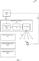
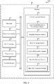
- FIG. 1 shows a block diagram illustrating an example of a VLC system 100, in accordance with various aspects of the present disclosure.
- the VLC system 100 may include a controller 105, a light transmitting device 135, and/or a mobile device 115.
- the VLC system 100 may include any number of controllers 105, mobile devices 115, and/or light transmitting devices 135.
- the controller 105 (or aspects of the controller 105) may be provided by the mobile device 115. In these cases, the mobile device 115 may communicate directly with the light transmitting device 135.
- the light transmitting device 135 may include a communication circuit 130, a driver circuit 140, and/or a light source 145.
- the light source 145 may include one or more light emitting diodes (LEDs) and/or other light emitting elements.
- LEDs light emitting diodes
- a single light source 145 or commonly controlled group of light emitting elements may be provided (e.g., a single light source 145 or commonly controlled group of light emitting elements may be used for ambient illumination and VLC transmissions).
- the light source 145 may be replaced with multiple light sources or separately controlled groups of light emitting elements (e.g ., a first light source may be used for ambient illumination, and a second light source may be used for VLC transmissions).
- the driver circuit 140 or intelligent ballast may be used to drive the light source 145.
- the driver circuit 140 may drive the light source 145 using a current signal and/or a voltage signal.
- some of the intelligence of the driver circuit 140 or intelligent ballast may be moved to the controller 105.
- the controller 105 may take the form of a desktop computer or wall-mounted control pad.
- the functions of the controller 105 may also be provided by the mobile device 115.
- the controller 105 may also be a switch, such as an ON/OFF/dimming switch.
- a user may select or input an illumination factor (e.g., a percentage of dimness) via the controller 105, which illumination factor may be provided by the controller 105 to the light transmitting device 135.
- the controller 105 may provide the illumination factor to a communication circuit 130 of the light transmitting device 135.
- the illumination factor may be provided to the communication circuit 130 over a power line network, a wireless local area network (WLAN; e.g., a Wi-Fi network), and/or a wireless wide area network (WWAN; e.g ., a cellular network such as a Long Term Evolution (LTE) or LTE-Advanced (LTE-A) network).
- WLAN wireless local area network
- WWAN wireless wide area network
- LTE Long Term Evolution
- LTE-A LTE-Advanced
- the controller 105 may also provide the light transmitting device 135 an identifier for transmission using VLC. In some examples, the controller 105 may receive status information from the light transmitting device 135. The status information may include, for example, a light intensity of the light source 145, a thermal performance of the light source 145, and/or an identifier of the light transmitting device 135.
- the light source 145 may provide ambient illumination 125 which may be captured by an image sensor (e.g., a camera) of the mobile device 115.
- the light source 145 may also make VLC transmissions that may be captured by the image sensor of the mobile device 115.
- the illumination and/or VLC transmissions may be used by the mobile device 115 for navigation and/or other purposes.
- the light transmitting device 135 may receive one or more modulation parameters by other entity.
- the modulation parameters may be received by the light transmitting device and stored locally inside the light source's memory (e.g ., electrically erasable programmable read-only memory (EEPROM) or other storage device, and may be loaded into the light source (e.g., a driver circuit) upon receiving a command.
- the modulation parameters may be received from a remote entity such as a mobile device or a sever over a wired or wired link.
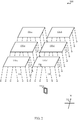
- a diagram 200 illustrates an example of a mobile device 115-a positioned below a number of light transmitting devices 135-a, 135-b, 135-c, 135-d, 135-e, and 135-f.
- the mobile device 115-a may in some cases be an example of the mobile device 115 described with reference to FIG. 1
- the light transmitting devices 135-a, 135-b, 135-c, 135-d, 135-e, and 135-f may in some cases be examples of aspects of the light transmitting device 135 described with reference to FIG. 1 .
- the light transmitting devices 135-a, 135-b, 135-c, 135-d, 135-e, and 135-f may in some examples be overhead light transmitting devices in a building, which overhead light transmitting devices may have fixed locations with respect to a reference (e.g., a global positioning system (GPS) coordinate system and/or building floor plan).
- a reference e.g., a global positioning system (GPS) coordinate system and/or building floor plan.
- the light transmitting devices 135-a, 135-b, 135-c, 135-d, 135-e, and 135-f may also have orientations with respect to a reference (e.g ., a meridian passing through magnetic north 215).
- the image sensor may also or alternatively receive VLC transmissions from one or more of the light transmitting devices 135-a, 135-b, 135-c, 135-d, 135-e, and 135-f.
- the captured image may include an illuminated reference axis, such as the illuminated edge 220 of the light transmitting device 135-f. Such illuminated edges may enable the mobile device to determine its location and/or orientation with reference to one or more of the light transmitting devices 135-a, 135-b, 135-c, 135-d, 135-e, and 135-f.
- the mobile device 115-a may receive, from one or more of the light transmitting devices 135-a, 135-b, 135-c, 135-d, 135-e, and 135-f, VLC transmissions that include identifiers of one or more of the light transmitting devices 135-a, 135-b, 135-c, 135-d, 135-e, and 135-f.
- the location and/or orientation may be used for navigation by the mobile device 115-a.
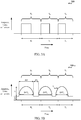
- FIG. 3A illustrates an example of part or all of an identifier encoded in a signal 300 modulated in accordance with the transmission of the identifier from a light source using VLC.
- the signal 300 may variously represent a current signal and/or a voltage signal applied to the light source.
- the signal 300 may alternatively represent a light output of the light source.
- the light source may in some cases be an example of aspects of the light source 145 described with reference to FIG. 1 .
- a basic unit of transmission of the signal 300 is a symbol.
- three symbols e.g ., symbols S 1 , S 2 , and S 3
- Each symbol may be mapped to a unique time interval (e.g ., the symbols S 1 , S 2 , and S 3 may be respectively mapped to the time intervals T 1 , T 2 , and T 3 ).
- the signal 300 may be logically "ON" for a portion of the time interval and logically "OFF" for a portion of the time interval.
- the portion of a time interval in which the signal 300 is logically ON may define a pulse.
- a pulse may alternatively be defined by the portion of a time interval in which the signal 300 is logically OFF.
- the durations of the time intervals T 1 , T 2 , and T 3 to which the symbols S 1 , S 2 , and S 3 are mapped may be based at least in part on a frequency shift keying.
- An identifier may be encoded in the signal 300 as a sequence of the symbols (e.g ., an identifier having an identifier length of four symbols may be defined by the sequence S 1 , S 3 , S 1 , S 2 ).
- a plurality of instances of the identifier may be encoded in the signal 300 and transmitted back-to-back.
- the instances of the identifier may be separated by instances of an interleaving signal, as described with reference to FIG. 4A and/or 4B.
- An identifier length of four symbols and an alphabet size of three symbols are representative only, and in other embodiments, the identifier length may be longer or shorter and the alphabet size may be larger or smaller.
- FIG. 3B illustrates a signal 300-a to which a set of one or more modulation parameters has been applied.
- the signal 300-a may be a modulated version of the signal 300 described with reference to FIG. 3A .
- the set of one or more modulation parameters may include, for example, a pulse duty cycle, a pulse duration, a pulse spacing, a DC bias, a pulse amplitude, and/or a pulse slope.
- the pulse duty cycle, D may be defined as the fraction of time that the signal 300-a spends in a logical ON state relative to a time interval ( e.g ., relative to the time interval T 1 , T 2 , and T 3 ).
- the value of D may range from 0 to 1.
- the pulse duration, PD may be defined as the time that the signal 300-a spends in a logical ON state during a time interval. In some cases, the pulse duration may be selected. Alternatively, the pulse duration may be computed ( e.g ., the pulse duration may be computed as the length of a time interval multiplied by the modulation parameter D). Thus, the pulse duration for time interval T 1 is D*T 1 ; the pulse duration for time interval T 2 is D*T 2 ; and the pulse duration for time interval T 3 is D*T 3 .
- the pulse spacing, PS may be defined as the time that the signal 300-a spends in a logical OFF state during a time interval. In some cases, the pulse spacing may be selected. Alternatively, the pulse spacing may be computed ( e.g ., the pulse spacing may be computed as the length of a time interval multiplied by the factor (1-D), or as the length of a time interval less a pulse duration for the time interval).
- the DC bias, B may be defined as the current level that is nominally transmitted between pulses ( e.g ., during times when the signal 300-a is in a logical OFF state).
- the DC bias may be raised to mitigate or prevent flicker in a light source.
- a signal-to-noise ratio (SNR) of a transmitted instance of an identifier may deteriorate.
- the value of the DC bias may range from zero current to a maximum current level.
- the pulse amplitude, A may be defined as the difference, in amperes, between a peak current and the DC bias.
- the peak current may occur during times when the signal 300-a is in a logical ON state.
- the pulse amplitude may range from 0 to the peak current, depending on the value of the DC bias. In some cases, the amplitude of the signal 300-a during a time interval may not be binary.
- the pulse slope, S may be defined as the slope of a pulse during an OFF-to-ON or ON-to-OFF transition.
- the pulse slope may, in some examples, follow one of a linear function, a piece-wise linear Gaussian function, a raised cosine function, a polynomial function, or an exponential function.
- the DC bias may be raised, the amplitude may be lowered, and/or the pulse slope may be made gentler, to reduce the severity of OFF-to-ON and ON-to-OFF transitions, which transitions may cause a light source to produce excessive heat when the amplitude is too great or the slope is too steep.
- An OFF-to-ON or ON-to-OFF transition having too steep a slope may also give rise to acoustic effects (e.g., high frequency harmonics in inductors and other elements of a driver circuit 140 which generate acoustic waves and, under some conditions, audible signals).
- a gentler slope can reduce these acoustic effects.
- the modulation parameters described with reference to FIG. 3B may in some cases be modified based at least in part on an illumination factor (e.g., a percentage of dimness) associated with a light source.
- the illumination factor may at times be adjusted by a user and/or controller. Thus, one or more of the modulation parameters described with reference to FIG. 3B may be adjusted.
- one or more modulation parameters may be adjusted ( e.g ., modified) so that a total light output of a light source is equal to a predetermined value (e.g ., in lumens or amperes).
- the total light output, V may be based at least in part on an illumination factor (e.g., a percentage of dimness).
- FIG. 4A illustrates an example of part or all of a signal 400 modulated in accordance with the transmission of a plurality of instances of an identifier and a plurality of instances of an interleaving signal.
- the signal 400 may be transmitted from a light source using VLC.
- the signal 400 may variously represent a current signal and/or a voltage signal applied to the light source.
- the signal 400 may alternatively represent a light output of the light source.
- the light source may in some cases be an example of aspects of the light source 145 described with reference to FIG. 1 .
- the interleaving signal ILS t may include a constant current transmitted in accordance with various modulation parameters (e.g ., a pulse duty cycle, a pulse duration, a DC bias, a pulse amplitude, and/or a pulse slope).
- modulation parameters e.g ., a pulse duty cycle, a pulse duration, a DC bias, a pulse amplitude, and/or a pulse slope.
- the set of one or more modulation parameters applied to the signal 400 for transmission of instances of the interleaving signal, ILS t may differ from the set of one or more modulation parameters applied to the signal 400 for transmission of instances of the identifier, C t and C t+1 .
- the set of one or more modulation parameters applied to instances of the identifier and/or the set of one or more modulation parameters applied to instances of the interleaving signal may change over time (e.g ., because of one or more changes in illumination factor, changes in the thermal performance of the light source, changes in the acoustic performance of the light source, changes in the flicker performance of the light source, and/or changes in the SNR of transmitted instances of the identifier).
- FIG. 4B illustrates an example of part or all of a signal 400-a modulated in accordance with the transmission of a plurality of instances of an identifier and a plurality of instances of an interleaving signal.
- the signal 400-a may be transmitted from a light source using VLC.
- the signal 400-a may variously represent a current signal and/or a voltage signal applied to the light source.
- the signal 400-a may alternatively represent a light output of the light source.
- the light source may in some cases be an example of aspects of the light source 145 described with reference to FIG. 1 .
- instances of the identifier may be encoded in the signal 400-a as described with reference to FIG. 3A , and modulated as described with reference to FIG. 3B .
- a plurality of instances of an interleaving signal, ILS t may be interspersed with the instances of the identifier. Transmission of the interleaving signal may help to improve the thermal performance of the light source (e.g ., lower heat dissipation).
- the set of one or more modulation parameters used when transmitting instances of the interleaving signal may be modified to match an average light intensity level of a transmitted instance of the interleaving signal to an average light intensity level of a transmitted instance of the identifier. Such a modification of the set of one or more modulation parameters may mitigate or prevent flicker of the light source.
- the power line interface 512 and/or a wireless local area network (WLAN) interface 514 can be a receiver (e.g ., a power line receiver, or Wi-Fi receiver), a transmitter (e.g., a power line transmitter, or Wi-Fi transmitter), or a transceiver (e.g., a power line transceiver, or Wi-Fi transceiver).
- the light transmitting device 505 may also include alternate and/or additional interfaces modules for communications with other networks such as a WWAN (e.g ., a cellular network such as an LTE/LTE-A), a Bluetooth (BT), and/or a BT Low Energy (BTLE).
- WWAN e.g ., a cellular network such as an LTE/LTE-A
- BT Bluetooth
- BTLE BT Low Energy
- the light transmitting device 505 may include a driver module 532.
- the driver module 532 may generate a current signal, voltage signal, and/or other signal to provide a signal for modulating the light intensity of a light source 145.
- the light transmitting device 505 may also include the light source 145 described with reference to FIG. 1 .
- the WLAN interface 514, power line interface 512, or other additional interfaces may be used to transmit, for example, status information to a user interface provided by a mobile device 115 (e.g., a mobile phone or tablet computer) or controller (e.g., a desktop computer or wall-mounted control pad).
- the status information may in some cases include a light intensity of a light source 145, a thermal performance of the light source 145, and/or an identifier of a light transmitting device 135.
- the set of one or more modulation parameters may include at least one of a pulse duty cycle, a pulse duration, a pulse spacing, a DC bias, a pulse amplitude, and/or a pulse slope.
- the pulse slope may follow a linear function, a piece-wise linear Gaussian function, a raised cosine function, a polynomial function, or an exponential function.
- each of the modulation parameters may be expressed in units of amperes, volts, or lumens.
- the modules of the memory 502 described above may, individually or collectively, be implemented using one or more application-specific integrated circuits (ASICs) adapted to perform some or all of the applicable functions in hardware.
- ASICs application-specific integrated circuits
- the functions may be performed by one or more other processing units (or cores) such as the processor 510, on one or more integrated circuits.
- other types of integrated circuits may be used (e.g. , Structured/Platform ASICs, Field Programmable Gate Arrays (FPGAs), and other Semi-Custom ICs), which may be programmed in any manner known in the art.
- the functions of each module may also be implemented, in whole or in part, with instructions embodied in the memory 502, formatted to be executed by one or more general or application-specific processors such as the processor 510.
- the memory 502-a of the light transmitting device 505-a may store code for instructions (referred to as modules for example) to implement various functions related to VLC communications.
- the memory 502-a may include a dimming signal decoder module 516 and an illumination and communication management module 520-a.
- the illumination and communication management module 520-a may include an illumination factor identification module 540-a, a modulation parameter modifier module 545-a, and/or a VLC transmission management module 550-a. These modules can be executed by the processor 510. In some embodiments, the modules can be executed in a dedicated hardware (e.g., a circuit or circuitry) for performing the functions described herein.
- the illumination and communication management module 520-a may be used to perform various functions related to providing illumination using a light source 145 and/or modulating a light intensity of the light source 145 for VLC.
- the illumination and communication management module 520-a may be an example of the illumination and communication management module 520 described with reference to FIG. 5 .
- the modulation parameter modifier module 545-a may include an illumination factor conversion module 610.
- the illumination factor conversion module 610 may be used to convert an illumination factor identified by the illumination factor identification module 540-a to a total light output.
- the modulation parameter modifier module 545-a may then modify a set of one or more modulation parameters based at least in part on the total light output.
- the total light output may be expressed in lumens.
- the total light output may also or alternatively be expressed as a function of current and/or voltage.
- the modulation parameter modifier module 545-a may be used to alternatively or additionally modify the set of one or more modulation parameters based at least in part on a thermal performance of the light source 145, an acoustic performance of the light source 145, a flicker performance of the light source 145, and/or an SNR of a transmitted instance of the identifier.
- a particular one of the sets may be chosen by the modulation parameter modifier module 545-a at random or based on one or more other factors (e.g ., based on a thermal performance of a light source 145, an acoustic performance of a light source 145, a flicker performance of the light source 145, and/or an SNR of a transmitted instance of the identifier).
- accessing the electronically stored database may include accessing the database locally (e.g., in memory 502-a maintained by the light transmitting device 505-a).
- accessing the electronically stored database may include accessing the database remotely (e.g ., over a network such as a power line network, a Wi-Fi network, or a cellular network).
- the VLC transmission management module 550-a may be an example of the VLC transmission management module 550 described with reference to FIG. 5 .
- the VLC transmission management module 550-a may be used to apply at least one signal in which the identifier is encoded to a light source 145.
- the at least one signal may be applied to the light source 145 in accordance with the set of one or more modulation parameters.
- the at least one signal may in some cases include a current signal and/or a voltage signal and may modulate a light intensity of the light source 145 to transmit the identifier.
- the at least one signal may modulate the light intensity of the light source 145 to transmit a plurality of instances of an identifier.
- an instance of the identifier may be encoded in the at least one signal as a sequence of symbols. In some cases, the sequence of symbols may be based at least in part on a frequency shift keying.
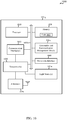
- a block diagram 700 illustrates an example of a light transmitting device 505-b for managing illumination and communication functions of a light transmitting device 135 (e.g., a light transmitting device having aspects of one or more of the light transmitting devices 135 described with reference to FIG. 1 and/or 2).
- the light transmitting device 505-b may be an example of aspects of one or more of the light transmitting devices 135 and/or aspects of one or more of the driver circuits 140 of the light transmitting devices 135.
- the light transmitting device 505-b may also or alternatively be an example of aspects of one or more of the light transmitting devices 505 described with reference to FIG. 5 and/or 6.
- the light transmitting device 505-b may in some cases drive and/or include one or more LEDs.
- the light transmitting device 505-b may include a memory 502-b, a processor 510, a power line interface 512, WLAN interface 514, a driver module 532, and a network interface 555. Each of these components may be in communication with each other, directly or indirectly, over one or more buses 535. In some embodiments, some of the components may be optional.
- the illumination factor identification module 540-b may be an example of the illumination factor identification module 540 described with reference to FIG. 5 and/or 6. In some examples, the illumination factor identification module 540-b may be used to identify an illumination factor associated with a light source 145. The illumination factor may in some cases include a percentage of dimness.
- the modulation parameter modifier module 545-b may be an example of the modulation parameter modifier module 545 described with reference to FIG. 5 and/or 6. In some examples, the modulation parameter modifier module 545-b may include an identifier modulation parameter modifier module 705 and/or an interleaving signal modulation parameter modifier module 710.
- the identifier modulation parameter modifier module 705 may be used to modify a first set of one or more modulation parameters for transmitting an identifier (e.g ., an identifier of a light transmitting device 135) using VLC.
- the first set of one or more modulation parameters may be modified based at least in part on the illumination factor identified by the illumination factor identification module 540-b.
- modifying the first set of one or more modulation parameters may include converting an illumination factor identified by the modulation parameter modifier module 545-b to a total light output, and modifying the set of one or more modulation parameters based at least in part on the total light output.
- the total light output may be expressed in lumens.
- the total light output may also or alternatively be expressed as a function of current and/or voltage.
- the identifier modulation parameter modifier module 705 may be used to alternatively or additionally modify the first set of one or more modulation parameters based at least in part on a thermal performance of the light source 145, an acoustic performance of the light source 145, a flicker performance of the light source 145, and/or an SNR of a transmitted instance of the identifier.
- the first set of one or more modulation parameters may include at least one of a pulse duty cycle, a pulse duration, a pulse spacing, a DC bias, a pulse amplitude, and/or a pulse slope.
- the pulse slope may follow a linear function, a piece-wise linear Gaussian function, a raised cosine function, a polynomial function, or an exponential function.
- each of the modulation parameters may be expressed in units of amperes, volts, or lumens.
- the identifier modulation parameter modifier module 705 may modify the first set of one or more modulation parameters by accessing an electronically stored database that associates illumination factors with modulation parameters. Upon the illumination factor identification module 540-b identifying an illumination factor, the identifier modulation parameter modifier module 705 may retrieve a first set of one or more modulation parameters corresponding to the illumination factor from the database. In some cases, the database may associate an illumination factor with at least two different sets of one or more modulation parameters.
- a particular one of the sets may be chosen by the identifier modulation parameter modifier module 705 at random or based on one or more other factors (e.g., based on a thermal performance of a light source 145, an acoustic performance of a light source 145, a flicker performance of the light source 145, and/or an SNR of a transmitted instance of the identifier).
- accessing the electronically stored database may include accessing the database locally (e.g., in memory 502-b maintained by the light transmitting device 505-b).
- accessing the electronically stored database may include accessing the database remotely (e.g ., over a network such as a power line network, a Wi-Fi network, or a cellular network).
- the electronically stored database may correspond to a building or other venue in which the light transmitting device 505-b is located, or may have a set of entries corresponding to a venue in which the light transmitting device 505-b is located, and the database or set of entries may be uploaded to, downloaded by, or accessed by, the light transmitting device 505-b.
- the interleaving signal modulation parameter modifier module 710 may be used to modify a second set of one or more modulation parameters for transmitting an interleaving signal.
- the second set of one or more modulation parameters may differ from the first set of one or more modulation parameters.
- the interleaving signal may have a constant current. In other configurations, the interleaving signal may include pulses having a fixed frequency.
- the second set of one or more modulation parameters may be modified based at least in part on an identifier, a first set of one or more modulation parameters, an illumination factor, a thermal performance of a light source 145, an acoustic performance of a light source 145, and/or a flicker performance of a light source 145.
- the second set of one or more modulation parameters may be modified to match an average light intensity level of a transmitted instance of the interleaving signal to an average light intensity level of a transmitted instance of the identifier (e.g., to reduce flicker of the light source 145).
- the interleaving signal modulation parameter modifier module 710 may modify the second set of one or more modulation parameters by accessing an electronically stored database that associates sets of modulation parameters for transmitting interleaving signals with sets of modulation parameters for transmitting identifiers.
- the interleaving signal modulation parameter modifier module 710 may use an index associated with the first set of one or more modulation parameter to retrieve, from the same or different database, a second set of one or more modulation parameters for transmitting an interleaving signal.
- the database may associate the index with at least two different sets of one or more modulation parameters.
- a particular one of the sets may be chosen by the interleaving signal modulation parameter modifier module 710 at random or based on one or more other factors (e.g ., based on an identifier, a first set of one or more modulation parameters, an illumination factor, a thermal performance of a light source 145, an acoustic performance of a light source 145, and/or a flicker performance of a light source 145).
- one or more other factors e.g based on an identifier, a first set of one or more modulation parameters, an illumination factor, a thermal performance of a light source 145, an acoustic performance of a light source 145, and/or a flicker performance of a light source 145).
- the modules of the memory 502-b may, individually or collectively, be implemented using one or more ASICs adapted to perform some or all of the applicable functions in hardware. Alternatively, the functions may be performed by one or more other processing units (or cores) such as the processor 510, on one or more integrated circuits. In other examples, other types of integrated circuits may be used (e.g ., Structured/Platform ASICs, FPGAs, and other Semi-Custom ICs), which may be programmed in any manner known in the art.
- the functions of each module may also be implemented, in whole or in part, with instructions embodied in the memory 502-b, formatted to be executed by one or more general or application-specific processors such as the processor 510.
- the power line interface 812 can be a receiver ( e.g ., a power line receiver), a transmitter (e.g., a power line transmitter), or a transceiver (e.g., a power line transceiver).
- the WLAN interface 814 can be a receiver ( e.g ., a WLAN receiver), a transmitter (e.g., a WLAN transmitter), or a transceiver (e.g., a WLAN transceiver).
- the controller 805 may also include alternate and/or additional interfaces modules for communications with other networks such as a WWAN (e.g ., a cellular network such as an LTE/LTE-A), a Bluetooth (BT), and/or a BT Low Energy (BTLE).
- WWAN e.g ., a cellular network such as an LTE/LTE-A
- BT Bluetooth
- BTLE BT Low Energy
- the transceiver(s) 830 may be used, for example, to transmit identifiers to each of a number of light transmitting devices 135.
- the transceiver(s) 830 may also be used, for example, to transmit the same or different illumination factors to the light transmitting devices 135, to transmit other commands and/or control signals to the light transmitting devices 135, or to transmit status information to one or more mobile devices 115.
- the identifier length, N, and alphabet size, N_s may be selected such that a plurality of identifiers equal to or greater than the number, K, of light transmitting devices 135 in the plurality of light transmitting devices 135 is expected (or ensured) to remain following the identifier removal operation(s) performed by the identifier removal module 860 (e.g., such that N_s ⁇ N > K).
- the cyclic shift identifier module 855 may be used to determine a plurality of cyclic shifts for each identifier of the plurality of identifiers.
- the identifier removal module 860 may be used to remove identifiers from the plurality of identifiers that match the identified cyclic shifts.
- the mobile device 115-b may include memory 905, a general purpose processor 910, and a digital signal processor (DSP) 920, at least one wireless transceiver (represented by wireless transceiver(s) 930), one or more antennas 940, image sensor(s) 950, communications interface(s) 960, and/or a Global Navigation Satellite System (GNSS) receiver 970.
- DSP digital signal processor
- Each of these components may be in communication with each other, directly or indirectly, over one or more buses 935. In some embodiments, some of the components may be optional.
- the general purpose processor 910 or DSP 920 may include an intelligent hardware device, e.g., a CPU, such as an ARM® based processor or those made by Intel® Corporation or AMD®, a microcontroller, an ASIC, etc.
- the general purpose processor 910, and/or DSP 920 may process information received via the wireless transceiver(s) 930 or the GNSS receiver 970 of the mobile device 115-b, as well as information to be sent via the wireless transceiver(s) 930 of the mobile device 115-b.
- the processor 910, and/or DSP 920 may handle, alone or in connection with the image sensor(s) 950, the GNSS receiver 970, and memory 905, various aspects pertaining to navigation based at least in part on VLC transmissions received from a number of light transmitting devices 135.
- the wireless transceiver(s) 930 may include a modem configured to modulate packets and provide the modulated packets to the antenna(s) 940 for transmission, and to demodulate packets received from the antenna(s) 940.
- the wireless transceiver(s) 930 may in some cases be implemented as one or more separate transmitters and a receivers.
- the wireless transceiver(s) 930 may be configured to communicate uni-directionally or bi-directionally, via the antenna(s) 940, with one or more other entities, such as an access point or base station of a wireless communications network, one or more controllers 105, 805 for a number of light transmitting devices 135, one or more other mobile devices 115, and/or a number of light transmitting devices 135. While the mobile device 115-b includes only two antennas 940 in FIG. 9 , there may be embodiments in which the mobile device 115-b may include multiple antennas ( e.g ., antenna array).
- the image sensor(s) 950 may in some cases include a complimentary metal-oxide semiconductor (CMOS) image sensor, and in some cases may be configured as a rolling shutter image sensor.
- CMOS complimentary metal-oxide semiconductor
- the image sensor(s) 950 may be used to capture images of light transmitting devices 135 and/or VLC transmissions from light transmitting devices 135.
- the memory 905 may also store processor-executable code for instructions to implement a navigation function based on VLC transmissions 934, 974 received by the wireless transceiver(s) 930 and/or the GNSS receiver 970 from a number of light transmitting devices 135.
- Each of the VLC transmissions may include an identifier of a light transmitting device 135.
- the identifier(s) may be used by the mobile device 115-b to determine a location of each light transmitting device 135 for which an identifier is received. Based at least in part on the locations of one or more light transmitting devices 135 with respect to the mobile device 115-b, the mobile device 115-b may determine a location and/or orientation of the mobile device 115-b.
- the light transmitting device 135-g may include a processor 1010, a memory 1020, an illumination and communication management module 520-c, one or more transceiver(s)1030, power line interface 1040, communication interface(s) 1060, one or more antenna(s) 1070, and/or one or more light sources (represented by light source(s) 145-a). Each of these components may be in communication with each other, directly or indirectly, over one or more buses 1035.
- part or all of the processor 1010, the memory 1020, the illumination and communication management module 520-c, and/or the transceiver(s) 1030 may function as a driver circuit 140 or intelligent ballast for the light source(s) 145-a.
- the light source(s) 145-a may include one or more LEDs.
- the transceiver(s) 1130 may include a modem configured to modulate packets and provide the modulated packets to the antenna(s) 1140 and/or a power line interface 1170 for transmission, and to demodulate packets received from the antenna(s) 1140 and/or a power line interface 1170.
- the transceiver(s) 1130 may be configured to communicate uni-directionally or bi-directionally, via the antenna(s) 1140 and/or a power line interface 1170, with one or more other devices, such as one or more other controllers 105, one or more mobile devices 115, and/or one or more light transmitting devices 135.
- the method 1200 may include receiving input identifying an illumination factor associated with a light source 145.
- the light source 145 may in some cases be or include one or more LEDs.
- the illumination factor may in some cases include a percentage of dimness.
- the input may be received, for example, from a light switch located at the light source or on a wall, from a controller 105 (e.g., a desktop computer or wall-mounted controller), or from a mobile device 115 (e.g., a mobile phone or tablet computer).
- the operation(s) at block 1205 may be performed and/or managed using the illumination and communication management module 520 described with reference to FIG. 5 , 6 , 7 , and/or 10, and/or the illumination factor identification module 540 described with reference to FIG. 5 , 6 , and/or 7.
- accessing the electronically stored database may include accessing the database locally (e.g., in memory maintained at a light transmitting device 135, or as part of a driver circuit 140 for a light source 145 of the light transmitting device 135). In other examples, accessing the electronically stored database may include accessing the database remotely ( e.g ., over a network such as a power line network, a Wi-Fi network, or a cellular network). In some examples, the electronically stored database may correspond to a building or other venue, or may have a set of entries corresponding to a venue, and the database or set of entries may be uploaded to, downloaded by, or accessed by, a driver circuit 140 of each of one or more light transmitting devices 135 in the venue.
- aspects of the methods 1200 and 1300 described with reference to FIGS. 12 and 13 may be combined.
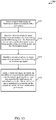
- FIG. 14 is a flow chart illustrating a method 1400 for generating an identifier (e.g., an identifier of a light transmitting device 135) to transmit using VLC.
- an identifier e.g., an identifier of a light transmitting device 135
- the method 1400 is described below with reference to aspects of one or more of the controllers 105 and/or 805 described with reference to FIG. 1 , 8 , and/or 11.
- the VLC management module 820 described with reference to FIG. 8 and/or 11 may execute one or more sets of codes to control the functional elements of a controller 105, 805 to perform the functions described below.
- the method 1400 may include storing the generated identifiers.
- the operation(s) at block 1415 may be performed and/or managed using the memory 802 and/or 1120 described with reference to FIG. 8 and/or 11, and/or the identifier storage module 850 of the memory 802 described with reference to FIG. 8 .
- the method 1400 may include identifying a plurality of cyclic shifts for each identifier of the plurality of identifiers.
- the operation(s) at block 1420 may be performed and/or managed using the processor 810 and/or 1110 described with reference to FIG. 8 and/or 11, in conjunction with the cyclic shift identifier module 855 of the memory 802 described with reference to FIG. 8 .
- the method 1400 may include removing identifiers from the plurality of identifiers that match the identified cyclic shifts.
- the operation(s) at block 1425 may be performed and/or managed using the processor 810 and/or 1110 described with reference to FIG. 8 and/or 11, in conjunction with the identifier removal module 860 of the memory 802 described with reference to FIG. 8 .
- the removal of identifiers that are cyclic shifts of other identifiers can speed the rate at which an identifier received at a mobile device 115 and/or other device by means of a VLC transmission is decoded. For example, when an identifier is received at the mobile device 115 and/or other device using a rolling shutter image sensor, a large number of symbol and/or bit erasures may occur. That is, the mobile device 115 and/or other device may only receive some of the symbols and/or bits of an identifier.
- FIG. 15 is a flow chart illustrating a method 1500 for receiving an identifier (e.g., an identifier of a light transmitting device 135) using VLC, in accordance with various aspects of the present disclosure.
- an identifier e.g., an identifier of a light transmitting device 135
- VLC virtualized liquid crystal display
- the method 1500 may include receiving at least one signal using VLC, the at least one signal comprising an identifier of the light transmitting device and the at least one signal being generated at the light transmitting device in accordance with a first set of one or more modulation parameters.
- the first set of one or more modulation parameters may be modified based at least in part on the illumination factor.
- the operation(s) at block 1510 may be performed and/or managed using the image sensor 950 described with reference to FIG. 9 and/or the sensor/camera block 1770 in conjunction with transceiver(s) 930 described with reference to FIG. 9 and/or 17, and/or the transceiver(s) described with reference to FIG. 10 .
- the second set of one or more modulation parameters may be modified to match an average light intensity level of a transmitted instance of the interleaving signal to an average light intensity level of a transmitted instance of the identifier.
- the interleaving signal may be a constant current or pulses having a fixed frequency.
- the method 1500 may include decoding the at least one signal to obtain the identifier.
- the operation(s) at block 1515 may be performed and/or managed using the processor 910 and/or 920 described with reference to FIG. 9 , the signal decoder block 1750 and/or the identifier decoder block 1752 described with reference to FIG. 17 .
- the method 1500 may be used for wireless communication. It should be noted that the method 1500 is just one implementation and that the operations of the method 1500 may be rearranged or otherwise modified such that other implementations are possible.
- FIG. 16 shows a diagram 1600 of a light transmitting device 505-c in which examples of modules and components are represented by functionality blocks, in accordance with various aspects of present disclosure.
- Each of the functionality blocks may be used to perform various functions of light transmitting devices 135 and/or light transmitting device 505 described with reference to FIG. 1 , 2 , 5 , 6 , 7 , and/or 10.
- the light transmitting device 505-c may include an illumination and communication management block 1620, a receiver block 1610, and an output block 1630.
- the illumination and communication management block 1620 may include an illumination identification block/input processing block 1640, a modulation parameter modifier block 1650, and a VLC transmission management block 1660.
- the receiver block 1610 may include a power line receiver block 1612, which may perform functions related to transmissions via the power line interface described with reference to FIG. 5 , 6 , or 7 and the WLAN receiver block 1614, which may perform functions related to transmissions via the WLAN interface described with reference to FIG. 5 , 6 , or 7 .
- the dimming signal decoder block 1616 may perform the functions of the dimming signal decoder module 516 described with reference to FIG. 5 , 6 , or 7 .
- the driver block 1632 may perform the functions of the driver module 532 described with reference to FIG. 5 , 6 , or 7 and the transmitter block 1634 may perform the functions of the power line interface 512, the WLAN interface described with reference to FIG. 5 , 6 , or 7 .
- the driver block 1632 and the transmitter block 1634 may be referred to as the output block 1630 in some example.
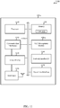
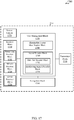
- FIG. 17 shows a diagram 1700 of a mobile device 115-c in which examples of modules and components are represented by functionality blocks, in accordance with various aspects of present disclosure.
- the mobile device 115-c may include a VLC management block 1720, a receiver block 1710, and a transmitter block 1730.
- the VLC management block 1720 may include an illumination factor identification block 1740, a signal decoder block 1750, and a navigation block 1760. Each of these blocks may be in communication with each other and performs functions related to the mobile device 115 described in FIG. 1 , 2 , and/or 9.
- the illumination factor identification block 1740 may be used to identify an illumination factor associated with a light source 145 to be provided to light transmitting devices 135 of FIG 1 and/or FIG. 2 .
- the light source 145 may in some cases be or include one or more LEDs.
- the illumination factor may in some cases include a percentage of dimness.
- the signal decoder block 1750 may be used to decode one or more signals received using VLC.
- the signal may be an identifier of the light transmitting device.
- the mobile device 115-c may receive at least one signal comprising the identifier and the identifier decoder block 1752 of the mobile device 115-c may be used to decode the at least one signal to obtain the identifier.
- the mobile device 115-c may receive an interleaving signal, where a plurality of instances of the identifier is interspersed with a plurality of instances of the interleaving signal. In these cases, the interleaving signal decoder block 1754 may be used to decode the interleaving signal to obtain the identifier.
- the sensor/camera block 1770 may in some cases include a CMOS image sensor, and in some cases may be configured as a rolling shutter image sensor.
- the sensor/camera block 1770 may be used to capture images of light transmitting devices 135 and/or VLC transmissions from light transmitting devices 135.
- the navigation block 1760 may be used to implement a navigation function based on VLC transmissions received from a number of light transmitting devices 135. Each of the VLC transmissions may include an identifier of a light transmitting device 135. The identifier(s) may be used by the navigation block 1760 to determine a location of each light transmitting device 135 for which an identifier is received. Based at least in part on the locations of one or more light transmitting devices 135 with respect to the mobile device 115-c, the navigation block 1760 may determine a location and/or orientation of the mobile device 115-c. By way of example, the navigation block 1760 may be a component of the mobile device 115-c in communication with some or all of the other components of the mobile device 115-c over one or more buses. Alternatively, functionality of the navigation block 1760 may be implemented as a computer program product and/or as one or more controller elements of the processor such as the processors 910, 920 described with reference to FIG. 9 .
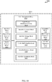
- FIG. 18 shows a diagram 1800 of a controller 105-b in which examples of modules and components are represented by functionality blocks, in accordance with various aspects of present disclosure.
- the controller 105-b may include a VLC management block 1820, a receiver block 1810, and a transmitter block 1830.
- the VLC management block 1820 may include a light transmitting device identification block 1840, an identifier generator block 1845, an identifier storage block 1850, a cyclic shift identifier block 1855, an identifier removal block 1860, and/or an identifier assignment block 1865.
- the light transmitting device identification block 1840 may perform the functions of the light transmitting device identification module 840 described with respect to FIG. 8
- the identifier generator block 1845 may perform the functions of the identifier generator module 845 described with respect to FIG. 8
- the identifier storage block 1850 may perform the functions of the identifier storage module 850 described with respect to FIG. 8
- the cyclic shift identifier block 1855 may perform the functions of the cyclic shift identifier module 855 described with respect to FIG. 8
- the identifier removal block 1860 may perform the functions of the identifier removal module 860 described with respect to FIG.
- the receiver block 1810 and the transmitter block 1830 may each include a power line block 1812, 1832 and a WLAN block 1814, 1834, and each may perform the functions of the power line interface 812 and the WLAN interface 814 to receive or transmit transmissions via a power line and WLAN.
- a CDMA system may implement a radio technology such as CDMA2000, Universal Terrestrial Radio Access (UTRA), etc.
- CDMA2000 covers IS-2000, IS-95, and IS-856 standards.
- IS-2000 Releases 0 and A are commonly referred to as CDMA2000 IX, IX, etc.
- IS-856 (TIA-856) is commonly referred to as CDMA2000 1xEV-DO, High Rate Packet Data (HRPD), etc.
- UTRA, E-UTRA, UMTS, LTE, LTE-A, and GSM are described in documents from an organization named "3rd Generation Partnership Project” (3GPP).
- CDMA2000 and UMB are described in documents from an organization named “3rd Generation Partnership Project 2" (3GPP2).
- the techniques described herein may be used for the systems and radio technologies mentioned above as well as other systems and radio technologies.
- Information and signals may be represented using any of a variety of different technologies and techniques.
- data, instructions, commands, information, signals, bits, symbols, and chips that may be referenced throughout the above description may be represented by voltages, currents, electromagnetic waves, magnetic fields or particles, optical fields or particles, or any combination thereof.
- ASIC application specific integrated circuit
- DSP digital signal processor
- a general-purpose processor may be a microprocessor, any conventional processor, controller, microcontroller, state machine, or combination thereof.
- a processor may also be implemented as a combination of computing devices, e.g., a combination of a DSP and a microprocessor, multiple microprocessors, one or more microprocessors in conjunction with a DSP core, or any other such configuration.
- the functions described herein may be implemented in hardware, software executed by a processor, firmware, or any combination thereof. If implemented in software executed by a processor, the functions may be stored on or transmitted over as one or more instructions or code on a computer-readable medium. Other examples and implementations are within the scope of the disclosure and appended claims. For example, due to the nature of software, functions described above can be implemented using software executed by a processor, hardware, firmware, hardwiring, or combinations of any of these. Features implementing functions may also be physically located at various positions, including being distributed such that portions of functions are implemented at different physical locations.
- Computer-readable media includes both computer storage media and communication media including any medium that facilitates transfer of a computer program from one place to another.
- a storage medium may be any available medium that can be accessed by a general purpose or special purpose computer.
- computer-readable media can comprise RAM, ROM, EEPROM, compact disc (CD)-ROM or other optical disk storage, magnetic disk storage or other magnetic storage devices, or any other medium that can be used to carry or store desired program code means in the form of instructions or data structures and that can be accessed by a general-purpose or special-purpose computer, or a general-purpose or special-purpose processor.
- any connection is properly termed a computer-readable medium.
- Disk and disc include CD, laser disc, optical disc, digital versatile disc (DVD), floppy disk and Blu-ray disc where disks usually reproduce data magnetically, while discs reproduce data optically with lasers. Combinations of the above are also included within the scope of computer-readable media.
Landscapes
- Engineering & Computer Science (AREA)
- Computer Networks & Wireless Communication (AREA)
- Signal Processing (AREA)
- Physics & Mathematics (AREA)
- Electromagnetism (AREA)
- Optical Communication System (AREA)
- Circuit Arrangement For Electric Light Sources In General (AREA)
Priority Applications (1)
| Application Number | Priority Date | Filing Date | Title |
|---|---|---|---|
| EP18165987.1A EP3364566B1 (en) | 2014-06-18 | 2015-06-18 | Transmission of identifiers using visible light communication |
Applications Claiming Priority (3)
| Application Number | Priority Date | Filing Date | Title |
|---|---|---|---|
| US201462013885P | 2014-06-18 | 2014-06-18 | |
| US14/742,185 US10009100B2 (en) | 2014-06-18 | 2015-06-17 | Transmission of identifiers using visible light communication |
| PCT/US2015/036385 WO2015195885A2 (en) | 2014-06-18 | 2015-06-18 | Transmission of identifiers using visible light communication |
Related Child Applications (1)
| Application Number | Title | Priority Date | Filing Date |
|---|---|---|---|
| EP18165987.1A Division EP3364566B1 (en) | 2014-06-18 | 2015-06-18 | Transmission of identifiers using visible light communication |
Publications (2)
| Publication Number | Publication Date |
|---|---|
| EP3158664A2 EP3158664A2 (en) | 2017-04-26 |
| EP3158664B1 true EP3158664B1 (en) | 2018-04-11 |
Family
ID=54870604
Family Applications (2)
| Application Number | Title | Priority Date | Filing Date |
|---|---|---|---|
| EP15733598.5A Active EP3158664B1 (en) | 2014-06-18 | 2015-06-18 | Transmission of identifiers using visible light communication |
| EP18165987.1A Active EP3364566B1 (en) | 2014-06-18 | 2015-06-18 | Transmission of identifiers using visible light communication |
Family Applications After (1)
| Application Number | Title | Priority Date | Filing Date |
|---|---|---|---|
| EP18165987.1A Active EP3364566B1 (en) | 2014-06-18 | 2015-06-18 | Transmission of identifiers using visible light communication |
Country Status (8)
| Country | Link |
|---|---|
| US (2) | US10009100B2 (enExample) |
| EP (2) | EP3158664B1 (enExample) |
| JP (1) | JP2017525207A (enExample) |
| KR (1) | KR20170018335A (enExample) |
| CN (1) | CN106464368B (enExample) |
| ES (2) | ES2870979T3 (enExample) |
| HU (1) | HUE037521T2 (enExample) |
| WO (1) | WO2015195885A2 (enExample) |
Families Citing this family (54)
| Publication number | Priority date | Publication date | Assignee | Title |
|---|---|---|---|---|
| US10009099B2 (en) * | 2014-03-29 | 2018-06-26 | Intel Corporation | Techniques for communication with body-carried devices |
| US10009100B2 (en) | 2014-06-18 | 2018-06-26 | Qualcomm Incorporated | Transmission of identifiers using visible light communication |
| JP6434724B2 (ja) * | 2014-07-01 | 2018-12-05 | パナソニック インテレクチュアル プロパティ コーポレーション オブ アメリカPanasonic Intellectual Property Corporation of America | 情報通信方法 |
| US9749782B2 (en) * | 2014-07-31 | 2017-08-29 | Qualcomm Incorporated | Light fixture commissioning using encoded light signals |
| KR101525004B1 (ko) * | 2014-09-15 | 2015-06-04 | (주)유양디앤유 | 가시광 통신을 이용한 전시장 내 관람객 경로 안내 방법 및 장치 |
| KR101481378B1 (ko) * | 2014-09-15 | 2015-01-15 | (주)유양디앤유 | 가시광 통신을 이용한 지하철역 내 시각 장애인 경로 안내 방법 및 장치 |
| US10020881B2 (en) * | 2014-11-25 | 2018-07-10 | Qualcomm Incorporated | Method and apparatus for transmitting secure VLC identifiers |
| JP6425173B2 (ja) * | 2015-03-06 | 2018-11-21 | パナソニックIpマネジメント株式会社 | 照明装置及び照明システム |
| JP2016167385A (ja) * | 2015-03-09 | 2016-09-15 | パナソニックIpマネジメント株式会社 | 携帯端末及び機器制御システム |
| JP6504448B2 (ja) * | 2015-06-01 | 2019-04-24 | パナソニックIpマネジメント株式会社 | 変調装置および照明器具 |
| JP6593681B2 (ja) | 2015-06-02 | 2019-10-23 | パナソニックIpマネジメント株式会社 | 変調装置、発光装置及び発光システム |
| US9699855B2 (en) * | 2015-09-01 | 2017-07-04 | Aleddra Inc. | Add-on IPS controller for LED lighting device |
| JP6587056B2 (ja) * | 2015-09-02 | 2019-10-09 | パナソニックIpマネジメント株式会社 | 携帯機器、発信装置及び案内システム |
| JP6551785B2 (ja) * | 2015-09-10 | 2019-07-31 | パナソニックIpマネジメント株式会社 | 情報提示方法、サーバ、及び、情報提示システム |
| US9949347B2 (en) | 2015-09-25 | 2018-04-17 | General Electric Company | System and processes for commissioning indoor industrial lighting |
| US9974146B2 (en) * | 2015-09-25 | 2018-05-15 | General Electric Company | Commissioning method of lighting control system using visual light communication |
| ES2795925T3 (es) * | 2015-11-26 | 2020-11-25 | Signify Holding Bv | Asignación de canal de luz dinámica |
| US10449572B2 (en) | 2015-12-16 | 2019-10-22 | Waste Repurposing International, Inc. | Household hazardous waste recovery |
| US9707595B2 (en) * | 2015-12-16 | 2017-07-18 | Waste Repurposing International, Inc. | Household hazardous waste recovery |
| US9712234B1 (en) * | 2015-12-28 | 2017-07-18 | Wisconsin Alumni Research Foundation | Location aware communication system using visible light transmission |
| JP6518793B2 (ja) * | 2016-01-04 | 2019-05-22 | 日立オートモティブシステムズ株式会社 | 電力線通信装置、および電力線通信装置を備えた電子制御装置 |
| WO2017119619A1 (ko) * | 2016-01-08 | 2017-07-13 | 서울과학기술대학교 산학협력단 | 디스플레이의 표출 컬러 및 패턴 형태를 이용한 가시광 통신 방법 |
| US20170244482A1 (en) * | 2016-02-24 | 2017-08-24 | Qualcomm Incorporated | Light-based communication processing |
| NL2017308B1 (en) * | 2016-08-11 | 2018-02-16 | Eldolab Holding Bv | Method of light unit replacement |
| US9961662B2 (en) * | 2016-09-01 | 2018-05-01 | Honeywell International Inc. | System for tracking assets |
| US10158425B2 (en) * | 2016-09-14 | 2018-12-18 | Qualcomm Incorporated | Methods and systems for adjusting an orientation of a light sensor |
| DE102016219200A1 (de) * | 2016-10-04 | 2018-04-05 | Tridonic Gmbh & Co Kg | Integrierte Anordnung modulierbarer Lichtpunkte für Kommunikation mittels sichtbarem Licht |
| CN107918306B (zh) * | 2016-10-11 | 2024-01-05 | 海湾安全技术有限公司 | 现场设备的物理位置信息确定 |
| US10771156B2 (en) * | 2016-11-10 | 2020-09-08 | Signify Holding B.V. | Systems and methods for improved optical wireless communications based on mobility patterns |
| US10135529B2 (en) * | 2017-01-16 | 2018-11-20 | GM Global Technology Operations LLC | Automotive light based communication system for user equipment |
| WO2018137236A1 (zh) * | 2017-01-26 | 2018-08-02 | 华为技术有限公司 | 相机通信的方法、装置和设备 |
| JP6799819B2 (ja) * | 2017-01-30 | 2020-12-16 | パナソニックIpマネジメント株式会社 | 点灯装置、照明器具及び看板 |
| NL2019630B1 (en) * | 2017-09-26 | 2019-04-03 | Eldolab Holding Bv | LED driver for VLC |
| US10128941B2 (en) | 2017-04-12 | 2018-11-13 | Futurewei Technologies, Inc. | Dimming control for orthogonal frequency division multiplexing-based visible light communication |
| CN108734945B (zh) * | 2017-04-20 | 2020-10-30 | 台达电子工业股份有限公司 | 通过光源实现的感测器指令传输与配置方法 |
| EP3619775B1 (en) * | 2017-05-02 | 2023-03-29 | Asco, L.P. | Modular electrical fieldbus system with stacked interconnected functional components |
| JP2018206485A (ja) * | 2017-05-30 | 2018-12-27 | パナソニックIpマネジメント株式会社 | 制御回路、照明装置、照明器具及び看板 |
| JP2019012329A (ja) * | 2017-06-29 | 2019-01-24 | パナソニックIpマネジメント株式会社 | 光id送信装置、及び、光id通信システム |
| CN110914701A (zh) * | 2017-07-26 | 2020-03-24 | 昕诺飞控股有限公司 | 用于经由光源传送设备的存在的系统 |
| NL2019673B1 (en) | 2017-10-05 | 2019-04-15 | Eldolab Holding Bv | System and method for operating at least one LED unit of a lighting grid comprising a plurality of LED units |
| US10117316B1 (en) * | 2017-10-13 | 2018-10-30 | Osram Sylvania Inc. | Rotating identifications in light-based positioning systems |
| JP7395354B2 (ja) | 2017-12-19 | 2023-12-11 | パナソニック インテレクチュアル プロパティ コーポレーション オブ アメリカ | 受信方法および受信装置 |
| FR3083942A1 (fr) * | 2018-07-11 | 2020-01-17 | Valeo Vision | Systeme de communication optique sans fil pour vehicule |
| US10778330B1 (en) * | 2018-08-03 | 2020-09-15 | Synapse Wireless, Inc. | Identification of orphaned light sources in wireless lighting networks |
| JP7194846B2 (ja) * | 2019-04-18 | 2022-12-22 | シグニファイ ホールディング ビー ヴィ | 照明デバイス |
| CN112152715B (zh) * | 2019-06-28 | 2022-08-02 | Oppo广东移动通信有限公司 | 通信控制方法、装置、存储介质及电子设备 |
| JP7294428B2 (ja) * | 2019-08-07 | 2023-06-20 | 日本電信電話株式会社 | 無線通信システム、無線端末装置、無線基地局装置及び無線通信方法 |
| US11328564B2 (en) | 2019-08-31 | 2022-05-10 | Appleton Grp Llc | Event indications of hazardous environment luminaires using visual sequences |
| US11232684B2 (en) | 2019-09-09 | 2022-01-25 | Appleton Grp Llc | Smart luminaire group control using intragroup communication |
| US11219112B2 (en) | 2019-09-09 | 2022-01-04 | Appleton Grp Llc | Connected controls infrastructure |
| US11343898B2 (en) | 2019-09-20 | 2022-05-24 | Appleton Grp Llc | Smart dimming and sensor failure detection as part of built in daylight harvesting inside the luminaire |
| US11387902B2 (en) | 2020-04-10 | 2022-07-12 | The Boeing Company | Wireless control of a passenger service unit using a personal device of a passenger |
| US11176810B2 (en) * | 2020-04-10 | 2021-11-16 | The Boeing Company | Wireless control of a passenger service unit |
| WO2022049046A1 (en) * | 2020-09-01 | 2022-03-10 | Signify Holding B.V. | Performing visible light communication with a lighting unit |
Family Cites Families (26)
| Publication number | Priority date | Publication date | Assignee | Title |
|---|---|---|---|---|
| US8093817B2 (en) * | 2005-04-22 | 2012-01-10 | Koninklijke Philips Electronics N.V. | Method and system for lighting control |
| WO2008037114A1 (en) * | 2006-09-25 | 2008-04-03 | Huawei Technologies Co., Ltd. | Information carrying synchronization code and method for frame timing synchronization |
| JP5285301B2 (ja) * | 2008-02-26 | 2013-09-11 | パナソニック株式会社 | 光伝送システム |
| EP2101424B1 (de) * | 2008-03-10 | 2013-02-27 | Siemens Aktiengesellschaft | Verfahren und Vorrichtung zur optischen Übertragung von Daten |
| EP2274958B1 (en) * | 2008-05-06 | 2017-09-13 | Philips Lighting Holding B.V. | Illumination system and method for processing light |
| JP2010034952A (ja) * | 2008-07-30 | 2010-02-12 | Toshiba Corp | 可視光通信システム及び可視光通信方法 |
| US8107825B2 (en) * | 2009-05-08 | 2012-01-31 | Samsung Electronics Co., Ltd. | Apparatus and method for support of dimming in visible light communication |
| EP2443911B1 (en) * | 2009-06-19 | 2015-08-12 | Koninklijke Philips N.V. | Illumination system and method with improved snr |
| US8620154B2 (en) * | 2009-07-31 | 2013-12-31 | Samsung Electronics Co., Ltd. | Methods and apparatus for fast and energy-efficient light recovery in a visible light communication (VLC) system |
| RU2548900C2 (ru) | 2009-10-28 | 2015-04-20 | Конинклейке Филипс Электроникс Н.В. | Ввод в действие источников кодированного света |
| KR101654934B1 (ko) * | 2009-10-31 | 2016-09-23 | 삼성전자주식회사 | 가시광 통신 방법 및 장치 |
| RU2557802C2 (ru) * | 2010-01-15 | 2015-07-27 | Конинклейке Филипс Электроникс Н.В. | Детектирование данных для передачи данных в видимом свете, используя датчик обычной камеры |
| WO2012153220A1 (en) | 2011-05-06 | 2012-11-15 | Koninklijke Philips Electronics N.V. | Lighting device and receiver |
| US9418115B2 (en) * | 2011-07-26 | 2016-08-16 | Abl Ip Holding Llc | Location-based mobile services and applications |
| US9444547B2 (en) * | 2011-07-26 | 2016-09-13 | Abl Ip Holding Llc | Self-identifying one-way authentication method using optical signals |
| US8930064B2 (en) * | 2011-10-27 | 2015-01-06 | Snap-On Incorporated | Method and system for automated and manual data capture configuration |
| WO2013108167A1 (en) * | 2012-01-17 | 2013-07-25 | Koninklijke Philips N.V. | Modulation of light emitted by a lighting device, using plurality of different modulation periods |
| US8873691B2 (en) | 2012-09-10 | 2014-10-28 | Broadcom Corporation | Generating codes for sync words to avoid cyclic collision |
| US9560284B2 (en) * | 2012-12-27 | 2017-01-31 | Panasonic Intellectual Property Corporation Of America | Information communication method for obtaining information specified by striped pattern of bright lines |
| CN103383446B (zh) * | 2013-04-09 | 2017-07-07 | 北京半导体照明科技促进中心 | 基于可见光的室内定位方法、装置和系统以及光源 |
| CN103795487B (zh) * | 2013-09-30 | 2015-03-11 | 深圳光启创新技术有限公司 | 可见光信号发送、接收处理方法、发射端、接收端及系统 |
| US9571312B2 (en) * | 2013-11-26 | 2017-02-14 | University Of Virginia Patent Foundation | Expurgated pulse position modulation for communication |
| US10237953B2 (en) * | 2014-03-25 | 2019-03-19 | Osram Sylvania Inc. | Identifying and controlling light-based communication (LCom)-enabled luminaires |
| US9780873B2 (en) * | 2014-03-25 | 2017-10-03 | Osram Sylvania Inc. | Light-based communication transmission protocol |
| EP3143759A1 (en) * | 2014-05-12 | 2017-03-22 | Philips Lighting Holding B.V. | Verification of images captured using a timestamp decoded from illumination from a modulated light source |
| US10009100B2 (en) | 2014-06-18 | 2018-06-26 | Qualcomm Incorporated | Transmission of identifiers using visible light communication |
-
2015
- 2015-06-17 US US14/742,185 patent/US10009100B2/en active Active
- 2015-06-18 EP EP15733598.5A patent/EP3158664B1/en active Active
- 2015-06-18 JP JP2016573471A patent/JP2017525207A/ja active Pending
- 2015-06-18 EP EP18165987.1A patent/EP3364566B1/en active Active
- 2015-06-18 ES ES18165987T patent/ES2870979T3/es active Active
- 2015-06-18 WO PCT/US2015/036385 patent/WO2015195885A2/en not_active Ceased
- 2015-06-18 CN CN201580031593.0A patent/CN106464368B/zh active Active
- 2015-06-18 HU HUE15733598A patent/HUE037521T2/hu unknown
- 2015-06-18 KR KR1020167035241A patent/KR20170018335A/ko not_active Withdrawn
- 2015-06-18 ES ES15733598.5T patent/ES2668953T3/es active Active
-
2018
- 2018-05-23 US US15/987,692 patent/US10382129B2/en active Active
Also Published As
| Publication number | Publication date |
|---|---|
| EP3158664A2 (en) | 2017-04-26 |
| WO2015195885A3 (en) | 2016-02-25 |
| US20180269970A1 (en) | 2018-09-20 |
| US10009100B2 (en) | 2018-06-26 |
| ES2668953T3 (es) | 2018-05-23 |
| US20150372753A1 (en) | 2015-12-24 |
| CN106464368A (zh) | 2017-02-22 |
| CN106464368B (zh) | 2019-05-28 |
| EP3364566A1 (en) | 2018-08-22 |
| US10382129B2 (en) | 2019-08-13 |
| EP3364566B1 (en) | 2021-04-21 |
| JP2017525207A (ja) | 2017-08-31 |
| ES2870979T3 (es) | 2021-10-28 |
| KR20170018335A (ko) | 2017-02-17 |
| WO2015195885A2 (en) | 2015-12-23 |
| HUE037521T2 (hu) | 2018-09-28 |
Similar Documents
| Publication | Publication Date | Title |
|---|---|---|
| EP3158664B1 (en) | Transmission of identifiers using visible light communication | |
| KR101827685B1 (ko) | 가시광 통신 신호에 인코딩된 식별자의 도출 | |
| EP2837113B1 (en) | Method and device for visible light communication | |
| US9548815B2 (en) | Apparatus for visible light communications in accordance with UFSOOK and FSK dimming | |
| US9407365B2 (en) | Lighting device and receiver | |
| CN110637423A (zh) | 确定用于将使能基于光的通信的照明设备的输出信号格式化的编码方案 | |
| Lee et al. | Performance analysis of M-ary PPM in dimmable visible light communications | |
| JP5121503B2 (ja) | 通信方式選択方法,可視光通信方法,その装置 | |
| KR101389770B1 (ko) | 가시광 통신에서의 변조 방법 및 복조 장치 | |
| KR101647948B1 (ko) | 가시광 통신을 이용한 유저 디바이스의 위치 추적 시스템, 위치 추적 장치 및 위치 추적 방법 | |
| KR102076393B1 (ko) | 광학 카메라 통신을 이용하는 조명 제어 방법 및 장치 | |
| JP5108948B2 (ja) | 発光ダイオード空間照明によるデータ伝送 | |
| TW201504938A (zh) | 音樂播放系統 | |
| Ashida et al. | A VLC receiving devise using audio jacks with a folding noise | |
| Latif et al. | Design and analysis of PPM based visible light communication system with dimming support | |
| CN104347093B (zh) | 音乐播放系统 | |
| KR20170043247A (ko) | 가시광 통신 장치 및 이의 가시광 통신 방법 |
Legal Events
| Date | Code | Title | Description |
|---|---|---|---|
| PUAI | Public reference made under article 153(3) epc to a published international application that has entered the european phase |
Free format text: ORIGINAL CODE: 0009012 |
|
| 17P | Request for examination filed |
Effective date: 20161103 |
|
| AK | Designated contracting states |
Kind code of ref document: A2 Designated state(s): AL AT BE BG CH CY CZ DE DK EE ES FI FR GB GR HR HU IE IS IT LI LT LU LV MC MK MT NL NO PL PT RO RS SE SI SK SM TR |
|
| AX | Request for extension of the european patent |
Extension state: BA ME |
|
| DAV | Request for validation of the european patent (deleted) | ||
| DAX | Request for extension of the european patent (deleted) | ||
| GRAP | Despatch of communication of intention to grant a patent |
Free format text: ORIGINAL CODE: EPIDOSNIGR1 |
|
| INTG | Intention to grant announced |
Effective date: 20171102 |
|
| GRAS | Grant fee paid |
Free format text: ORIGINAL CODE: EPIDOSNIGR3 |
|
| GRAA | (expected) grant |
Free format text: ORIGINAL CODE: 0009210 |
|
| AK | Designated contracting states |
Kind code of ref document: B1 Designated state(s): AL AT BE BG CH CY CZ DE DK EE ES FI FR GB GR HR HU IE IS IT LI LT LU LV MC MK MT NL NO PL PT RO RS SE SI SK SM TR |
|
| REG | Reference to a national code |
Ref country code: GB Ref legal event code: FG4D Ref country code: FR Ref legal event code: PLFP Year of fee payment: 4 |
|
| REG | Reference to a national code |
Ref country code: CH Ref legal event code: EP |
|
| REG | Reference to a national code |
Ref country code: AT Ref legal event code: REF Ref document number: 989081 Country of ref document: AT Kind code of ref document: T Effective date: 20180415 |
|
| REG | Reference to a national code |
Ref country code: IE Ref legal event code: FG4D |
|
| REG | Reference to a national code |
Ref country code: DE Ref legal event code: R096 Ref document number: 602015009924 Country of ref document: DE |
|
| REG | Reference to a national code |
Ref country code: ES Ref legal event code: FG2A Ref document number: 2668953 Country of ref document: ES Kind code of ref document: T3 Effective date: 20180523 |
|
| PGFP | Annual fee paid to national office [announced via postgrant information from national office to epo] |
Ref country code: NL Payment date: 20180413 Year of fee payment: 4 |
|
| REG | Reference to a national code |
Ref country code: NL Ref legal event code: FP |
|
| REG | Reference to a national code |
Ref country code: LT Ref legal event code: MG4D |
|
| PGFP | Annual fee paid to national office [announced via postgrant information from national office to epo] |
Ref country code: IT Payment date: 20180630 Year of fee payment: 4 |
|
| PGFP | Annual fee paid to national office [announced via postgrant information from national office to epo] |
Ref country code: HU Payment date: 20180413 Year of fee payment: 4 |
|
| REG | Reference to a national code |
Ref country code: HU Ref legal event code: AG4A Ref document number: E037521 Country of ref document: HU |
|
| PG25 | Lapsed in a contracting state [announced via postgrant information from national office to epo] |
Ref country code: LT Free format text: LAPSE BECAUSE OF FAILURE TO SUBMIT A TRANSLATION OF THE DESCRIPTION OR TO PAY THE FEE WITHIN THE PRESCRIBED TIME-LIMIT Effective date: 20180411 Ref country code: SE Free format text: LAPSE BECAUSE OF FAILURE TO SUBMIT A TRANSLATION OF THE DESCRIPTION OR TO PAY THE FEE WITHIN THE PRESCRIBED TIME-LIMIT Effective date: 20180411 Ref country code: BG Free format text: LAPSE BECAUSE OF FAILURE TO SUBMIT A TRANSLATION OF THE DESCRIPTION OR TO PAY THE FEE WITHIN THE PRESCRIBED TIME-LIMIT Effective date: 20180711 Ref country code: AL Free format text: LAPSE BECAUSE OF FAILURE TO SUBMIT A TRANSLATION OF THE DESCRIPTION OR TO PAY THE FEE WITHIN THE PRESCRIBED TIME-LIMIT Effective date: 20180411 Ref country code: NO Free format text: LAPSE BECAUSE OF FAILURE TO SUBMIT A TRANSLATION OF THE DESCRIPTION OR TO PAY THE FEE WITHIN THE PRESCRIBED TIME-LIMIT Effective date: 20180711 Ref country code: PL Free format text: LAPSE BECAUSE OF FAILURE TO SUBMIT A TRANSLATION OF THE DESCRIPTION OR TO PAY THE FEE WITHIN THE PRESCRIBED TIME-LIMIT Effective date: 20180411 |
|
| PG25 | Lapsed in a contracting state [announced via postgrant information from national office to epo] |
Ref country code: GR Free format text: LAPSE BECAUSE OF FAILURE TO SUBMIT A TRANSLATION OF THE DESCRIPTION OR TO PAY THE FEE WITHIN THE PRESCRIBED TIME-LIMIT Effective date: 20180712 Ref country code: HR Free format text: LAPSE BECAUSE OF FAILURE TO SUBMIT A TRANSLATION OF THE DESCRIPTION OR TO PAY THE FEE WITHIN THE PRESCRIBED TIME-LIMIT Effective date: 20180411 Ref country code: RS Free format text: LAPSE BECAUSE OF FAILURE TO SUBMIT A TRANSLATION OF THE DESCRIPTION OR TO PAY THE FEE WITHIN THE PRESCRIBED TIME-LIMIT Effective date: 20180411 Ref country code: LV Free format text: LAPSE BECAUSE OF FAILURE TO SUBMIT A TRANSLATION OF THE DESCRIPTION OR TO PAY THE FEE WITHIN THE PRESCRIBED TIME-LIMIT Effective date: 20180411 |
|
| REG | Reference to a national code |
Ref country code: AT Ref legal event code: MK05 Ref document number: 989081 Country of ref document: AT Kind code of ref document: T Effective date: 20180411 |
|
| PG25 | Lapsed in a contracting state [announced via postgrant information from national office to epo] |
Ref country code: PT Free format text: LAPSE BECAUSE OF FAILURE TO SUBMIT A TRANSLATION OF THE DESCRIPTION OR TO PAY THE FEE WITHIN THE PRESCRIBED TIME-LIMIT Effective date: 20180813 |
|
| REG | Reference to a national code |
Ref country code: DE Ref legal event code: R097 Ref document number: 602015009924 Country of ref document: DE |
|
| PG25 | Lapsed in a contracting state [announced via postgrant information from national office to epo] |
Ref country code: AT Free format text: LAPSE BECAUSE OF FAILURE TO SUBMIT A TRANSLATION OF THE DESCRIPTION OR TO PAY THE FEE WITHIN THE PRESCRIBED TIME-LIMIT Effective date: 20180411 Ref country code: CZ Free format text: LAPSE BECAUSE OF FAILURE TO SUBMIT A TRANSLATION OF THE DESCRIPTION OR TO PAY THE FEE WITHIN THE PRESCRIBED TIME-LIMIT Effective date: 20180411 Ref country code: RO Free format text: LAPSE BECAUSE OF FAILURE TO SUBMIT A TRANSLATION OF THE DESCRIPTION OR TO PAY THE FEE WITHIN THE PRESCRIBED TIME-LIMIT Effective date: 20180411 Ref country code: SK Free format text: LAPSE BECAUSE OF FAILURE TO SUBMIT A TRANSLATION OF THE DESCRIPTION OR TO PAY THE FEE WITHIN THE PRESCRIBED TIME-LIMIT Effective date: 20180411 Ref country code: EE Free format text: LAPSE BECAUSE OF FAILURE TO SUBMIT A TRANSLATION OF THE DESCRIPTION OR TO PAY THE FEE WITHIN THE PRESCRIBED TIME-LIMIT Effective date: 20180411 Ref country code: DK Free format text: LAPSE BECAUSE OF FAILURE TO SUBMIT A TRANSLATION OF THE DESCRIPTION OR TO PAY THE FEE WITHIN THE PRESCRIBED TIME-LIMIT Effective date: 20180411 |
|
| REG | Reference to a national code |
Ref country code: CH Ref legal event code: PL |
|
| PLBE | No opposition filed within time limit |
Free format text: ORIGINAL CODE: 0009261 |
|
| STAA | Information on the status of an ep patent application or granted ep patent |
Free format text: STATUS: NO OPPOSITION FILED WITHIN TIME LIMIT |
|
| PG25 | Lapsed in a contracting state [announced via postgrant information from national office to epo] |
Ref country code: SM Free format text: LAPSE BECAUSE OF FAILURE TO SUBMIT A TRANSLATION OF THE DESCRIPTION OR TO PAY THE FEE WITHIN THE PRESCRIBED TIME-LIMIT Effective date: 20180411 |
|
| REG | Reference to a national code |
Ref country code: BE Ref legal event code: MM Effective date: 20180630 |
|
| 26N | No opposition filed |
Effective date: 20190114 |
|
| REG | Reference to a national code |
Ref country code: IE Ref legal event code: MM4A |
|
| PG25 | Lapsed in a contracting state [announced via postgrant information from national office to epo] |
Ref country code: MC Free format text: LAPSE BECAUSE OF FAILURE TO SUBMIT A TRANSLATION OF THE DESCRIPTION OR TO PAY THE FEE WITHIN THE PRESCRIBED TIME-LIMIT Effective date: 20180411 Ref country code: LU Free format text: LAPSE BECAUSE OF NON-PAYMENT OF DUE FEES Effective date: 20180618 |
|
| PG25 | Lapsed in a contracting state [announced via postgrant information from national office to epo] |
Ref country code: LI Free format text: LAPSE BECAUSE OF NON-PAYMENT OF DUE FEES Effective date: 20180630 Ref country code: CH Free format text: LAPSE BECAUSE OF NON-PAYMENT OF DUE FEES Effective date: 20180630 Ref country code: IE Free format text: LAPSE BECAUSE OF NON-PAYMENT OF DUE FEES Effective date: 20180618 |
|
| PG25 | Lapsed in a contracting state [announced via postgrant information from national office to epo] |
Ref country code: BE Free format text: LAPSE BECAUSE OF NON-PAYMENT OF DUE FEES Effective date: 20180630 Ref country code: SI Free format text: LAPSE BECAUSE OF FAILURE TO SUBMIT A TRANSLATION OF THE DESCRIPTION OR TO PAY THE FEE WITHIN THE PRESCRIBED TIME-LIMIT Effective date: 20180411 |
|
| PG25 | Lapsed in a contracting state [announced via postgrant information from national office to epo] |
Ref country code: MT Free format text: LAPSE BECAUSE OF NON-PAYMENT OF DUE FEES Effective date: 20180618 |
|
| REG | Reference to a national code |
Ref country code: NL Ref legal event code: MM Effective date: 20190701 |
|
| PG25 | Lapsed in a contracting state [announced via postgrant information from national office to epo] |
Ref country code: TR Free format text: LAPSE BECAUSE OF FAILURE TO SUBMIT A TRANSLATION OF THE DESCRIPTION OR TO PAY THE FEE WITHIN THE PRESCRIBED TIME-LIMIT Effective date: 20180411 |
|
| PG25 | Lapsed in a contracting state [announced via postgrant information from national office to epo] |
Ref country code: HU Free format text: LAPSE BECAUSE OF NON-PAYMENT OF DUE FEES Effective date: 20190619 Ref country code: NL Free format text: LAPSE BECAUSE OF NON-PAYMENT OF DUE FEES Effective date: 20190701 Ref country code: IT Free format text: LAPSE BECAUSE OF NON-PAYMENT OF DUE FEES Effective date: 20190618 |
|
| PG25 | Lapsed in a contracting state [announced via postgrant information from national office to epo] |
Ref country code: CY Free format text: LAPSE BECAUSE OF FAILURE TO SUBMIT A TRANSLATION OF THE DESCRIPTION OR TO PAY THE FEE WITHIN THE PRESCRIBED TIME-LIMIT Effective date: 20180411 Ref country code: MK Free format text: LAPSE BECAUSE OF NON-PAYMENT OF DUE FEES Effective date: 20180411 |
|
| PG25 | Lapsed in a contracting state [announced via postgrant information from national office to epo] |
Ref country code: IS Free format text: LAPSE BECAUSE OF FAILURE TO SUBMIT A TRANSLATION OF THE DESCRIPTION OR TO PAY THE FEE WITHIN THE PRESCRIBED TIME-LIMIT Effective date: 20180811 |
|
| PGFP | Annual fee paid to national office [announced via postgrant information from national office to epo] |
Ref country code: FI Payment date: 20240528 Year of fee payment: 10 |
|
| PGFP | Annual fee paid to national office [announced via postgrant information from national office to epo] |
Ref country code: ES Payment date: 20240708 Year of fee payment: 10 |
|
| PGFP | Annual fee paid to national office [announced via postgrant information from national office to epo] |
Ref country code: DE Payment date: 20250509 Year of fee payment: 11 |
|
| PGFP | Annual fee paid to national office [announced via postgrant information from national office to epo] |
Ref country code: GB Payment date: 20250508 Year of fee payment: 11 |
|
| PGFP | Annual fee paid to national office [announced via postgrant information from national office to epo] |
Ref country code: FR Payment date: 20250512 Year of fee payment: 11 |