EP3157730B2 - Heizvorrichtung umfassend eine herausnehmbar auf einem reflektor montierte lampe - Google Patents
Heizvorrichtung umfassend eine herausnehmbar auf einem reflektor montierte lampe Download PDFInfo
- Publication number
- EP3157730B2 EP3157730B2 EP15733824.5A EP15733824A EP3157730B2 EP 3157730 B2 EP3157730 B2 EP 3157730B2 EP 15733824 A EP15733824 A EP 15733824A EP 3157730 B2 EP3157730 B2 EP 3157730B2
- Authority
- EP
- European Patent Office
- Prior art keywords
- lamp
- reflector
- holding member
- heating
- holding
- Prior art date
- Legal status (The legal status is an assumption and is not a legal conclusion. Google has not performed a legal analysis and makes no representation as to the accuracy of the status listed.)
- Active
Links
Images


Classifications
-
- H—ELECTRICITY
- H05—ELECTRIC TECHNIQUES NOT OTHERWISE PROVIDED FOR
- H05B—ELECTRIC HEATING; ELECTRIC LIGHT SOURCES NOT OTHERWISE PROVIDED FOR; CIRCUIT ARRANGEMENTS FOR ELECTRIC LIGHT SOURCES, IN GENERAL
- H05B3/00—Ohmic-resistance heating
- H05B3/0033—Heating devices using lamps
- H05B3/0038—Heating devices using lamps for industrial applications
- H05B3/0057—Heating devices using lamps for industrial applications for plastic handling and treatment
-
- B—PERFORMING OPERATIONS; TRANSPORTING
- B29—WORKING OF PLASTICS; WORKING OF SUBSTANCES IN A PLASTIC STATE IN GENERAL
- B29C—SHAPING OR JOINING OF PLASTICS; SHAPING OF MATERIAL IN A PLASTIC STATE, NOT OTHERWISE PROVIDED FOR; AFTER-TREATMENT OF THE SHAPED PRODUCTS, e.g. REPAIRING
- B29C49/00—Blow-moulding, i.e. blowing a preform or parison to a desired shape within a mould; Apparatus therefor
- B29C49/02—Combined blow-moulding and manufacture of the preform or the parison
- B29C49/06—Injection blow-moulding
-
- B—PERFORMING OPERATIONS; TRANSPORTING
- B29—WORKING OF PLASTICS; WORKING OF SUBSTANCES IN A PLASTIC STATE IN GENERAL
- B29C—SHAPING OR JOINING OF PLASTICS; SHAPING OF MATERIAL IN A PLASTIC STATE, NOT OTHERWISE PROVIDED FOR; AFTER-TREATMENT OF THE SHAPED PRODUCTS, e.g. REPAIRING
- B29C49/00—Blow-moulding, i.e. blowing a preform or parison to a desired shape within a mould; Apparatus therefor
- B29C49/42—Component parts, details or accessories; Auxiliary operations
- B29C49/64—Heating or cooling preforms, parisons or blown articles
- B29C49/6409—Thermal conditioning of preforms
- B29C49/6427—Cooling of preforms
-
- B—PERFORMING OPERATIONS; TRANSPORTING
- B29—WORKING OF PLASTICS; WORKING OF SUBSTANCES IN A PLASTIC STATE IN GENERAL
- B29C—SHAPING OR JOINING OF PLASTICS; SHAPING OF MATERIAL IN A PLASTIC STATE, NOT OTHERWISE PROVIDED FOR; AFTER-TREATMENT OF THE SHAPED PRODUCTS, e.g. REPAIRING
- B29C49/00—Blow-moulding, i.e. blowing a preform or parison to a desired shape within a mould; Apparatus therefor
- B29C49/42—Component parts, details or accessories; Auxiliary operations
- B29C49/64—Heating or cooling preforms, parisons or blown articles
- B29C49/68—Ovens specially adapted for heating preforms or parisons
- B29C49/6835—Ovens specially adapted for heating preforms or parisons using reflectors
-
- B—PERFORMING OPERATIONS; TRANSPORTING
- B29—WORKING OF PLASTICS; WORKING OF SUBSTANCES IN A PLASTIC STATE IN GENERAL
- B29C—SHAPING OR JOINING OF PLASTICS; SHAPING OF MATERIAL IN A PLASTIC STATE, NOT OTHERWISE PROVIDED FOR; AFTER-TREATMENT OF THE SHAPED PRODUCTS, e.g. REPAIRING
- B29C49/00—Blow-moulding, i.e. blowing a preform or parison to a desired shape within a mould; Apparatus therefor
- B29C49/02—Combined blow-moulding and manufacture of the preform or the parison
- B29C2049/023—Combined blow-moulding and manufacture of the preform or the parison using inherent heat of the preform, i.e. 1 step blow moulding
-
- B—PERFORMING OPERATIONS; TRANSPORTING
- B29—WORKING OF PLASTICS; WORKING OF SUBSTANCES IN A PLASTIC STATE IN GENERAL
- B29C—SHAPING OR JOINING OF PLASTICS; SHAPING OF MATERIAL IN A PLASTIC STATE, NOT OTHERWISE PROVIDED FOR; AFTER-TREATMENT OF THE SHAPED PRODUCTS, e.g. REPAIRING
- B29C2949/00—Indexing scheme relating to blow-moulding
- B29C2949/07—Preforms or parisons characterised by their configuration
- B29C2949/0715—Preforms or parisons characterised by their configuration the preform having one end closed
-
- B—PERFORMING OPERATIONS; TRANSPORTING
- B29—WORKING OF PLASTICS; WORKING OF SUBSTANCES IN A PLASTIC STATE IN GENERAL
- B29C—SHAPING OR JOINING OF PLASTICS; SHAPING OF MATERIAL IN A PLASTIC STATE, NOT OTHERWISE PROVIDED FOR; AFTER-TREATMENT OF THE SHAPED PRODUCTS, e.g. REPAIRING
- B29C49/00—Blow-moulding, i.e. blowing a preform or parison to a desired shape within a mould; Apparatus therefor
- B29C49/42—Component parts, details or accessories; Auxiliary operations
- B29C49/64—Heating or cooling preforms, parisons or blown articles
- B29C49/6409—Thermal conditioning of preforms
- B29C49/6418—Heating of preforms
-
- B—PERFORMING OPERATIONS; TRANSPORTING
- B29—WORKING OF PLASTICS; WORKING OF SUBSTANCES IN A PLASTIC STATE IN GENERAL
- B29K—INDEXING SCHEME ASSOCIATED WITH SUBCLASSES B29B, B29C OR B29D, RELATING TO MOULDING MATERIALS OR TO MATERIALS FOR MOULDS, REINFORCEMENTS, FILLERS OR PREFORMED PARTS, e.g. INSERTS
- B29K2101/00—Use of unspecified macromolecular compounds as moulding material
- B29K2101/12—Thermoplastic materials
Definitions
- the invention relates to a heating device, in particular for heating preforms made of thermoplastic material, comprising a lamp and a reflector which is assembled with the lamp.
- the invention relates more particularly to a heating device, in particular for heating preforms made of thermoplastic material, according to the preamble of claim 1.
- a heating station generally has the form of a tunnel in which at least one of the walls is formed by an assembly of several heating modules equipped with heating devices of the type described above.
- the preforms pass along the tunnel in front of the heating modules, rotating on themselves so that their body is heated uniformly to a temperature suitable for the forming operation.
- the lamps used for preform heating are generally halogen lamps that emit heating electromagnetic radiation, for example infrared radiation. They consist of a bulb with a tubular portion enclosing a filament that extends longitudinally between two bases. Each base provides electricity to the filament. When supplied with the appropriate electrical power, the filament emits the heating radiation radially in all directions.
- Such a tube-shaped lamp diffuses the heating electromagnetic radiation in all directions. Thus, some of the radiation is not directed towards the preform. As a result, to heat a preform, some of the electrical energy is consumed by the lamp in a wasteful manner.
- a reflector near the tubular bulb to reflect the light radiation back towards the preform.
- a reflector is made of a material resistant to the high heat produced by the lamp, for example ceramic.
- reflectors are permanently attached to the lamp. This means that if the lamp fails, the entire heating system consisting of the lamp and the reflector must be replaced.
- the document DE202005020252 describes a removable attachment between reflector and lamp.
- the invention provides a heating device according to claim 1.
- a heating device very advantageously makes it possible to keep the reflector in order to assemble it with a replacement lamp in the event of failure of the first lamp.
- Such a solution saves the purchase of a new reflector, while avoiding unnecessary production of waste.
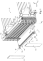
- the heating module 10 which is intended to equip a station (not shown) for heating preforms.
- the heating module 10 comprises a rack 12 for supporting several identical heating devices 14.
- each heating device 14 comprises a lamp 16.
- the lamp 16 comprises a tubular bulb 18 with a longitudinal axis "A".
- the bulb 18 comprises a hollow central tubular section 18A which is hermetically closed at its two longitudinal ends by two pinches 18B.
- the two pinches 18B are flattened in a transverse longitudinal plane.
- the hollow tubular section 18A contains means (not shown) for emitting electromagnetic radiation capable of heating the thermoplastic material constituting the preform, for example infrared radiation.
- This is for example a longitudinal filament which extends between the two pinches 18B and which is immersed in an atmosphere suitable for emitting the heating radiation.
- the atmosphere contains a halogen gas.
- the bulb 18 is made of a transparent, heat-resistant material, for example quartz glass.
- the lamp 16 also comprises two bases 20, each of which is fixed to an associated clamp 18B.
- Each base 20 has a parallelepiped envelope which comprises an upper horizontal face 22, a lower horizontal face 24, a front longitudinal vertical face 26, and a rear longitudinal vertical face 28.
- Each base 20 also comprises a transverse vertical face 30, called the inner face 30, which faces the bulb 18 and which comprises a passage orifice for the free end of the associated clamp 18B.
- Each base 20 contains means (not shown) for controlling the supply of electricity to the filament.
- Each base 20 is fixed in a non-removable manner to the associated clamp 18B of the bulb 18, for example by means of cement.
- the lamp 16 comprises two free end sections 32, each of which comprises a pinch 18B at the end of the bulb and the base 20 fixed to said pinch 18B.
- Each heating device 14 also comprises a longitudinal reflector 34 which is arranged transversely opposite a rear face of the tubular section 18A of the bulb 18. As shown in Figure 3 , when assembled with the lamp 16, the reflector 34 is arranged at a determined transverse distance "D" from the tubular section 18A.
- the reflector 34 is here formed of a plurality of similar blocks 36 which are carried by a support element formed by a longitudinal support slide 38.
- Each block 36 has a concave cylindrical front face 40 for reflecting the electromagnetic radiation which houses the tubular section 18A of the bulb 18.
- Each block 36 further comprises a rear portion forming a slide 42 which is received in sliding longitudinal in slide 38.
- the slide 38 is here produced by profiling a metal sheet which has in cross section a "C" shape open transversely towards the front.
- the blocks 36 are threaded in a row longitudinally in the slide 38 so that their front faces 40 form a single reflection face of the same length as the tubular section 18A of the bulb 18. As shown in Figure 7 , the blocks 36 are immobilized longitudinally by two transverse retaining lugs 44, each of which extends transversely forward across the slide 38.
- the slide 38 is for example made of stainless steel while the blocks 36 are made of ceramic.
- Each retaining lug 44 is here formed integrally with the slide 38, for example by cutting and bending.
- the heating device 14 is intended to be formed by assembling the lamp 16 with the reflector 34 to form a solid assembly.
- two members 46 for holding the lamp 16 in transverse position relative to the reflector 34 are each fixed to an associated longitudinal end of the reflector 34. These holding members 46 make it possible to correctly position the reflection face 40 of the reflector 34 at the determined distance "D" from the tubular section 18A of the bulb 18.
- these holding members 46 make it possible to hold the lamp 16 longitudinally in position relative to the reflector 34 so that the reflection face 40 is opposite the entire tubular section 18A of the bulb 18.
- the holding organs 46 will be described in more detail later.
- the heating devices 14 thus assembled are arranged in the support rack 12 one above the other, as shown in Figure 1 .
- the rack 12 comprises two columns 12A, 12B arranged longitudinally on either side of the space intended to receive the tubular sections 18A of the lamps 16.
- each column 12A, 12B has a rake shape provided with transverse teeth 48 extending forward from the associated column 12A, 12B.
- Two adjacent teeth 48 vertically delimit a transverse groove 50 open towards the front which is intended to receive an associated base 20 of a lamp 16 in transverse sliding.
- Each base 20 is received with a vertical clearance "j" in the associated groove 50.
- Each rake 12A, 12B has a longitudinal width less than the longitudinal length of a base 20.
- Each heating device 16 is thus carried by a lower tooth 48 of the groove 50.
- the heating devices 16 are then trapped transversely in their grooves 50 by two transverse vertical covers 52 which are each fixed against a column 12A, 12B to close the grooves 50 transversely towards the front.
- Each groove 50 further has a transverse depth greater than the transverse width of a base 20 to allow the transverse position of each heating device 16 to be adjusted relative to the preforms.
- the heating devices 16 are immobilized transversely by shims 53 which are interposed between the base 20 and the bottom of the groove 50 and/or the cover 52.
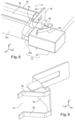
- each free end section 32 of the lamp 16 previously equipped with its base 20 is mounted on each holding member 46 by reversible fitting of a part of the free end section 32 of the lamp 16 with a housing 54 of complementary shape in a direction orthogonal to the longitudinal direction "L".
- the lamp 16 is mounted on each holding member 46 by reversible interlocking of the clamps 18B with a slot 54 supporting each holding member 46 in a transverse direction, from front to back.
- the two holding members 46 being identical, only one of them will be described subsequently, the description being applicable by symmetry to the other holding member.
- the holding member 46 has a parallel upper finger 56 and a lower finger 56 which extend transversely forward from a rear base 58.
- the two fingers 56 extend in the same vertical plane.
- the fingers 56 vertically delimit the slot 54.
- the slot 54 is thus open transversely forward, while it is delimited transversely rearward by a bottom 60 formed by a vertical edge of the base 58.
- the base 58 and the fingers 56 are formed from one piece, for example by cutting and bending a transverse vertical metal sheet.
- the rear base 58 forms a plate which extends in a vertical transverse plane.
- the holding member 46 is intended to be fixed to the reflector 34 by welding the base 58 against a vertical support tab 62 which extends transversely towards the rear from a longitudinal end edge of the slide 38.
- the fingers project transversely towards the front relative to the reflection face 40 of the blocks 36 so as to allow the clamps 18B to fit together.
- each holding member 46 is formed by an independent part which is fixed to the reflector, in particular by welding.
- each holding member is made integrally with a component of the reflector.
- the slide 38, the retaining lugs 44 and the support tabs 62 are made from one piece.
- the support tabs 62 are made by folding the longitudinal ends of the sheet metal forming a rear wall of the slide 38.
- the retaining lugs 44 are made by cutting and folding a central portion of the support tabs 62 in the other direction.
- the fingers 56 of the holding member 46 are advantageously elastically deformable in horizontal flexion and the slot 54 is dimensioned to receive the pinch 18B of the bulb 18 with a vertical holding clearance that is wide enough to allow the pinch 18B to slide in the slot 54, but small enough for the pinch 18B to be held in position by wedging against the edges of the slot 54 when the lamp 16 is left free in the slot 54.
- the holding clearance allows an imperceptible pivoting of the lamp 16 around its longitudinal axis so that the pinch 18B is in simultaneous contact with the two opposite edges of the slot 54, thus causing a transverse blocking of the lamp 16 in the slot 54.
- the disassembly of the lamp 16 by disengagement requires the operator in charge to orient the pinches 18B in a transverse plane by slightly pivoting the lamp 16 around its longitudinal axis so that the pinch 18B is no longer trapped by the edges of the slot 54.
- the fingers 56 are curved so as to have an elbow 64 which projects outwards towards the inner face 30 of the associated base 20.
- the elbows 64 of the two opposite holding members 46 are intended to come into contact with their associated base 20 to longitudinally center the lamp 16 relative to the reflector 34 by elastic bending of the fingers 56.
- a stop 66 is also arranged on the holding member 46 to stop the sliding of the lamp 16 in the slot 54 at the determined transverse distance "D" from the reflector 34.
- the stop 66 is here formed by the front face of a vertical wing which extends longitudinally projecting outwards from the base 58 of the holding member 46. This stop 66 is intended to come into contact with the rear face 28 of the associated base 20 when the pinch 18B of the lamp 16 is inserted into the slot 54 of the holding member 46.
- the stop 66 is formed by an independent element which is fixed, for example by welding, against the base 58 of the holding member 46.
- a vertical fixing wing 68 extends transversely towards the rear from an internal edge of the stop 66.
- the wing 68 and the stop 66 are advantageously made in one piece by folding a metal sheet, thus forming a bracket.
- the bottom 60 of the slot 54 of the holding member 46 is arranged transversely at a distance from the pinching 18B of the stop 66 when the base 20 is pressing against the stop 66 so that the pinching 18B of the lamp 16 does not come into abutment against the bottom 60. This makes it possible to prevent the pinching 18B from being stuck at the bottom 60 of the slot 54, in particular when the pinching 18B is particularly thick due to the manufacturing tolerances of the bulb 18.
- the bottom of the slot forms the transverse positioning stop of the lamp relative to the reflector.
- the heating device 14 when the heating device 14 is arranged in the rack 12, it is supported only by vertical support of the bases 20 on the lower teeth 48. However, the reflector 34 fixed in a removable manner on the lamp 16 moves the center of gravity of the heating device 14 transversely towards the rear relative to the bases 20. The bases 20 being received with a vertical clearance "j" in the grooves 50, the heating device 14 has a tendency to tilt towards the rear around a longitudinal axis. To avoid this tilting, the heating device 14 comprises at least one stabilizing member 70 to prevent the heating device 14 from tilting relative to the rack 12 of the heating module 10.
- the stabilizing member 70 is here formed by a horizontal tab which extends transversely forward from an upper edge of the stop 66.
- the stabilizing member 70 thus extends above the upper face 22 of the associated base 20 at a vertical distance sufficient to substantially reduce the vertical play of the base 20 in the groove 50. There nevertheless remains sufficient vertical operating play to allow the heating device 14 to slide in the associated groove 50.
- the stabilizing member 70 thus forms a contact tab with the tooth 48 which delimits the groove 50 at the top to prevent the heating device 14 from tilting backwards.
- the stabilizing member 70 is here made integrally with the stop 66, for example by folding a metal sheet.
- the blocks 36 are first threaded longitudinally into the slide 38 by means of their slide 42. Then the retaining lugs 44 are folded across the longitudinal end openings to trap blocks 36.
- the holding member 46 is fixed, for example by welding, against the support legs 62 previously folded backwards by bending.
- the independent element carrying the stop 66 and the stabilizing member 70 is fixed, for example by welding, against the base 58 of the holding member 46, before, during or after the fixing of the holding member 46 on the reflector 34.
- the reflector 34, the holding member 46, the stop 66 and the stabilizing member 70 thus form a fixed, non-removable assembly.
- the lamp 16 is then placed in position on the reflector 34. It will be understood that the lamp 16 is considered as a whole mounted prior to its assembly with the reflector 34.
- the various components of the lamp 16, in particular the bases 20, have been mounted, and here definitively fixed on the bulb 18, before the lamp 16 is placed in position on the reflector 34.
- the lamp 16 is arranged transversely in front of the reflector 34 so that the pinches 18B are in coincidence with the front opening of the slots 54 of the holding members 46. Then, the lamp 16 is moved transversely towards the rear so that the pinches 18B are fitted into the corresponding slots 54. The movement continues until the rear face 28 of the bases 20 is in contact against their associated stop 66.
- the lamp 16 is thus positioned to form, with the reflector 34, a solid but removable assembly forming the heating device 14.
- the lamp 16 is immobilized relative to the reflector 34.
- the lamp 16 is held in position relative to the reflector 34 by being wedged between the fingers 56. This prevents the heating device 14 from becoming dislodged before or during its insertion into the rack 12.
- the heating device 14 thus forming a solid assembly, is then inserted transversely into the corresponding grooves 50 of the rack 12, possibly with the appropriate shims 53.
- the stabilizing member 70 is then in contact with the upper tooth 48 to prevent the heating device 14 from tilting backwards.
- This operation is advantageously carried out by leaving the reflector 34 in place in the rack 12.
- the entire heating device 14 is removed from the rack 12 before proceeding with the dismantling of the lamp 16.
- a new lamp 16 identical to the previous one can then be placed in position on the reflector 34 according to the method previously described.
- the part to be fitted into the end section 32 of the lamp is no longer formed by the pinching 18B but by the base 20.
- the fingers 56 and the slot 54 are arranged longitudinally on the external side of the wing carrying the stop 66. This advantageously makes it possible to produce the holding member 46, the stop 66, the stabilizing member 70 and the base 58 in a single piece, for example by cutting and folding a metal sheet.
- the wing carrying the stop 66 then extends longitudinally from the base 58 of the holding member 46 to form a square.
- the fingers 56 occupy a greater vertical space than in the first embodiment.
- the heating device 14 produced according to the teachings of the invention advantageously makes it possible to reuse the reflector 34 with several lamps 16. This is all the more advantageous since the reflector wears considerably less quickly than a lamp 16.
Landscapes
- Engineering & Computer Science (AREA)
- Manufacturing & Machinery (AREA)
- Mechanical Engineering (AREA)
- Physics & Mathematics (AREA)
- Thermal Sciences (AREA)
- Fastening Of Light Sources Or Lamp Holders (AREA)
- Fixing For Electrophotography (AREA)
- Non-Portable Lighting Devices Or Systems Thereof (AREA)
- Resistance Heating (AREA)
Claims (12)
- Vorrichtung (14) zum Heizen, insbesondere zum Heizen von Vorformen aus thermoplastischem Material, das eine einstückige Baugruppe bildet, die dazu bestimmt ist, in einem Gestell (12) zum Tragen mehrerer identischer Vorrichtungen (14) zum Heizen eines Moduls (10) zum Heizen angeordnet zu werden, wobei die Vorrichtung (14) zum Heizen umfasst:- eine einzelne Lampe (16), die eine röhrenförmige Glühbirne (18) mit Längsachse (A) umfasst, wobei die Lampe (16) einen mittleren röhrenförmigen, hohlen Abschnitt (18A) der Glühbirne (18) und zwei freie Endabschnitte (32) umfasst, von denen jeder eine Endklemme (18B) der Glühbirne (18) und einen Endsockel (20) umfasst, der an der Klemme befestigt ist, wobei der röhrenförmige Abschnitt (18A) an seinen zwei Längsenden durch die zwei Klemmen (18B) hermetisch verschlossen ist, wobei die zwei Klemmen (18B) in einer quergerichteten Längsebene abgeflacht sind;- mindestens einen Reflektor (34), der sich in Längsrichtung erstreckt;- zwei Bauteile (46) zum Halten der Lampe (16) in Bezug auf den Reflektor (34), wobei jedes Bauteil (46) zum Halten an dem Reflektor (34) befestigt ist, wobei jeder Abschnitt (32) mit freiem Ende der Lampe (16), der zuvor mit seinem Sockel (20) ausgestattet wurde, auf abnehmbare Weise durch reversible Verschachtelung eines Teils des Abschnitts (32) mit freiem Ende der Lampe mit einem Gehäuse (54) mit komplementärer Form an jedem Bauteil (46) zum Halten montiert wird,dadurch gekennzeichnet, dass sich der mindestens eine Reflektor (34) in einem bestimmten quergerichteten Abstand (D) von der röhrenförmigen Glühbirne (18) erstreckt, und dadurch, dass die zwei Bauteile (46) zum Halten Bauteile zum Halten in quergerichteter Position sind, und dadurch, dass die reversible Verschachtelung eine Verschachtelung gemäß einer zu der Längsrichtung senkrechten Richtung ist.
- Vorrichtung (14) nach dem vorstehenden Anspruch, dadurch gekennzeichnet, dass jedes Bauteil (46) zum Halten einen quer nach vorne offenen Schlitz (54) umfasst, der dazu bestimmt ist, durch Querverschachteln den komplementären Teil des freien Endabschnitts (32) der Lampe (16) aufzunehmen, um die Lampe (16) in Bezug auf den Reflektor (34) in Position zu halten.
- Vorrichtung (14) nach dem vorstehenden Anspruch, dadurch gekennzeichnet, dass sie einen Anschlag (66) zum Stoppen der Lampe (16) in einem bestimmten Querabstand (D) zum Reflektor (34) umfasst.
- Vorrichtung nach einem der Ansprüche 2 oder 3, dadurch gekennzeichnet, dass der Schlitz (54) durch zwei elastisch verformbare Finger (56) begrenzt wird, zwischen denen der komplementäre Teil des Endabschnitts (32) der Lampe (16) mit einem vertikalen Spiel zum Halten der Lampe in verschachtelter Position aufgenommen ist.
- Vorrichtung (14) nach einem der vorstehenden Ansprüche, dadurch gekennzeichnet, dass jedes Bauteil (46) zum Halten durch ein unabhängiges Teil gebildet ist, das an dem Reflektor (34) insbesondere durch Schweißen befestigt ist.
- Vorrichtung (14) nach einem der Ansprüche 1 bis 4, dadurch gekennzeichnet, dass jedes Bauteil (46) zum Halten, kommend aus Material, mit einem Stützelement (38) des Reflektors (34) hergestellt ist.
- Vorrichtung (14) nach einem der vorstehenden Ansprüche, dadurch gekennzeichnet, dass der zu verschachtelnde Teil des Endabschnitts (32) der Lampe (16) durch die Klemme (18B) gebildet wird.
- Vorrichtung (14) nach einem der Ansprüche 1 bis 6, dadurch gekennzeichnet, dass der zu verschachtelnde Teil des Endabschnitts (32) der Lampe (16) durch den Sockel (20) gebildet wird.
- Vorrichtung (14) nach einem der vorstehenden Ansprüche, dadurch gekennzeichnet, dass jeder Endabschnitt (32) der Lampe (16) dazu bestimmt ist, quer gleitend mit vertikalem Spiel in einer zugehörigen Nut eines Heizmoduls aufgenommen zu werden, wobei die Vorrichtung (14) mindestens ein Stabilisierungsbauteil (70) umfasst, um die Drehung der Heizvorrichtung (14) um eine Längsachse in Bezug auf die Nut durch Kontakt mit einer Seite der Nut zu verhindern.
- Vorrichtung (14) nach dem vorstehenden Anspruch, dadurch gekennzeichnet, dass das Stabilisierungsbauteil (70) eine Lasche zum Kontakt mit einer Oberseite der Nut umfasst.
- Vorrichtung (14) nach einem der Ansprüche 9 oder 10, dadurch gekennzeichnet, dass das Stabilisierungsbauteil (70) durch ein unabhängiges Element gebildet wird, das mit dem Bauteil zum Halten zum Beispiel durch Schweißen befestigt ist.
- Vorrichtung (14) nach dem vorstehenden Anspruch, dadurch gekennzeichnet, dass das unabhängige Element, umfassend das Bauteil zum Halten (70), mit dem Anschlag (66) zum Stoppen der Lampe (16) versehen ist.
Applications Claiming Priority (2)
| Application Number | Priority Date | Filing Date | Title |
|---|---|---|---|
| FR1455595A FR3022610B1 (fr) | 2014-06-18 | 2014-06-18 | Dispositif de chauffage comportant une lampe montee de maniere amovible sur un reflecteur associe |
| PCT/FR2015/051565 WO2015193591A1 (fr) | 2014-06-18 | 2015-06-12 | Dispositif de chauffage comportant une lampe montée de manière amovible sur un réflecteur associé |
Publications (3)
| Publication Number | Publication Date |
|---|---|
| EP3157730A1 EP3157730A1 (de) | 2017-04-26 |
| EP3157730B1 EP3157730B1 (de) | 2018-08-01 |
| EP3157730B2 true EP3157730B2 (de) | 2025-05-21 |
Family
ID=51518993
Family Applications (1)
| Application Number | Title | Priority Date | Filing Date |
|---|---|---|---|
| EP15733824.5A Active EP3157730B2 (de) | 2014-06-18 | 2015-06-12 | Heizvorrichtung umfassend eine herausnehmbar auf einem reflektor montierte lampe |
Country Status (5)
| Country | Link |
|---|---|
| US (1) | US10368397B2 (de) |
| EP (1) | EP3157730B2 (de) |
| CN (2) | CN106660257B (de) |
| FR (1) | FR3022610B1 (de) |
| WO (1) | WO2015193591A1 (de) |
Families Citing this family (3)
| Publication number | Priority date | Publication date | Assignee | Title |
|---|---|---|---|---|
| CN106863758B (zh) * | 2017-03-23 | 2023-03-14 | 苏州普洽吹瓶科技有限公司 | 一种灯箱结构 |
| DE102017008445A1 (de) * | 2017-09-08 | 2019-03-14 | Khs Corpoplast Gmbh | Hauptreflektor für ein Heizmodul eines Heizkanals einer Formmaschine zur Formung von Behältem aus Vorformlingen |
| DE102024115123A1 (de) * | 2024-05-29 | 2025-12-04 | Khs Gmbh | Heizvorrichtung zum thermischen Konditionieren von Vorformlingen für Behälter und Anlage |
Citations (11)
| Publication number | Priority date | Publication date | Assignee | Title |
|---|---|---|---|---|
| DE3608394A1 (de) † | 1984-01-25 | 1987-09-17 | James R Roberts | Anordnung fuer indirekte beleuchtung |
| DE3904138A1 (de) † | 1989-02-11 | 1990-08-16 | Guenter Petz | Heizstrahler |
| US5549468A (en) † | 1994-10-19 | 1996-08-27 | Constar Plastics Inc. | Heating lamp assembly |
| DE29721183U1 (de) † | 1997-11-29 | 1998-01-29 | Krupp Corpoplast Masch | Vorrichtung zur Temperierung von Vorformlingen |
| DE29810061U1 (de) † | 1998-06-05 | 1999-07-08 | KRONES AG, 93073 Neutraubling | Vorrichtung zum Temperieren von Vorformlingen |
| US6005223A (en) † | 1998-03-13 | 1999-12-21 | Nissei Asb Machine Co., Ltd. | Preform heating device |
| JP2001068066A (ja) † | 1999-08-24 | 2001-03-16 | Ushio Inc | 白熱電球および白熱電球装置 |
| US20060279951A1 (en) † | 2005-06-10 | 2006-12-14 | Coarsegold Consulting, Inc. | Sealed lighting fixture having mechanisms for venting and equalizing interior air pressure |
| US7465063B2 (en) † | 2005-04-27 | 2008-12-16 | Stillman Allen M | Adjustable track lighting system adapted to support multiple types of light sources |
| EP2110225A1 (de) † | 2008-04-17 | 2009-10-21 | Krones AG | Lampenvorrichtung sowie Heizstrecke für die Erwärmung von Vorformlingen für die Herstellung von Behältnissen |
| DE102009033902A1 (de) † | 2009-07-16 | 2011-01-20 | Khs Corpoplast Gmbh & Co. Kg | Verfahren und Vorrichtung zur Blasformung von Behältern |
Family Cites Families (14)
| Publication number | Priority date | Publication date | Assignee | Title |
|---|---|---|---|---|
| US3723945A (en) * | 1972-04-03 | 1973-03-27 | L Detch | Locking means for fluorescent lamps |
| CH690095A5 (fr) * | 1995-12-07 | 2000-04-28 | Tetra Pak Plastics Ltd Tetra P | Dispositif de chauffage pour machines de transformation de matières plastiques. |
| US5968397A (en) * | 1997-06-06 | 1999-10-19 | Amana Company, L.P. | Apparatus for cooling a quartz halogen lamp with heat conducting convector secured to the lamp terminal or socket |
| US6361301B1 (en) * | 2000-02-21 | 2002-03-26 | Plastipak Packaging, Inc. | Heater assembly for blow molding plastic preforms |
| US6905230B2 (en) * | 2003-08-18 | 2005-06-14 | Nordson Corporation | UV lamp retainer system |
| JP2006344602A (ja) * | 2005-06-09 | 2006-12-21 | Samsung Electronics Co Ltd | ランプ、ランプホルダー、電源供給モジュール、それを有するバックライトアセンブリ及び表示装置 |
| DE202005020252U1 (de) * | 2005-12-23 | 2007-02-08 | Krones Ag | Vorrichtung zum Temperieren von Vorformlingen |
| KR101383981B1 (ko) * | 2006-09-14 | 2014-04-10 | 엘지디스플레이 주식회사 | 램프 고정 부재, 이를 갖는 백라이트 어셈블리 및 이를갖는 표시장치 |
| KR101503695B1 (ko) * | 2009-02-05 | 2015-03-19 | 삼성디스플레이 주식회사 | 램프 소켓, 이를 갖는 백라이트 어셈블리 및 표시 장치, 상기 램프 소켓의 제조 방법 |
| EP2483046B1 (de) * | 2009-09-29 | 2013-11-13 | Speziallampenfabrik Dr. Fischer GmbH | Anordnung einer gegenreflektorvorrichtung zur erwärmung eines objekts, anlage und heizverfahren |
| DE102010049136A1 (de) * | 2010-10-22 | 2012-04-26 | Krones Aktiengesellschaft | Heizvorrichtung zur Temperierung von Vorformlingen |
| ITRM20110319A1 (it) * | 2011-06-17 | 2012-12-18 | Ne E Automazione S P A | Impianto di riscaldamento preforme di contenitori |
| GB2495355B (en) * | 2012-07-02 | 2013-08-28 | Gew Ec Ltd | Ink curing apparatus |
| FR3008019B1 (fr) | 2013-07-04 | 2015-07-17 | Sidel Participations | Module de chauffage comportant une lampe et une lentille fixee par une bride sur une partie non emissive de la lampe |
-
2014
- 2014-06-18 FR FR1455595A patent/FR3022610B1/fr active Active
-
2015
- 2015-06-12 WO PCT/FR2015/051565 patent/WO2015193591A1/fr not_active Ceased
- 2015-06-12 US US15/318,643 patent/US10368397B2/en active Active
- 2015-06-12 CN CN201580032328.4A patent/CN106660257B/zh active Active
- 2015-06-12 EP EP15733824.5A patent/EP3157730B2/de active Active
- 2015-06-12 CN CN201911151926.XA patent/CN110936587B/zh active Active
Patent Citations (11)
| Publication number | Priority date | Publication date | Assignee | Title |
|---|---|---|---|---|
| DE3608394A1 (de) † | 1984-01-25 | 1987-09-17 | James R Roberts | Anordnung fuer indirekte beleuchtung |
| DE3904138A1 (de) † | 1989-02-11 | 1990-08-16 | Guenter Petz | Heizstrahler |
| US5549468A (en) † | 1994-10-19 | 1996-08-27 | Constar Plastics Inc. | Heating lamp assembly |
| DE29721183U1 (de) † | 1997-11-29 | 1998-01-29 | Krupp Corpoplast Masch | Vorrichtung zur Temperierung von Vorformlingen |
| US6005223A (en) † | 1998-03-13 | 1999-12-21 | Nissei Asb Machine Co., Ltd. | Preform heating device |
| DE29810061U1 (de) † | 1998-06-05 | 1999-07-08 | KRONES AG, 93073 Neutraubling | Vorrichtung zum Temperieren von Vorformlingen |
| JP2001068066A (ja) † | 1999-08-24 | 2001-03-16 | Ushio Inc | 白熱電球および白熱電球装置 |
| US7465063B2 (en) † | 2005-04-27 | 2008-12-16 | Stillman Allen M | Adjustable track lighting system adapted to support multiple types of light sources |
| US20060279951A1 (en) † | 2005-06-10 | 2006-12-14 | Coarsegold Consulting, Inc. | Sealed lighting fixture having mechanisms for venting and equalizing interior air pressure |
| EP2110225A1 (de) † | 2008-04-17 | 2009-10-21 | Krones AG | Lampenvorrichtung sowie Heizstrecke für die Erwärmung von Vorformlingen für die Herstellung von Behältnissen |
| DE102009033902A1 (de) † | 2009-07-16 | 2011-01-20 | Khs Corpoplast Gmbh & Co. Kg | Verfahren und Vorrichtung zur Blasformung von Behältern |
Non-Patent Citations (1)
| Title |
|---|
| Dictionnaire "LE NOUVEAU PETIT ROBERT, adjectif"déterminé, ée". page 727, 2002 † |
Also Published As
| Publication number | Publication date |
|---|---|
| CN110936587A (zh) | 2020-03-31 |
| US20170135153A1 (en) | 2017-05-11 |
| WO2015193591A1 (fr) | 2015-12-23 |
| FR3022610B1 (fr) | 2016-07-15 |
| CN110936587B (zh) | 2022-03-18 |
| CN106660257A (zh) | 2017-05-10 |
| EP3157730B1 (de) | 2018-08-01 |
| EP3157730A1 (de) | 2017-04-26 |
| US10368397B2 (en) | 2019-07-30 |
| FR3022610A1 (fr) | 2015-12-25 |
| CN106660257B (zh) | 2020-01-21 |
Similar Documents
| Publication | Publication Date | Title |
|---|---|---|
| EP3157730B2 (de) | Heizvorrichtung umfassend eine herausnehmbar auf einem reflektor montierte lampe | |
| EP0127496A1 (de) | Vorrichtung zur Erzeugung infraroter oder ultravioletter Strahlung | |
| EP0288376B1 (de) | Befestigungseinrichtung für Platten einer Fassadenverkleidung | |
| EP3016791B1 (de) | Heizmodul mit einer lampe und einer linse, befestigt an einer schiene an einem emissionsfreien teil der lampe | |
| FR2749286A1 (fr) | Dispositif de convoyage d'objets munis d'un goulot ou similaire tels que par exemple des bouteilles, flacons ou autres et dispositif de chargement de tels objets concus pour ledit dispositif de convoyage | |
| EP2592335B1 (de) | Gehäuse zur Wärmeableitung | |
| EP0382108A1 (de) | Laser mit Halterungsvorrichtung des aktiven Materials und Halterungsvorrichtung für den Laseraufbau | |
| EP0204791B1 (de) | Feuerraumwand mit luftzuführungsdüsen, die aus zwei sich ergänzenden teilen geformt sind | |
| EP1867918B1 (de) | Scheinwerfer, der ein feststehendes, aufgesetztes Halterungselement umfasst, auf dem ein Scheinwerfer schwenkbar montiert ist | |
| EP0014123A2 (de) | Verfahren und Vorrichtung zum miteinander Verbinden von Kanalteilstücken mit Fluidumzug | |
| EP4076901B1 (de) | Vorrichtung zum erwärmen von kunststoffrohlingen, die eine vorrichtung zum schutz von vorformlingshälsen umfasst | |
| EP0801515B1 (de) | Widerstandvorrichtung zum Erwärmen von Behältern, bzw. Laborbehältern | |
| EP0975919A1 (de) | Heizkörper für einen gas- oder ölbeheizten kessel und module zur herstellung davon | |
| EP0565427B1 (de) | Vorrichtung zum Transportieren von Leiterplatten für eine Anlage zur thermischen Behandlung durch Konvektion und Installation zu seiner Verwendung | |
| FR2748258A1 (fr) | Insert en kit pour le vieillissement d'une boisson alcoolisee a l'interieur d'un receptacle | |
| FR2980099A1 (fr) | Cartouche de lampe a decharge pour une poignee d'un appareil de phototraitement | |
| EP1387123B1 (de) | Strahlungsbrenner | |
| EP2955002B1 (de) | Gehäuse zur herstellung eines kraftfahrzeug-scheinwerfers | |
| EP1369073B1 (de) | Verbesserter Brotschlitten für Brotröster | |
| FR2684617A1 (fr) | Retroviseur pour un vehicule. | |
| EP2369259A2 (de) | Zusammenklappbare Vorrichtung zur Konzentration eines elektromagnetischen Strahlenbündels, und Solarkochgerät, das mit einer solchen Vorrichtung ausgestattet ist | |
| EP0814302A1 (de) | Selbstregulierte Heizvorrichtung für Heizöl | |
| FR2996908A1 (fr) | Installation solaire a concentration lineaire et reflecteur secondaire pouvant etre utilise dans une telle installation | |
| FR2939418A1 (fr) | Dispositif de realisation et de conditionnement d'au moins un article alimentaire | |
| FR2471543A2 (fr) | Procede et dispositif pour le raccord de troncons de gaine de circulation de fluide |
Legal Events
| Date | Code | Title | Description |
|---|---|---|---|
| STAA | Information on the status of an ep patent application or granted ep patent |
Free format text: STATUS: THE INTERNATIONAL PUBLICATION HAS BEEN MADE |
|
| PUAI | Public reference made under article 153(3) epc to a published international application that has entered the european phase |
Free format text: ORIGINAL CODE: 0009012 |
|
| STAA | Information on the status of an ep patent application or granted ep patent |
Free format text: STATUS: REQUEST FOR EXAMINATION WAS MADE |
|
| 17P | Request for examination filed |
Effective date: 20161216 |
|
| AK | Designated contracting states |
Kind code of ref document: A1 Designated state(s): AL AT BE BG CH CY CZ DE DK EE ES FI FR GB GR HR HU IE IS IT LI LT LU LV MC MK MT NL NO PL PT RO RS SE SI SK SM TR |
|
| AX | Request for extension of the european patent |
Extension state: BA ME |
|
| DAV | Request for validation of the european patent (deleted) | ||
| DAX | Request for extension of the european patent (deleted) | ||
| GRAP | Despatch of communication of intention to grant a patent |
Free format text: ORIGINAL CODE: EPIDOSNIGR1 |
|
| STAA | Information on the status of an ep patent application or granted ep patent |
Free format text: STATUS: GRANT OF PATENT IS INTENDED |
|
| INTG | Intention to grant announced |
Effective date: 20180419 |
|
| GRAS | Grant fee paid |
Free format text: ORIGINAL CODE: EPIDOSNIGR3 |
|
| GRAA | (expected) grant |
Free format text: ORIGINAL CODE: 0009210 |
|
| STAA | Information on the status of an ep patent application or granted ep patent |
Free format text: STATUS: THE PATENT HAS BEEN GRANTED |
|
| AK | Designated contracting states |
Kind code of ref document: B1 Designated state(s): AL AT BE BG CH CY CZ DE DK EE ES FI FR GB GR HR HU IE IS IT LI LT LU LV MC MK MT NL NO PL PT RO RS SE SI SK SM TR |
|
| REG | Reference to a national code |
Ref country code: GB Ref legal event code: FG4D Free format text: NOT ENGLISH |
|
| REG | Reference to a national code |
Ref country code: CH Ref legal event code: EP Ref country code: AT Ref legal event code: REF Ref document number: 1023790 Country of ref document: AT Kind code of ref document: T Effective date: 20180815 |
|
| REG | Reference to a national code |
Ref country code: IE Ref legal event code: FG4D Free format text: LANGUAGE OF EP DOCUMENT: FRENCH |
|
| REG | Reference to a national code |
Ref country code: DE Ref legal event code: R096 Ref document number: 602015014344 Country of ref document: DE |
|
| REG | Reference to a national code |
Ref country code: NL Ref legal event code: MP Effective date: 20180801 |
|
| REG | Reference to a national code |
Ref country code: LT Ref legal event code: MG4D |
|
| REG | Reference to a national code |
Ref country code: AT Ref legal event code: MK05 Ref document number: 1023790 Country of ref document: AT Kind code of ref document: T Effective date: 20180801 |
|
| PG25 | Lapsed in a contracting state [announced via postgrant information from national office to epo] |
Ref country code: NO Free format text: LAPSE BECAUSE OF FAILURE TO SUBMIT A TRANSLATION OF THE DESCRIPTION OR TO PAY THE FEE WITHIN THE PRESCRIBED TIME-LIMIT Effective date: 20181101 Ref country code: GR Free format text: LAPSE BECAUSE OF FAILURE TO SUBMIT A TRANSLATION OF THE DESCRIPTION OR TO PAY THE FEE WITHIN THE PRESCRIBED TIME-LIMIT Effective date: 20181102 Ref country code: AT Free format text: LAPSE BECAUSE OF FAILURE TO SUBMIT A TRANSLATION OF THE DESCRIPTION OR TO PAY THE FEE WITHIN THE PRESCRIBED TIME-LIMIT Effective date: 20180801 Ref country code: IS Free format text: LAPSE BECAUSE OF FAILURE TO SUBMIT A TRANSLATION OF THE DESCRIPTION OR TO PAY THE FEE WITHIN THE PRESCRIBED TIME-LIMIT Effective date: 20181201 Ref country code: LT Free format text: LAPSE BECAUSE OF FAILURE TO SUBMIT A TRANSLATION OF THE DESCRIPTION OR TO PAY THE FEE WITHIN THE PRESCRIBED TIME-LIMIT Effective date: 20180801 Ref country code: PL Free format text: LAPSE BECAUSE OF FAILURE TO SUBMIT A TRANSLATION OF THE DESCRIPTION OR TO PAY THE FEE WITHIN THE PRESCRIBED TIME-LIMIT Effective date: 20180801 Ref country code: RS Free format text: LAPSE BECAUSE OF FAILURE TO SUBMIT A TRANSLATION OF THE DESCRIPTION OR TO PAY THE FEE WITHIN THE PRESCRIBED TIME-LIMIT Effective date: 20180801 Ref country code: NL Free format text: LAPSE BECAUSE OF FAILURE TO SUBMIT A TRANSLATION OF THE DESCRIPTION OR TO PAY THE FEE WITHIN THE PRESCRIBED TIME-LIMIT Effective date: 20180801 Ref country code: BG Free format text: LAPSE BECAUSE OF FAILURE TO SUBMIT A TRANSLATION OF THE DESCRIPTION OR TO PAY THE FEE WITHIN THE PRESCRIBED TIME-LIMIT Effective date: 20181101 Ref country code: FI Free format text: LAPSE BECAUSE OF FAILURE TO SUBMIT A TRANSLATION OF THE DESCRIPTION OR TO PAY THE FEE WITHIN THE PRESCRIBED TIME-LIMIT Effective date: 20180801 Ref country code: SE Free format text: LAPSE BECAUSE OF FAILURE TO SUBMIT A TRANSLATION OF THE DESCRIPTION OR TO PAY THE FEE WITHIN THE PRESCRIBED TIME-LIMIT Effective date: 20180801 |
|
| PG25 | Lapsed in a contracting state [announced via postgrant information from national office to epo] |
Ref country code: AL Free format text: LAPSE BECAUSE OF FAILURE TO SUBMIT A TRANSLATION OF THE DESCRIPTION OR TO PAY THE FEE WITHIN THE PRESCRIBED TIME-LIMIT Effective date: 20180801 Ref country code: HR Free format text: LAPSE BECAUSE OF FAILURE TO SUBMIT A TRANSLATION OF THE DESCRIPTION OR TO PAY THE FEE WITHIN THE PRESCRIBED TIME-LIMIT Effective date: 20180801 Ref country code: LV Free format text: LAPSE BECAUSE OF FAILURE TO SUBMIT A TRANSLATION OF THE DESCRIPTION OR TO PAY THE FEE WITHIN THE PRESCRIBED TIME-LIMIT Effective date: 20180801 |
|
| PG25 | Lapsed in a contracting state [announced via postgrant information from national office to epo] |
Ref country code: ES Free format text: LAPSE BECAUSE OF FAILURE TO SUBMIT A TRANSLATION OF THE DESCRIPTION OR TO PAY THE FEE WITHIN THE PRESCRIBED TIME-LIMIT Effective date: 20180801 Ref country code: CZ Free format text: LAPSE BECAUSE OF FAILURE TO SUBMIT A TRANSLATION OF THE DESCRIPTION OR TO PAY THE FEE WITHIN THE PRESCRIBED TIME-LIMIT Effective date: 20180801 Ref country code: RO Free format text: LAPSE BECAUSE OF FAILURE TO SUBMIT A TRANSLATION OF THE DESCRIPTION OR TO PAY THE FEE WITHIN THE PRESCRIBED TIME-LIMIT Effective date: 20180801 Ref country code: EE Free format text: LAPSE BECAUSE OF FAILURE TO SUBMIT A TRANSLATION OF THE DESCRIPTION OR TO PAY THE FEE WITHIN THE PRESCRIBED TIME-LIMIT Effective date: 20180801 |
|
| REG | Reference to a national code |
Ref country code: DE Ref legal event code: R026 Ref document number: 602015014344 Country of ref document: DE |
|
| PLBI | Opposition filed |
Free format text: ORIGINAL CODE: 0009260 |
|
| PLAX | Notice of opposition and request to file observation + time limit sent |
Free format text: ORIGINAL CODE: EPIDOSNOBS2 |
|
| PG25 | Lapsed in a contracting state [announced via postgrant information from national office to epo] |
Ref country code: SM Free format text: LAPSE BECAUSE OF FAILURE TO SUBMIT A TRANSLATION OF THE DESCRIPTION OR TO PAY THE FEE WITHIN THE PRESCRIBED TIME-LIMIT Effective date: 20180801 Ref country code: DK Free format text: LAPSE BECAUSE OF FAILURE TO SUBMIT A TRANSLATION OF THE DESCRIPTION OR TO PAY THE FEE WITHIN THE PRESCRIBED TIME-LIMIT Effective date: 20180801 Ref country code: SK Free format text: LAPSE BECAUSE OF FAILURE TO SUBMIT A TRANSLATION OF THE DESCRIPTION OR TO PAY THE FEE WITHIN THE PRESCRIBED TIME-LIMIT Effective date: 20180801 |
|
| 26 | Opposition filed |
Opponent name: KRONES AG Effective date: 20190430 |
|
| PG25 | Lapsed in a contracting state [announced via postgrant information from national office to epo] |
Ref country code: SI Free format text: LAPSE BECAUSE OF FAILURE TO SUBMIT A TRANSLATION OF THE DESCRIPTION OR TO PAY THE FEE WITHIN THE PRESCRIBED TIME-LIMIT Effective date: 20180801 |
|
| PLBB | Reply of patent proprietor to notice(s) of opposition received |
Free format text: ORIGINAL CODE: EPIDOSNOBS3 |
|
| PG25 | Lapsed in a contracting state [announced via postgrant information from national office to epo] |
Ref country code: MC Free format text: LAPSE BECAUSE OF FAILURE TO SUBMIT A TRANSLATION OF THE DESCRIPTION OR TO PAY THE FEE WITHIN THE PRESCRIBED TIME-LIMIT Effective date: 20180801 |
|
| REG | Reference to a national code |
Ref country code: CH Ref legal event code: PL |
|
| GBPC | Gb: european patent ceased through non-payment of renewal fee |
Effective date: 20190612 |
|
| REG | Reference to a national code |
Ref country code: BE Ref legal event code: MM Effective date: 20190630 |
|
| PG25 | Lapsed in a contracting state [announced via postgrant information from national office to epo] |
Ref country code: TR Free format text: LAPSE BECAUSE OF FAILURE TO SUBMIT A TRANSLATION OF THE DESCRIPTION OR TO PAY THE FEE WITHIN THE PRESCRIBED TIME-LIMIT Effective date: 20180801 |
|
| PG25 | Lapsed in a contracting state [announced via postgrant information from national office to epo] |
Ref country code: IE Free format text: LAPSE BECAUSE OF NON-PAYMENT OF DUE FEES Effective date: 20190612 Ref country code: GB Free format text: LAPSE BECAUSE OF NON-PAYMENT OF DUE FEES Effective date: 20190612 |
|
| PG25 | Lapsed in a contracting state [announced via postgrant information from national office to epo] |
Ref country code: LU Free format text: LAPSE BECAUSE OF NON-PAYMENT OF DUE FEES Effective date: 20190612 Ref country code: BE Free format text: LAPSE BECAUSE OF NON-PAYMENT OF DUE FEES Effective date: 20190630 Ref country code: CH Free format text: LAPSE BECAUSE OF NON-PAYMENT OF DUE FEES Effective date: 20190630 Ref country code: LI Free format text: LAPSE BECAUSE OF NON-PAYMENT OF DUE FEES Effective date: 20190630 |
|
| PG25 | Lapsed in a contracting state [announced via postgrant information from national office to epo] |
Ref country code: PT Free format text: LAPSE BECAUSE OF FAILURE TO SUBMIT A TRANSLATION OF THE DESCRIPTION OR TO PAY THE FEE WITHIN THE PRESCRIBED TIME-LIMIT Effective date: 20181201 |
|
| APBM | Appeal reference recorded |
Free format text: ORIGINAL CODE: EPIDOSNREFNO |
|
| APBP | Date of receipt of notice of appeal recorded |
Free format text: ORIGINAL CODE: EPIDOSNNOA2O |
|
| APAH | Appeal reference modified |
Free format text: ORIGINAL CODE: EPIDOSCREFNO |
|
| APBM | Appeal reference recorded |
Free format text: ORIGINAL CODE: EPIDOSNREFNO |
|
| APBP | Date of receipt of notice of appeal recorded |
Free format text: ORIGINAL CODE: EPIDOSNNOA2O |
|
| PG25 | Lapsed in a contracting state [announced via postgrant information from national office to epo] |
Ref country code: CY Free format text: LAPSE BECAUSE OF FAILURE TO SUBMIT A TRANSLATION OF THE DESCRIPTION OR TO PAY THE FEE WITHIN THE PRESCRIBED TIME-LIMIT Effective date: 20180801 |
|
| APBQ | Date of receipt of statement of grounds of appeal recorded |
Free format text: ORIGINAL CODE: EPIDOSNNOA3O |
|
| PG25 | Lapsed in a contracting state [announced via postgrant information from national office to epo] |
Ref country code: MT Free format text: LAPSE BECAUSE OF FAILURE TO SUBMIT A TRANSLATION OF THE DESCRIPTION OR TO PAY THE FEE WITHIN THE PRESCRIBED TIME-LIMIT Effective date: 20180801 Ref country code: HU Free format text: LAPSE BECAUSE OF FAILURE TO SUBMIT A TRANSLATION OF THE DESCRIPTION OR TO PAY THE FEE WITHIN THE PRESCRIBED TIME-LIMIT; INVALID AB INITIO Effective date: 20150612 |
|
| PG25 | Lapsed in a contracting state [announced via postgrant information from national office to epo] |
Ref country code: MK Free format text: LAPSE BECAUSE OF FAILURE TO SUBMIT A TRANSLATION OF THE DESCRIPTION OR TO PAY THE FEE WITHIN THE PRESCRIBED TIME-LIMIT Effective date: 20180801 |
|
| P01 | Opt-out of the competence of the unified patent court (upc) registered |
Effective date: 20230425 |
|
| APBU | Appeal procedure closed |
Free format text: ORIGINAL CODE: EPIDOSNNOA9O |
|
| PUAH | Patent maintained in amended form |
Free format text: ORIGINAL CODE: 0009272 |
|
| STAA | Information on the status of an ep patent application or granted ep patent |
Free format text: STATUS: PATENT MAINTAINED AS AMENDED |
|
| 27A | Patent maintained in amended form |
Effective date: 20250521 |
|
| AK | Designated contracting states |
Kind code of ref document: B2 Designated state(s): AL AT BE BG CH CY CZ DE DK EE ES FI FR GB GR HR HU IE IS IT LI LT LU LV MC MK MT NL NO PL PT RO RS SE SI SK SM TR |
|
| REG | Reference to a national code |
Ref country code: DE Ref legal event code: R102 Ref document number: 602015014344 Country of ref document: DE |
|
| PGFP | Annual fee paid to national office [announced via postgrant information from national office to epo] |
Ref country code: DE Payment date: 20250520 Year of fee payment: 11 |
|
| PGFP | Annual fee paid to national office [announced via postgrant information from national office to epo] |
Ref country code: IT Payment date: 20250520 Year of fee payment: 11 |
|
| PGFP | Annual fee paid to national office [announced via postgrant information from national office to epo] |
Ref country code: FR Payment date: 20250521 Year of fee payment: 11 |