EP0288376B1 - Befestigungseinrichtung für Platten einer Fassadenverkleidung - Google Patents
Befestigungseinrichtung für Platten einer Fassadenverkleidung Download PDFInfo
- Publication number
- EP0288376B1 EP0288376B1 EP19880400947 EP88400947A EP0288376B1 EP 0288376 B1 EP0288376 B1 EP 0288376B1 EP 19880400947 EP19880400947 EP 19880400947 EP 88400947 A EP88400947 A EP 88400947A EP 0288376 B1 EP0288376 B1 EP 0288376B1
- Authority
- EP
- European Patent Office
- Prior art keywords
- clip
- flange
- longitudinal member
- panels
- plates
- Prior art date
- Legal status (The legal status is an assumption and is not a legal conclusion. Google has not performed a legal analysis and makes no representation as to the accuracy of the status listed.)
- Expired - Lifetime
Links
- 238000005253 cladding Methods 0.000 title description 2
- 238000004519 manufacturing process Methods 0.000 claims description 9
- 239000011324 bead Substances 0.000 claims description 2
- 230000000717 retained effect Effects 0.000 claims description 2
- 239000000463 material Substances 0.000 description 10
- 230000008901 benefit Effects 0.000 description 3
- 230000005540 biological transmission Effects 0.000 description 3
- 230000000694 effects Effects 0.000 description 3
- 239000011248 coating agent Substances 0.000 description 2
- 238000000576 coating method Methods 0.000 description 2
- 238000012423 maintenance Methods 0.000 description 2
- XLYOFNOQVPJJNP-UHFFFAOYSA-N water Substances O XLYOFNOQVPJJNP-UHFFFAOYSA-N 0.000 description 2
- 230000001627 detrimental effect Effects 0.000 description 1
- 238000006073 displacement reaction Methods 0.000 description 1
- 238000005516 engineering process Methods 0.000 description 1
- 238000003780 insertion Methods 0.000 description 1
- 230000037431 insertion Effects 0.000 description 1
- 238000009434 installation Methods 0.000 description 1
- 239000011810 insulating material Substances 0.000 description 1
- 239000012212 insulator Substances 0.000 description 1
- 230000014759 maintenance of location Effects 0.000 description 1
- 239000002184 metal Substances 0.000 description 1
- 238000000034 method Methods 0.000 description 1
- 230000035515 penetration Effects 0.000 description 1
- 239000004033 plastic Substances 0.000 description 1
- 239000002984 plastic foam Substances 0.000 description 1
- 238000011084 recovery Methods 0.000 description 1
- 239000007787 solid Substances 0.000 description 1
Images


Classifications
-
- E—FIXED CONSTRUCTIONS
- E04—BUILDING
- E04F—FINISHING WORK ON BUILDINGS, e.g. STAIRS, FLOORS
- E04F13/00—Coverings or linings, e.g. for walls or ceilings
- E04F13/07—Coverings or linings, e.g. for walls or ceilings composed of covering or lining elements; Sub-structures therefor; Fastening means therefor
- E04F13/08—Coverings or linings, e.g. for walls or ceilings composed of covering or lining elements; Sub-structures therefor; Fastening means therefor composed of a plurality of similar covering or lining elements
- E04F13/0801—Separate fastening elements
- E04F13/0803—Separate fastening elements with load-supporting elongated furring elements between wall and covering elements
- E04F13/081—Separate fastening elements with load-supporting elongated furring elements between wall and covering elements with additional fastening elements between furring elements and covering elements
- E04F13/0821—Separate fastening elements with load-supporting elongated furring elements between wall and covering elements with additional fastening elements between furring elements and covering elements the additional fastening elements located in-between two adjacent covering elements
- E04F13/0826—Separate fastening elements with load-supporting elongated furring elements between wall and covering elements with additional fastening elements between furring elements and covering elements the additional fastening elements located in-between two adjacent covering elements engaging side grooves running along the whole length of the covering elements
Definitions
- the present invention relates to a device for fixing the plates of a facade covering according to the preamble of claim 1.
- Façade coverings and in particular cladding often use facings constituted by thin plates which are arranged with open horizontal and vertical joints without any overlap and which are supported by a primary framework, mounted on the wall to be coated.
- the plates are fixed to the primary framework for example by means of members which pass through them such as nails, screws, rivets or the like. But in this case all the fixing heads remain visible, which is detrimental to the overall appearance of the facing. In addition, the crossings of the fixing members risk being incipient fractures when the material which constitutes the plates does not have a sufficiently high resistance.
- profiles most often metallic, which are arranged horizontally opposite the horizontal connections between the rows of plates and constitute the beams of the primary framework.
- These profiles include a vertical wing for attachment to the wall which is extended by a core terminated by a vertical rim.
- the vertical ledge which extends both upwards and downwards, is inserted during mounting in grooves made in the upper and lower horizontal sections of the facing plates. The upper plates are thus supported by the beam while the lower plates are held against spillage by the lower part of the vertical flange.
- Such a fixing device is invisible from the outside.
- the facing plates must benefit from very small dimensional tolerances as well as high dimensional stability under thermal effect because the retention of the assembly is determined by the depth of the groove formed in the edge of the plates. Such a device is therefore difficult to use with facing plates made of inexpensive materials, the manufacture of which must allow large tolerances.
- a similar fixing can also be obtained by assembling the plates to the profile or smooth by means of lugs, hooks or clips made integral with these profiles, which enclose the entire edge of the plate and form a return on the external face of the latter. It is then possible to use particularly thin plates or made of a fragile material in which the groove is difficult to produce. Unfortunately the clip or hook thus becomes visible, which is unattractive while the requirements of very low manufacturing tolerances and dimensional stability are the same as with the previous fixing device.
- US-A-1 991 550 describes a variant of this attachment in accordance with the preamble of claim 1. Although the clips are not visible from the outside, the problems relating to tolerances and to dimensional stability remain present.
- the present invention therefore aims to provide a device for fixing the plates of a facade coating which while being simple to perform, can easily allow the establishment of plates of an inexpensive material, from a technology of simple manufacturing, and ensure a robust and reliable fixing, despite the installation clearances, dimensional variations and manufacturing tolerances.
- the fixing device according to the invention is characterized as described in the characterizing part of claim 1.
- the assembly wing is integral with the rail and the clip has an S-shape and comprises on the one hand a channel for receiving the assembly wing and on the other hand a flange d 'nesting on the edge of the plate.
- edge of the clip cooperates with a longitudinal groove in the edge of the plate so that it is invisible from the outside and the facing has a perfectly aesthetic appearance.
- Centering flanges of the assembly flange are also provided between the latter and the clip.
- the fixing device comprises a profile or smooth 1 which is preferably made of metal but can also be made of a rigid plastic material, and which, in the embodiments shown, is arranged horizontally so as to secure the plates of two superimposed rows, but can, of course, be used vertically to connect the plates of two rows side by side.
- the profile shown has a vertical wing 2 intended to come to bear on a support and thus allow the fixing of the profile, either directly on the wall to be coated, or on an intermediate frame with possibly an insertion of a thermal insulator, or even on a rigid insulating material such as plastic foam which covers the facade.
- This fixing is carried out by means of screws 4 passing through holes 6 of the vertical wing or by any other appropriate means, in particular to the type of support.
- the vertical wing 2 is extended at its lower part by a substantially horizontal core 8 which, in the embodiment shown in Figs 1 to 3, is terminated by a rim 10 projecting upwards and substantially parallel to the wing vertical 2.
- the wing 8 and its rim 10 constitute a support for sheets of covering materials 12 provided on their lower edge with a groove 14 and thus capable of being fitted onto the rim 10 of the profile 1, as well as the shows for example Fig. 2.
- the rim 10 is provided at its end with a bulge 16 whose width is substantially equal to that of the groove 14 so that it comes into contact with the walls of this groove and ensures centering of the plate 12 fitted.
- the height of the rim 10 is similar to that of the groove 14 so that the plate 12 is supported by the core 8 of the heddle 1.
- a second wing 18 which has a significant height relative to that of the rim 10.
- the wing 18 is further offset from this edge by a distance which corresponds to at least half the width of a covering plate 12.
- This lower vertical wing 18 is intended to cooperate with at least one clip 20 for retaining a lower plate 22 which has a longitudinal groove 24 in its upper edge 26.
- the clip or hook 20 has substantially an S shape and thus comprises on the one hand a channel 28 for fitting onto the vertical wing 18 and on the other hand a flange 30 for penetration into the groove 24 of the lower plate 22.
- the rim 30 of this clip 20 then penetrates practically to the bottom of the groove 24 of the plate 22 and the plate 32 which connects this rim to the channel 28 rests on the edge 26 of this plate.
- a heald 1 is then brought closer to the set of clips thus mounted and its vertical assembly wing 18 penetrates into each channel 28 to a depth determined by the desired distance between the rows of plates 22 and 12, this is to say according to the desired joint opening between the edges of the plates.
- Bosses, 34 which in the embodiment shown are formed on the two internal walls of the channel 28 of the clip 20 but can also be carried by the assembly wing 18 itself, ensure the centering and lateral locking of this last in the clip 20.
- the flange 30 preferably has, like the flange 10, at its end a bulge 31 which ensures its centering in the groove 24.
- the vertical wing 18 having a great height can penetrate more or less far inside the channel 28.
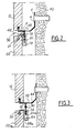
- the same beam 1 can ensure the maintenance of plates 22 of different height such as plates 22 and 22 has Figs 2 and 3.
- the rail 1 is fixed to the support 40, by means of screws 4 for example.
- the wing 18 penetrates fairly deeply into the channel 28 of the clips 20 carried by this plate 22 (Fig. 2).
- it penetrates much less deeply into the clips 20 a of a plate 22 a of the same row, the height of which is less than that of the plate 22.
- the wing 18 only enters the channel 28 a of the clip 20 a over a depth similar to the height of the rim 30.
- the plate 22 is however held securely against any spillage by the cooperation of the rim 30 and the wing 18 which still takes place over the entire height of the rim 30.
- the height of the assembly wing 18 must be at least equal to the total sum of the plate dimension differential due to manufacturing tolerances, the depth of the groove formed on the upper edge of the plate, the minimum opening of the desired joint and also the maximum dimension deviation of the plates due to shrinkage thermal.
- the device is also advantageously supplemented by the addition of breakable means acting as a stop between the clip and the heddle when the relative position of these two elements corresponds to the minimum opening of the desired joint.
- breakable means can be carried by the clip 20 and be constituted by an inclined tongue 42 carried by the plate 32 of this clip or by a tongue 44 projecting inside the channel 28 near the bottom of the latter. They can also be carried by the vertical wing 18 and have for example the shape of a tongue 48 projecting laterally from this wing or by a cylindrical boss 50 projecting on either side of the wing. This boss 50 and the tongue 48 are placed in the upper part of the wing so as to abut against the plate 32 or against the upper part of the channel 28, when the fixing device is put in place.
- These breakable means 42 to 50 thus play the role of template warning that the position of the heddle corresponds to the opening of the desired joint.
- the space between the wall 40 and the facing plates 12, 22 can constitute a ventilated air space.
- the core 8 of the heddle is provided with means for recovering and evacuating the infiltrated water comprising, for example, holes 52 and an inclined portion 54 between these holes and the vertical fixing wing 2.
- the end flange 10 of the core 8 of the heald is removed and the upper face of the core 58 of the heald 61 is provided with a hollow rib 60 open towards the outside, that is to say in the direction opposite the fixing wing 2.
- This rib is provided with a longitudinal internal projection 62 forming a hook and is extended externally by a vertical flange 64 directed upwards.
- At least one L-shaped hook 66 cooperates with the cavity of the rib 60 to hold each of the upper plates 12.
- the hook 66 has a branch 68 which penetrates into the groove 14 of the plate 12, while at opposite its head 70 is locked inside the rib 60 against the projection 62.
- the same rail can thus be used for supporting plates 12 of different dimensions.
- the hook 66 may have between its branch 68 and its head 70 a branch 72 long enough to extend over the entire edge of the plate 82 so that the branch 68 is outside the covering.
- the clip 80 for holding the lower plate also includes a plate 74 capable of extending over the entire edge of the lower plate 83 so that its rim 75 is located outside the covering.
- the upper and lower covering plates 82 and 83 are then devoid of longitudinal groove, which makes it possible to reduce their thickness.
- the core 8 of the heddle 81 (FIG. 6) with a vertical flange situated in the extension of its assembly wing.
- a vertical rim 76 preferably has a significant height and it cooperates with a substantially S-shaped clip 78 which surrounds it completely and extends over the entire edge of the facing plate 82 so as to support it.
- This clip 78 therefore has a return 79 which is visible from the outside.
- the assembly wing has two parallel walls 84 and 86 of the same height slightly spaced. Centering bosses 88 are preferably formed on the outer face of each of these wings so as to come into contact with the lateral walls of the channel 28 of each clip 20.
- the spacing of the walls 84 and 86 may be such as holes 52 of evacuation of the infiltrated rainwater are practiced between them and that they thus contribute to the recovery and evacuation of this water.
- the vertical wing may also have a substantially Y-shaped shape which is turned over and comprise a rectilinear portion 90 (FIG. 8) separating into two branches 92 and 94 which are bent so as to each comprise a vertical portion parallel to the main branch 90.
- the bosses 98 are provided on these vertical portions 96 and 94 so as to come into contact with the clip 20 and to ensure the centering of the assembly.
- the assembly wing has a main vertical wall 100 (FIG. 9) from which a tilted lateral branch 102 starts which is bent to have a vertical portion 104 parallel to the main branch, these two portions vertical being provided with bosses 108 for centering in the clip 20.
- Figs 7, 8 and 9 the vertical double-walled assembly wing is carried by a heald 1 provided with an upper edge 10, but it will clearly appear that it can be joined in the same way to a heald of another shape and in particular a heald provided with a rib 60.
- the device comprises a heddle 110 successively forming a vertical wing 112 for fixing on the support, a substantially horizontal core 114 and a flange 116 for fitting into a lower groove in the plates of covering, but this core 114 is pierced with a longitudinal slot in which comes a vertical wing 118 secured to a clip 120 for retaining the lower plate 22.
- This clip 120 then simply has the shape a stirrup, one of the branches 122 of which fits into the groove 24 of the lower plate 22 in the same manner as the flange 30 of the clip 20 and the plate 124 of which connects the two branches of the stirrup has a width slightly greater than the half thickness of the plate 22 so that the second branch 126 is very close to the internal surface of the plate 22.
- each of the two branches 122 and 126 of the stirrup 120 is terminated by a bulge 128 completing centering.
- the slot in the core 114 of the heddle 110 can be a continuous slot 117 and extend over the entire length of the profile. It is then protected by a hollow rib 130 projecting upwards which forms a channel 132 for receiving the assembly wing. Beads 134 carried for example, as shown in FIG. 10, by the internal walls of this rib, ensure the centering of the wing 118 inside the channel 132.
- the slot of the core 114 can also be simply local and have a length slightly greater than that of the wing 118 as shown at 136 in Figs. 11 and 12.
- the production of the heddle is then considerably simplified but its mounting on the clips 120 must be carried out with precision so that each of the wings 118 is exactly opposite a slot 136.
- the positioning of the covering plates is carried out in a simple manner but the latter are fixed reliably even when the plates are thin, that is to say have a thickness of less than two centimeters, and are made with large dimensional tolerances.
- Each of horizontal rows of plates can indeed be securely supported by the horizontal rail on which it rests while still being sufficiently maintained at its upper part by the clips assembled on the next rail.
- each of the plates of a vertical row can be held at its two ends by the combined action of two vertical rails and clips associated with them. Even dimensional variations due to thermal effects do not risk reducing the solidity of this assembly.
- the covering retains an aesthetic appearance, all the fixing devices being invisible and the same fixing devices making it possible to give the horizontal opening of the joints the appropriate dimension so that these joints are more or less open depending on the desired aesthetic effect.
- This invention has an additional advantage; it ensures the ease of replacing a plate of the covering, without disassembly of the surrounding plates or of the beams. Indeed, a broken plate, after being removed, can be replaced while keeping the fixing device invisible (in the case of Figures 1, 2, 3, 4, 7, 8, 9, 10) by inserting the clip (s) maintenance in the rail, then lateral sliding of these clips to position them on standby on the plates located on either side of the plate to be replaced. The new replacement plate is then fitted onto the bottom rail, kept in the vertical position, then the clips left waiting on the adjacent plates are slid towards the new plate to resume their position in which it is held.
Landscapes
- Engineering & Computer Science (AREA)
- Architecture (AREA)
- Civil Engineering (AREA)
- Structural Engineering (AREA)
- Finishing Walls (AREA)
- Connection Of Plates (AREA)
Claims (15)
Applications Claiming Priority (2)
| Application Number | Priority Date | Filing Date | Title |
|---|---|---|---|
| FR8705758A FR2614340B1 (fr) | 1987-04-23 | 1987-04-23 | Dispositif de fixation des plaques d'un revetement de facade |
| FR8705758 | 1987-04-23 |
Publications (2)
| Publication Number | Publication Date |
|---|---|
| EP0288376A1 EP0288376A1 (de) | 1988-10-26 |
| EP0288376B1 true EP0288376B1 (de) | 1991-07-03 |
Family
ID=9350407
Family Applications (1)
| Application Number | Title | Priority Date | Filing Date |
|---|---|---|---|
| EP19880400947 Expired - Lifetime EP0288376B1 (de) | 1987-04-23 | 1988-04-19 | Befestigungseinrichtung für Platten einer Fassadenverkleidung |
Country Status (4)
| Country | Link |
|---|---|
| EP (1) | EP0288376B1 (de) |
| DE (1) | DE3863470D1 (de) |
| ES (1) | ES2023263B3 (de) |
| FR (1) | FR2614340B1 (de) |
Cited By (1)
| Publication number | Priority date | Publication date | Assignee | Title |
|---|---|---|---|---|
| WO2022189390A1 (en) * | 2021-03-08 | 2022-09-15 | As Spilka Industri | Wall panel mounting tool, system and method |
Families Citing this family (18)
| Publication number | Priority date | Publication date | Assignee | Title |
|---|---|---|---|---|
| CH678742A5 (de) * | 1989-06-02 | 1991-10-31 | Ickler Sa | |
| FR2678662B1 (fr) * | 1991-07-04 | 1993-11-05 | Axter | Dispositif de fixation des plaques d'un revetement de facade. |
| SE505797C2 (sv) * | 1991-12-30 | 1997-10-13 | Nils Gunnar Jansson | Anordning för uppsättande av fasadelement av glas |
| WO1994008106A1 (en) * | 1992-09-28 | 1994-04-14 | Brian Barber | Improvements in cladding systems for buildings |
| FR2706510B1 (fr) * | 1993-06-10 | 1995-09-08 | Brezillon Entr Trav Pub Andre | Elément et ensemble de renfort pour bardage de dalles. |
| DE9420155U1 (de) * | 1994-12-16 | 1995-03-02 | Eternit AG, 10587 Berlin | FAssadenbekleidung mit horizontalen Halteprofilen |
| DE29605273U1 (de) * | 1996-03-21 | 1996-06-13 | Beig, Walter, 53783 Eitorf | Abschlußleiste für Außenisolierungen von Gebäuden |
| DE60019095D1 (de) * | 2000-07-14 | 2005-05-04 | Eurogramco S L | Vorrichtung zur Verkleidung |
| NO20004591L (no) * | 2000-09-14 | 2002-03-15 | Tore Fjeld | Anordning ved monteringsprofil |
| ES2316305B1 (es) * | 2005-06-13 | 2010-01-22 | Gresmanc Internacional, S.L. | Sistema de fijacion para fachada ventilada. |
| DE202006005470U1 (de) * | 2006-04-05 | 2006-07-27 | Hdm Gmbh | Klammer zur Befestigung von Paneelelementen |
| WO2009059392A1 (en) * | 2007-11-08 | 2009-05-14 | Lysyuk, Dmytro | Apparatus and method for installing cladding to structures |
| DE102008014079B4 (de) * | 2008-03-13 | 2016-01-07 | Ejot Baubefestigungen Gmbh | Fassadenklammer zum Anbringen von Fassadenplatten |
| ES2354920B1 (es) * | 2008-08-05 | 2012-01-23 | Wandegar 2001, S.L. | Sistema de fijación longitudinal oculta para fachadas con revestimiento rígido. |
| DE102011117281A1 (de) * | 2011-10-31 | 2013-05-02 | LängleGlas GmbH | Plattenhalter insbesondere für Glastafeln |
| ES2586736B1 (es) * | 2015-04-15 | 2017-09-07 | Cupa Innovacion S.L.U. | Fachada ventilada |
| USD903478S1 (en) | 2018-08-13 | 2020-12-01 | Eldorado Stone Operations, Llc | Positioning clip |
| US20220220730A1 (en) * | 2020-11-06 | 2022-07-14 | Henry H. Bilge | Universal z-z channel for mounting wall panels to existing wall |
Family Cites Families (7)
| Publication number | Priority date | Publication date | Assignee | Title |
|---|---|---|---|---|
| US1991550A (en) * | 1933-07-31 | 1935-02-19 | Sealed Joint Products Company | Tile construction |
| US2171221A (en) * | 1939-03-30 | 1939-08-29 | Roesch Porcelain Construction | Supporting structure for porcelain enameled pans |
| US2832102A (en) * | 1957-01-22 | 1958-04-29 | Amoruso Joseph | Veneer wall construction |
| NL6517276A (de) * | 1965-02-27 | 1966-08-29 | ||
| DE3309058A1 (de) * | 1983-03-14 | 1984-09-20 | Bernd 6701 Otterstadt Lill | Fassadenverkleidung |
| FR2550815A1 (fr) * | 1983-08-19 | 1985-02-22 | Aubin Georges | Dispositif d'accrochage mecanique de plaques pour revetements |
| DE3424375C2 (de) * | 1984-07-03 | 1997-01-16 | Bwm Duebel & Montagetech | Aufhängevorrichtung für Wandplatten mit einer an einer Wand befestigbaren Querleiste und daran eingehängten, die Wandplatten tragenden Haken |
-
1987
- 1987-04-23 FR FR8705758A patent/FR2614340B1/fr not_active Expired
-
1988
- 1988-04-19 DE DE8888400947T patent/DE3863470D1/de not_active Expired - Lifetime
- 1988-04-19 EP EP19880400947 patent/EP0288376B1/de not_active Expired - Lifetime
- 1988-04-19 ES ES88400947T patent/ES2023263B3/es not_active Expired - Lifetime
Cited By (1)
| Publication number | Priority date | Publication date | Assignee | Title |
|---|---|---|---|---|
| WO2022189390A1 (en) * | 2021-03-08 | 2022-09-15 | As Spilka Industri | Wall panel mounting tool, system and method |
Also Published As
| Publication number | Publication date |
|---|---|
| FR2614340B1 (fr) | 1989-07-28 |
| DE3863470D1 (de) | 1991-08-08 |
| ES2023263B3 (es) | 1992-01-01 |
| FR2614340A1 (fr) | 1988-10-28 |
| EP0288376A1 (de) | 1988-10-26 |
Similar Documents
| Publication | Publication Date | Title |
|---|---|---|
| EP0288376B1 (de) | Befestigungseinrichtung für Platten einer Fassadenverkleidung | |
| CA2096082A1 (fr) | Profiles pour supporter et maintenir en tension un faux plafond ou un faux mur | |
| FR2800768A1 (fr) | Dispositif pour le montage et l'immobilisation de consoles de support sur une facade de batiment ou analogue | |
| EP0433164A1 (de) | Wärmeisolierendes und feuerhemmendes Wandpaneel | |
| EP0325642B1 (de) | Punktbefestigungsvorrichtung von elementen mit einem rand, insbesondere von platten auf einer tragkonstruktion | |
| FR2754285A1 (fr) | Element de coffrage isolant pour mur en beton | |
| EP1024232B1 (de) | Deckenplatte | |
| EP0065914B1 (de) | Profile für isolierte Verkleidungen in einem Kreuzraster | |
| FR2703710A1 (fr) | Profilés pour supporter & maintenir en tension un faux plafond ou un faux mur. | |
| FR2685136A1 (fr) | Panneau, en particulier pour porte d'armoire, et notamment pour porte d'armoire electrique. | |
| FR2930315A1 (fr) | Dispositif pour le raccordement de deux elements profiles selon un angle quelconque. | |
| FR2712008A1 (fr) | Profilés pour supporter et maintenir en tension un faux plafond ou un faux mur. | |
| EP0166219A1 (de) | Verfahren zur Errichtung von Mauern aus Quadern und dabei verwendete Vorrichtung | |
| FR2941725A1 (fr) | Element d'isolation thermique pour bloc prefabrique et bloc de construction ainsi obtenu. | |
| EP2961897A1 (de) | Pfeilförmiges profil zur herstellung einer zwischendecken- oder zwischenwandplattenumschliessung | |
| WO2002101175A1 (fr) | Dispositif d'assemblage de panneaux, lattes ou lambris, a repartition de forces | |
| EP0281509B1 (de) | Fassadenziegel und ihre Aufhängvorrichtungen | |
| FR2561289A1 (fr) | Procede de fixation des plaques de bardage sur une surface support | |
| EP0791700A1 (de) | Befestigungshalterung und Abstandhalter zur Erstellung von Verkleidungen im Bausektor, und so hergestellte Verkleidungen | |
| EP0558378A1 (de) | Anordnung für Trennwand | |
| FR2558875A1 (fr) | Systeme de revetement de parois, telles que des murs ou des facades de batiments, elements d'un tel systeme et procede pour la mise en place de ce systeme | |
| WO1996035846A1 (fr) | Profiles pour supporter et maintenir en tension un faux plafond ou un faux mur | |
| FR2581410A1 (fr) | Nouveaux panneaux de veture ou bardage | |
| EP0143042B1 (de) | Klammer zum Befestigen von Verkleidungsplatten auf einer Konstruktion | |
| FR2730514A1 (fr) | Paroi de batiment, notamment paroi de couverture comportant une isolation thermique et/ou acoustique |
Legal Events
| Date | Code | Title | Description |
|---|---|---|---|
| PUAI | Public reference made under article 153(3) epc to a published international application that has entered the european phase |
Free format text: ORIGINAL CODE: 0009012 |
|
| AK | Designated contracting states |
Kind code of ref document: A1 Designated state(s): BE CH DE ES FR GB LI LU |
|
| 17P | Request for examination filed |
Effective date: 19881003 |
|
| 17Q | First examination report despatched |
Effective date: 19900129 |
|
| GRAA | (expected) grant |
Free format text: ORIGINAL CODE: 0009210 |
|
| AK | Designated contracting states |
Kind code of ref document: B1 Designated state(s): BE CH DE ES FR GB LI LU |
|
| PG25 | Lapsed in a contracting state [announced via postgrant information from national office to epo] |
Ref country code: GB Effective date: 19910703 |
|
| REF | Corresponds to: |
Ref document number: 3863470 Country of ref document: DE Date of ref document: 19910808 |
|
| REG | Reference to a national code |
Ref country code: ES Ref legal event code: FG2A Ref document number: 2023263 Country of ref document: ES Kind code of ref document: B3 |
|
| GBV | Gb: ep patent (uk) treated as always having been void in accordance with gb section 77(7)/1977 [no translation filed] | ||
| PGFP | Annual fee paid to national office [announced via postgrant information from national office to epo] |
Ref country code: ES Payment date: 19920406 Year of fee payment: 5 |
|
| PGFP | Annual fee paid to national office [announced via postgrant information from national office to epo] |
Ref country code: CH Payment date: 19920413 Year of fee payment: 5 |
|
| PGFP | Annual fee paid to national office [announced via postgrant information from national office to epo] |
Ref country code: BE Payment date: 19920428 Year of fee payment: 5 |
|
| PGFP | Annual fee paid to national office [announced via postgrant information from national office to epo] |
Ref country code: DE Payment date: 19920429 Year of fee payment: 5 |
|
| PGFP | Annual fee paid to national office [announced via postgrant information from national office to epo] |
Ref country code: LU Payment date: 19920504 Year of fee payment: 5 |
|
| PLBE | No opposition filed within time limit |
Free format text: ORIGINAL CODE: 0009261 |
|
| STAA | Information on the status of an ep patent application or granted ep patent |
Free format text: STATUS: NO OPPOSITION FILED WITHIN TIME LIMIT |
|
| 26N | No opposition filed | ||
| EPTA | Lu: last paid annual fee | ||
| PG25 | Lapsed in a contracting state [announced via postgrant information from national office to epo] |
Ref country code: LU Free format text: LAPSE BECAUSE OF NON-PAYMENT OF DUE FEES Effective date: 19930419 |
|
| PG25 | Lapsed in a contracting state [announced via postgrant information from national office to epo] |
Ref country code: ES Free format text: LAPSE BECAUSE OF NON-PAYMENT OF DUE FEES Effective date: 19930420 |
|
| PG25 | Lapsed in a contracting state [announced via postgrant information from national office to epo] |
Ref country code: LI Effective date: 19930430 Ref country code: CH Effective date: 19930430 Ref country code: BE Effective date: 19930430 |
|
| BERE | Be: lapsed |
Owner name: SMAC ACIEROID Effective date: 19930430 |
|
| REG | Reference to a national code |
Ref country code: CH Ref legal event code: PL |
|
| PG25 | Lapsed in a contracting state [announced via postgrant information from national office to epo] |
Ref country code: DE Effective date: 19940101 |
|
| PGFP | Annual fee paid to national office [announced via postgrant information from national office to epo] |
Ref country code: FR Payment date: 19990216 Year of fee payment: 12 |
|
| REG | Reference to a national code |
Ref country code: ES Ref legal event code: FD2A Effective date: 19990301 |
|
| PG25 | Lapsed in a contracting state [announced via postgrant information from national office to epo] |
Ref country code: FR Free format text: LAPSE BECAUSE OF NON-PAYMENT OF DUE FEES Effective date: 20001229 |
|
| REG | Reference to a national code |
Ref country code: FR Ref legal event code: ST |